Anisotropy of metal–organic framework and their composites: properties, synthesis, and applications
Yiyao
Lu
a,
Huijie
Zhou
a,
Hui
Yang
ab,
Zhen
Zhou
a,
Zhaocheng
Jiang
a and
Huan
Pang
 *a
*a
aSchool of Chemistry and Chemical Engineering, Yangzhou University, Yangzhou, Jiangsu 225009, P. R. China. E-mail: huanpangchem@hotmail.com; panghuan@yzu.edu.cn
bChengdu University, Institute of Advanced Study, Chengdu, Sichuan, P. R. China
First published on 19th February 2024
Abstract
Metal–organic frameworks (MOFs) are potentially promising materials for a variety of applications in several fields owing to their distinctive structural properties, such as ultrahigh surface area, tailorable porosity and structural diversity. The ability to deliberately synthesize anisotropic MOFs and their composites holds great promise for applications in various fields, and constructing and designing anisotropic MOFs and their composite structures provide further performance-enhancing opportunities. This review thoroughly examines recent advancements in the properties, synthesis mechanisms, and applications of anisotropic MOFs. The discussion begins by highlighting the morphological anisotropies exhibited by MOFs and focuses on their abilities to form different structures. The physical anisotropies of MOFs are subsequently discussed, emphasizing their unique properties, such as their thermal, electronic, photonic, and magnetic anisotropies. The synthesis methods used to achieve anisotropic MOF microstructures are then explored, including modulation, template, etching, epitaxial-growth, self-assembly, and recrystallization techniques. These methods enable the morphology, size, and orientation a MOF microstructure to be precisely controlled, thereby enhancing anisotropic properties. Finally, we highlight the possible uses of anisotropic MOF microstructures in photocatalysis, electrocatalysis, and gas-separation applications.
1. Introduction
Metal–organic frameworks (MOFs) have recently gained increasing attention owing to their excellent potentials as materials. These special crystalline polymers comprise inorganic nodes coordinated with organic ligands, making them attractive for various applications.16 MOFs are widely recognized to have versatile synthesis methods, diverse functions, diverse compositional possibilities, high surface areas, and adjustable porosities. In addition, the distinctive geometric structures and anisotropic properties of MOFs have attracted considerable research interest from the scientific community.20–22 In addition to their development in traditional areas such as storage,23 separation,24 catalysis,25,26 and supercapacitors,27 there is a growing interest in their use in a variety of technical areas owing to their optical, electronic, and mechanical properties. These MOF characteristics have tremendous potential in the energy-storage and conversion fields.17,28,29 Additionally, MOFs can be used to adsorb and catalytically degrade environmental pollutants, thereby offering environmental-remediation opportunities.30,31 Furthermore, MOFs play essential roles in catalyst development and selective catalytic processes. By adjusting their structures and pore properties, MOFs enable efficient catalytic reactions through selective catalysis and catalyst stabilization and regeneration.32 Finally, MOFs have a wide range of gas-separation and gas-storage uses.33–35 Owing to their highly tunable pore structures, MOFs selectively adsorb and separate different gases, such as carbon dioxide,36,37 hydrogen,38 and methane.39 As the versatility and unique properties of MOFs continue to be explored in traditional applications, there is a growing interest in harnessing their potential in emerging technical areas. Moreover, drug delivery,41,42 biomedical applications,44 and sensing46 have been extensively investigated.47 MOFs have been used as antibacterial substances because they are essentially non-toxic and stably dispersed. Silver-based MOFs (Ag-MOFs) are considered ideal antibacterial materials owing to their wide range of potent antibacterial properties.48 In addition, adding surfactants49 and immobilizing MOFs on solid substrates50 separately stabilize dispersed MOFs and increase their aqueous stabilities, thereby improving their antimicrobial activities. MOFs provide promising benefits over traditional materials for drug-delivery applications, including the ability to precisely control pore size and shape, and to modify composition and structure, along with demonstrated biodegradability, exceptional loading capacities, controlled drug release, and the capacity to provide diverse functionalities.51Anisotropy refers to properties that depend on the axis or direction, and is frequently observed in crystal morphologies and properties, including mechanical hardness.52 This distinctive feature is particularly evident in the crystalline states of solid substances or compounds that are characterized by an ordered arrangement of atoms, ions, or molecules in structured lattices. In contrast, random dispersions of particles in liquids, particularly in gases, result in isotropic behavior. This fascinating anisotropic property has been observed in various natural domains. Birefringence is a prime example of anisotropy. Also known as “double refraction”, birefringence refers to discrepancies in the speed of light along the various axes of a calcite crystal.52 An additional illustration is provided by the electrical resistivity of selenium, which is highly resistant in one orientation and poorly in another. Selenium selectively permits current to pass in a particular direction when an alternating current is applied, leading to the rectification and production of a direct current.53 Another illustration involves anisotropic energy transfer within crystalline assemblies of chromophores. Prominent unidirectional movement of the excimer-related state was demonstrated, specifically along the (010) axis of the chromophore assembly, by incorporating energy-absorbing chromophores at various locations within this crystalline assembly. Conversely, the anisotropic impact on the monomer-related excited state is less effective.54 The most prevalent form of anisotropy observed for MOF micro-/nanoparticles (MNPs) is ascribable to their shape or morphology,20 which, in turn, is attributable to the tendency of MOF MNPs to adopt diverse non-spherical configurations characterized by distinct crystal facets and surface-metal-coordination arrangements. MOF anisotropy is classified into three categories: form, shape, and chemical and physical properties. MOF particles do not exist in spherically symmetric states; therefore, different arrangements of material particles exist in different directions in the crystal, resulting in physical properties that depend on direction. Therefore, the crystals appear anisotropic on the macro level. Given that the structure and characteristics of anisotropic MOFs exhibit spatial variations in specific directions, their anisotropies can be effectively exploited through orientational control.55
This review presents recent advancements in anisotropic MOFs (Scheme 1) by summarizing progress made in anisotropic MOF-based materials.7,17,18,39,40,43,45 Various MOF structures with tunable anisotropies are first introduced, with physical anisotropies, such as thermal, electronic, photonic, and magnetic properties, emphasized. Furthermore, the significant influence of morphological anisotropy on the structural design of a MOF-based material with anisotropic characteristics is highlighted. To explore the connection between MOFs and anisotropy, it is essential to understand the role of anisotropy in enhancing the performance of MOF-based materials. Based on the properties of MOF crystals, researchers have developed modulation methods, template strategies, and etching processes. In addition, we discuss how anisotropy enhances the performance of MOF-based materials for applications such as photocatalysis, electrocatalysis, and gas separation. Finally, we discuss obstacles and potential opportunities in this area of research (Scheme 2).
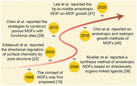 | ||
| Scheme 1 Concise history of anisotropic MOF development: the effective contribution in 1999,17 2002,39 2006,40 2010,43 2016,7,45 2020.18 | ||
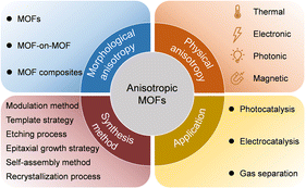 | ||
| Scheme 2 Summary of the morphological anisotropy, physical anisotropy, synthetic methods, and potential applications of anisotropic MOFs. | ||
2. Morphological anisotropy
Manipulating the shape of a particular type of MOF MNP to afford varying degrees of anisotropy is feasible.20 The distinctive geometric characteristics of MOFs arise from interactions between various crystal facets that exhibit distinct growth rates. These varying growth rates are influenced by the attachment energy associated with specific growth units on the crystal facets, which is comparable to the roles that atoms play in creating metal nanocrystals (Scheme 3). Consequently, growth inhibitors impede crystal growth in a specific direction, thereby effectively modulating the growth rates of distinct crystal faces leading to control of MOF morphology.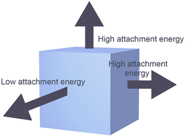 | ||
| Scheme 3 The relative growth rates of MOF crystal facets can impact the geometric shape of the material. | ||
2.1 MOF with various morphologies
MOFs of various size, including nanofibers, nanorods, nanosheets, and nanocubes, have been prepared by controlling anisotropic MOF growth through thermodynamics and dynamics. For example, various forms of zinc imidazole framework-8 (ZIF-8), 2-methylimidazole cobalt salt (ZIF-67), and other materials have been synthesized under various reaction conditions (Fig. 1). The morphology of ZIF-8, including its basic polyhedral, rods, sheets, and hierarchical flower-like structures, can be controlled and adjusted through surfactant assistance.56 In addition, the shapes of nitrogen-doped carbon materials formed from multidimensionally controllable MOFs can be precisely controlled by manipulating the solvent composition and the cobalt-to-linker molar ratio. The resulting materials can exhibit a range of tunable shapes including cube-like, octahedral, dodecahedral, flower-like, and sheet-like structures. The coercivity (Hc) and remanent magnetization (Mr) values of Co@NC specimens were successfully lowered by changing the structure, with the anisotropies of the cubic and sheet-like morphologies exhibiting the highest and lowest Hc values, respectively, among the prepared composites.2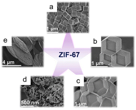 | ||
| Fig. 1 ZIF-67 with various morphologies: (a) cube, (b) dodecahedron, (c) octadecahedron, (d) flower, and (e) sheet. (Panels a–e) Reproduced with permission.2 Copyright 2020, Wiley. | ||
The mechanism for the formation of rhombohedral dodecahedral ZIF-8 crystals was investigated. ZIF-8 crystals are morphologically described as rhombic dodecahedrons, truncated rhombic dodecahedrons, or cubes, which is ascribable to the gradual crystal growth process that begins with the formation of a cube with a complete (100) orientation, which then transforms into a truncated rhombic dodecahedron, and ultimately into a rhombic dodecahedron over time (Fig. 2a).4 The ultimate formation of the rhombic dodecahedral ZIF-8 shape is explained by the Wulff construction principle, which dictates that the final shape is determined by the slowest growth direction ((110) in the case of ZIF-8) as well as the most thermodynamically stable facial orientation. Herein, a polyhedron with 12 rhombic faces is referred to as a “rhombic dodecahedron”, while “truncation” refers to a polyhedron with cutting vertices. The rhombic dodecahedron of ZIF-8 with a “Shelob's onionskin decomposition (SOD) topology” consists of 12 equivalent rhombic (or quadrilateral) faces, all of which are (110) oriented. Alternatively, a truncated rhombic dodecahedron has square truncations at six (100) vertices. The truncated rhomboidal dodecahedral shape consists of 12 (110)-oriented irregular hexagonal sections and six (100)-oriented square sections. The final cube has six faces, all of which are (100) oriented (Fig. 2b–i). Cravillon et al.57 provided comprehensive evidence that the cubic and truncated rhombic dodecahedral shapes of ZIF-8 crystals are ascribable to a form of “unfinished” crystal growth.
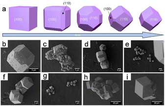 | ||
| Fig. 2 (a) Evolution of ZIF-67 crystal morphology over time. SEM micrographs were taken after 15 min (b and c), 20 min (d and e), 45 min (f and g), and 240 min (h and i). Panels (a–i) Reproduced with permission.4 Copyright 2012, Royal Society of Chemistry. | ||
Based on these results, a morphology-controlled method was recently designed to grow MOFs in a highly anisotropic manner by dynamically adjusting the coordination behaviour at room temperature and environmental pressure using a solid-state metal-ion source.58 In addition, the electronic configurations of the various ions essentially affect the coordination modes of the metal ions. Synergy between the effect of the solvent on the surface coordination arrangement of a MOF and the diverse coordination abilities of Ni2+, Co2+, and N is required to facilitate Co2+/Ni2+-active-site interactions on the surface (Fig. 3).1 Surface-active sites offer ample flexibility for the Ni center, enabling it to attain the optimal coordination state and expose a more significant number of active sites. Creating hollow composite structures by varying the Ni doping concentration is possible owing to the mismatch between the electrical configuration (d8) of Ni2+ and its structure. Additionally, controlling the morphology and aspect ratio facilitated the synthesis of two types of ZIF-78 particle: one with a low aspect ratio and the other with a high aspect ratio. A lower aspect ratio offers more entry points into the ZIF, whereas a higher aspect ratio provides longer highly permeable channels.59
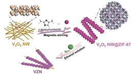 | ||
| Fig. 3 Schematic illustration of the preparation of ZIF-67 on V2O5 NWs (VZN). (Panels) Reproduced with permission.1 Copyright 2023, Wiley. | ||
Significantly, MOF MNPs frequently adopt various asymmetric metal–ligand coordination modes and geometries with distinctive crystal facets on their surfaces. For example, the corners, edges, and faces of a cube within a single MOF MNP exhibit anisotropic properties.60 The morphologies and anisotropic properties of MOF MNPs can be tailored for specific applications by controlling the synthesis conditions and coordination modes. More studies are required to understand the procedures involved in the production of MOFs and develop effective strategies for managing their structures in order to maximize their applications.
2.2 Others
Incorporating various MOFs in hybrid MOF-on-MOF heterostructures has enormous potential in the materials chemistry field.61 The morphologies and structures of MOF-on-MOF structures have been extensively studied as promising materials. In addition, other metal nanoparticles and clusters that grow on MOF substrates, which are known as “depositions of metal nanoparticles” or “clusters on MOFs”, should be noted.62Lee et al.18 pioneered fabricating core–shell hybrid MOFs by selectively growing anisotropic cell lattices on an MIL-88B template surface, resulting in a MIL-88C structure (Fig. 4a and b). Anisotropy develops from the tip to the center during the initial phases of the reaction, which adjusts the cell lattice; however, the cell lattice self-reverts to its original form midway through the reaction. This approach ultimately leads to precisely defined core–shell hybrid MOFs through an anisotropic growth mechanism. Despite having mismatched cell lattices and distinct components, the deposition of Fe-MIL-88C onto the MIL-88B template using an anisotropic growth approach led to the formation of exceptional core–shell structures that are formed through an anisotropic growth mechanism, which ensures distinct and well-defined architectures. In addition, unusual anisotropically created two-shelled hybrid structures were produced (Fig. 4c and d).
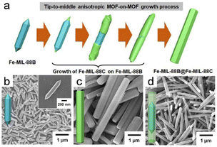 | ||
| Fig. 4 (a) Schematic diagram of the apical to intermediate anisotropic MOF-on-MOF growth process. SEM images of (b) initial hexagonal rods of FeMIL-88B template, (c) pure Fe-MIL-88C hexagonal rods, and (d) Fe-MIL-88B@Fe-MIL-88C core–shell hybrid hexagonal rods. (Panels a–d) Reproduced with permission.18 Copyright 2020, American Chemical Society. | ||
Apart from MOF-on-MOF formation, Wang et al.63 prepared unique 1D Pt@CeO2-BDC microrods from a Pt@CeBDC MOF and hypothesized that the Pt clusters on the CeBDC initiates anisotropic Pt@CeBDC growth, resulting in elongated 1D rods instead of the typical 3D parallelepipeds observed for the CeBDC MOF. Pt-cluster deposition is believed to be the driving force behind this morphological transformation.
3. Physical anisotropy based on MOFs
Physical anisotropy is associated with MOF characteristics that result from the creation of organized lattices, which are fascinating MOF features.52 Pores that face a particular direction can be achieved by carefully designing these materials on the molecular scale. This alignment enables the unique properties of the material, such as enhanced mechanical strength, improved thermal conductivity, enhanced electrical conductivity, and unique photonic properties, to be realized. MOF-oriented thin films possess both out-of-plane and in-plane anisotropic functionalities, which facilitates their use in advanced applications. These thin films can exhibit anisotropic properties in both directions, which qualifies them for a broad range of applications.64 For instance, Zeng et al.65 investigated the mechanical properties of a copper paddlewheel MOF (HKUST-1) through in situ compression tests on micropillars; these researchers focused on two distinct crystallographic orientations, namely the (100) and (111) facets, and constructed stress–strain curves along these directions. This investigation aimed to understand the stress–strain relationship and fracture behaviour of a mechanically anisotropic MOF crystal. The findings revealed anisotropic elastic responses, significant plastic deformation, and variations in yield strength along different crystallographic directions. Physical anisotropy in a MOF is predominantly observed in the form of large single crystals or macroscopic films. However, this area remains relatively unexplored and limited research has been conducted into this novel concept. In this section, we discuss the anisotropic thermal, electronic, photonic, and magnetic properties of MOFs.3.1 Thermal properties
Extreme thermomechanical properties include massive framework expansion and temperature-responsive breathing. Islamov et al.66 discovered that MOFs with high densities, small pores, and metal nodes with four connections tend to exhibit high thermal conductivities. Additionally, researchers identified 36 MOFs that exhibit remarkably low thermal conductivities, which is primarily attributable to their large pores.Metal–organic frameworks functionalized with alkoxyl groups (fu-MOFs), which are represented by the [Zn2(fu-L)2dabco]n general formula, undergo significant uniaxial thermal expansion (Fig. 5a and b; fu-L = alkoxy functionalized 1,4-benzene dicarboxylate, dabco = 1,4-diazabicyclo[2.2.2]octane). Despite being connected to the framework skeleton, the alkoxy side chains of fu-L are significantly conformationally flexible. The thermal motions of these side chains result in a large anisotropic framework expansion that eventually leads to reversible phase transitions in the solid state, accompanied by tructural expansion (Fig. 5c). In particular, the np form underwent extremely anisotropic thermal expansion at specific temperatures (Fig. 5d and e). The thermoresponsive characteristics of these hybrid solid–liquid materials are precisely manipulated by carefully selecting and combining fu-Ls, considering their functional groups and chain lengths. This combinatorial method enables MOFs with exceptional thermomechanical properties to be the deliberately designed, thereby bridging the gap between crystalline solids and liquid states.13
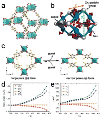 | ||
| Fig. 5 (a) A schematic of the structure of the [Zn2(fu-L1)2dabco]n. (b) Structural illustration showing the x, y, and z vectors in a lattice. (c) Representation of the upon guest molecule removal/re-adsorption. (d) Relative expansion in the range from 303 to 463 K. (e) The temperature-dependent thermal expansion coefficients (α) for the x, y, z dimensions, as well as the volume (V). (Panels a–e) Reproduced with permission.13 Copyright 2013, Wiley. | ||
A 3D flexible MOF with 1D hydrophobic and hydrophilic pores underwent anisotropic thermal expansion between 133 and 383 K, characterized by a significant thermal-expansion coefficient, with the coefficient of thermal expansion along the a-axis (αa) precisely measured to be −21 × 10−6 K−1, while the coefficient along the c-axis (αc) was determined to be 79 × 10−6 K−1. Kondo et al.67 studied the same behavior for 3D flexible MOFs containing one-dimensional hydrophilic and hydrophobic pores. The pores within the MOF deformed as the temperature was varied; particles widened and lengthened during colling, whereas the opposite behavior was observed during heating. These structural transformations are ascribable to the distinctive framework topology, which resembles a lattice fence. The incorporation of silica, as an accommodating material, not only modifies the properties of the MOF but also influences its thermal response. The introduction of a silica source and subsequent hydrolysis resulted in a MOF with notably different unit-cell dimensions. The resulting material selectively blocked hydrophobic pores with silica fillers, transforming the MOF into a hydrophilic microporous material. Additionally, the inclusion of silica led to a significant reduction in pore diameter and the introduction of anisotropic changes in thermal responsiveness.
Moreover, the cadmium-based MOF exhibited similar behavior, with remarkably high thermal-expansion coefficients over a wide temperature range.68 This distinct thermal characteristic emerges from a particular structural attribute that involves pivoting motions around the metal centers within the lattice-fence topology.
3.2 Electronic property
Electronic properties include electrical conductivity and electron transfer. Conductive MOFs have shown great potential for enhancing various technologies, including electrochemical capture and release, energy conversion and storage, chemical sensing, battery systems, and catalysis.69 Charge transport can also be affected by crystal orientation.The relationship between conductivity and network topology in a MOF was investigated by arranging rod-shaped NU-1000 crystallites into arrays that were either parallel or perpendicular to the surface of the substrate.70 The cubic square quinary (CSQ) topology of NU-1000 and its unique one-dimensional mesopores has theoretically been proposed to give rise to direction-dependent anisotropic electrical conductivity. The electronic-coupling strength between linkers is highly influenced by the coupling direction in a hexagonal crystal system that possesses this topology. Researchers have noted that these crystallites align nearly perpendicular to the substrate surface (with a slight tilt) when MOF films are prepared using an interfacial solvothermal method. In contrast, electrophoretic deposition resulted in crystallites parallel to the surface of the substrate (ZnO-coated FTO). The redox conductivity of MOF NU-1000 was shown to exhibit significant anisotropy, with the degree of anisotropy aligned with computational predictions and influenced by the crystallite orientation. In this section, we note that linkers within the a–b plane of the crystal are more weakly and electronically coupled than those in the c direction (channel-aligned direction). A 100-fold lower electrical conductivity was observed when the a–b plane was positioned perpendicular to the underlying electrode in a parallel array configuration.
Anisotropic MOF particles with different conductivity effects can effectively be used to control the formation of desired structures. These synthesized crystalline Ni3HIB2 and Cu3HIB2 MOFs (HIB, HIB = hexaiminobenzene) exhibited pellet conductivities that surpass 800 S cm−1. Density functional theory calculations revealed anisotropic electrical properties, with the a–b direction demonstrating metallic behavior and the c direction displaying semiconducting characteristics within the Brillouin zone.71 In addition, both MOFs exhibited positive correlations between conductivity and temperature.
Hexagonal Ni-MOF [Ni(NO3)2·6H2O, 1,3,5-benzenetricarboxylic acid, 4,4′-bipyridine] was successfully synthesized using a one-step solvothermal method (Fig. 6a–d). Compared to the adjacent rectangular crystal surfaces, the (001) crystal plane of the MOF exhibited the shortest distance for ion diffusion, indicative of a favorable structure for efficient electron transport and ion diffusion.9 Consequently, the exposed (001) crystal plane reduced the distances travelled by electrons and ions through the (001) crystal plane, which are significantly shorter that those of the surrounding rectangular crystal plane; this shortened path accelerates the transportation rate and ultimately enhances electrochemical performance (Fig. 6e).
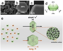 | ||
| Fig. 6 (a–c) SEM images of the Ni-MOF taken at different solvothermal times. (d) Schematic representation of the single crystal structure of hexagonal Ni-MOF. (e) Schematic representation of the charge transfer process on (001) and rectangular crystal planes, respectively. (Panels a–e) Reproduced with permission.9 Copyright 2019, Wiley. | ||
3.3 Photonic property
The interlinked mesh structure that develops on the (001) crystal plane facilitates improved blending with conductive carbon, leading to electrode materials with higher conductivities and expedited electron transfer at the electrode–electrolyte interface.72 The extended molecular structure, which spans long distances within a MOF, and its diverse array are very appealing for creating optical devices owing to its physical characteristics and capacity to orient active guest molecules. Individual MOF layers exhibit robust anisotropic transport properties that facilitate the movement of excitons and other optical excitations within the layered structure.1,4,5,8-Naphthalenediimides (NDIs) belong to a group of organic compounds that exhibit outstanding characteristics in terms of semiconductivity and optics. On the basis of this, Castaldelli et al.73 observed the photoactive response of MOF-CoNDI-py-2. This MOF consists of Co(II) metal centers and N,N′-bis(4-pyridyl)-1,4,5,8-naphthalenediimide (NDI-py) as the π-acceptor. Charge is transferred from the metal center to the NDI when exposed to radiation, which enables hole movement along the Co-TpA axis and electron transport along the NDI-py axis. The synthesized MOF exhibited anisotropic photoconductivity, with the most-intense photoresponse (Jph) observed upon alignment with the charge-transfer band.
Surface-coordinated In-TCPP MOF thin films with (021) orientations were used to fabricate porphyrinic MOF thin films with substantially anisotropic structures. This fabrication process involved the use of In(NO3)3 and 5,10,15,20-tetrakis(4-carboxyphenyl)porphyrin (TCPP). The resulting structure features In-oxo strands aligned parallel to the substrate, immobilizing chromophoric linkers, and 1D arrays of porphyrins. This highly anisotropic arrangement led to localized frontier orbitals within the columnar arrays of porphyrins, resulting in exceptional photoactivity.74 At the same time, switching from isotropic to anisotropic behavior in a completely harmonically invertible manner is possible by coating thin and uniform MOF shells onto anisotropic rod-like superparamagnetic iron-oxide/silica cores (Fig. 7a). These particles luminesce uniformly when exposed to ultraviolet (UV) light, whereas the optical properties of the same sample become directionally dependent when illuminated with visible light (Fig. 7b–e).15
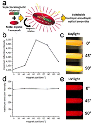 | ||
| Fig. 7 (a) The suggested formulation of an intelligent composite allows for a seamless transition between isotropic and anisotropic characteristics. (b) Variations in the reflection intensities at different angles. (c) Illustration of the angle-dependent magnetic field's impact on light reflection. (d) Emission intensities remain consistent regardless of the direction of the magnetic field. (e) Visualization of the angle-invariant isotropic luminescence properties exhibited by the MOF-functionalized microrods. (Panels a–e) Reproduced with permission.15 Copyright 2017, American Chemical Society. | ||
Unique anisotropic optical properties were observed for a thin MOF film with incorporated Ag nanoparticles (AgNPs) when the MOF crystals were oriented along all three axes over a large area, which demonstrated polarization-dependent plasmonic heating in an oriented AgNP-containing MOF film.64 MOF films oriented and decorated with Ag nanoparticles exhibit distinct and directionally dependent plasmon resonances.75 Spherical AgNPs exhibit polarization-dependent plasmon-resonance absorptions when integrated in an anisotropic MOF lattice, resulting in anisotropic plasmon damping. This anisotropic plasmon resonance results in polarization-dependent plasma-heating behavior. Specifically, the temperature increases the most when the crystal axis of the primary MOF lattice coincides with the polarization direction of the incoming light, which facilitates the generation of significant plasmon resonance. This phenomenon enables temperature control based on the polarization orientation. Polarization-dependent plasmon heating is attributable to the dissimilar plasmonic heating arising from the polarization-dependent plasmon resonance. These AgNPs were implanted in MOF-oriented thin films and acted as localized heat sources.
3.4 Magnetic property
Magnetism has emerged as a captivating area of study in modern physics, recently garnering growing interest. Magnetic MOFs inherit the advantageous characteristics of MOFs, including the ability to efficiently separate and recover magnetic species.76 Composites effectively designed and composed of multiple components can impart significant dielectric and magnetic properties to materials, leading to improved impedance matching.77MOF crystals, namely NH2-MIL-53(Al) and NU-1000, have recently been successfully magnetically aligned. These crystals were magnetized by electrostatically adsorbing iron oxide NPs and dispersed within a curable polymer resin. The MOFs were then magnetically oriented and secured in place via resin curing. The use of a magnetically aligned composite prepared from NU-1000 and Sylgard 184 demonstrated how the crystal orientation affects MOF functioning. The composite displayed a polarization-dependent fluorescence response when excited with linearly polarized 405 nm light, which was influenced by the alignment of the NU-1000 crystals relative to the polarization angle of the excitation beam.78
Among all types of magnetic-based absorbent material, Co- and Ni-based composites exhibit exceptional electromagnetic attenuation capabilities owing to their elevated saturation magnetizations and robust anisotropy fields.77 Significantly, the mechanism responsible for Co/Ni cooperation in the diverse species derived from MOFs has been extensively studied due to the precise atomic structures of these materials. Among commonly employed magnetic metals, cobalt nanoparticles are regarded as ideal magnetic fillers among commonly employed magnetic metals, such as Fe and Ni. This preference stems from the exceptional attributes of Co, including its high saturation magnetization, stability, robust anisotropy, and chemical properties, which significantly amplify the anisotropic fields of Co/C porous nanofiber surfaces, including those of CoNPs produced via high-energy ion-beam evaporation, which is ascribable to the small-size effect. Furthermore, the introduction of nonmagnetic materials led to a lower saturation magnetization (Ms) than that observed for the CoNPs, thereby increasing the energy associated with the anisotropy of the sample beyond that of the CoNPs.79
Other properties also exist. Overall, the physical anisotropies of MOFs contribute to their diverse range of properties, making them promising materials for various applications in the thermal, electrical, optical, and magnetic fields. Investigating new types of physical anisotropic behavior is expected to be a promising future research direction.
4. Synthesis method based on anisotropic MOFs
MOF-based materials with diverse morphologies are feasibly synthesized by manipulating surface parameters, including MOF growth kinetics and their surface energies. This ability to control morphology is a result of the inherent morphological anisotropy of a MOF. Consequently, several synthetic techniques have been developed to leverage this MOF-based anisotropy. Using the directionality of the initial anisotropic MOF single crystal as an advantage, MOF MNPs with controllable morphologies and/or structures were prepared through selective construction, including 1D nanowires and nanorods, 2D thin-film structures, and 3D frame-like hollow structures. Selecting appropriate synthesis methods and reaction conditions is important for these processes. In contrast to morphologically independent anisotropy, morphologically dependent anisotropy enables greater structural flexibility for creating diverse MOF-based materials to a certain extent.20 However, achieving precisely and uniformly synthesized MOF crystals with anisotropic shapes remains significantly challenging. In the next section, we concentrate on exploring various methods for anisotropically growing MOFs that address this challenge, including modulation, templating, etching, epitaxial-growth, self-assembly, and recrystallization.4.1 Modulation method
Modulation synthesis involves controlling the coordination equilibrium with a modulator that competes with the metal or hinders deprotonation of the linker, thereby regulating the synthesis process used to prepare a stable MOF. These modulators drive the formation of MOF crystals in specific directions and are essential for influencing the kinetics of various processes. The anisotropic growth of MOFs with diverse morphologies is enabled by selectively coordinating modulators to particular crystal planes, which impedes MOF growth in some orientations.80 Specific modulators are able to selectively modulate one of the coordination modes while impeding crystal aggregation, thereby promoting anisotropic growth.81The 2D MOF Co2(bim)4 (bim = benzimidazole) nanosheets were synthesized using ammonia (NH4OH) as a modulator (Fig. 8a).19 The involvement of NH4OH in the formation of the [Co(NH3)6]2+ complex through its interaction with Co2+ further supports the role that NH4OH plays as a capping reagent with donor properties. This functionality affects the symmetry of the framework owing to the anisotropic coordination mode facilitated by impairing coordination interactions between Co ions and bim linkers, which led to the formation of 2D Co2(bim)4 nanosheets as a consequence (Fig. 8b–d).
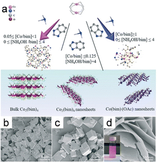 | ||
| Fig. 8 (a) The diagram depicts the process for the synthesis of the Co2(bim)4, the UTCo2(bim)4, as well as the Co(bim)(OAc). SEM images of the Co2(bim)4 prepared using varying amounts of NH4OH (Y value denotes the NH4OH/bim molar ratio): (b) Y = 0; (c) Y = 2; (d) Y = 4. (Panels a–d) Reproduced with permission.19 Copyright 2019, Royal Society of Chemistry. | ||
Furthermore, MOF nanomaterials with diverse morphologies were successfully synthesized using acetic acid and pyridine as modulators (Fig. 9a).14 Monocarboxylic acids and amines were both used to fabricate nanocubes, which entailed simultaneously manipulating the metal–carboxylate and metal–nitrogen coordination modes (Fig. 9b). Surprisingly, nanorods were formed when only acetic acid was used (Fig. 9c), while ultra-thin two-dimensional MOF nanosheets were obtained when only pyridine was used as the tuner (Fig. 9d), which suggests that a monocarboxylic acid, such as acetic acid, that possesses the same carboxylate functionality as the dicarboxylate ligand (ndc; ndc = 1,4-naphthalenedicarboxylate) linker blocks coordination interactions between copper and ndc in the (100) direction. Similarly, coordination between copper and an amine with a nitrogen atom that possesses a lone pair, such as 1,4-diazabicyclo[2.2.2]octane (dabco), hampers growth in the (001) direction in a similar manner to bidentate nitrogen pillar ligands.
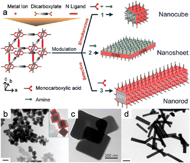 | ||
| Fig. 9 (a) Modulations in coordination for the MOF nanocrystals with controlled morphologies. (b) Morphology evolution of the nanocrystals prepared at acetic acid with pyridine. (c) TEM images of the nanosheets prepared without acetic acid but with pyridine present. (d) TEM images of the nanocrystals fabricated in the presence of amines with acetic acid and n-octylamine triethylamine. (Panels a–d) Reproduced with permission.14 Copyright 2012, American Chemical Society. | ||
Combining a non-MOF material with a MOF is another attractive approach for constructing MOF hybrids. Ultrasmall metal nanosheets (i.e., Pt, Pd, Ag, and Au) can be directionally grown on Ni nanosheets (NSs) by accurately adjusting the metal-ion reduction kinetics.82 Metal ions undergo rapid reduction, resulting in randomly dispersed NPs on the surfaces of the Ni-MOF NSs in the presence of a powerful reducing agent, such as methanol or ethanol. However, the use of the less-reducing diethylene glycol or ethylene glycol slows the reduction kinetics and hinders NP dispersion on the surfaces of the Ni-MOF NSs; metal ions are slowly reduced and preferentially grow on the edges of the MOF NSs, resulting in the edge-directed growth of metal NPs.
Similar schemes have been used to effectively synthesize MOFs with required sizes and morphologies. Uniformly sized single crystals of Cu3BTC2 (BTC3− = benzene-1,3,5-tricarboxylate) were successfully synthesized using the lauric acid preparation method. Lauric acid facilitates appropriate nucleation and growth rates by modulating coordination, leading to uniform crystal size and morphology. Furthermore, the combination of chloroform and methanol (as a double solvent) coordinates the nucleation and growth of NENU-3a, leading to the formation of well-dispersed NENU-3a octahedra. Here, the mixture of chloroform and methanol serves as the epitaxial growth medium, resulting in a noticeable transition in the morphology of the growing particles from cuboctahedral to octahedral, which suggests that NENU-3a exhibits accelerated growth along the (100) crystal direction outside of the Cu3(BTC)2 framework, to align with the inherent octahedral shape of NENU-3a. Consequently, direct pseudo-homoepitaxial growth rapidly constrains the formation of hollow POM@MOF single crystals.83
Modulation synthesis employs modulators to control the morphology, size, and functionality of a MOF. Modulators control the synthesis, influence crystal growth, and enable various morphologies. Anisotropic growth is aided by selectively coordinating crystal planes. Future research is expected to improve MOF performance in separation, catalysis, and other applications. Control is increased in combination with other techniques.
4.2 Template strategy
The template method is widely recognized as a highly effective strategy for synthesizing nanomaterials with adjustable morphologies. Irrespective of whether the chemical reaction occurs in the liquid or gas phase, this technique enables the outcome characteristics to be precisely manipulated by meticulously managing the reaction conditions. The template method is classified into two main types, with both approaches offering distinct advantages for tailoring the morphology of the resulting nanomaterial: the MOF either grows on or is deposited on a template to form a well-defined morphology.Templated MOF-on-MOF growth has rarely been documented. Choi et al.7 examined the anisotropic growth of MOF-NDC (NDC = naphthalene-1,4-dicarboxylic acid) on six rectangular facets of the MIL-68 structure and observed no growth on two hexagonal facets, with abnormal particles formed owing to this unique developmental behavior (Fig. 10a and b). MOF-NDC grew efficiently and anisotropically on the ac plane of the structure because the c-cell parameter is identical to that of the template (Fig. 10c). Nevertheless, uniform growth of MIL-68-Br on the MIL-68 template resulted in the formation of core–shell structures, commonly referred to as MIL-68@MIL-68-Br (Fig. 10d). Inspired by this work, researchers have explored different combinations of MOFs with various crystallographic symmetries to synthesize MOF-on-MOF heterostructures through site-selective epitaxial growth.20
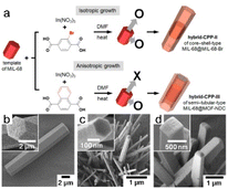 | ||
| Fig. 10 (a) The diagram illustrates the construction of different hybrid type CPPs through isotropic and anisotropic growth. SEM images of (b) hexagonal rods of CPP-I, (c) thin hexagonal rods of CPP-II, and (d) rectangular rods of CPP-III. (Panels a–d) Reproduced with permission.7 Copyright 2016, American Chemical Society. | ||
A unique MOF nanowire that grew along the (220) direction was synthesized.84 The abundance of carboxylic groups in benzoic-acid-functionalized graphene (BFG) created highly dense binding sites that compete for Zn ions, which shifted the kinetic equilibrium; this competition ultimately affected the crystal-growth direction. BFG has been integrated into a MOF as a framework linker that also serves as a template for controlling crystal development and structure, leading to the anisotropic development of 1D MOF nanowires.
Anisotropic heterostructures have been prepared via selective heterogeneous nucleation in surfactant-controlled regions, with heterogeneous nanocrystals subsequently formed. However, the surfactant selectively binds to the surface of the MOF throughout the growth procedure, leading to anisotropy by limiting MOF growth in one or more of the three dimensions to form various ultrathin 2D nanosheets.
A series of ultrathin M-TCPP (M = Zn, Cu, Cd, or Co; TCPP = tetrakis(4-carboxyphenyl)porphyrin) MOF nanosheets was prepared using polyvinylpyrrolidone (PVP) in a surfactant-assisted synthesis protocol.85 The C![[double bond, length as m-dash]](https://www.rsc.org/images/entities/char_e001.gif) O group and Zn2+ ions interact strongly, which enables PVP to bind to the created surfaces following nucleation. This attachment resulted in anisotropic MOF growth, which in turn led to the development of thin Zn-TCPP nanosheets. Yan et al.86 also used PVP as the surfactant, which contributed to the formation of micrometer-sized flower-like NMOF-Ni with a narrow 2–3 μm diameter distribution. The flowers consisted of well-defined petals composed of uniform nanosheets. Cao et al.87 controlled the vertical growth of porphyrin paddlewheel framework-3 (PPF-3) MOF crystals using PVP as an efficient surfactant during the synthesis of 2D PPF-3 nanosheets.
O group and Zn2+ ions interact strongly, which enables PVP to bind to the created surfaces following nucleation. This attachment resulted in anisotropic MOF growth, which in turn led to the development of thin Zn-TCPP nanosheets. Yan et al.86 also used PVP as the surfactant, which contributed to the formation of micrometer-sized flower-like NMOF-Ni with a narrow 2–3 μm diameter distribution. The flowers consisted of well-defined petals composed of uniform nanosheets. Cao et al.87 controlled the vertical growth of porphyrin paddlewheel framework-3 (PPF-3) MOF crystals using PVP as an efficient surfactant during the synthesis of 2D PPF-3 nanosheets.
In summary, the template method is a highly effective strategy for preparing materials with controllable morphologies. Soft and hard template methods have recently been widely used in the design and synthesis of MOFs with morphology-dependent anisotropies. MOFs can be grown or deposited on specific surfaces using templates, resulting in well-defined and tailored morphologies. Selective heterogeneous nucleation within surfactant-controlled regions enables the preparation of anisotropic heterostructure, thereby leading to the formation of heterogeneous nanocrystals. Future research is expected to further explore and optimize template methods with the aim of enhancing the syntheses of nanomaterials with tailored properties and functionalities.
4.3 Etching process
3D Micro-nano composites that feature hollow or interconnected porous structures have been extensively investigated as MOF materials. The well-dispersed pore channels within such MOFs enable effective mass and energy diffusion, rendering them highly suitable for use in diverse applications, including gas separation, sensing, and energy storage. Etching is one of the main methods used to synthesize MOFs with hollow structures, with two types of etching method used: direct and selective. The latter mainly requires specific surfactants that promote etching by selectively changing surface properties.A truncated rhombohedral–dodecahedral ZIF-8 crystal was transformed into a cube with six (110) faces by anisotropic wet-chemical etching using acidizing/alkalizing dimethylphenol orange (XO) as the etching agent.88 The (100) and (211) directions etched faster than the (110) direction owing to the Zn/Co-2-MIM connections on these facets. In addition, each (100) facet, which has a somewhat larger exposed 2D area compared to the 1D (211) edges, facilitates faster etching in the (100) direction; consequently, the etching process resulted in the formation of cubes with (100) faces.
In addition, rhombic dodecahedral ZIF-8/ZIF-67 crystals were preferentially etched from the (211) edges by anisotropic etching with an acid-etchant solvent (XO/HCl, pH 2.5); the etching process was observed to accelerate as these exposed areas increase in size during etching, resulting in the generation of pores at these vertices that serve as openings through which the content is emptied. Avci et al.88 attributed this phenomenon to the crystallographic polarity of the noncentrosymmetric (NCS) ZIF-8/ZIF-67, which results in opposing planes exhibiting different chemical behavior, for the successful formation of hollow microboxes. These observations confirm that the etching process is selective toward the surface and is anisotropic, displaying a preference for crystallographic directions with higher concentrations of metal–ligand bonds and crystal surfaces that are more dimensionally complex.
Etching strategy is also an effective scheme to protect the crystal face in a certain direction and etch the material in the etcher to obtain the desired structure and morphology. Tannic acid can be used as a directed protecting agent that enables the selective etching of NH2-MIL-125(Ti) through hydrolysis from the inside out, resulting in the formation of a TiO2@NH2-MIL-125(Ti) framework.89 This composite material features four active (100) facets on its exterior surface. The (100) surface is more likely to adsorb negative protective molecules because the NH2-MIL-125(Ti) (100) surface possesses a greater number of unsaturated Ti bonds than the (001) surface, which is why tannic acid is adsorbed on the four (100) surfaces, resulting in anisotropic NH2-MIL-125(Ti) etching.
Morphological changes in bulk UiO-66 crystals during anisotropic etching have recently been researched, which provided a schematic of the mechanism responsible for the etching-induced formation of UiO-66 nanosheets (Fig. 11a).5 An etching agent, such as WO42−, is more likely to nucleophilically attack the edges and vertices of bulk UiO-66 crystals during the initial phase. However, facets aligned with the (111) plane remain unaffected by the etching process (Fig. 11b). The interior underwent substantial dissolution during a 2 h etching period, resulting in the creation of a hollow structure. The crystals became thinner in all directions as the etching time was extended to 3 h, with hollow UiO-66 crystals with fully dissolved vertices and separated edges formed (Fig. 11c). Uniform triangular UiO-66 nanoparticles were obtained by completely etching the edges (Fig. 11d). It is worth emphasizing that selective etching occurs at the vertices and edges due to the elevated surface Gibbs free energies in those regions, which suggests that the (110) and (100) facets are more accessible to WO42− ions, leading to preferred etching along the (100) and (110) lattice axes.
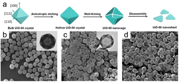 | ||
| Fig. 11 (a) Illustration depicting the formation mechanism of UiO-66 nanosheets. Anisotropic etching of UiO-66 produced by SEM and TEM images for (b) 1 h, (c) 2 h, and (d) 3 h. (Panels a–d) Reproduced with permission.5 Copyright 2023, Wiley. | ||
Etching, which is a prominent method for synthesizing MOFs with hollow structures, can be classified into two main types: direct and selective. Further research is expected to focus on optimizing MOF etching methods to achieve enhanced control over the morphologies and properties of hollow structures. Exploring novel surfactants and how they interact with MOFs may provide new insight into selective etching processes.
4.4 Epitaxial growth strategy
Epitaxy, also known as oriented overgrowth, is a phenomenon in which the crystallographic alignment of the substrate material influences the crystallographic alignment of the deposited film. Epitaxial growth refers to the growth of a single-crystal layer on a single-crystal substrate while adhering to specified guidelines and aligning in the same direction as the substrate crystal. This process can be visualized as an outward extension of the original crystal for a particular period of time.A strategy that eliminates etching was employed to fabricate highly open Co/N-doped carbon nanoframes with precise structural control, and involved several steps: synthesis of 72-facet ZIF-8 seeds, selective epitaxial growth of ZIF-67 on the 36 (110) facets of these ZIF-8 seeds to create an anisotropic ZIF-67-on-ZIF-8 precursor, and the controlled pyrolysis of the anisotropic precursor to achieve a solid-to-frame structural transformation.90 Anisotropic heterostructures were successfully synthesized using this approach. Anisotropic epitaxial growth can also yield a collection of core–shell or striped hetero-Ln-MOF-layered single crystals, with differences possibly attributable to the original seed crystals.91 A bar-shaped seed crystal exhibiting the LIFM-18 phase in the P21/c space group may result from the growth rate along one direction exceeding those in the other two directions, leading to a preference for anisotropic epitaxial growth. Consequently, striped hierarchical crystals with dominant orientations are formed during the early stages of growth. On the other hand, the growth rate along the (001) direction is expected to be comparatively slower for a seed crystal exhibiting the LIFM-19 phase in the I4− space group, resulting in the formation of core–shell crystals. However, this difference gradually increased over an extended period of anisotropic epitaxial growth, resulting in an overall core–shell morphology. These observations reveal that anisotropy depends on the growth rate. However, the degree of growth on each crystal facet gradually became similar as the reaction proceeded, resulting in the disappearance of anisotropy.
MOF heterostructures and core–shell MOF composites were synthesized continuously and ultra-rapidly using this strategy, with kinetic reaction rates faster than those of traditional processes.92 The formation of anisotropic Co3BTC2@Ni3BTC2 crystals is attributable to the monoclinic elongated cell characteristics of the core Co3BTC2 single crystal. Hence, the two-dimensional layers of the core crystal are stacked infinitely along the c-axis, with the crystallographic c-axis aligned parallel to the longest edge. Consequently, transparent Ni3BTC2 shells grew primarily at its ends, which rationalizes the observed epitaxial growth.
To construct several MOF-on-MOF heterostructures, Wu et al.3 used a distinctive anisotropic epitaxial growth approach to construct binary DUT-52@MIL-88B (DM) and DUT-52@MIL-88C (DMC) assemblies. This strategy was subsequently extended to create a DUT-52@MIL-88B@MIL-88C (DMM) ternary assembly (Fig. 12a). Generally, growth occurs on all host-MOF surfaces and in all directions when the lattice of a guest MOF is favorably matched with that of the host MOF, leading to isotropic growth. Anisotropy is observed when a secondary MOF exhibits mismatched lattice development, which usually advances only along a particular surface or direction of the host MOF. The abovementioned reaction demonstrated isotropic growth, resulting in the formation of hexagonal prismatic assembled DMM clusters. Anisotropic epitaxial growth was used to promote growth. In particular, MIL-88C began to epitaxially grow from the top of MIL-88B in DM, with MIL-88C coverage gradually shifting towards the end as the reaction proceeded to eventually completely encapsulate MIL-88B (Fig. 12b and e). This process accounts for the distinctive tip-to-end anisotropic MOF-on-MOF growth (Fig. 12f).
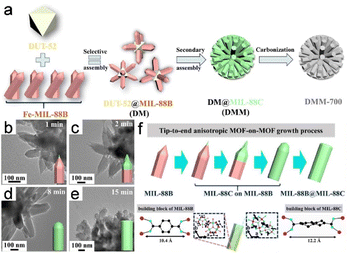 | ||
| Fig. 12 (a) Schematic diagram of synthesis strategies. (b–e) TEM images of DMM. (f) Anisotropic growth of MOF-on-MOF is shown schematically from the tip to the end. (Panels a–f) Reproduced with permission.3 Copyright 2022, Wiley. | ||
Epitaxial growth can be conceptualized as the outward extension of the original crystal over a specific period and can be extensively applied to the synthesis of MOF heterostructures and core–shell composites. In particular, anisotropic epitaxial growth facilitates the formation of anisotropic heterostructures and core–shell composites, where the initial seed crystals determine the final morphology.
4.5 Self-assembly method
The coordination-driven self-assembly of metal ions is among the most common methods for producing MOFs; consequently, it can potentially be used to synthesize MOFs without deliberate human interference. Self-assembly involves the spontaneous formation of a structured arrangement of individual components through valence bond interactions, driven by specific local interactions among the components. The self-assembly approach facilitates the design of biocatalytic cascades with precise control over spatial geometry.An alternative approach involving solvent-assisted self-assembly has been used to create a core–shell bionanocatalyst based on a MOF. In this method, the core of the bionanocatalyst consists of core–shell–shell upconversion nanoparticles (UCNPs), whereas the shells are constructed using iron porphyrin MOFs (Fig. 13a). MOF precursors prefer to nucleate on the carboxylic UCNP surface during this reaction rather than self-nucleating; as a result, unique core–shell UMOFs are formed, as characterized by the discernible lower-contrast MOF domains surrounding the UCNPs (Fig. 13b and d). This finding reveals that the MOFs grew anisotropically on the carboxylic-acid-stabilized UCNP surface.6
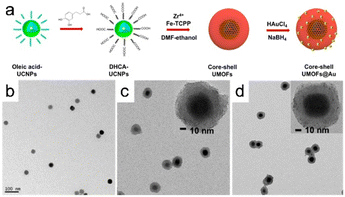 | ||
| Fig. 13 (a) Illustration depicting the formation of core–shell UMOFs@Au NPs. TEM images of (b) carboxylic acid stabilized UCNPs in aqueous solution, UMOF NPs (c), and UMOF@Au NPs (d). (Panels a–d) Reproduced with permission.6 Copyright 2020, American Chemical Society. | ||
In conclusion, the self-assembly of organic ligands and metal ions is a widely employed method for synthesizing MOFs. This approach has the potential to generate MOFs without explicit human intervention, thereby enabling spontaneous formation driven by specific local interactions between the components. This method enables the geometric morphology of a biocascade to be designed and controlled. These findings highlight the potential of self-assembly methods for the synthesis and design of MOFs with desired properties and structures, thereby offering possibilities for various catalysis and biocatalysis applications.
4.6 Recrystallization process
1D MOF crystals have been fabricated by recrystallization, with the morphologies and crystallinities of the resulting crystals significantly influenced by kinetically controlling the crystallization process, that is, by controlling the rates at which crystals form. At the same time, a slow reaction rate promotes the development of anisotropic nanostructures and facilitates the formation of single crystals, which dramatically affects MOF synthesis. However, unlike other synthesis methods, those based on recrystallization have rarely been reported.Recently, Zou et al.8 used a unique technique involving a well-founded recrystallization strategy devoid of surfactants and templates to successfully synthesize 1D superlong single-crystal nanotubes of Co-MOF-74-NTs MOFs. This approach used the recrystallization of amorphous Co-MOF-74-NPs as an influential precursor for the formation of 1D nanostructures with multiple channels (Fig. 14a). A 1D tubular nanostructure consisting of parallel multichannels formed as the Co-MOF-74 nanocrystal grew, owing to the specific anisotropy of the nanotube (Fig. 14b and d). Compared to Co-MOF-74-MR, which is directly formed from the raw materials, recrystallization delivered Co-MOF-74-NTs with a uniform morphology and a high aspect ratio.
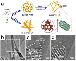 | ||
| Fig. 14 (a) The procedure for synthesizing Co-MOF-74-NT and Co-MOF-74-MR is outlined as follows. (b) TEM images of the Co-MOF-74-NT. (c and d) HRTEM images depicting the lattice fringes of Co-MOF-74-NTs are presented for two distinct nanotubes. (Panels a–d) Reproduced with permission.8 Copyright 2018, American Chemical Society. | ||
1D MOFs have been produced through amorphous-MOF-mediated recrystallization without the use of any surfactant or template. Because this strategy for the synthesis of MOFs is still immature, the formation mechanism and methods for controlling MOFs need to be urgently studied.
4.7 Others
In addition to the methods presented above, several other methods and strategies for synthesizing MOFs and MOF composites have been reported. Some of the unique and creative methods for synthesizing MOF-based materials are difficult to classify to some extent.Researchers successfully synthesized 2D Cu-BDC nanosheets from Cu2O nanocubes as a confined metal-ion source and 1,4-benzenedicarboxylic acid (H2BDC) as the organic linker. The formed crystals are monoclinic in structure, which enables inherent structural anisotropy conducive to 2D MOF growth. Zhan et al.93 successfully synthesized ultrathin Cu-BDC nanosheets under mild conditions owing to the anisotropy of Cu-BDC.
5. Application
Advances in the design, synthesis, and customization of MOFs have significantly broadened their applications in a variety of research domains. The rapid development of MOF-related materials has been facilitated by exploiting the advantages of anisotropic structures to construct MOFs with various structural and functional characteristics. Engineered MOFs show promise in a variety of fields. Anisotropy, a characteristic of a MOF-based material, can be the specific focus of a practical application. In this section, photocatalysis, electrocatalysis, and gas-separation applications are discussed (Table 1).| MOF-based materials | Anisotropic properties | Synthesis methods | Potential applications | Ref. |
|---|---|---|---|---|
| TiO2@MOF FS | Morphological anisotropy | In situ hydrolytic etching method | Photocatalysis | 89 |
| NH2-MIL-125@ZnS | Morphological anisotropy | — | Photocatalysis | 11 |
| NH2-MIL-125 | Morphological anisotropy | Facet/shape-engineering method | Photocatalysis | 95 |
| Cu3BTC2 MOF | Morphological anisotropy | — | Electrocatalysis | 10 |
| Ni-Co BTC | Morphological anisotropy | Chemical etching method | Electrocatalysis | 98 |
| UiO-66 | Morphological anisotropy | Confined counter-diffusion-assisted epitaxial growth | Gas separation | 5 |
| NH2-UiO-66 | Morphological anisotropy | — | Gas separation | 5 |
| ZIF-8 | Morphological anisotropy | Chemical method | Gas separation | 101 |
| [Cu2(bza)4(pyz)]n | Morphological anisotropy | — | Gas separation | 12 |
5.1 Photocatalysis
The use of solar energy to generate chemical energy via photocatalytic processes is a promising solution for addressing current energy-crisis and environmental-pollution challenges. Photocatalysis is a form of catalysis that alters the rate of a photoreaction, which is a chemical reaction that involves the absorption of light by one or more reactants. MOFs that exhibit semiconductor characteristics are potentially good photocatalysts owing to their distinctive ligand-to-metal charge-transfer pathways and exceptional physicochemical properties. MOFs can be extensively employed as photocatalysts for industrial production, particularly in hydrogen-generation and oxygen-reduction applications.Appropriately exposing the active surface of a photocatalytic material improves its photocatalytic activity. The TiO2@NH2-MIL-125(Ti) framework structure (TiO2@MOF FS), which was synthesized anisotropically through in situ hydrolytic etching with directional chemical protection, exhibited remarkably efficient photocatalytic hydrogen generation, thereby eliminating the requirement for precious metals.89 The optical properties of TiO2@MOFs with different morphologies were compared, which revealed that the improved optical-separation, migration, and absorption efficiencies of photogenerated carriers contribute to the improved photocatalytic activity of the photocatalyst. Furthermore, the percentage of exposed active features also significantly influences the observed increase in activity.
A very effective method, which involves the use of photocatalytic hydrogen evolution through water reduction, can be used to meet the rising global demand for energy and mitigate environmental issues associated with nonrenewable fossil fuels. The CdS@MOF-808 MOF-based composite was synthesized by confining photosensitive CdS NPs to the nanospaces of Zr4+-based MOF-808 and positioning them close to catalytic Zr4+ clusters to enhance photocatalytic performance by exploiting the anisotropy of the MOF-based material.94 CdS4@MOF-808 demonstrated effective production of hydrogen under visible light, with a yield significantly higher (approximately 60-times) than that of the composite material in which CdS nanoparticles are supported on the MOF surface. In-depth investigations revealed that the distinct photocatalytic activities of these two similar MOF composites are ascribable to the inhibition of electron–hole recombination. The confinement effect results in a shorter distance for photosensitizer-to-catalytic-core electron transfer, leading to improved photogenerated charge separation. The shorter electron-transport channels consequently increase the yields of photocatalytic reactions, such as hydrogen evolution and carbon dioxide reduction. This study presented a new way of modifying the structure of a photocatalytic system, and the corresponding innovative strategy provides opportunities for significant advancements in photocatalytic activity.
In addition, Liu et al.11 synthesized NH2-MIL-125@ZnS heterostructures with tunable heterojunction coverages as photocatalysts (Fig. 15a and b). The degree of heterojunction coverage is a crucial factor that not only governs the generation and separation of electron–hole pairs, but also the availability of photogenerated electrons and the absorption of light. At the same time, interactions between heterojunction materials determine the ultimate photocatalytic performance. The heterostructure exhibited superior photocatalytic activity for the reduction of O2 following optimization, with activity surpassing those of samples with other heterojunction coverages, highlighting the enhanced performance of the optimized NH2-MIL-125@ZnS heterostructure (Fig. 15c and d).
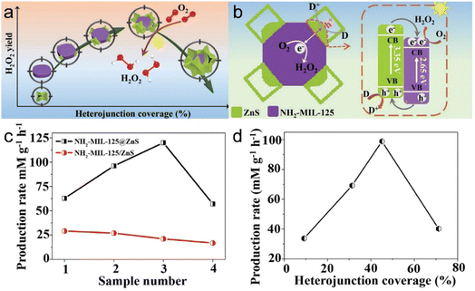 | ||
| Fig. 15 (a) Diagram of (a) the relationship between H2O2 yield and heterojunction coverage and (b) the band structure of NH2-MIL-125/ZnS heterojunction for photocatalytic O2 reduction into H2O2. (c) H2O2 production rate of NH2-MIL-125@ZnS and NH2-MIL-125/ZnS. (d) Normalized H2O2 production rate. (Panels a–d) Reproduced with permission.11 Copyright 2022, Wiley. | ||
A variety of NH2-MIL-125 materials with various morphologies were created using facet/shape-engineering methods, and the photocatalytic performance of these materials toward CO2 reduction was investigated. CO2-photoreduction activity was enhanced with increasing (111)-facet percentage, with the CO2-conversion rate and CO and CH4 yields also systematically enhanced. The (111) crystallographic plane exhibited notable photocatalytic activity. The reported yields are much higher than those obtained for the (001) facet. The (111) crystallographic plane exhibited the highest quantum yield for CO and CH4 production. The enhanced activity of NM111 is attributable to more exposed Ti–O clusters on the (111) surface that serve as active sites, in contrast to the (001) surface.95
The MOF-based material is more tunable than other types of materials to some extent. The catalytic performance of MOF materials can be controlled by adjusting the selective and the ratio of metal ions and organic ligands, altering the catalytic active sites. Different photocatalytic functions are realized by changing the substituent groups.
Research has underscored the importance of optimizing MOF structure and composition for enhancing photocatalytic activity. Subsequent investigations are expected to prioritize advancing MOF photocatalytic performance by constructing heterostructures,96 the precise control of facet/shape engineering,11 and the exploration of additional applications, such as nitrogen fixation.97 However, the heterojunction coverage plays a crucial role in the heterostructures for Photocatalysis, it is overlooked in reported MOFs-based heterostructures.11 Moreover, the detailed effect of temperature-induced composition and amount of the sites on improving the photocatalytic performance was still in progress.96 Also, the low-cost, facile, and large-scale synthesis of MOFs with high catalytic activities is an everlasting target for large-scale industry applications.
5.2 Electrocatalysis
Electrocatalysis is a highly effective method for converting electrical energy into chemical energy, and encompasses processes such as the ORR, CO2RR, and electro-organic syntheses. Among materials used in electrocatalysis, MOFs are particularly favorable because of their notable characteristics, which include extensive surface areas, exceptional porosities, and readily adjustable electronic structures.Liu et al.10 reported that the number of (100) crystallographic planes significantly impact the electrocatalytic glucose activity of Cu3BTC2 MOF nanocrystals. This study presented initial evidence for how the nonenzymatic electrocatalytic activity of Cu3BTC2 nanocrystals towards glucose is influenced by specific nanocrystal planes. Nanocrystals can be synthesized in various shapes, such as nanocubes, truncated cubes, cuboctahedrons, and octahedrons. This work highlighted the roles played by nanocrystal shape and planar orientation in determining electrocatalytic glucose-oxidation performance (Fig. 16a–h). The results reveal that the electrode modified with Cu3BTC2 nanocubes exhibited the most-favorable non-enzymatic electrocatalytic activity toward glucose. Interestingly, non-enzymatic electrocatalytic activity was observed to shift from being highly sensitive to more general as the number of (100) crystal planes decreased during the cube-to-octahedron transition (Fig. 16i and j).
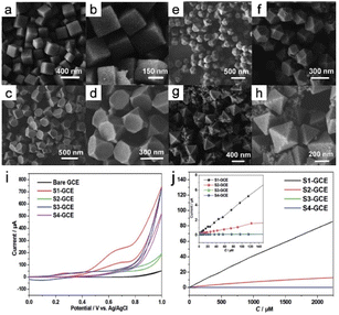 | ||
| Fig. 16 FE-SEM images of the samples were prepared: (a and b) S1, (c and d) S2, (e and f) S3, and (g and h) S4. (i) Cyclic voltammograms of the bare GCE, S1-GCE, S2-GCE, S3-GCE, and S4-GCE. (j) The electrocatalytic current of glucose varies with concentration from 0.125 to 2250 m. (Panels a–j) Reproduced with permission.10 Copyright 2014, Royal Society of Chemistry. | ||
Han et al.98 developed a new approach for fabricating unique Ni–Co Prussian-blue-analog (PBA) nanocages in which pyramidal walls were formed through simple chemical etching with ammonia at room temperature. The cage-like complex structure of the solid Ni-Co BTC nanocube is attributable to the uneven surface reactivity of the material, as evidenced through a series of experiments that demonstrated enhanced OER activity and good durability in alkaline media. Coincidentally, in 2017, a self-templating approach for the synthesis of cubic nanocages composed of Ni–Fe mixed diselenides was reportedly designed for efficient electrocatalytic OER.99 These materials were derived from precursor Prussian-blue-analog nanocubes through selective ammonia etching, which formed the corresponding nanocages. The prepared Ni–Fe mixed diselenide nanocages were exceptionally stable and exhibited superior OER performance in alkaline environments.
Though there are many preponderances of electrocatalysis MOFs, comparing MOF-based material with other traditional materials like noble metals in electrocatalysis, low conductivity, and stability are the disadvantages.
MOFs are regarded as excellent materials for electrochemical applications owing to their substantial surface areas, notable porosities, and adaptable electronic structures. Targeted electrocatalytic efficiencies can be achieved by meticulously optimizing MOF structures (Table 2). Further research is required to overcome obstacles and fully realize their potential for use in energy-conversion and -storage technologies.100 For example, the low stability and low conductivity are the main limits of MOFs, which hamper their electrocatalytic activities. Highly stable MOFs with improved conductivity are crucial for high catalytic activity and long-term durability. Besides, the electrocatalytic performances and the stability of MOFs at large current density needs more research. Developing efficient MOF electrocatalysts working at environmentally benign conditions and neutral-pH electrolyte or even solid electrolytes is still challenging.101
| Materials | Electrolyte | η 10 [mV] | Tafel slope [mV dec−1] | Ref. |
|---|---|---|---|---|
| Ni–Co-mixedoxide nanocages | 1.0 M NaOH | 0.38 V | 50 | 98 |
| Ni–Co-mixedoxide porous cubes | 1.0 M NaOH | — | 59 | 98 |
| Ni–Fe–Se cages | 1.0 M KOH | 240 | 24 | 99 |
| Ni–Fe–Se disks | 1.0 M KOH | 1.47 V | 26 | 99 |
| Ni–Fe–Se cubes | 1.0 M KOH | 30 | 59 | 99 |
| Ni–Fe PBA cages | 1.0 M KOH | 140 | 120 | 99 |
| Ni–Fe PBA disks | 1.0 M KOH | 150 | 127 | 99 |
| Ni–Fe PBA cubes | 1.0 M KOH | 190 | 199 | 99 |
5.3 Gas separation
Gas separation is a crucial and extensively employed industrial procedure used in various applications, including natural-gas or biogas purification, separating atmospheric oxygen and nitrogen, extracting carbon dioxide, and generating hydrogen as a clean fuel. Gas separation involving membrane processes has become increasingly popular in recent years, and film-synthesis methods have gained greater acceptance in research and industry, with the latter showing great interest in microporous materials owing to their efficient gas-separation potentials. These materials have pores with sizes that are well suited for achieving highly selective gas separation, making them valuable for various industrial applications.12In a recent development, confined counter-diffusion-assisted epitaxial growth, a novel technique, was used to effectively fabricate a remarkably well-oriented UiO-66 membrane that exhibited a predominant (111) crystallographic orientation. This achievement marked the first preparation of an oriented 3D MOF membrane that was less than 200 nm thick. A lower membrane thickness and diffusion barrier results in improved CO2 permeance and high CO2/N2 selectivity. These property metrics exceed the limits achieved by current polycrystalline MOF membranes, and set a new standard for membrane performance.5 The distinctive framework topology of UiO-66, along with its preferred (111) orientation, proved to be advantageous for reducing grain-boundary defects. As a result, further enhanced H2/N2 and H2/CH4 selectivity and exceptional operational stability was demonstrated. Furthermore, a highly (111)-oriented NH2-UiO-66 membrane that exhibited outstanding H2/CO2-separation performance was prepared using the same synthetic process. These results highlight tremendous potential for enhancing the separation-capabilities of versatile polycrystalline MOF membranes.
Morphologically tailoring a MOF is highly significant because this technique is applicable to the separation field as well as other domains. The ability to regulate vital properties, such as pore structure, pore size, and surface area, which, in turn, affect the capacity of the MOF to adsorb and separate, is facilitated by tailoring MOF morphology. In addition, the crystal morphology, topology, and lattice defects of a MOF can be controlled using morphological-customization approaches, which affect the mesoscopic structure and overall performance. Uniform ZIF-8 nanocubes approximately 200 nm in size were synthesized by introducing small quantities of cetyltrimethylammonium bromide (CTAB), with octagonal plates subsequently obtained by increasing the CTAB concentration. Even further increases in CTAB content resulted in the formation of uniform ZIF-8 crystals with interpenetrated twin and nanorod morphologies. ZIF-8 shape was found to affect the separation performance of polyethylene oxide-based mixed-matrix membranes toward mixtures of C3H6 and C3H8.101 These findings reveal that the nanorod membrane displays enhanced separation selectivity for C3H6/C3H8 compared to a membrane containing an equivalent amount of ZIF-8; this improvement is attributable to the intense molecular-sieving effect of ZIF-8.
The use of flexible ultra-microporous materials is very promising for the further expansion of gas-purification techniques by developing membrane-based crystal devices. These materials have unidirectional penetration channels that facilitate the transport of various gases even when the kinetic diameter of the evaluated gas is smaller than the neck diameter of the narrow channel. [Cu2(bza)4(pyz)]n (bza = benzoate; pyz = pyrazine) single-crystal membranes exhibited selective and anisotropic permeation properties by exploiting the single-crystalline structure (Fig. 17a and b). In addition, the derived membrane exhibited exceptional separation selectivity for small gas molecules owing to the narrow channels within the crystalline structure. Such gases are of great importance to industry, and processes for their selective separation are considered critical developmental targets (Fig. 17c and d).12
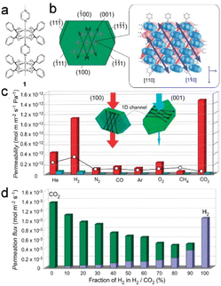 | ||
| Fig. 17 (a and b) The crystal structure of [Cu2(bza)4(pyz)]n (1) with calculated crystal plane numbers and channel direction. (c) The comparison of gas permeabilities through the crystal membrane 1. (d) Comparative analysis of the flow rates of H2 and CO2 passing through the channels of gas mixtures at varying mixing ratios. (Panels a–d) Reproduced with permission.12 Copyright 2010, American Chemical Society. | ||
Because of the high surface areas and tunable pore structures, MOF-based material performance well in gas adsorption. They can be designed to selectively adsorb specific gas molecules based on their pore sizes and chemical functionalities. Other traditional materials, such as activated carbon and silica gel, also exhibit adsorption capabilities but may have lower adsorption capacities and selectivities compared to MOFs.
Diverse micropore architectures can be obtained by controlling the choice and arrangement of organic ligands and metal ions. Anisotropic MOFs exhibit distinct characteristics in terms of selectivity and transfer-rate during gas separation. Their exceptional abilities to separate gas molecules render them exceptionally well-suited for use in gas-purification applications. Furthermore, guaranteeing the long-term stability and sustainability of a MOF is also critical. The permselectivity can be controlled by crystal orientation, porosity, combination with other separation gases, and so on. Therefore, it is challenging to taking the above factors into account to achieve efficient gas separation.12
6. Conclusions and outlook
This review comprehensively examined the synthesis and formation mechanisms of anisotropic MOFs and their potential applications. The diverse anisotropies exhibited by MOFs were thoroughly explored, and synthetic approaches for controlling the morphologies of MOFs with distinct anisotropic structures have been summarized, including modulation methods, template strategies, etching processes, and epitaxial-growth strategies. However, despite these advances, this field remains in its infancy, with many questions yet to be answered, particularly in light of the booming development of other anisotropic materials.(1) The relationships between centers and ligands and the spatial structure need to be further explored. Additionally, effort needs to be directed to compositing MOFs with materials with corresponding capabilities or to adjusting MOF morphology and size by controlling ligand type, chain length, and other dynamic adjustments in order to improve their ion-diffusion and redox capabilities. Optimizing oversized crystal structures enables specific surface areas and active sites to be enhanced leading to optimal anisotropic MOF structures. Such modifications have the potential to increase the use of MOFs in various research applications, including electrochemistry.
(2) Controlling crystal orientation is one of the key elements required to fully exploit MOF crystal anisotropy. Therefore, sufficient attention needs to be paid to crystal structure and its interface with the substrate to ensure that the preferred MOF orientation is achieved, thereby forming a material structure with the required properties. Current MOF research is increasingly focused on precisely synthesizing structured materials. This emphasis arises from a recognition that understanding and manipulating the orientation of a MOF crystal enables its optimal use in various application domains. Notably, controlling the crystal orientation enables the anisotropic characteristics of a MOF to be exploited, including enhanced absorption rates, selective molecular interactions, enantiomeric discrimination, diffusion resistance, conductivity, photoconductivity, and optical properties. Perfect crystallographic orientations are essential for MOFs to be effectively used in a variety of applications, including energy-storage, sensing, catalysis, adsorption, and separation. However, despite its significance, MOF-crystal orientation has received limited attention. While significant resources have been used to create growth methods, studies that focus on the properties and structures of these oriented MOFs have scarcely been reported.40 Exploring the anisotropic properties of MOF crystals for potential applications, particularly in energy-related domains, is promising. The ability to precise manipulate MOF microstructure, including factors such as geometry, size, morphology, and defects, is of paramount importance for enhancing the performance of MOFs for use in advanced applications.52 Controlling the orientation of a MOF crystal remains a highly challenging endeavor, and establishing definitive guidelines for synthesizing oriented MOFs tailored to specific applications is still a distant goal.
(3) From an applications perspective, anisotropic MOFs have been widely used in energy-storage/conversion, catalysis, biomedicine, gas-adsorption/separation, and sensor applications.20 Despite limited research into the relationship between shape and photocatalytic performance, other applications areas have noticeably been hardly investigated. Consequently, much remains to be explored in order to understand the functionalities of MOFs with anisotropic characteristics in various applications. Therefore, leveraging the physical and chemical anisotropies of MOFs is expected to broaden their potential applications in a variety of fields, such as magnetism, mechanics, and optics. Although thermal and electrical anisotropies have been studied and significantly progress has been made, very little anisotropy knowledge is available in other fields. Consequently, more in-depth research is required in these fields.
MOFs will undeniably remain essential and irreplaceable in fields such as chemistry and materials science. Anisotropy is an important characteristic that is essential for structural and functional design. Although research in this field remains at a particular stage, the development and use of more high-performance anisotropic MOFs and exploring them more deeply will lead to more breakthroughs for the synthesis of various complex-structured anisotropic MOFs and their application.
Conflicts of interest
There are no conflicts to declare.Acknowledgements
This work was supported by the National Natural Science Foundation of China (52371240, U1904215), Natural Science Foundation of Jiangsu Province (BK20200044), Changjiang scholars program of the Ministry of Education (Q2018270), Jiangsu Specially-Appointed Professors Program, and the Postgraduate Research & Practice Innovation Program of Jiangsu Province (KYCX21_3199).Notes and references
- H. J. Zhou, G. Y. Zhu, S. Y. Dong, P. Liu, Y. Y. Lu, Z. Zhou, S. Cao, Y. Z. Zhang and H. Pang, Adv. Mater., 2023, 35, 11 Search PubMed.
- M. Q. Huang, L. Wang, K. Pei, W. B. You, X. F. Yu, Z. C. Wu and R. C. Che, Small, 2020, 16, 11 Search PubMed.
- F. Wu, L. Y. Wan, Q. Y. Li, Q. Y. Zhang and B. L. Zhang, Compos. B. Eng., 2022, 236, 14 CrossRef.
- J. Cravillon, C. A. Schröder, H. Bux, A. Rothkirch, J. Caro and M. Wiebcke, Crystengcomm, 2012, 14, 492–498 RSC.
- Y. W. Sun, J. H. Yan, Y. L. Gao, T. T. Ji, S. X. Chen, C. Wang, P. Lu, Y. S. Li and Y. Liu, Angew. Chem., Int. Ed., 2023, 62, e202216697 CrossRef CAS PubMed.
- L. C. He, Q. Q. Ni, J. Mu, W. P. Fan, L. Liu, Z. T. Wang, L. Li, W. Tang, Y. J. Liu, Y. Y. Cheng, L. G. Tang, Z. Yang, Y. Liu, J. H. Zou, W. J. Yang, O. Jacobson, F. Zhang, P. T. Huang and X. Y. Chen, J. Am. Chem. Soc., 2020, 142, 6822–6832 CrossRef CAS PubMed.
- S. Choi, T. Kim, H. Ji, H. J. Lee and M. Oh, J. Am. Chem. Soc., 2016, 138, 14434–14440 CrossRef CAS PubMed.
- L. L. Zou, C. C. Hou, Z. Liu, H. Pang and Q. Xu, J. Am. Chem. Soc., 2018, 140, 15393–15401 CrossRef CAS PubMed.
- Y. Li, Y. X. Xu, Y. Liu and H. Pang, Small, 2019, 15, 8 Search PubMed.
- Y. Y. Liu, Y. J. Zhang, J. Chen and H. Pang, Nanoscale, 2014, 6, 10989–10994 RSC.
- C. Liu, T. Bao, L. Yuan, C. Q. Zhang, J. Wang, J. J. Wan and C. Z. Yu, Adv. Funct. Mater., 2022, 32, 9 Search PubMed.
- S. Takamizawa, Y. Takasaki and R. Miyake, J. Am. Chem. Soc., 2010, 132, 2862 CrossRef CAS PubMed.
- S. Henke, A. Schneemann and R. A. Fischer, Adv. Funct. Mater., 2013, 23, 5990–5996 CrossRef CAS.
- M. H. Pham, G. T. Vuong, F. G. Fontaine and T. O. Do, Cryst. Growth Des., 2012, 12, 3091–3095 CrossRef CAS.
- K. Mandel, T. Granath, T. Wehner, M. Rey, W. Stracke, N. Vogel, G. Sextl and K. Müller-Buschbaum, ACS Nano, 2017, 11, 779–787 CrossRef CAS PubMed.
- B. Li, H. M. Wen, Y. J. Cui, W. Zhou, G. D. Qian and B. L. Chen, Adv. Mater., 2016, 28, 8819–8860 CrossRef CAS PubMed.
- H. Li, M. Eddaoudi, M. O'Keeffe and O. M. Yaghi, Nature, 1999, 402, 276–279 CrossRef CAS.
- G. Lee, S. Lee, S. Oh, D. Kim and M. Oh, J. Am. Chem. Soc., 2020, 142, 3042–3049 CrossRef CAS PubMed.
- P. Nian, H. O. Liu and X. F. Zhang, Crystengcomm, 2019, 21, 3199–3208 RSC.
- T. Bao, Y. Y. Zou, C. Q. Zhang, C. Z. Yu and C. Liu, Angew. Chem., Int. Ed., 2022, 61, 13 Search PubMed.
- J. L. Han, X. D. He, J. Liu, R. J. Ming, M. H. Lin, H. Li, X. C. Zhou and H. X. Deng, Chem, 2022, 8, 1637–1657 CAS.
- A. E. Baumann, D. A. Burns, B. Q. Liu and V. S. Thoi, Commun. Chem., 2019, 2, 14 CrossRef.
- J. Fonseca and S. Choi, Dalton Trans., 2021, 50, 3145–3154 RSC.
- T. Rodenas, I. Luz, G. Prieto, B. Seoane, H. Miro, A. Corma, F. Kapteijn, F. Xamena and J. Gascon, Nat. Mater., 2015, 14, 48–55 CrossRef CAS PubMed.
- J. Lee, O. K. Farha, J. Roberts, K. A. Scheidt, S. T. Nguyen and J. T. Hupp, Chem. Soc. Rev., 2009, 38, 1450–1459 RSC.
- J. W. Liu, L. F. Chen, H. Cui, J. Y. Zhang, L. Zhang and C. Y. Su, Chem. Soc. Rev., 2014, 43, 6011–6061 RSC.
- R. R. Salunkhe, Y. V. Kaneti and Y. Yamauchi, ACS Nano, 2017, 11, 5293–5308 CrossRef CAS PubMed.
- Z. J. Chen, K. O. Kirlikovali, P. Li and O. K. Farha, Acc. Chem. Res., 2022, 55, 579–591 CrossRef CAS PubMed.
- W. Xia, A. Mahmood, R. Q. Zou and Q. Xu, Energy Environ. Sci., 2015, 8, 1837–1866 RSC.
- S. M. Li, S. S. Shan, S. Chen, H. B. Li, Z. Y. Li, Y. X. Liang, J. Y. Fei, L. H. Xie and J. R. Li, J. Environ. Chem. Eng., 2021, 9, 21 Search PubMed.
- H. Musarurwa and N. T. Tavengwa, Mater. Today Commun., 2022, 33, 10 Search PubMed.
- Y. T. Qian, F. F. Zhang and H. Pang, Adv. Funct. Mater., 2021, 31, 34 Search PubMed.
- H. Li, K. C. Wang, Y. J. Sun, C. T. Lollar, J. L. Li and H. C. Zhou, Mater. Today, 2018, 21, 108–121 CrossRef CAS.
- J. R. Li, R. J. Kuppler and H. C. Zhou, Chem. Soc. Rev., 2009, 38, 1477–1504 RSC.
- W. D. Fan, X. R. Zhang, Z. X. Kang, X. P. Liu and D. F. Sun, Coord. Chem. Rev., 2021, 443, 57 CrossRef.
- R. Banerjee, A. Phan, B. Wang, C. Knobler, H. Furukawa, M. O'Keeffe and O. M. Yaghi, Science, 2008, 319, 939–943 CrossRef CAS PubMed.
- A. R. Millward and O. M. Yaghi, J. Am. Chem. Soc., 2005, 127, 17998–17999 CrossRef CAS PubMed.
- N. L. Rosi, J. Eckert, M. Eddaoudi, D. T. Vodak, J. Kim, M. O'Keeffe and O. M. Yaghi, Science, 2003, 300, 1127–1129 CrossRef CAS PubMed.
- M. Eddaoudi, J. Kim, N. Rosi, D. Vodak, J. Wachter, M. O'Keeffe and O. M. Yaghi, Science, 2002, 295, 469–472 CrossRef CAS PubMed.
- I. E. Khalil, J. Fonseca, M. R. Reithofer, T. Eder and J. M. Chin, Coord. Chem. Rev., 2023, 481, 32 CrossRef.
- X. Liu, J. S. Meng, J. X. Zhu, M. Huang, B. Wen, R. T. Guo and L. Q. Mai, Adv. Mater., 2021, 33, 34 Search PubMed.
- H. D. Lawson, S. P. Walton and C. Chan, ACS Appl. Mater. Interfaces, 2021, 13, 7004–7020 CrossRef CAS PubMed.
- U. Mueller, M. Schubert, F. Teich, H. Puetter, K. Schierle-Arndt and J. Pastré, J. Mater. Chem., 2006, 16, 626–636 RSC.
- K. K. Gangu and S. B. Jonnalagadda, Surface Modification of Metal-Organic Frameworks for Biomedical Applications, Woodhead Publ Ltd, Officers Mess Business Centre, Royston Rd, Cambridge, Duxford, Uk, 2020 Search PubMed.
- B. L. Chen, S. C. Xiang and G. D. Qian, Acc. Chem. Res., 2010, 43, 1115–1124 CrossRef CAS PubMed.
- H. Y. Li, S. N. Zhao, S. Q. Zang and J. Li, Chem. Soc. Rev., 2020, 49, 6364–6401 RSC.
- N. Stock and S. Biswas, Chem. Rev., 2012, 112, 933–969 CrossRef CAS PubMed.
- Y. C. Zhang, Z. H. Lin, Q. W. He, Y. F. Deng, F. X. Wei, C. H. Xu, L. H. Fu and B. F. Lin, Appl. Surf. Sci., 2022, 571, 12 Search PubMed.
- M. A. Andrés, C. Sicard, C. Serre, O. Roubeau and I. Gascón, Beilstein J. Nanotechnol., 2019, 10, 654–665 CrossRef PubMed.
- O. Shekhah, H. K. Arslan, K. Chen, M. Schmittel, R. Maul, W. Wenzel and C. Wöll, Chem. Commun., 2011, 47, 11210–11212 RSC.
- K. K. Sun, L. Li, X. L. Yu, L. Liu, Q. T. Meng, F. Wang and R. Zhang, J. Colloid Interface Sci., 2017, 486, 128–135 CrossRef CAS PubMed.
- Z. Rahmati, R. Khajavian and M. Mirzaei, Inorg. Chem. Front., 2021, 8, 3581–3586 RSC.
- S. G. Johnson and J. D. Joannopoulos, Opt. Express, 2001, 8, 173–190 CrossRef CAS PubMed.
- A. Nader, Physica C, 2001, 356, 261–267 CrossRef CAS.
- R. Haldar, M. Jakoby, A. Mazel, Q. Zhang, A. Welle, T. Mohamed, P. Krolla, W. Wenzel, S. Diring, F. Odobel, B. S. Richards, I. A. Howard and C. Wöll, Nat. Commun., 2018, 9, 8 CrossRef PubMed.
- J. Troyano, A. Carné-Sánchez, C. Avci, I. Imaz and D. Maspoch, Chem. Soc. Rev., 2019, 48, 5534–5546 RSC.
- J. Cravillon, C. A. Schröder, R. Nayuk, J. Gummel, K. Huber and M. Wiebcke, Angew. Chem., Int. Ed., 2011, 50, 8067–8071 CrossRef CAS PubMed.
- G. W. Zhan and H. C. Zeng, Adv. Funct. Mater., 2016, 26, 3268–3281 CrossRef CAS.
- M. van Essen, L. van den Akker, R. Thur, M. Houben, I. F. J. Vankelecom, Z. Borneman and K. Nijmeijer, Adv. Mater. Interfaces, 2021, 8, 9 Search PubMed.
- L. Feng, K. Y. Wang, G. S. Day and H. C. Zhou, Chem. Soc. Rev., 2019, 48, 4823–4853 RSC.
- C. Liu, Q. Sun, L. Lin, J. Wang, C. Q. Zhang, C. H. Xia, T. Bao, J. J. Wan, R. Huang, J. Zou and C. Z. Yu, Nat. Commun., 2020, 11, 8 CrossRef PubMed.
- S. Peng, M. Li, X. X. Yang, P. H. Li, H. Liu, W. Xiong and X. Y. Peng, Ceram. Int., 2019, 45, 18128–18134 CrossRef CAS.
- Q. Y. Wang, Y. X. Li, A. Serrano-Lotina, W. Han, R. Portela, R. X. Wang, M. A. Bañares and K. L. Yeung, J. Am. Chem. Soc., 2021, 143, 196–205 CrossRef CAS PubMed.
- K. Okada, R. Mashita, A. Fukatsu and M. Takahashi, Nanoscale Adv., 2023, 5, 1795–1801 RSC.
- Z. X. Zeng, Y. Xiao, J. M. Wheeler and J. C. Tan, Commun. Chem., 2023, 6, 7 CrossRef PubMed.
- M. Islamov, H. Babaei, R. Anderson, K. B. Sezginel, J. R. Long, A. J. H. McGaughey, D. A. Gomez-Gualdron and C. E. Wilmer, npj Comput. Mater., 2023, 9, 12 CrossRef.
- A. Kondo and K. Maeda, J. Solid State Chem., 2015, 221, 126–131 CrossRef CAS.
- L. D. DeVries, P. M. Barron, E. P. Hurley, C. H. Hu and W. Choe, J. Am. Chem. Soc., 2011, 133, 14848–14851 CrossRef CAS PubMed.
- M. Ko, L. Mendecki and K. A. Mirica, Chem. Commun., 2018, 54, 7873–7891 RSC.
- S. Goswami, I. Hod, J. D. Duan, C. W. Kung, M. Rimoldi, C. D. Malliakas, R. H. Palmer, O. K. Farha and J. T. Hupp, J. Am. Chem. Soc., 2019, 141, 17696–17702 CrossRef CAS PubMed.
- J. H. Dou and M. Dinca, Abstr. Pap. Am. Chem. Soc., 2018, 255, 2 Search PubMed.
- J. L. Xu and X. H. Bu, Adv. Opt. Mater., 2021, 9, 2 Search PubMed.
- E. Castaldelli, K. Jayawardena, D. C. Cox, G. J. Clarkson, R. I. Walton, L. Le-Quang, J. Chauvin, S. R. P. Silva and G. J. F. Demets, Nat. Commun., 2017, 8, 8 CrossRef PubMed.
- Y. B. Tian, N. Vankova, P. Weidler, A. Kuc, T. Heine, C. Wöll, Z. G. Gu and J. Zhang, Adv. Sci., 2021, 8, 8 Search PubMed.
- K. Ikigaki, K. Okada, Y. Tokudome, T. Toyao, P. Falcaro, C. J. Doonan and M. Takahashi, Angew. Chem., Int. Ed., 2019, 58, 6886–6890 CrossRef CAS PubMed.
- M. Arjmandi, A. Altaee, A. Arjmandi, M. P. Chenar, M. Peyravi and M. Jahanshahi, Solid State Sci., 2020, 106, 6 CrossRef.
- Y. Liu, X. F. Zhou, Z. R. Jia, H. J. Wu and G. L. Wu, Adv. Funct. Mater., 2022, 32, 10 Search PubMed.
- F. Cheng, E. S. Marshall, A. J. Young, P. J. Robinson, J. S. G. Bouillard, A. M. Adawi, N. A. Vermeulen, O. K. Farha, M. R. Reithofer and J. M. Chin, Chem.–Eur. J., 2017, 23, 15578–15582 CrossRef CAS PubMed.
- Y. X. Zhu, S. F. Wang, Y. S. Zhang, Z. G. Wu, B. Zhong, D. R. Li, F. Y. Wang, J. J. Feng, J. Tang, R. F. Zhuo and P. X. Yan, Sci. Rep., 2021, 11, 14 CrossRef PubMed.
- J. Wang, N. Li, Y. X. Xu and H. Pang, Chem.–Eur. J., 2020, 26, 6402–6422 CrossRef CAS PubMed.
- T. Tsuruoka, S. Furukawa, Y. Takashima, K. Yoshida, S. Isoda and S. Kitagawa, Angew. Chem., Int. Ed., 2009, 48, 4739–4743 CrossRef CAS PubMed.
- M. J. Wang, Y. Xu, C. K. Peng, S. Y. Chen, Y. G. Lin, Z. W. Hu, L. Sun, S. Y. Ding, C. W. Pao, Q. Shao and X. Q. Huang, J. Am. Chem. Soc., 2021, 143, 16512–16518 CrossRef CAS PubMed.
- Z. Zhang, X. J. Ma, X. Han, H. Cui, Y. Lu, S. X. Liu and Y. W. Liu, Sci. China: Chem., 2022, 65, 1921–1928 CrossRef CAS.
- M. Jahan, Q. L. Bao, J. X. Yang and K. P. Loh, J. Am. Chem. Soc., 2010, 132, 14487–14495 CrossRef CAS PubMed.
- M. T. Zhao, Y. X. Wang, Q. L. Ma, Y. Huang, X. Zhang, J. F. Ping, Z. C. Zhang, Q. P. Lu, Y. F. Yu, H. Xu, Y. L. Zhao and H. Zhang, Adv. Mater., 2015, 27, 7372–7378 CrossRef CAS PubMed.
- R. Yan, Y. Zhao, H. Yang, X. J. Kang, C. Wang, L. L. Wen and Z. D. Lu, Adv. Funct. Mater., 2018, 28, 8 Search PubMed.
- F. F. Cao, M. T. Zhao, Y. F. Yu, B. Chen, Y. Huang, J. Yang, X. H. Cao, Q. P. Lu, X. Zhang, Z. C. Zhang, C. L. Tan and H. Zhang, J. Am. Chem. Soc., 2016, 138, 6924–6927 CrossRef CAS PubMed.
- C. Avci, J. Ariñez-Soriano, A. Carné-Sánchez, V. Guillerm, C. Carbonell, I. Imaz and D. Maspoch, Angew. Chem., Int. Ed., 2015, 54, 14417–14421 CrossRef CAS PubMed.
- L. M. Sun, Y. S. Yuan, F. Wang, Y. L. Zhao, W. W. Zhan and X. G. Han, Nano Energy, 2020, 74, 8 CrossRef.
- Y. H. Wu, L. Y. Chen, X. F. Yang, Y. W. Li and K. Shen, Sci. China: Chem., 2022, 65, 2450–2461 CrossRef CAS.
- M. Pan, Y. X. Zhu, K. Wu, L. Chen, Y. J. Hou, S. Y. Yin, H. P. Wang, Y. N. Fan and C. Y. Su, Angew. Chem., Int. Ed., 2017, 56, 14582–14586 CrossRef CAS PubMed.
- M. Faustini, J. Kim, G. Y. Jeong, J. Y. Kim, H. R. Moon, W. S. Ahn and D. P. Kim, J. Am. Chem. Soc., 2013, 135, 14619–14626 CrossRef CAS PubMed.
- G. W. Zhan, L. L. Fan, F. G. Zhao, Z. L. Huang, B. Chen, X. Yang and S. F. Zhou, Adv. Funct. Mater., 2019, 29, 13 Search PubMed.
- A. Ghosh, S. Karmakar, F. A. Rahimi, R. S. Roy, S. Nath, U. K. Gautam and T. K. Maji, ACS Appl. Mater. Interfaces, 2022, 14, 25220–25231 CrossRef CAS PubMed.
- X. M. Cheng, X. Y. Dao, S. Q. Wang, J. Zhao and W. Y. Sun, ACS Catal., 2021, 11, 650–658 CrossRef CAS.
- Q. Zhang, J. H. Zhang, X. H. Wang, L. F. Li, Y. F. Li and W. L. Dai, ACS Catal., 2021, 11, 6276–6289 CrossRef CAS.
- K. An, H. J. Ren, D. Yang, Z. F. Zhao, Y. C. Gao, Y. Chen, J. D. Tan, W. J. Wang and Z. Y. Jiang, Appl. Catal., B, 2021, 292, 14 CrossRef.
- L. Han, X. Y. Yu and X. W. Lou, Adv. Mater., 2016, 28, 4601–4605 CrossRef CAS PubMed.
- J. W. Nai, Y. Lu, L. Yu, X. Wang and X. W. Lou, Adv. Mater., 2017, 29, 8 CrossRef PubMed.
- Y. Z. Chen, C. M. Wang, Z. Y. Wu, Y. J. Xiong, Q. Xu, S. H. Yu and H. L. Jiang, Adv. Mater., 2015, 27, 5010–5016 CrossRef CAS PubMed.
- F. Yang, H. Mu, C. Q. Wang, L. Xiang, K. X. Yao, L. M. Liu, Y. Yang, Y. Han, Y. S. Li and Y. C. Pan, Chem. Mat., 2018, 30, 3467–3473 CrossRef CAS.
| This journal is © The Royal Society of Chemistry 2024 |
