 Open Access Article
Creative Commons Attribution 3.0 Unported Licence
Two-photon laser printing of 3D multicolor emissive polymer microstructures†
Finn
Kröger
ab,
Robert
Eichelmann
 c,
Gabriel
Sauter
d,
Audrey
Pollien
 de,
Petra
Tegeder
 d,
Lutz H.
Gade
 *c and
Eva
Blasco
 *ab
*ab
aInstitute for Molecular Systems Engineering and Advanced Materials, Universität Heidelberg, Im Neuenheimer Feld 225, 69120 Heidelberg, Germany
bOrganisch-Chemisches Institut, Universität Heidelberg, Im Neuenheimer Feld 270, Heidelberg 69120, Germany. E-mail: eva.blasco@uni-heidelberg.de
cAnorganisch-Chemisches Institut, Universität Heidelberg, Im Neuenheimer Feld 270, 69120 Heidelberg, Germany. E-mail: lutz.gade@uni-heidelberg.de
dPhysikalisch-Chemisches Institut, Universität Heidelberg, Im Neuenheimer Feld 253, 69120 Heidelberg, Germany
eUniversité Paris-Saclay, École Normale Supérieure Paris-Saclay, 4 Av. des Sciences, 91190 Gif-sur-Yvette, France
First published on 17th June 2024
Abstract
In this study, we aim for the fabrication of precise multi-color 3D microstructures utilizing organic emitters. We have carefully selected dyes with red, green, and blue (RGB) emission characteristics and incorporated them into printable formulations suitable for two-photon laser printing (2PLP). Specifically, we have chosen an OAPPDO derivative, a boron dipyrromethene difluoride (BODIPY), and a coumarin derivative as red, green, and blue emitters, respectively, each functionalized with acrylate groups. The photopolymerizable groups allow for covalent linking to the polymer network formed in the subsequent step, enabling precise control over the incorporation of the desired emitter. The formulations including these three photopolymerizable dyes have been employed to print emissive 3D microstructures via 2PLP. Furthermore, we have studied and optimized their printability, resolution, and emission properties for each case. In a last step, we have fabricated complex multi-material 3D microstructures, demonstrating the versatility and potential application of our method in displays or anti-counterfeiting systems.
Introduction
Additive manufacturing, also known as 3D printing, is a rapidly advancing technology characterized by its ability to fabricate 3D objects across a broad range of sizes, depending on the specific printing methodology employed.1 Light based technologies relying on photopolymerization processes exhibit numerous benefits including high resolution, speed, and the generation of intricate and detailed objects with smooth surfaces.1,2 A suitable tool for the fabrication of complex 3D structures with a submicron resolution is two-photon laser printing (2PLP), also known as multi-photon laser printing, since also more than two photons can be involved in the initiation process.3 Over the past decade, great efforts have been made to incorporate various functionalities into printable materials for 2PLP related, inter alia, to their responsive properties, their conductivity or biocompatibility, opening new avenues in several fields.4,5Light emissive materials are an important class of materials that have found applications across various fields including but not limited to organic light-emitting diodes (OLEDs),6 sensors,7 security features and imaging.5 The utilization of printing techniques for such light emissive materials presents a versatile and efficient approach in the fabrication of luminescent devices, particularly when integrating multiple emitters.8,9 For example, inkjet printing has been employed for the fabrication of (multi-material) patterns that can be used as active layers in displays by using inks containing quantum dots that emit different colors.10,11 This approach is, however, limited to the realization of planar 2D devices.8,10 Recently, formulations containing quantum dots have been optimized for their use in 2PLP, enabling the fabrication of complex 3D structures. For example, it was shown that CdSSe-based core–shell semiconductor quantum dots in an acrylate-based formulation were suitable for the fabrication of anti-counterfeiting features.12,13 In this approach, information could be stored inside a 3D structure, which subsequently could be “read” by using confocal laser scanning microscopy.13
Organic emitters offer fine tunability of their photophysical properties and solubility, through targeted structural modifications. This is of special significance for their use in light-based 3D printing. On the other hand, there are challenges including poor miscibility of the dyes in formulations commonly used in 3D printing, which often consist of hydrophobic acrylate monomers and crosslinkers. Furthermore, most of the reported work for 2PLP has been limited to the use of a few commercial fluorescent dyes, such as rhodamine derivatives, which suffer from poor photostability.14 Hence, there is an evident necessity to explore alternative, stable, and versatile fluorophores compatible with 2PLP.
In a recent work, we have introduced tetraazaperylene derivates as new fluorophores and investigated their suitability for the preparation of emissive 3D microstructures.15 In particular, octaazaperopyrenedioxides (OAPPDOs) have been found to be good emitters both in solution and in the solid state.16–18 In these studies, several OAPPDO derivatives were added into a formulation consisting of a tri-acrylate crosslinker and photoinitiator and were successfully employed for the 3D printing of complex microstructures using 2PLP. The 3D printed microstructure exhibited fluorescence throughout the entire 3D microstructure demonstrating that the emitter was successfully embedded. Nevertheless, as the emitter was merely physically trapped within the 3D printed networks, the potential for “leakage” of the emitter during the washing process remained inevitable, resulting in a loss of control over the final emitter concentration and consequently, affecting the performance of the functional structures.
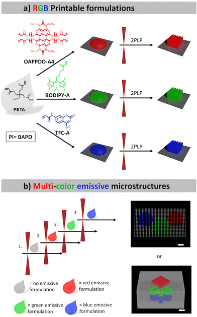
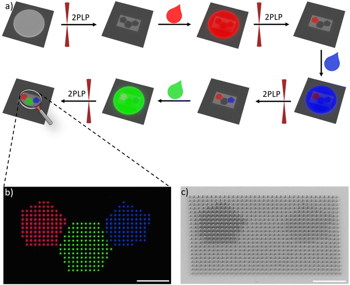
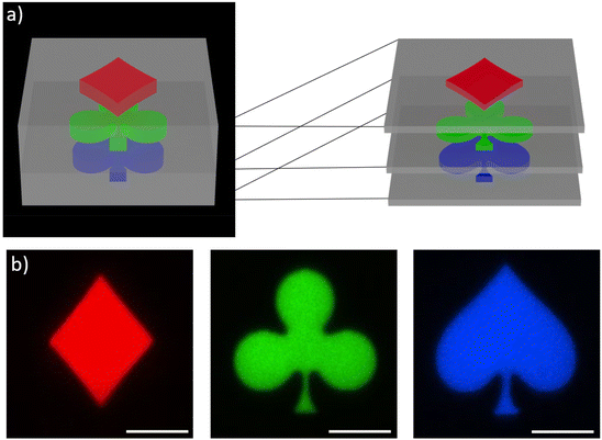
In this study, we aim to manufacture defined multi-color 3D microstructures relying on organic emitters. To this end, we selected several dyes exhibiting red, green, and blue (RGB) emission, which can be employed in a printable formulation suitable for 2PLP. Specifically, an OAPPDO derivative, a modified boron dipyrromethene difluoride (BODIPY) as well as coumarin derivatives were chosen as red, green, and blue emitters, respectively, and functionalized with acrylate groups. Our strategy of using dyes decorated with acrylate groups enabled covalent bonding to the generated polymer network in the subsequent step and therefore the incorporation of the targeted emitter in a more controllable manner. The three photopolymerizable dyes were included in formulations and employed for the printing of emissive 3D microstructures using 2PLP (Fig. 1a). Their printability, resolution as well as the emission properties of the printed microstructures were carefully studied and optimized for the three cases. Finally, multi-material 3D microstructures were prepared (Fig. 1b) to generate multi-color emissive architectures illustrating their versatility and potential for application in displays or anti-counterfeiting systems.
Results and discussion
RGB photopolymerizable emitters
The initial step involved the investigation of the fluorophores emitting across the visible regime (red, green, and blue, RGB) that were compatible with two-photon absorption polymerization using an IR laser. The approach utilized three classes of dyes emitting in RGB regions that could be easily functionalized with photopolymerizable groups such as acrylates and were then integrated in printable formulations. The functionalization allowed for covalent bonding to the formed polymer network, facilitating the controlled integration of the desired emitter.An OAPPDO derivative was strategically selected as the red emitter owing to its outstanding fluorescence characteristics.15,16 Specifically, compound 1 (see details for the synthesis in the Experimental section), featuring chlorine substitution at the bay-position and a n-hexyl functionalized urea fragment in the peri-position, was chosen as the starting material.17,18 The n-hexyl-chains at the urea motives provide sufficient solubility and the chlorides in the bay-position enable further structural functionalization. Thus, the corresponding photocrosslinkable groups can be easily introduced by functionalization first with 6-mercapto-1-hexanol (compound 2) and a subsequent esterification with acryloyl chloride to obtain the red emitter OAPPDO-A4 with four photopolymerizable groups (Fig. 2a).19
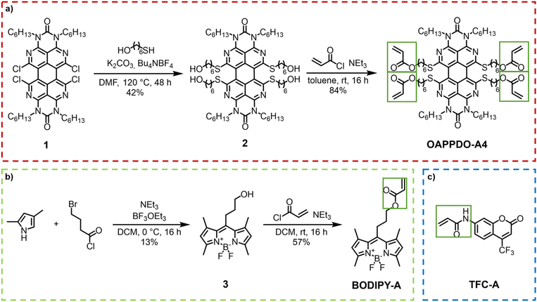 | ||
| Fig. 2 (a) Synthesis of the red emitter OAPPDO-A4. (b) Synthesis of the green emitter BODIPY-A. (c) Blue emitter TFC-A. | ||
Boron dipyrromethene difluoride (BODIPY) derivatives exhibit notable green emission properties and have attracted much attention as fluorescent probes in various applications due to their unique properties.20 For our purposes, we prepared a photopolymerizable BODIPY derivative in a two-step process (Fig. 2b). First, the condensation of 2,4-dimethylpyrrol and 4-bromobutanoyl chloride was performed to obtain an unstable dipyrromethene hydrochloride salt intermediate, which was converted in situ to compound 3 by reaction with BF3·OEt2. The photopolymerizable acrylate was introduced via a subsequent functionalization of the alcohol with acryloyl chloride to yield BODIPY-A.19,21
As a blue emitter, we chose the coumarin derivative 7-[4-(trifluoromethyl)coumarin]-acrylamide (TFC-A), which is commercially available (Fig. 2c).
As a next step, the three RGB polymerizable dyes, OAPPDO-A4, BODIPY-A, and TFC-A, were studied in terms of one photon absorption, emission, and two photon absorption properties to gain further insights into their suitability for 2PLP (Fig. 3 and Table 1).
| Dye | λ abs,max [nm] | ε λ,max [M−1 cm−1] | λ em,max [nm] | Φ [%] | 0–0 transition [nm] | Stokes shift [cm−1] | σ 2 (780 nm) [GM] |
|---|---|---|---|---|---|---|---|
| OAPPDO-A4 | 531 | 17![[thin space (1/6-em)]](https://www.rsc.org/images/entities/char_2009.gif) 245 245 |
565 | 75 | 549 | 1133 | 190 |
| BODIPY-A | 502 | 76![[thin space (1/6-em)]](https://www.rsc.org/images/entities/char_2009.gif) 378 378 |
515 | 88 | 507 | 503 | 17 |
| TFC-A | 344 | 20![[thin space (1/6-em)]](https://www.rsc.org/images/entities/char_2009.gif) 594 594 |
411 | 6 | 383 | 4739 | 4 |
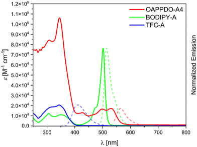
OAPPDO-A4 exhibits an intense absorption band in the UV region and a less intense band in the visible region (until 600 nm), with absorption maxima at 344 nm and 531 nm, respectively. In contrast, BODIPY-A displays a weaker absorption in the UV regime and an intense peak with a maximum at 502 nm. As expected, the relevant absorption of TFC-A was observed at lower wavelength with a maximum at 344 nm. Importantly, none of the three compounds have a significant absorption at NIR region, especially at the wavelength of the laser used for printing (λ = 780 nm), making them suitable for 2PLP.
The emission properties were also studied in solution. As stated above, emission at different wavelengths was targeted, in order to cover the RGB wavelength range and ultimately achieve multi-color emissive structures. OAPPDO-A4 exhibited an emission maximum at the longest wavelength with a maximum at 565 nm, followed by BODIPY-A at 515 nm (green region) and TFC-A at 411 nm (blue region). Furthermore, the quantum yields obtained for OAPPDO-A4 and BODIPY-A, were 70% and 88%, respectively proving them efficient and bright emitters, while a lower quantum yield of 6% was derived for TFC-A. The one photon absorption and emission properties of the emitters were also characterized in the solvent applied during 2PLP (see ESI†).
To further characterize the dyes, two-photon absorption measurements of the RGB dyes were carried out using the Z-scan technique (for further information see ESI†). The two-photon absorption cross sections for TFC-A and BODIPY-A are small (4 and 17 GM, respectively) at the printing wavelength. However, for OAPPDO-A4, this value is slightly higher and may be attributed to a more extended π-system but also to a different environment (DMSO vs. o-xylene) that may influence the two-photon absorption cross section. The two-photon cross section of the employed photoinitiator, BAPO, was also measured (4 GM in DMSO and 53 GM in o-xylene) and the values are in agreement with the literature data.22 Thus, we believe that dyes do not significantly affect the two-photon polymerization process (see next section).
Formulation and 3D printing
The next step was the development of suitable printing formulations for 2PLP and the integration of the synthesized emitters. A standard formulation typically includes a multi-functional acrylate (crosslinker), a photoinitiator, as well as additional additives such as solvents or fillers. In this study, polyethylene glycol diacrylate (PEGDA) and pentaerythritol triacrylate (PETA) were chosen as hydrophilic and hydrophobic crosslinkers, respectively. Both crosslinkers have been widely used in printable materials for 2PLP.1,23 Phenyl-bis-(2,4,6-trimethylbenzoyl)-phosphinoxide (BAPO) was chosen as a photoinitiator due to its low auto-fluorescence, avoiding the “competition” with the selected emitters.24 A key aspect of this work was the incorporation of the polymerizable RGB emitters, while keeping a homogenous formulation. Due to the low solubility of the emitters in the typical crosslinkers, additional solvent was required, which for the sake of good printability was limited to a maximum of 20 wt% in the final formulation. A solution of the emitter mixture in a suitable solvent was prepared and added to a mixture of crosslinker (PETA or PEGDA) and photoinitiator (BAPO 2 wt%). o-Xylene was found to be a suitable solvent for OAPPDO-A4, while TFC-A and BODIPY-A exhibited better solubility in DMSO. High boiling point solvents were chosen to avoid evaporation during the printing process leading to precipitation and reproducibility issues. In order to incorporate as many functional units as possible in the printed structures, highly concentrated solutions were prepared, which depended on the solubility of each dye in the solvent: 6.1 wt% (1.0 mol%) for OAPPDO-A4 in o-xylene, 5.3 wt% (3.1 mol%) for BODIPY-A, and 3.6 wt% (2.7 mol%) TFC-A in DMSO. The final composition of the formulations are shown in Table 2.| Crosslinker | Photoinitiator | Emitter | Solvent | |
|---|---|---|---|---|
| [wt%; mol%] | BAPO [wt%; mol%] | [wt%; mol%] | [wt%; mol%] | |
| Ref1 | PETA 78.0; 57.7 | 2.1; 1.1 | — | o-xylene 19.9; 41.2 |
| Ref2 | PETA 78.0; 50.3 | 2.2; 1.0 | — | DMSO 19.8; 48.7 |
| Red | PETA 79.0; 63.9 | 2.2; 1.3 | OAPPDO-A4 3.9; 0.7 | o-xylene 14.9; 34.2 |
| Green | PETA 78.1; 51.0 | 2.2; 1.0 | BODIPY-A 0.6; 0.3 | DMSO 19.1; 47.7 |
| Blue | PETA 77.7; 52.6 | 2.2; 1.1 | TFC-A 3.0; 2.1 | DMSO 17.1; 44.2 |
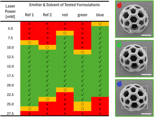
As a next step, the printability of the RGB formulations were tested using a commercially available printer (Photonic Professional GT2, Nanoscribe GmbH). In particular, the optimal printing parameters, especially the laser power (LP), were optimized for each formulation as well as for reference formulations without emitter Ref1 and Ref2 (Table 2). For this purpose, arrays of buckyball-shaped microstructures (16 μm × 16 μm × 15 μm) were printed by varying the LP from 3.75 mW to 27.5 mW and using a constant scan speed of 2 mm s−1 and imaged using scanning electron microscopy (SEM) to visualize the details (Fig. 4). It should be noted that due to printability limitations (especially when printing high microstructures) with formulations containing PEGDA, we decided to focus on the formulations based on PETA. The results were color coded as follows: red, when we were not able to print a defined buckyball, either because the LP was too low to induce the photopolymerization or the LP was too high generating microbubbles that distorted the printed structures. Entries in yellow indicate the observation of structures whose quality was not optimal, e.g. they collapsed due to an insufficient crosslinking density, or they were overexposed leading to loss in resolution. Finally, the green entries represent microstructures without defects, thus defining the printability range. When comparing the printability range for the different formulations, we could observe several interesting effects. First, the solvent plays a role as formulations containing o-xylene (Ref 1) were found to be printable in a wider range, compared to the formulation containing DMSO (Ref 2) (see ESI†). Furthermore, the incorporation of dyes also shifted the necessary LP to create defined 3D microstructures. When printing the red formulation containing OAPPDO-A4, less power was required than for the formulation without the dye (Ref 1); suggesting a possible energy transfer of the OAPPDO-A4 to the photoinitiator. The green and blue formulations containing BODIPY-A and TFC-A, respectively, and DMSO as a solvent, performed differently. While the green formulation exhibited similar printability to the reference (Ref 2), the blue formulation could be printed at much lower LP (5.00 mW), indicating that TFC-A might act as a photosensitizer during the initiation process.
To investigate whether the emitter influenced the printing resolution, arrays of 10 parallel lines with different distances in between them, ranging from 0.2 μm up to 1.0 μm (increments of 0.1 μm), were printed (min LP 5 mW; min scan speed 0.5 mm s−1) and inspected by SEM microscopy (see details in the ESI†). The resolution of the fabricated structures can be defined as the minimum distance of two printed lines next to each other that remain resolved. For the red formulation, a resolution of 187 nm and a minimum line thickness of 200 nm were obtained, whereas a resolution of 233 nm and a minimal feature size of 204 nm were observed for the green formulation. Similar results were obtained for the formulation with the blue emitter showing a resolution of 211 nm and line thickness of 211 nm. These results are very similar to the resolution and minimal feature size obtained for Ref1 (resolution 0.213 μm; min feature size 0.248 μm) Ref2 (resolution 210 μm; min feature size 0.223 μm) and thus indicated that the dyes had no negative impact on the resolution or minimal feature size of the printed microstructures.
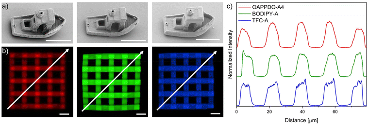
After optimizing the printing parameters and confirming that the dyes do not affect the resolution, other 3D complex geometries such as the benchmark structure “benchy”25 or 3D lattices (55 μm × 55 μm × 16 μm) were printed with the three RGB formulations to prove the versatility of the approach (Fig. 5). Furthermore, confocal microscopy was employed to demonstrate both the emission in solid state at the expected region as well as the incorporation of the three dyes, OAPPDO-A4, BODIPY-A, and TFC-A in the fabricated 3D microstructures. They exhibited emission at the three targeted regions as can be seen in the confocal microscope images (Fig. 5b). To prove the homogeneous distribution, the emission intensities were recorded and plotted against the distance in diagonal (see arrow) (Fig. 5c). The similar height for all local maxima and local minima in the intensity plot for the RGB emitters clearly demonstrated that the distribution of the emitter was homogeneous throughout the entire 3D microstructure for all three cases.
Multicolored emissive 3D microstructures
One advantage of 2PLP is the possibility to use different printable materials sequentially to manufacture complex multi-material structures with high resolution. Thus, once the methodology for the 3D microstructures emitting one color had been established, the next step was the transition towards multi-material 3D printing to obtain microstructures, which emitted light in different colors. To achieve this, a multi-step strategy including sequential printing steps was applied, in which each formulation was used to fabricate specific parts. After all features of the structure of a given color were printed, the formulation needed to be removed via the development procedure and the next formulation was applied in the subsequent step. This process was repeated for each different material. Since the sample had to be removed from the printer for each step, a very precise alignment was necessary to print the next part of the structure in another color in order to avoid a systematic offset.The first demonstrator consisted of a pixel display. The chosen pattern was the shape of a polyaromatic molecule (SFB 1249 logo) with three different colors. For this purpose, four different formulations were needed: one formulation containing no emitter for fabrications of “dark” pixels relative to their fluorescent counterparts and three formulations containing the mentioned RGB emitters to generate the pattern. The pixels themselves were printed micropillars, 1 μm in diameter and 4 μm in height. An array of 35 × 21 pixels was 3D printed using the four materials with a distance of 2 μm in between the pixels.
A confocal microscope was used to image the resulting pattern. Fig. 6b depicts the combined images recorded with the red, green, and blue channel showing the printed pillars. The uniformity of the pixels and successful alignment was also confirmed via SEM imaging (Fig. 6c). Printing pixels in the mentioned dimension would result in an image consisting of 8466 pixels per inch. This is 41 times more pixel per inch compared to a modern 4K screen, but every pixel has a defined color and brightness.
This system was clearly not limited to high resolution printing of simple structures, but also the fabrication of complex multi-material structures appeared possible. To exploit this capability, we selected a second demonstrator consisting of a non-fluorescence cube with different shapes encoded at the different heights, as a simple example for an anti-counterfeiting device. In Fig. 7a a schematic representation of a z-stack multi-material print is shown, the blue spade, green clubs and red diamond are printed at different heights and were separated by 2 μm. The colorful motives are surrounded by a solid scaffold printed with the non-emissive formulation. After subsequent 3D printing using the four formulations, confocal microscopy was used to image the planes and to extract the information encoded inside the 3D structures. Fig. 7b depicts clearly the encoded shapes emitting at different colors (for SEM image see ESI†).
Conclusion
In this work, RGB emitters based on an octaazaperopyrenedioxide (OAPPDO) as well as boron dipyrromethene difluoride (BODIPY) and coumarin derivatives were successfully functionalized with photopolymerizable groups and employed for the fabrication of emissive 3D microstructures using 2PLP. By specific selection of the emitter, we showed that defined emissive microstructures with tunable brightness could be manufactured. Furthermore, we fabricated two demonstrators consisting of a high resolution pixel pattern and a 3D microstructure encoding images in 3D to illustrate the viability of this technology in various applications, such as displays and anti-counterfeiting systems. These promising results will be expanded by broadening the library of available emitters suitable for 2PLP, especially the use of efficient red and blue emitters, opening up new opportunities for this technology in the future.Experimental section
Materials
All chemicals and solvents were purchased from commercial suppliers and used without further purification. Solvents were dried according to standard procedures. Deuterated solvents were bought from Euriso Top or Sigma–Aldrich and used as received.Synthesis of the polymerizable red emitter
OAPPDO 1 was synthesized according to literature.17,18![[thin space (1/6-em)]](https://www.rsc.org/images/entities/char_2009.gif) :
:![[thin space (1/6-em)]](https://www.rsc.org/images/entities/char_2009.gif) 1, then EE) to obtain OAPPDO 2 as a red solid (61 mg, 49 μmol, 42%). 1H NMR (600 MHz, CDCl3, rt) δ = 4.30–4.21 (m, CH2, 8H), 3.60 (t, J = 6.7 Hz, CH2, 8H), 3.36–3.31 (m, CH2, 4H), 3.28–3.23 (m, CH2, 4H), 1.81–1.76 (m, CH2, 8H), 1.75–1.68 (m, CH2, 8H), 1.56–1.52 (m, CH2, 8H), 1.50–1.41 (m, CH2, 16H), 1.39–1.32 (m, CH2, 24H), 0.90 (t, J = 7.0 Hz, CH3, 12H) ppm. 13C NMR (151 MHz, CDCl3, rt) δ = 153.9 (Cq) 151.2 (Cq), 147.1 (Cq), 143.7 (Cq), 113.6 (Cq), 98.4 (Cq), 63.0 (CH2), 42.9 (CH2), 32.8 (CH2), 32.7 (CH2), 31.9 (CH2), 29.9 (CH2), 29.2 (CH2), 27.7 (CH2), 27.1 (CH2), 25.7 (CH2), 22.9 (CH2), 14.3 (CH3) ppm. MALDI HRMS: m/z calcd for C66H104N8O6S4 [M]+: 1232.6956, found: 1232.6940.
1, then EE) to obtain OAPPDO 2 as a red solid (61 mg, 49 μmol, 42%). 1H NMR (600 MHz, CDCl3, rt) δ = 4.30–4.21 (m, CH2, 8H), 3.60 (t, J = 6.7 Hz, CH2, 8H), 3.36–3.31 (m, CH2, 4H), 3.28–3.23 (m, CH2, 4H), 1.81–1.76 (m, CH2, 8H), 1.75–1.68 (m, CH2, 8H), 1.56–1.52 (m, CH2, 8H), 1.50–1.41 (m, CH2, 16H), 1.39–1.32 (m, CH2, 24H), 0.90 (t, J = 7.0 Hz, CH3, 12H) ppm. 13C NMR (151 MHz, CDCl3, rt) δ = 153.9 (Cq) 151.2 (Cq), 147.1 (Cq), 143.7 (Cq), 113.6 (Cq), 98.4 (Cq), 63.0 (CH2), 42.9 (CH2), 32.8 (CH2), 32.7 (CH2), 31.9 (CH2), 29.9 (CH2), 29.2 (CH2), 27.7 (CH2), 27.1 (CH2), 25.7 (CH2), 22.9 (CH2), 14.3 (CH3) ppm. MALDI HRMS: m/z calcd for C66H104N8O6S4 [M]+: 1232.6956, found: 1232.6940.
![[thin space (1/6-em)]](https://www.rsc.org/images/entities/char_2009.gif) :
:![[thin space (1/6-em)]](https://www.rsc.org/images/entities/char_2009.gif) EA 9
EA 9![[thin space (1/6-em)]](https://www.rsc.org/images/entities/char_2009.gif) :
:![[thin space (1/6-em)]](https://www.rsc.org/images/entities/char_2009.gif) 1) was utilized. 300 to 500 ppm of BHT were added to the pure product, which was obtained as a red solid (84% 98.0 mg, 67.6 μmol). 1H NMR (500 MHz, CDCl3, rt) δ = 6.37 (dd, J = 17.4, 1.5 Hz, CH, 4H), 6.09 (dd, J = 17.4, 10.4 Hz, CH, 4H), 5.80 (dd, J = 10.4, 1.5 Hz, CH, 4H), 4.25 (q, J = 7.5 Hz, CH2, 8H), 4.11 (t, J = 6.7 Hz, CH2, 8H), 3.29 (t, J = 7.4 Hz, CH2, 8H), 1.78 (p, J = 7.7 Hz, CH2, 8H), 1.70 (q, J = 7.7 Hz, CH2, 8H), 1.64 (p, J = 6.8 Hz, CH2, 8H), 1.50–1.32 (m, CH2, 40H), 0.90 (t, J = 7.2 Hz, CH3, 12H) ppm. 13C NMR (126 MHz, CDCl3, rt) δ = 166.4 (Cq), 153.8 (Cq), 151.1 (Cq), 147.1 (Cq), 143.7 (Cq), 130.7 (CH2), 128.6 (CH), 113.5 (Cq), 98.3 (Cq), 64.9 (CH2), 42.9 (CH2), 32.6 (CH2), 31.8 (CH2), 29.9 (CH2), 29.1 (CH2), 28.7 (CH2), 27.7 (CH2), 27.0 (CH2), 25.8 (CH2), 22.9 (CH2), 14.2 (CH3) ppm. MALDI HRMS: m/z calcd for C78H112N8O10S8 [M]+: 1448.7384, found: 1448.7349.
1) was utilized. 300 to 500 ppm of BHT were added to the pure product, which was obtained as a red solid (84% 98.0 mg, 67.6 μmol). 1H NMR (500 MHz, CDCl3, rt) δ = 6.37 (dd, J = 17.4, 1.5 Hz, CH, 4H), 6.09 (dd, J = 17.4, 10.4 Hz, CH, 4H), 5.80 (dd, J = 10.4, 1.5 Hz, CH, 4H), 4.25 (q, J = 7.5 Hz, CH2, 8H), 4.11 (t, J = 6.7 Hz, CH2, 8H), 3.29 (t, J = 7.4 Hz, CH2, 8H), 1.78 (p, J = 7.7 Hz, CH2, 8H), 1.70 (q, J = 7.7 Hz, CH2, 8H), 1.64 (p, J = 6.8 Hz, CH2, 8H), 1.50–1.32 (m, CH2, 40H), 0.90 (t, J = 7.2 Hz, CH3, 12H) ppm. 13C NMR (126 MHz, CDCl3, rt) δ = 166.4 (Cq), 153.8 (Cq), 151.1 (Cq), 147.1 (Cq), 143.7 (Cq), 130.7 (CH2), 128.6 (CH), 113.5 (Cq), 98.3 (Cq), 64.9 (CH2), 42.9 (CH2), 32.6 (CH2), 31.8 (CH2), 29.9 (CH2), 29.1 (CH2), 28.7 (CH2), 27.7 (CH2), 27.0 (CH2), 25.8 (CH2), 22.9 (CH2), 14.2 (CH3) ppm. MALDI HRMS: m/z calcd for C78H112N8O10S8 [M]+: 1448.7384, found: 1448.7349.
Synthesis of the polymerizable green emitter
![[thin space (1/6-em)]](https://www.rsc.org/images/entities/char_2009.gif) :
:![[thin space (1/6-em)]](https://www.rsc.org/images/entities/char_2009.gif) 1 to hexane/EA 7
1 to hexane/EA 7![[thin space (1/6-em)]](https://www.rsc.org/images/entities/char_2009.gif) :
:![[thin space (1/6-em)]](https://www.rsc.org/images/entities/char_2009.gif) 3 to hexane/EA 1
3 to hexane/EA 1![[thin space (1/6-em)]](https://www.rsc.org/images/entities/char_2009.gif) :
:![[thin space (1/6-em)]](https://www.rsc.org/images/entities/char_2009.gif) 1). The pure product was obtained after recrystallization from CHCl3/hexane as an orange crystalline solid (13%, 172 mg, 562 μmol). 1H NMR (301 MHz, CDCl3, rt) δ = 6.05 (s, CH, 2H), 3.81 (t, J = 6.0 Hz, CH2, 2H), 3.13–3.02 (m, CH2 2H), 2.51 (d, J = 1.4 Hz, CH3, 6H), 2.44 (s, CH3, 6H), 1.92–1.82 (m, CH2, 2H) ppm. EI HRMS: m/z calcd for C16H21BF2N2O [M]+: 306.1710, found: 306.1712.
1). The pure product was obtained after recrystallization from CHCl3/hexane as an orange crystalline solid (13%, 172 mg, 562 μmol). 1H NMR (301 MHz, CDCl3, rt) δ = 6.05 (s, CH, 2H), 3.81 (t, J = 6.0 Hz, CH2, 2H), 3.13–3.02 (m, CH2 2H), 2.51 (d, J = 1.4 Hz, CH3, 6H), 2.44 (s, CH3, 6H), 1.92–1.82 (m, CH2, 2H) ppm. EI HRMS: m/z calcd for C16H21BF2N2O [M]+: 306.1710, found: 306.1712.
![[thin space (1/6-em)]](https://www.rsc.org/images/entities/char_2009.gif) :
:![[thin space (1/6-em)]](https://www.rsc.org/images/entities/char_2009.gif) CH2Cl2 2
CH2Cl2 2![[thin space (1/6-em)]](https://www.rsc.org/images/entities/char_2009.gif) :
:![[thin space (1/6-em)]](https://www.rsc.org/images/entities/char_2009.gif) 1 to 1
1 to 1![[thin space (1/6-em)]](https://www.rsc.org/images/entities/char_2009.gif) :
:![[thin space (1/6-em)]](https://www.rsc.org/images/entities/char_2009.gif) 2). 300 to 500 ppm of BHT were added to the pure product, which was obtained as an orange solid (57%, 30.0 mg, 83.3 μmol). 1H NMR (400 MHz, CDCl3, rt) δ = 6.42 (dd, J = 17.2, 1.5 Hz, CH, 1H), 6.13 (dd, J = 17.2, 10.5 Hz, CH, 1H), 6.06 (s, CH, 2H), 5.87 (dd, J = 10.5, 1.5 Hz, CH, 1H), 4.32 (t, J = 6.1 Hz, CH2, 2H), 3.11–3.05 (m, CH2 2H), 2.52 (s, CH3 6H), 2.43 (s, CH3, 6H), 2.05–1.98 (m, CH2, 2H) ppm. 13C NMR (101 MHz, CDCl3, rt) δ = 166.04 (Cq), 154.31 (Cq), 144.78 (Cq), 140.22 (Cq), 131.37 (Cq), 131.16 (CH2), 128.12 (CH), 121.86 (CH), 121.82 (CH), 77.21 (Cq), 63.97 (CH2), 30.78 (CH2), 25.17 (CH2), 16.37 (CH3), 14.46 (CH3) ppm. EI HRMS: m/z calcd for C19H23BF2N2O2 [M]+: 360.1821, found: 360.1821.
2). 300 to 500 ppm of BHT were added to the pure product, which was obtained as an orange solid (57%, 30.0 mg, 83.3 μmol). 1H NMR (400 MHz, CDCl3, rt) δ = 6.42 (dd, J = 17.2, 1.5 Hz, CH, 1H), 6.13 (dd, J = 17.2, 10.5 Hz, CH, 1H), 6.06 (s, CH, 2H), 5.87 (dd, J = 10.5, 1.5 Hz, CH, 1H), 4.32 (t, J = 6.1 Hz, CH2, 2H), 3.11–3.05 (m, CH2 2H), 2.52 (s, CH3 6H), 2.43 (s, CH3, 6H), 2.05–1.98 (m, CH2, 2H) ppm. 13C NMR (101 MHz, CDCl3, rt) δ = 166.04 (Cq), 154.31 (Cq), 144.78 (Cq), 140.22 (Cq), 131.37 (Cq), 131.16 (CH2), 128.12 (CH), 121.86 (CH), 121.82 (CH), 77.21 (Cq), 63.97 (CH2), 30.78 (CH2), 25.17 (CH2), 16.37 (CH3), 14.46 (CH3) ppm. EI HRMS: m/z calcd for C19H23BF2N2O2 [M]+: 360.1821, found: 360.1821.
Methods
![[thin space (1/6-em)]](https://www.rsc.org/images/entities/char_2009.gif) :
:![[thin space (1/6-em)]](https://www.rsc.org/images/entities/char_2009.gif) 1 base formulation
1 base formulation![[thin space (1/6-em)]](https://www.rsc.org/images/entities/char_2009.gif) :
:![[thin space (1/6-em)]](https://www.rsc.org/images/entities/char_2009.gif) emitter solvent mixture) and again sonicated for 30 min at 50 °C. The formulations were always used within 24 h.
emitter solvent mixture) and again sonicated for 30 min at 50 °C. The formulations were always used within 24 h.
![[thin space (1/6-em)]](https://www.rsc.org/images/entities/char_2009.gif) :
:![[thin space (1/6-em)]](https://www.rsc.org/images/entities/char_2009.gif) Pd (80
Pd (80![[thin space (1/6-em)]](https://www.rsc.org/images/entities/char_2009.gif) :
:![[thin space (1/6-em)]](https://www.rsc.org/images/entities/char_2009.gif) 20). Images were processed using ImageJ.
20). Images were processed using ImageJ.
Author contributions
The manuscript was written through contributions of all authors. All authors have given approval to the final version of the manuscript.Data availability
Data for this article, including raw data of the characterization of the materials and images are available at HeiData repository at https://doi.org/10.11588/data/JTWFKX.Conflicts of interest
There is no conflict to declare.Acknowledgements
The authors acknowledge support by German Research Foundation (DFG) within the framework of SFB1249 and the Excellence Cluster “3D Matter Made to Order” (EXC-2082/1-390761711). The authors also acknowledge access to the Nikon Imaging Center at Heidelberg University. We thank Prof. Dr R. Schröder, Dr I. Wagner, and R. Curticean for the access and training to the SEM facilities. The authors also acknowledge L. Brüchle, Prof. Dr M. Kivala as well as H. B. D. Tran, C. Vazquez-Martel, Dr O. Eivgi and Dr C.A. Spiegel for their support and fruitful discussions.References
- S. C. Ligon, R. Liska, J. Stampfl, M. Gurr and R. Mülhaupt, Chem. Rev., 2017, 117, 10212 CrossRef CAS PubMed.
- A. Bagheri and J. Jin, ACS Appl. Polym. Mater., 2019, 1, 593 CrossRef CAS.
- (a) L. Yang, A. Münchinger, M. Kadic, V. Hahn, F. Mayer, E. Blasco, C. Barner-Kowollik and M. Wegener, Adv. Opt. Mater., 2019, 7, 1901040 CrossRef CAS; (b) P. Kiefer, V. Hahn, M. Nardi, L. Yang, E. Blasco, C. Barner-Kowollik and M. Wegener, Adv. Opt. Mater., 2020, 8, 2000895 CrossRef CAS; (c) L. Guan, C. Cao, X. Liu, Q. Liu, Y. Qiu, X. Wang, Z. Yang, H. Lai, Q. Sun and C. Ding, et al. , Nat. Commun., 2024, 15, 2387 CrossRef CAS PubMed; (d) M. Carlotti and V. Mattoli, Small, 2019, 15, e1902687 CrossRef PubMed; (e) C. Barner-Kowollik, M. Bastmeyer, E. Blasco, G. Delaittre, P. Müller, B. Richter and M. Wegener, Angew. Chem., Int. Ed., 2017, 56, 15828 CrossRef CAS PubMed; (f) J. Fischer, J. B. Mueller, J. Kaschke, T. J. A. Wolf, A.-N. Unterreiner and M. Wegener, Opt. Express, 2013, 21, 26244 CrossRef PubMed.
- (a) P. Mainik, C. A. Spiegel and E. Blasco, Adv. Mater., 2023, 2310100 Search PubMed; (b) Y. Yang, X. Song, X. Li, Z. Chen, C. Zhou, Q. Zhou and Y. Chen, Adv. Mater., 2018, e1706539 CrossRef PubMed; (c) Y.-G. Park, I. Yun, W. G. Chung, W. Park, D. H. Lee and J.-U. Park, Adv. Sci., 2022, 9, e2104623 CrossRef PubMed; (d) F. Kotz, K. Arnold, W. Bauer, D. Schild, N. Keller, K. Sachsenheimer, T. M. Nargang, C. Richter, D. Helmer and B. E. Rapp, Nature, 2017, 544, 337 CrossRef CAS PubMed.
- C. A. Spiegel, M. Hippler, A. Münchinger, M. Bastmeyer, C. Barner–Kowollik, M. Wegener and E. Blasco, Adv. Funct. Mater., 2020, 30, 1907615 CrossRef CAS.
- A. Salehi, X. Fu, D.-H. Shin and F. So, Adv. Funct. Mater., 2019, 29, 1808803 CrossRef.
- S. Rani, R. K. Das, A. Jaiswal, G. P. Singh, A. Palwe, S. Saxena and S. Shukla, J. Chem. Eng., 2023, 454, 140130 CrossRef CAS.
- S.-W. Huang Chen, C.-C. Shen, T. Wu, Z.-Y. Liao, L.-F. Chen, J.-R. Zhou, C.-F. Lee, C.-H. Lin, C.-C. Lin and C.-W. Sher, et al. , Photonics Res., 2019, 7, 416 CrossRef.
- (a) H.-Y. Lin, C.-W. Sher, D.-H. Hsieh, X.-Y. Chen, H.-M. P. Chen, T.-M. Chen, K.-M. Lau, C.-H. Chen, C.-C. Lin and H.-C. Kuo, Photonics Res., 2017, 5, 411 CrossRef CAS; (b) L. Yang, F. Mayer, U. H. F. Bunz, E. Blasco and M. Wegener, Light: Adv. Manuf., 2021, 2, 1 Search PubMed; (c) M. Gastaldi, F. Cardano, M. Zanetti, G. Viscardi, C. Barolo, S. Bordiga, S. Magdassi, A. Fin and I. Roppolo, ACS Mater. Lett., 2021, 3, 1 CrossRef CAS; (d) J. Y. E. Chan, Q. Ruan, M. Jiang, H. Wang, H. Wang, W. Zhang, C.-W. Qiu and J. K. W. Yang, Nat. Commun., 2021, 12, 3728 CrossRef CAS PubMed.
- J. Bae, S. Lee, J. Ahn, J. H. Kim, M. Wajahat, W. S. Chang, S.-Y. Yoon, J. T. Kim, S. K. Seol and J. Pyo, ACS Nano, 2020, 14, 10993 CrossRef CAS PubMed.
- (a) L. Shi, L. Meng, F. Jiang, Y. Ge, F. Li, X. Wu and H. Zhong, Adv. Funct. Mater., 2019, 29, 1903648 CrossRef; (b) T. Xuan, S. Shi, Le Wang, H.-C. Kuo and R.-J. Xie, J. Phys. Chem. Lett., 2020, 11, 5184 CrossRef CAS PubMed; (c) B. H. Kim, M. S. Onses, J. B. Lim, S. Nam, N. Oh, H. Kim, K. J. Yu, J. W. Lee, J.-H. Kim and S.-K. Kang, et al. , Nano Lett., 2015, 15, 969 CrossRef CAS PubMed.
- (a) F. Mayer, S. Richter, P. Hübner, T. Jabbour and M. Wegener, Adv. Mater. Technol., 2017, 2, 1700212 CrossRef; (b) H. Liu, J. Xu, H. Wang, Y. Liu, Q. Ruan, Y. Wu, X. Liu and J. K. W. Yang, Adv. Mater., 2019, 31, e1807900 CrossRef PubMed.
- F. Mayer, S. Richter, J. Westhauser, E. Blasco, C. Barner-Kowollik and M. Wegener, Sci. Adv., 2019, 5, eaau9160 CrossRef CAS PubMed.
- (a) A. Concellón, A. P. H. J. Schenning, P. Romero, M. Marcos and J. L. Serrano, Macromolecules, 2018, 51, 2349 CrossRef; (b) J. Monti, A. Concellón, R. Dong, M. Simmler, A. Münchinger, C. Huck, P. Tegeder, H. Nirschl, M. Wegener and C. O. Osuji, et al. , ACS Appl. Mater. Interfaces, 2022, 14, 33746 CrossRef CAS PubMed; (c) J. Scrimgeour, D. N. Sharp, C. F. Blanford, O. M. Roche, R. G. Denning and A. J. Turberfield, Adv. Mater., 2006, 18, 1557 CrossRef CAS; (d) H.-B. Sun, T. Tanaka, K. Takada and S. Kawata, Appl. Phys. Lett., 2001, 79, 1411 CrossRef CAS; (e) T. Abele, T. Messer, K. Jahnke, M. Hippler, M. Bastmeyer, M. Wegener and K. Göpfrich, Adv. Mater., 2022, 34, e2106709 CrossRef PubMed; (f) A. I. Maydykovskiy, E. A. Mamonov, N. V. Mitetelo, S. Soria and T. V. Murzina, JETP Lett., 2022, 115, 261 CrossRef CAS.
- R. Eichelmann, J. Monti, L.-Y. Hsu, F. Kröger, J. Ballmann, E. Blasco and L. H. Gade, Mol. Syst. Des. Eng., 2023, 8, 1470 RSC.
- M. Hertzog, R. Eichelmann, P. Jeudy, T. Wesp, J. Ballmann, S. Settele, F. L. Sebastian, A. Mischok, F. Le Roux and F. Tenopala-Carmona, et al. , J. Mater. Chem. C, 2024, 12, 2745 RSC.
- T. Wesp, T. Bruckhoff, H. Wadepohl and L. H. Gade, Chem. – Eur. J., 2022, 28, e202201706 CrossRef CAS PubMed.
- R. Eichelmann, P. Jeudy, L. Schneider, J. Zerhoch, P. R. Mayer, J. Ballmann, F. Deschler and L. H. Gade, Org. Lett., 2024, 26, 1172 CrossRef CAS PubMed.
- E. Lestini, L. D. Blackman, C. M. Zammit, T. Chen, R. J. Williams, M. Inam, B. Couturaud and R. K. O'Reilly, Polym. Chem., 2018, 9, 820 RSC.
- (a) P. de Bonfils, L. Péault, P. Nun and V. Coeffard, Eur. J. Org. Chem., 2021, 1809 CrossRef CAS; (b) M. Poddar and R. Misra, Coord. Chem. Rev., 2020, 421, 213462 CrossRef CAS; (c) Y. Qin, X. Liu, P.-P. Jia, L. Xu and H.-B. Yang, Chem. Soc. Rev., 2020, 49, 5678–5703 RSC.
- (a) Z. Lu, L. Mei, X. Zhang, Y. Wang, Y. Zhao and C. Li, Polym. Chem., 2013, 4, 5743 RSC; (b) A. Loudet and K. Burgess, Chem. Rev., 2007, 107, 4891 CrossRef CAS PubMed; (c) M. Daerr, J. Pabel, G. Höfner, P. Mayer and K. T. Wanner, Med. Chem. Res., 2020, 29, 301 CrossRef CAS; (d) Y. Zhang, Y. Yu, G. Li, X. Zhang, Z. Wu and L. Lin, Biomacromolecules, 2021, 22, 2020 CrossRef CAS PubMed.
- (a) B. Li, J. Lalevée, L. M. Mazur, K. Matczyszyn, S. Ravaine and S. Jradi, Addit. Manuf., 2023, 75, 103741 CAS; (b) K. J. Schafer, J. M. Hales, M. Balu, K. D. Belfield, E. W. Van Stryland and D. J. Hagan, J. Photochem. Photobiol., A, 2004, 162, 497 CrossRef CAS.
- (a) Y. Jia, C. A. Spiegel, A. Welle, S. Heißler, E. Sedghamiz, M. Liu, W. Wenzel, M. Hackner, J. P. Spatz and M. Tsotsalas, et al. , Adv. Funct. Mater., 2023, 33, 2207826 CrossRef CAS; (b) R. Royo, P. Mainik, C. Benitez-Martin, R. Andreu, E. Blasco, F. Najera and B. Villacampa, Adv. Mater. Technol., 2023, 8, 2300571 CrossRef CAS.
- P. Kiefer, V. Hahn, M. Nardi, L. Yang, E. Blasco, C. Barner-Kowollik and M. Wegener, Adv. Opt. Mater., 2020, 8, 2000895 CrossRef CAS.
- S. N. Sanders, T. H. Schloemer, M. K. Gangishetty, D. Anderson, M. Seitz, A. O. Gallegos, R. C. Stokes and D. N. Congreve, Nature, 2022, 604, 474 CrossRef CAS PubMed.
Footnote |
| † Electronic supplementary information (ESI) available. See DOI: https://doi.org/10.1039/d4lp00141a |
| This journal is © The Royal Society of Chemistry 2024 |

