Mechanism of CO2 in promoting the hydrogenation of levulinic acid to γ-valerolactone catalyzed by RuCl3 in aqueous solution†
Han-Yun
Min
 a,
Jin-Shan
Xiong
 a,
Ting-Hao
Liu
 a,
Shuai
Fu
 a,
Chang-Wei
Hu
 b and
Hua-Qing
Yang
 *a
*a
aCollege of Chemical Engineering, Sichuan University, Chengdu, Sichuan 610065, P. R. China. E-mail: huaqingyang@scu.edu.cn; Fax: +86 28 85464466; Tel: +86 28 85464466
bKey Laboratory of Green Chemistry and Technology, Ministry of Education, College of Chemistry, Sichuan University, Chengdu, Sichuan 610064, P. R. China
First published on 29th April 2024
Abstract
A Ru-containing complex shows good catalytic performance toward the hydrogenation of levulinic acid (LA) to γ-valerolactone (GVL) with the assistance of organic base ligands (OBLs) and CO2. Herein, we report the competitive mechanisms for the hydrogenation of LA to GVL, 4-oxopentanal (OT), and 2-methyltetrahydro-2,5-furandiol (MFD) with HCOOH or H2 as the H source catalyzed by RuCl3 in aqueous solution at the M06/def2-TZVP, 6-311++G(d,p) theoretical level. Kinetically, the hydrodehydration of LA to GVL is predominant, with OT and MFD as side products. With HCOOH as the H source, initially, the OBL (triethylamine, pyridine, or triphenylphosphine) is responsible for capturing H+ from HCOOH, leading to HCOO− and [HL]+. Next, the Ru3+ site is in charge of sieving H− from HCOO−, yielding [RuH]2+ hydride and CO2. Alternatively, with H2 as the H source, the OBL stimulates the heterolysis of H–H bond with the aid of Ru3+ active species, producing [RuH]2+ and [HL]+. Toward the [RuH]2+ formation, H2 as the H source exhibits higher activity than HCOOH as the H source in the presence of an OBL. Thereafter, H− in [RuH]2+ gets transferred to the unsaturated C site of ketone carbonyl in LA. Afterwards, the Ru3+ active species is capable of cleaving the C–OH bond in 4-hydroxyvaleric acid, yielding [RuOH]2+ hydroxide and GVL. Subsequently, CO2 promotes Ru–OH bond cleavage in [RuOH]2+, forming HCO3− and regenerating the Ru3+-active species owing to its Lewis acidity. Lastly, between the resultant HCO3− and [HL]+, a neutralization reaction occurs, generating H2O, CO2, and OBLs. Thus, the present study provides insights into the promotive roles of additives such as CO2 and OBLs in Ru-catalyzed hydrogenation.
1. Introduction
Currently, with the rapid consumption of fossil resources, tremendous efforts are directed towards converting renewable biomass into fuels and value-added chemicals.1 Carbohydrates, one of the major components of plant biomass, can be selectively dehydrated into levulinic acid (LA), which is a very attractive C5 platform chemical because of its characteristic carboxyl (–COOH) and carbonyl (–C![[double bond, length as m-dash]](https://www.rsc.org/images/entities/char_e001.gif) O) groups.2 In particular, the hydrogenation of LA to γ-valerolactone (GVL) has become increasingly attractive3–6 since GVL can be widely used as a highly effective fuel additive, food additive, green solvent, and intermediate for biobased polymers.7–9
O) groups.2 In particular, the hydrogenation of LA to γ-valerolactone (GVL) has become increasingly attractive3–6 since GVL can be widely used as a highly effective fuel additive, food additive, green solvent, and intermediate for biobased polymers.7–9
To date, both heterogeneous and homogeneous catalysts have been widely used in the selective hydrogenation of LA to GVL. Heterogeneous catalysts, i.e., Ru-,9–14 Pt-,15 Fe-,16 Co-,17 Ni-,18 and Cu-based catalysts,16,19 exhibit good activity for LA hydrogenation. Compared with heterogeneous catalysts, homogeneous catalysts, including Ru-,20–24 Ir-,25–27 Pt-,28 and Ni-containing complexes,5,29 have higher catalytic efficiency and selectivity under mild reaction conditions. Noteworthily, Ru-containing complexes show excellent catalytic performance. Interestingly, Fu's group has pioneeringly conducted research on the hydrogenation of LA to GVL catalyzed by RuCl3·3H2O with organic base ligands using HCOOH or H2 as the hydrogen (H) source in aqueous solution.20 With H2 as the H source, CO2 addition can greatly improve Ru-catalyzed hydrogenation; however, CO2 acts as a decomposition product with HCOOH as the H source.20 Notably, supercritical CO2 is also used as a medium for LA-to-GVL hydrogenation in heterogeneous catalytic systems.30 However, this striking positive effect of CO2 on Ru-catalyzed hydrogenation at the molecular level remains unclear.
In this work, we aim to theoretically explore the molecular mechanism underlying the hydrogenation of LA to GVL catalyzed by RuCl3 with an organic base ligand in aqueous solution using HCOOH or H2 as the H source. The objectives are as follows: (a) to ascertain the catalytically active species of RuCl3·3H2O in aqueous solution, (b) to clarify the difference in the reduction mechanism between HCOOH and H2 as the H source, (c) to elucidate the role of organic base ligands, and (d) to understand the origin of the promotive effect of CO2 in Ru-catalyzed hydrogenation.
2. Computational methods
In an aqueous solution, all geometric calculations were performed using the program Gaussian 09.31 A polarizable continuum model based on solute electron density (PCM-SMD) was applied to simulate the solvent effect of the aqueous solution.32,33 Full geometry optimizations were carried out to locate all the stationary points and transition states via a hybrid M06 functional method34 with the def2-TZVP basis set35 and the corresponding effective core potential (ECP) for the Ru element; the 6-311++G(d,p) basis set36,37 for C, H, O, N, and P elements in the reaction region; and the 6-31G(d,p) basis set38 for C and H elements of the phenyl group, namely M06/def2-TZVP, 6-311++G(d,p).Harmonic frequency calculations were employed to verify the stationary points and obtain corrections of the zero-point energy (ZPE) as well as the thermal correction of the Gibbs free energy (G0). For reaction pathway analysis, each transition structure was verified to have only one imaginary frequency, and the connections between transition states and corresponding intermediates were verified through intrinsic reaction coordinate (IRC) calculations.39,40 The natural charges were gained using natural bond orbital (NBO) analysis.41,42 The differential electron localization function of species was analyzed by using the Multiwfn package.43,44 Unless otherwise specified, the Gibbs free energy of formation (ΔG) is relative to the initial catalytically active species and reactants obtained at the M06/6-311++G(d,p), def2-TZVP level in the aqueous solution under experimental temperature and pressure (423 K and 80 atm).20
The rate constants were assessed over the 403–443 K temperature range, on the basis of conventional transition state theory, together with tunneling correction, as described in our previous study.45,46
3. Results and discussion
In LA, there are two kinds of carbonyl groups, i.e., ketone carbonyl and carboxyl carbonyl. Then, the hydrogenations of these carbonyl groups are competitive with each other. For the hydrogenation of LA with HCOOH or H2 as the H source, the possible reaction pathways are depicted in Scheme 1.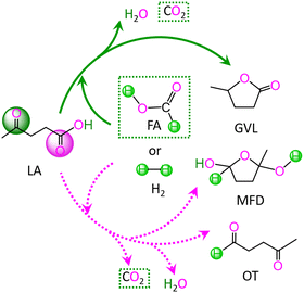 | ||
| Scheme 1 Reaction pathway for the conversion of levulinic acid (LA) to γ-valerolactone (GVL), 2-methyltetrahydro-2,5-furandiol (MFD) and 4-oxopentanal (OT) with HCOOH and H2 as the H source. | ||
As depicted in Scheme 1, with HCOOH as the H source, reaction (I) is associated with the hydrodehydration of LA to GVL through ketone carbonyl, reaction (II) is concerned with the hydrodehydration of LA to 4-oxopentanal (OT) through carboxyl carbonyl, and reaction (III) is related to the hydrogenation of LA to 2-methyltetrahydro-2,5-furandiol (MFD) through carboxyl carbonyl. Alternatively, with H2 as the H source, reaction IV denotes the hydrodehydration of LA to GVL through ketone carbonyl, reaction V signifies the hydrodehydration of LA to OT through carboxyl carbonyl, and reaction VI expresses the hydrogenation of LA to MFD through carboxyl carbonyl. These six gross reactions (I)–(VI) are listed as follows:
| LA + HCOOH → GVL + H2O + CO2 | (I) |
| LA + HCOOH → OT + H2O + CO2 | (II) |
| LA + HCOOH → MFD + CO2 | (III) |
| LA + H2 → GVL + H2O | (IV) |
| LA + H2 → OT + H2O | (V) |
| LA + H2 → MFD | (VI) |
3.1 Ru-containing active species of RuCl3·3H2O in aqueous solution
In aqueous solution, RuCl3·3H2O should dissociate into Ru3+ cation and Cl− anion. Here, the ground state of Ru3+ cation is the sextet state, with the quartet state and doublet state as the excited states, which locate 214.5 and 421.8 kJ mol−1 above the ground sextet state, respectively, as shown in Fig. S1 from the ESI.† The superscript prefixes “2”, “4”, and “6” represent the doublet, quartet, and sextet states, respectively. Unless specified, the default state is the singlet ground state “1”. Based on the experimental literature in aqueous solution,20 additives are associated with organic base ligands (OBLs), i.e., triphenylphosphine (PPh3), triethylamine (NEt3), and pyridine (PY). After that, H2O, PPh3, NEt3, and PY may coordinate to the Ru3+-center. Thereupon, we will discuss the stabilities of coordinated Ru-containing species in aqueous solution thermodynamically.As shown in Fig. S1 from ESI,† initially, the coordination of H2O to the 6Ru3+-center is calculated to be thermodynamically unfavorable. That is to say, when RuCl3·3H2O dissolves in aqueous solution, Ru3+ cation does not coordinate with solvent water molecules. Considering the coordination of the ligand to 6Ru3+-center in aqueous solution, the values of Gr are −16.1, 8.2, 12.1, and 22.0 kJ mol−1, for 6[Ru(PPh3)]3+, 6[Ru(NEt3)]3+, 6[Ru(H2O)]3+, and 6[Ru(PY)]3+ complexes, respectively, as shown in Fig. S2 from ESI.† Among the four ligands of PPh3, NEt3, H2O, and PY, only PPh3 can coordinate to the 6Ru3+-center, forming a stable complex 6[Ru(PPh3)]3+. Thereupon, 6[Ru(PPh3)]3+ is preferred as the initial catalytically active species.
3.2 Reaction I: LA + HCOOH → GVL + H2O + CO2
With HCOOH as the hydrogen source, the hydrodehydration of LA to GVL includes the following five reaction stages, i.e.,| HCOOH + L → HCOO− + [HL]+ (L = PPh3, NEt3, and PY) | (i) |
| HCOO− + 6[Ru(PPh3)]3+ → 6[RuH]2+ + PPh3 + CO2 | (ii) |
| 6[RuH]2+ + LA → 6[RuOH]2+ + GVL | (iii) |
| 6[RuOH]2+ + CO2 + PPh3 → 6[Ru(PPh3)]3+ + HCO3− | (iv) |
| HCO3− + [HL]+ → L + CO2 + H2O (L = PPh3, NEt3, and PY) | (v) |
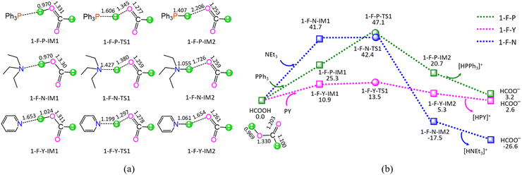
As shown in Fig. 1, the ΔGs of reaction stage (i) of HCOOH + L → HCOO− + [HL]+ (L = PPh3, NEt3, and PY) are 3.2, −26.6, and 2.6 kJ mol−1, respectively, while ΔEs are calculated to be 1.0, −28.5, and 1.8 kJ mol−1. It is inferred that the NEt3 ligand is thermodynamically favourable, whereas both PPh3 and PY are thermodynamically unfavourable, grabbing the proton H+ from HCOOH. On the other hand, kinetically, reaction stage (i) comprises three typical reaction steps, i.e., (1) the formation of a molecular complex between HCOOH and ligand, (2) the proton-exchange via a three-membered linear transition state (TS), and (3) the dissociation of the resultant products (HCOO− + [HL]+). The 1-F-P includes an energy height of the highest point (EHHP) of 47.1 kJ mol−1 at 1-F-P-TS1 and the highest energy requirement (HER) of 25.3 kJ mol−1 at the reaction step of (HCOOH + PPh3) → 1-F-P-IM1. The 1-F-N involves the EHHP of 42.4 kJ mol−1 at 1-F-N-TS1 and the HER of 41.7 kJ mol−1 at the reaction step of (HCOOH + NEt3) → 1-F-N-IM1. The 1-F-Y contains the EHHP of 13.5 kJ mol−1 at 1-F-Y-TS1 and the HER of 10.9 kJ mol−1 at the reaction step of (HCOOH + PY) → 1-F-Y-IM1. It is indicated that these ligands kinetically increase as PPh3 < NEt3 < PY in capturing the proton H+ from HCOOH, because of their corresponding EHHP of 47.1, 42.4, and 13.5 kJ mol−1. One can conclude that NEt3 ligand should be preferable in grabbing the proton H+ from HCOOH both thermodynamically and kinetically. This result is in good agreement with the experimental observation, in which the additive NEt3 plays an excellently promotive role in the Ru-catalyzed hydrogenation of LA to GVL.20
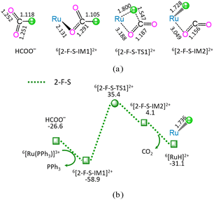
As shown in Fig. 2, the reaction stage (ii) of HCOO− + 6[Ru(PPh3)]3+ → 6[RuH]2+ + PPh3 + CO2 comprises three typical reaction steps, i.e., (1) the ligand–exchange between the 6[Ru(PPh3)]3+ complex and HCOO− anion, forming a 6[2-F-S-IM1]2+ complex, (2) both C–H bond cleavage and Ru–H bond formation via a four-membered cyclic 6[2-F-S-TS1]2+ through a [1,3]-H-shift, yielding a molecular complex 6[2-F-S-IM2]2+, and (3) the dissociation of 6[2-F-S-IM2]2+, producing both 6[RuH]2+ hydride and free CO2. The 2-F-S involves the EHHP of 35.4 kJ mol−1 at 6[2-F-S-TS1]2+ and HER of 94.3 kJ mol−1 at the reaction step of 6[2-F-S-IM1]2+ → 6[2-F-S-TS1]2+ → 6[2-F-S-IM2]2+.
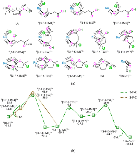
As shown in Fig. 3, the 3-F-K comprises seven successive reaction steps, i.e., (1) the formation of a molecular complex 6[3-F-K-IM4]2+ through the initial interaction of Ru-site with ketone carbonyl of LA, (2) a [2 + 2] addition at ketone carbonyl via four-membered cyclic 6[3-F-K-TS2]2+ through a [1,3]-H shift with Ru–H bond cleavage, (3) the molecular rearrangement between 6[3-F-K-IM5]2+ and 6[3-F-K-IM6]2+, (4) the ring-closure with C1–O bond formation via a seven-membered envelope 6[3-F-K-TS3]2+, (5) the molecular rearrangement between 6[3-F-K-IM7]2+ and 6[3-F-K-IM8]2+, (6) the formation of GVL with both C1–OH bond cleavage and Ru–OH bond formation through four-membered cyclic 6[3-F-K-TS4]2+, and (7) the release of GVL from 6[3-F-K-IM9]2+, leaving 6[RuOH]2+ hydroxide behind. The 3-F-K includes the EHHP of 56.3 kJ mol−1 at 6[3-F-K-TS2]2+ and HER of 76.1 kJ mol−1 at the reaction step of 6[3-F-K-IM6]2+ → 6[3-F-K-TS3]2+ → 6[3-F-K-IM7]2+ for the ring-closure with C1–O bond formation.
Additionally, between 3-F-C and 3-F-K, the reaction pathway differs from (6[RuH]2+ + LA) to 6[3-F-K-IM6]2+, whereas the remaining reaction pathways from 6[3-F-K-IM6]2+ to (6[RuOH]2+ + GVL) are identical to each other. The 3-F-C from (6[RuH]2+ + LA) to 6[3-F-K-IM6]2+ involves two reaction steps, i.e., (1) the formation of a molecular complex 6[3-F-C-IM4]2+ through the initial interaction of Ru-site with the carboxyl carbonyl of LA, and (2) a [2 + 5] addition at ketone carbonyl via seven-membered cyclic 6[3-F-C-TS2]2+ through a [1,6]-H shift with Ru–H bond cleavage. The 3-F-C possesses the EHHP of 68.6 kJ mol−1 at 6[3-F-C-TS2]2+ and HER of 76.1 kJ mol−1 at the reaction step of 6[3-F-K-IM6]2+ → 6[3-F-K-TS3]2+ → 6[3-F-K-IM7]2+ for the ring-closure with C1–O bond formation.
Compared with 3-F-C, 3-F-K is kinetically more favorable, owing to its lower EHHP (56.3 vs. 68.6 kJ mol−1). That is to say, for reaction stage (iii), the optimal reaction pathway kinetically proceeds through the initial interaction of Ru-site with ketone carbonyl rather than carboxyl carbonyl.
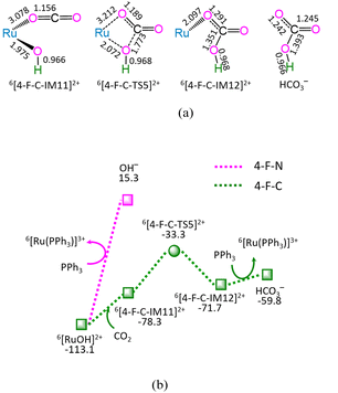
As depicted in Fig. 4, in the absence of CO2 (marked as 4-F-N), the ligand–exchange between 6[RuOH]2+ and PPh3 requires the energy of 128.4 kJ mol−1, producing 6[Ru(PPh3)]3+ and OH− anion. Alternatively, the 4-F-C comprises three successive reaction steps, i.e., (1) the formation of a molecular complex 6[4-F-C-IM11]2+, (2) both Ru–OH bond cleavage and C–OH bond formation via four-membered cyclic 6[4-F-C-TS5]2+, and (3) the ligand–exchange between 6[4-F-C-IM12]2+ and PPh3, yielding HCO3− and regenerating catalytically active species 6[Ru(PPh3)]3+. The 4-F-C contains the EHHP of −33.3 kJ mol−1 at 6[4-F-C-TS5]2+ and the HER of 45.0 kJ mol−1 at the reaction step of 6[4-F-C-IM11]2+ → 6[4-F-C-TS5]2+ → 6[4-F-C-IM12]2+ for the Ru–OH bond cleavage and C–OH bond formation.
Compared with 4-F-N, 4-F-C is kinetically more preferable, thanks to its lower EHHP (−33.3 vs. 15.3 kJ mol−1) and its lower HER (45.0 vs. 128.4 kJ mol−1). This embodies that CO2 facilitates the Ru–OH bond cleavage in [RuOH]2+ hydroxide, owing to its Lewis-acidity.
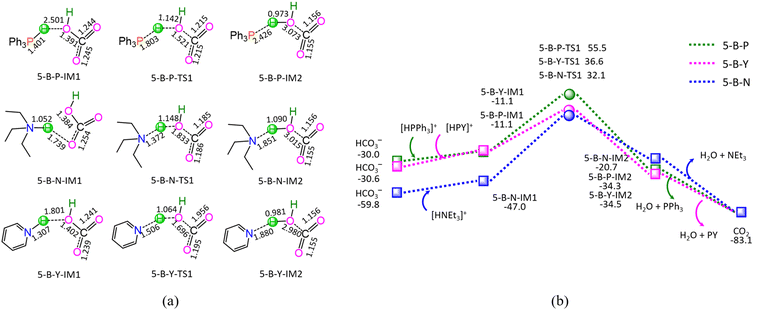
As shown in Fig. 5, the ΔG of reaction stage (v) of HCO3− + [HL]+ → L + CO2 + H2O (L = PPh3, NEt3, and PY) is −53.1, −23.3, and −52.5 kJ mol−1, respectively. It is indicated that the neutralization reaction of reaction stage (v) is thermodynamically favorable. Alternatively, reaction stage (v) is composed of three typical reaction steps, i.e., (1) the formation of a molecular complex between HCO3− and [HL]+, (2) the formation of H2O between HCO3− Brønsted base and [HL]+ Brønsted acid via a three-membered linear TS, and (3) the dissociation of the resultant products (L + CO2 + H2O). The 5-B-P includes the EHHP of 55.5 kJ mol−1 at 5-B-P-TS1 and the HER of 66.6 kJ mol−1 at the reaction step of 5-B-P-IM1 → 5-B-P-TS1 → 5-B-P-IM2. The 5-B-N involves the EHHP of 32.1 kJ mol−1 at 5-B-N-TS1 and HER of 79.1 kJ mol−1 at the reaction step of 5-B-N-IM1 → 5-B-N-TS1 → 5-B-N-IM2. The 5-B-Y contains the EHHP of 36.6 kJ mol−1 at 5-B-Y-TS1 and the HER of 47.7 kJ mol−1 at the reaction step of 5-B-Y-IM1 → 5-B-Y-TS1 → 5-B-Y-IM2. It is indicated that these [HL]+ kinetically increased as [HPPh3]+ < [HPY]+ < [HNEt3]+ in neutralizing HCO3−.
Based on the above results, for the reaction I of LA + HCOOH → GVL + H2O + CO2 catalyzed by 6[Ru(PPh3)]3+ with the additive NEt3, the minimal energy reaction pathway (MERP) is made up of five reaction stages, i.e., 1-F-N, 2-F-S, 3-F-K, 4-F-C, and 5-B-N, namely, GR-I. The GR-I possesses the EHHP of 56.3 kJ mol−1 at 6[3-F-K-TS2]2+ and the HER of 94.3 kJ mol−1 at the reaction step of 6[2-F-S-IM1]2+ → 6[2-F-S-TS1]2+ → 6[2-F-S-IM2]2+ for the C–H bond cleavage of HCOO−.
3.3 Reaction II: LA + HCOOH → OT + H2O + CO2
The hydrodehydration of LA to OT with HCOOH as the hydrogen source comprises the aforementioned four reaction stages, i.e., (i), (ii), (iv), and (v), and the following reaction stage (vi),| 6[RuH]2+ + LA → 6[RuOH]2+ + OT | (vi) |
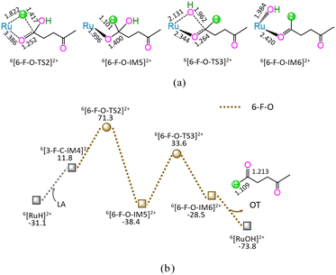
As shown in Fig. 6, the 6-F-O includes four successive reaction steps, i.e., (1) the formation of a molecular complex 6[3-F-C-IM4]2+ through the initial interaction of Ru-site with the carboxyl carbonyl of LA, (2) a [2 + 2] addition at carboxyl carbonyl via four-membered cyclic 6[6-F-O-TS2]2+ through a [1,3]-H shift with Ru–H bond cleavage, (3) the formation of OT with C1–OH bond cleavage through four-membered cyclic 6[6-F-O-TS3]2+, and (4) the release of OT from 6[6-F-O-IM6]2+, leaving 6[RuOH]2+ hydroxide behind. The 6-F-O involves the EHHP of 71.3 kJ mol−1 at 6[6-F-O-TS2]2+ for the Ru–H bond cleavage and HER of 72.0 kJ mol−1 at the reaction step of 6[6-F-O-IM5]2+ → 6[6-F-O-TS3]2+ → 6[6-F-O-IM6]2+ for the C1–OH bond cleavage.
As mentioned earlier, for the reaction II of LA + HCOOH → OT + H2O + CO2 catalyzed by 6[Ru(PPh3)]3+ with the additive NEt3, the MERP is composed of five reaction stages, i.e., 1-F-N, 2-F-S, 6-F-O, 4-F-C, and 5-B-N, namely GR-II. The GR-II comprises the EHHP of 71.3 kJ mol−1 at 6[6-F-O-TS2]2+ for the Ru–H bond cleavage and the HER of 94.3 kJ mol−1 at the reaction step of 6[2-F-S-IM1]2+ → 6[2-F-S-TS1]2+ → 6[2-F-S-IM2]2+ for the C–H bond cleavage of HCOO−.
3.4 Reaction III: LA + HCOOH → MFD + CO2
The hydrogenation of LA to MFD with HCOOH as the hydrogen source includes the aforementioned two reaction stages, i.e., (i) and (ii), and the following reaction stage (vii),| 6[RuH]2+ + LA + [HNEt3]+ + PPh3 → 6[Ru(PPh3)]3+ + NEt3 + MFD | (vii) |
As depicted in Fig. 7, the 7-F-M comprises seven successive reaction steps, i.e., (1) the formation of a molecular complex 6[3-F-C-IM4]2+, (2) a [2 + 2] addition at carboxyl carbonyl, (3) the molecular rearrangement between 6[6-F-O-IM5]2+ and 6[7-F-M-IM6]2+, (4) the ring-closure with C4–O bond formation via a seven-membered envelope 6[7-F-M-TS3]2+, (5) the ligand–exchange between 6[7-F-M-IM7]2+ and PPh3, regenerating the catalytically active species 6[Ru(PPh3)]3+, (6) the formation of a molecular complex 7-F-M-IM9 between [7-F-M-IM8]− and [HNEt3]+, (7) the proton-exchange between [7-F-M-IM8]− and [HNEt3]+via a three-membered linear 7-F-M-TS4, yielding a molecular complex 7-F-M-IM10, and (8) the dissociation of F-M-IM10 into free NEt3 and MFD.
As mentioned earlier, for the reaction III of LA + HCOOH → MFD + CO2 catalyzed by 6[Ru(PPh3)]3+ with the additive NEt3, the MERP is composed of three reaction stages, i.e., 1-F-N, 2-F-S, and 7-F-M, namely, GR-III. The GR-III involves the EHHP of 85.2 kJ mol−1 at 6[F-M-TS4]2+ and HER of 98.7 kJ mol−1 at the reaction step of 6[7-F-M-IM7]2+ + PPh3 → [7-F-M-IM8]− + 6[Ru(PPh3)]3+ for the regeneration of the catalytically active species 6[Ru(PPh3)]3+.
3.5 Reaction IV: LA + H2 → GVL + H2O
With H2 as the hydrogen source, the hydrodehydration of LA to GVL includes the following sequential reaction stages (viii), (iii), (iv), and (v),| 6[Ru(PPh3)]3+ + H2 + L → 6[RuH]2+ + [HL]+ + PPh3 | (viii) |
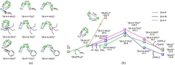
As shown in Fig. 8, at the beginning, the ligand–exchange takes place between 6[Ru(PPh3)]3+ and H2 molecule, forming a molecular complex 6[Ru(H2)]3+ and free PPh3. From 6[Ru(H2)]3+, the H–H bond of H2 undergoes homolysis, yielding a 6[Ru(H)2]3+ dihydride with the energy demand of 403.7 kJ mol−1. Such a high requirement of 403.7 kJ mol−1 makes H–H bond homolysis nearly impossible.
On the other hand, when the organic base ligand (L = PPh3, NEt3, and PY) participates in the H–H bond cleavage of 6[Ru(H2)]3+, the H–H bond of H2 undergoes heterolysis via a four-membered U-type TS, producing a 6[RuH]2+ hydride and [HL]+ cation. The ΔG of reaction stage (viii) of 6[Ru(PPh3)]3+ + H2 + L → 6[RuH]2+ + [HL]+ + PPh3 (L = PPh3, NEt3, and PY) is 13.9, −15.9, and 13.3 kJ mol−1, respectively. It is indicated that the NEt3 ligand is thermodynamically favourable, whereas both PPh3 and PY are thermodynamically unfavourable. Kinetically, the 8-H-P, 8-H-N, and 8-H-Y include the EHHP of 88.8, 101.1, and 118.4 kJ mol−1, and the HER of 51.5, 44.6, and 49.1 kJ mol−1, respectively. It is inferred that the promotive effect of the ligands kinetically increases as PY < NEt3 < PPh3 in the H–H bond heterolysis, because of their corresponding EHHPs of 118.4 > 101.1 > 88.8 kJ mol−1. One can see that NEt3 ligand should be preferable in the H–H bond heterolysis both thermodynamically and kinetically. Obviously, compared with the 403.7 kJ mol−1 for the H–H bond homolysis, these organic base ligands (L = PPh3, NEt3, and PY) remarkably decrease the energy requirement for the H–H bond cleavage in 6[Ru(H2)]3+, because of their very lower EHHPs (88.8, 101.1, and 118.4 kJ mol−1).
As mentioned earlier, for the reaction IV of LA + H2 → GVL + H2O catalyzed by 6[Ru(PPh3)]3+ with the additive NEt3, the MERP is made up of four reaction stages, i.e., 8-H-N, 3-F-K, 4-F-C, and 5-B-N, namely, GR-IV. The GR-IV possesses the EHHP of 101.1 kJ mol−1 at 6[8-H-N-TS1]3+ for the H–H bond heterolysis, and HER of 79.1 kJ mol−1 at the reaction step of 5-B-N-IM1 → 5-B-N-TS1 → 5-B-N-IM2 for the neutralization reaction between HCO3− Brønsted base and [HL]+ Brønsted acid. Furthermore, this result from 4-F-C echoes that the additive CO2 prominently promotes the Ru-OH bond cleavage of 6[RuOH]2+, due to its Lewis acidity. Thereupon, this can explain why adding CO2 can greatly improve the Ru-catalyzed hydrogenation with H2 as the H source.20
3.6 Reaction V: LA + H2 → OT + H2O
For the reaction V of LA + H2 → OT + H2O catalyzed by 6[Ru(PPh3)]3+ with the additive NEt3, the MERP is composed of four sequential reaction stages, i.e., 8-H-N, 6-F-O, 4-F-C, and 5-B-N, namely, GR-V. The GR-V comprises the EHHP of 101.1 kJ mol−1 at 6[8-H-N-TS1]3+ for the H–H bond heterolysis, and HER of 79.1 kJ mol−1 at the reaction step of 5-B-N-IM1 → 5-B-N-TS1 → 5-B-N-IM2 for the neutralization reaction between HCO3− Brønsted base and [HL]+ Brønsted acid.3.7 Reaction VI: LA + H2 → MFD
For the reaction VI of LA + H2 → MFD catalyzed by 6[Ru(PPh3)]3+ with the additive NEt3, the MERP includes two reaction stages, i.e., 8-H-N and 7-F-M, namely, GR-VI. The GR-VI involves the EHHP of 101.1 kJ mol−1 at 6[8-H-N-TS1]3+ for the H–H bond heterolysis, and HER of 98.7 kJ mol−1 at the reaction step of 6[7-F-M-IM7]2+ + PPh3 → [7-F-M-IM8]− + 6[Ru(PPh3)]3+ for the regeneration of the catalytically active species 6[Ru(PPh3)]3+.3.8 Comparison of HCOOH with H2 as the H-Source
As mentioned earlier, for the hydrogenation of LA with HCOOH or H2 as the H source, their reaction pathways differ in the formed stage of 6[RuH]2+ hydride, i.e., reaction stages (1-F-n + 2-F-S) with HCOOH as the H source, and reaction stage (8-H-N) with H2 as the H source, whereas their reaction pathways after 6[RuH]2+ hydride are identical. With HCOOH as the H source, the MERP for the formation of 6[RuH]2+ hydride is associated with the reaction stages of both (i) (L = NEt3) and (ii), namely, P-HCOOH. Besides, with H2 as the H source, the MERP for the formation of 6[RuH]2+ hydride is concerned with reaction stage (viii) (L = NEt3), namely, P-H2. Thereupon, we will kinetically compare the following reaction pathways, i.e.,| 6[Ru(PPh3)]3+ + HCOOH + NEt3 → 6[RuH]2+ + [HNEt3]+ + PPh3 + CO2 (P-HCOOH) |
| 6[Ru(PPh3)]3+ + H2 + NEt3 → 6[RuH]2+ + [HNEt3]+ + PPh3 (P-H2) |
In P-HCOOH, the rate-determining step is associated with 6[2-F-S-IM1]2+ → 6[2-F-S-TS1]2+ → 6[2-F-S-IM2]2+ for the C–H bond cleavage and Ru–H bond formation. The corresponding rate constants kP-HCOOH can be adapted by the following expressions (in s−1):
kP-HCOOH = 2.80 × 10¹³ exp(−97![[thin space (1/6-em)]](https://www.rsc.org/images/entities/char_2009.gif) 523/RT) 523/RT) | (1) |
Alternatively, in P–H2, the rate-determining step is concerned with 6[8-H-N-IM1]3+ → 6[8-H-N-TS1]3+ → 6[8-H-N-IM2]3+ for the H–H bond heterolysis and Ru–H bond formation. The corresponding rate constants can be described by the following expression (in s−1):
kP-H2 = 4.17 × 10¹⁴ exp(−56![[thin space (1/6-em)]](https://www.rsc.org/images/entities/char_2009.gif) 892/RT) 892/RT) | (2) |
The rate constants of kP-H2 are computed to be about 5 orders of magnitude larger than those of kP-HCOOH, over the temperature range 403–443 K. It is indicated that H2 as the H source exhibits higher activity than HCOOH as the H source toward the formation of 6[RuH]2+ hydride from 6[Ru(PPh3)]3+.
3.9 Origin of Selectively Generating GVL instead of OT and MFD
kP-OT = 3.33 × 10¹² exp(−68![[thin space (1/6-em)]](https://www.rsc.org/images/entities/char_2009.gif) 457/RT) 457/RT) | (3) |
kP-MFD = 5.00 × 10¹⁰ exp(−39![[thin space (1/6-em)]](https://www.rsc.org/images/entities/char_2009.gif) 136/RT) 136/RT) | (4) |
The rate constants of kP-MFD are computed to be about 94–42 times larger than that of kP-OT, over the temperature range 403–443 K. In view of kP-MFD and kP-OT, their selectivities for P-MFD and P-OT are calculated to be 99.0–97.7% and 1.0∼2.3%, respectively. It is inferred that P-MFD is major, whereas P-OT is minor.
![[double bond, length as m-dash]](https://www.rsc.org/images/entities/char_e001.gif) O and P-COOH. As shown in Fig. 3, 6, and 7, the selectivity-controlling steps are concerned with 6[RuH]2+ + LA → 6[3-F-K-TS2]2+ → 6[3-F-K-IM5]2+ for the C4–H bond formation in P-C
O and P-COOH. As shown in Fig. 3, 6, and 7, the selectivity-controlling steps are concerned with 6[RuH]2+ + LA → 6[3-F-K-TS2]2+ → 6[3-F-K-IM5]2+ for the C4–H bond formation in P-C![[double bond, length as m-dash]](https://www.rsc.org/images/entities/char_e001.gif) O, and 6[RuH]2+ + LA → 6[6-F-O-TS2]2+ → 6[6-F-O-IM5]2+ for the C1–H bond formation in P-COOH. The corresponding rate constants of kP-C
O, and 6[RuH]2+ + LA → 6[6-F-O-TS2]2+ → 6[6-F-O-IM5]2+ for the C1–H bond formation in P-COOH. The corresponding rate constants of kP-C![[double bond, length as m-dash]](https://www.rsc.org/images/entities/char_e001.gif) O and kP-COOH can be adapted by the following expressions (in s−1 mol−1 dm3):
O and kP-COOH can be adapted by the following expressions (in s−1 mol−1 dm3):kP-C![[double bond, length as m-dash]](https://www.rsc.org/images/entities/char_e001.gif) O = 4.12 × 10⁶ exp(−35 O = 4.12 × 10⁶ exp(−35![[thin space (1/6-em)]](https://www.rsc.org/images/entities/char_2009.gif) 530/RT) 530/RT) | (5) |
kP-COOH = 2.17 × 10⁷ exp(−56![[thin space (1/6-em)]](https://www.rsc.org/images/entities/char_2009.gif) 342/RT) 342/RT) | (6) |
The rate constants of kP-C![[double bond, length as m-dash]](https://www.rsc.org/images/entities/char_e001.gif) O are calculated to be about 94–53 times larger than those of kP-COOH, over the temperature range 403–443 K. Given kP-C
O are calculated to be about 94–53 times larger than those of kP-COOH, over the temperature range 403–443 K. Given kP-C![[double bond, length as m-dash]](https://www.rsc.org/images/entities/char_e001.gif) O and kP-COOH, their selectivities for P-C
O and kP-COOH, their selectivities for P-C![[double bond, length as m-dash]](https://www.rsc.org/images/entities/char_e001.gif) O and P-COOH are computed to be 99.0–98.2% and 1.0–1.8%, respectively. It is indicated that P-C
O and P-COOH are computed to be 99.0–98.2% and 1.0–1.8%, respectively. It is indicated that P-C![[double bond, length as m-dash]](https://www.rsc.org/images/entities/char_e001.gif) O is dominant, whereas P-COOH is secondary.
O is dominant, whereas P-COOH is secondary.
Here, the C–H bond formation is related to the C-site capturing the negatively charged H− from 6[RuH]2+ hydride. In LA, the charge of C4 (+0.314) in the –C![[double bond, length as m-dash]](https://www.rsc.org/images/entities/char_e001.gif) O group is more positive than that of C1 (+0.003) in the –COOH group. Thereupon, the C4-site in the –C
O group is more positive than that of C1 (+0.003) in the –COOH group. Thereupon, the C4-site in the –C![[double bond, length as m-dash]](https://www.rsc.org/images/entities/char_e001.gif) O group more readily captures the negatively charged H− from 6[RuH]2+ hydride than the C1-site in the –COOH group. One can expect that the C4–H bond in P-C
O group more readily captures the negatively charged H− from 6[RuH]2+ hydride than the C1-site in the –COOH group. One can expect that the C4–H bond in P-C![[double bond, length as m-dash]](https://www.rsc.org/images/entities/char_e001.gif) O is more readily formed than the C1–H bond in P-COOH.
O is more readily formed than the C1–H bond in P-COOH.
To visualize the interaction of the forming C–H bond in 6[3-F-K-TS2]2+ from P-C![[double bond, length as m-dash]](https://www.rsc.org/images/entities/char_e001.gif) O and 6[6-F-O-TS2]2+ from P-COOH, the maps of differential electron localization function (DELF) are analyzed in Fig. 9. As depicted in Fig. 9, for the forming C–H bond region, the DELF region (blue and dark color) of 6[3-F-K-TS2]2+ is narrower than that of 6[6-F-O-TS2]2+. It is inferred that the C4–H bond formation in 6[3-F-K-TS2]2+ from P-C
O and 6[6-F-O-TS2]2+ from P-COOH, the maps of differential electron localization function (DELF) are analyzed in Fig. 9. As depicted in Fig. 9, for the forming C–H bond region, the DELF region (blue and dark color) of 6[3-F-K-TS2]2+ is narrower than that of 6[6-F-O-TS2]2+. It is inferred that the C4–H bond formation in 6[3-F-K-TS2]2+ from P-C![[double bond, length as m-dash]](https://www.rsc.org/images/entities/char_e001.gif) O more easily occurs than the C1–H bond formation in 6[6-F-O-TS2]2+ from P-COOH.
O more easily occurs than the C1–H bond formation in 6[6-F-O-TS2]2+ from P-COOH.
4. Conclusion
The reaction mechanism for the hydrogenation of LA to GVL, OT and MFD catalyzed by Ru-containing species with HCOOH or H2 as the hydrogen source in aqueous solution has been theoretically studied. The following conclusions can be drawn from the present results.In aqueous solution with PPh3 as an additive, a stable complex 6[Ru(PPh3)]3+ can be formed after RuCl3·3H2O dissolves. Thereupon, 6[Ru(PPh3)]3+ is preferred as the initial catalytically active species.
Kinetically, the hydrodehydration of LA to GVL is predominant through the hydrogenation of ketone carbonyl, with OT and MFD as side-products through the hydrogenation of carboxyl carbonyl. This stems from the more positive charge of C4 (+0.314) in the –C![[double bond, length as m-dash]](https://www.rsc.org/images/entities/char_e001.gif) O group than that of C1 (+0.003) in the –COOH group in LA. Herein, the C4-site in the –C
O group than that of C1 (+0.003) in the –COOH group in LA. Herein, the C4-site in the –C![[double bond, length as m-dash]](https://www.rsc.org/images/entities/char_e001.gif) O group more easily sieves the negatively charged H− from [RuH]2+ hydride than the C1-site in the –COOH group.
O group more easily sieves the negatively charged H− from [RuH]2+ hydride than the C1-site in the –COOH group.
With HCOOH as the H source, initially, the OBL, e.g., triethylamine, pyridine, or triphenylphosphine, is responsible for grabbing the proton H+ from HCOOH, resulting in both HCOO− and [HL]+. Next, the Ru3+-site undertakes to capture the H− from HCOO−, generating both [RuH]2+ hydride and CO2. Besides, with H2 as the H source, the OBL promotes the heterolytic H–H bond with the aid of Ru3+-active species, yielding both [RuH]2+ hydride and [HL]+. Toward the formation of [RuH]2+ hydride, H2 as the H source displays higher activity than HCOOH as the H source in the presence of an OBL.
And then, the H− in [RuH]2+ hydride transfers to the unsaturated C-site of ketone carbonyl in LA. Afterwards, the Ru3+-active species is responsible for the C–OH bond cleavage in 4-hydroxyvaleric acid, producing both [RuOH]2+ hydroxide and GVL. After that, CO2 promotes the Ru–OH bond cleavage in [RuOH]2+ hydroxide, forming HCO3− and regenerating the Ru3+-active species, because of its Lewis-acidity. Subsequently, neutralization reaction occurs between the resultant HCO3− and [HL]+, yielding H2O, CO2, and OBL.
Author contributions
The manuscript was written through the contributions of all the authors. H.-Y. Min is responsible for the data curation, investigation formal analysis and writing – original draft, J.-S. Xiong, and T.-H. Liu are responsible for formal analysis, S. Fu for data curation, H.-Q. Yang is responsible for the conceptualization, methodology, resources, project administration, formal analysis, supervision and writing – review & editing, and C.-W. Hu is responsible for the supervision and resources. All authors have given approval to the final version of the manuscript.Conflicts of interest
There are no conflicts to declare.Acknowledgements
The authors are grateful for financial support by the National Natural Science Foundation of China (No: 22073064) and the 111 Project (No: B17030).Notes and references
- B. Y. Karlinskii and V. P. Ananikov, Chem. Soc. Rev., 2023, 52, 836–862 RSC.
- M. Sajid, U. Farooq, G. Bary, M. M. Azim and X. B. Zhao, Green Chem., 2021, 23, 9198–9238 RSC.
- Y. W. Shao, K. Sun, Q. Y. Li, Q. H. Liu, S. Zhang, Q. Liu, G. Z. Hu and X. Hu, Green Chem., 2019, 21, 4499–4511 RSC.
- T. Raj, K. Chandrasekhar, R. Banu, J. J. Yoon, G. Kumar and S. H. Kim, Fuel, 2021, 303, 121333 CrossRef CAS.
- C. Q. Deng, J. Liu, J. H. Luo, L. J. Gan, J. Deng and Y. Fu, Angew. Chem., Int. Ed., 2022, 61, e202115983 CrossRef CAS PubMed.
- J. S. Yang, R. D. Shi and G. B. Zhou, Chem. Eng. J., 2023, 475, 146297 CrossRef CAS.
- M. Kondeboina, S. S. Enumula, K. S. Reddy, P. Challa, D. R. Burri and S. R. R. Kamaraju, Fuel, 2021, 285, 119094 CrossRef CAS.
- J. Bai, C. W. Cheng, Y. Liu, C. G. Wang, Y. H. Liao, L. G. Chen and L. L. Ma, Mol. Catal., 2021, 516, 112000 CrossRef CAS.
- E. Soszka, O. Sneka-Płatek, E. Skiba, W. Maniukiewicz, A. Pawlaczyk, J. Rogowski, M. Szynkowska-Jóźwik and A. M. Ruppert, Fuel, 2022, 319, 123646 CrossRef CAS.
- A. M. Ruppert, M. Jędrzejczyk, O. Sneka-Płatek, N. Keller, A. S. Dumon, C. Michel, P. Sautet and J. Grams, Green Chem., 2016, 18, 2014–2028 RSC.
- J. Molleti, M. S. Tiwari and G. D. Yadav, Chem. Eng. J., 2018, 334, 2488–2499 CrossRef CAS.
- Z. Z. Wei, X. F. Li, J. Deng, H. R. Li and Y. Wang, Mol. Catal., 2018, 448, 100–107 CrossRef CAS.
- Y. W. Lu, Y. X. Wang, Y. H. Wang, Q. Cao, X. G. Xie and W. H. Fang, Mol. Catal., 2020, 493, 111097 CrossRef CAS.
- Z. Z. Liu, X. Y. Gao and G. Y. Song, Chem. Eng. J., 2023, 470, 143869 CrossRef CAS.
- N. Siddiqui, C. Pendem, R. Goyal, R. Khatun, T. S. Khan, C. Samanta, K. Chiang, K. Shah, M. A. Haider and R. Bal, Fuel, 2022, 323, 124272 CrossRef CAS.
- T. Y. Deng, L. Yan, X. L. Li and Y. Fu, ChemSusChem, 2019, 12, 3837–3848 CrossRef CAS PubMed.
- J. J. Lu, Y. Wei, K. Y. Lu, C. M. Wu, X. Y. Nong, J. F. Li, C. L. Liu and W. S. Dong, Mol. Catal., 2022, 527, 112409 CrossRef CAS.
- C. C. Li, C. H. Hsieh and Y. C. Lin, Mol. Catal., 2022, 523, 111720 CrossRef CAS.
- Q. Xu, X. L. Li, T. Pan, C. G. Yu, J. Deng, Q. X. Guo and Y. Fu, Green Chem., 2016, 18, 1287–1294 RSC.
- L. Deng, J. Li, D. M. Lai, Y. Fu and Q. X. Guo, Angew. Chem., Int. Ed., 2009, 48, 6529–6532 CrossRef CAS PubMed.
- J. M. Tukacs, B. Fridrich, G. Dibó, E. Székely and L. T. Mika, Green Chem., 2015, 17, 5189–5195 RSC.
- C. Moustani, E. Anagnostopoulou, K. Krommyda, C. Panopoulou, K. G. Koukoulakis, E. B. Bakeas and G. Papadogianakis, Appl. Catal., B, 2018, 238, 82–92 CrossRef CAS.
- C. A. M. R. van Slagmaat and S. M. A. De Wildeman, Eur. J. Inorg. Chem., 2018, 694–702 CrossRef CAS.
- V. S. Shende, A. B. Raut, P. Raghav, A. A. Kelkar and B. M. Bhanage, ACS Omega, 2019, 4, 19491–19498 CrossRef CAS PubMed.
- W. Li, J. H. Xie, H. Lin and Q. L. Zhou, Green Chem., 2012, 14, 2388–2930 RSC.
- J. Deng, Y. Wang, T. Pan, Q. Xu, Q. X. Guo and Y. Fu, ChemSusChem, 2013, 6, 1163–1167 CrossRef CAS PubMed.
- S. D. Wang, V. Dorcet, T. Roisnel, C. Bruneau and C. Fischmeister, Organometallics, 2017, 36, 708–713 CrossRef CAS.
- C. Ortiz-Cervantes, M. Flores-Alamo and J. J. García, ACS Catal., 2015, 5, 1424–1431 CrossRef CAS.
- B. Zada, R. Zhu, B. Wang, J. Liu, J. Deng and Y. Fu, Green Chem., 2020, 22, 3427–3432 RSC.
- W. R. H. Wright and R. Palkovits, ChemSusChem, 2012, 5, 1657–1667 CrossRef CAS PubMed.
- M. J. Frisch, G. W. Trucks, H. B. Schlegel, G. E. Scuseria, M. A. Robb, J. R. Cheeseman, G. Scalmani, V. Barone, B. Mennucci and G. A. E. A. Petersson, Revision C.01, Gaussian Inc., Wallingford, CT, 2010 Search PubMed.
- M. Cossi, G. Scalmani, N. Rega and V. Barone, J. Chem. Phys., 2002, 117, 43–54 CrossRef CAS.
- A. V. Marenich, C. J. Cramer and D. G. Truhlar, J. Phys. Chem. B, 2009, 113, 6378–6396 CrossRef CAS PubMed.
- Y. Zhao and D. G. Truhlar, Theor. Chem. Acc., 2008, 120, 215–241 Search PubMed.
- F. Weigend and R. Ahlrichs, Phys. Chem. Chem. Phys., 2005, 7, 3297 RSC.
- A. D. McLean and G. S. Chandler, J. Chem. Phys., 1980, 72, 5639–5648 CrossRef CAS.
- R. Krishnan, J. S. Binkley, R. Seeger and J. A. Pople, J. Chem. Phys., 1980, 72, 650–654 CrossRef CAS.
- P. C. Hariharan and J. A. Pople, Theor. Chim. Acta, 1973, 28, 213–222 CrossRef CAS.
- C. Gonzalez and H. B. Schlegel, J. Chem. Phys., 1989, 90, 2154–2161 CrossRef CAS.
- C. Gonzalez and H. B. Schlegel, J. Chem. Phys., 1990, 94, 5523–5527 CrossRef CAS.
- A. E. Reed, R. B. Weinstock and F. Weinhold, J. Chem. Phys., 1985, 83, 735–746 CrossRef CAS.
- A. E. Reed, L. A. Curtiss and F. Weinhold, Chem. Rev., 1988, 88, 899–926 CrossRef CAS.
- T. Lu and F. W. Chen, J. Comput. Chem., 2012, 33, 580–592 CrossRef CAS PubMed.
- T. Lu and F. W. Chen, J. Mol. Graphics Modell., 2012, 38, 314–323 CrossRef CAS PubMed.
- L. K. Ren, L. F. Zhu, T. Qi, J. Q. Tang, H. Q. Yang and C. W. Hu, ACS Catal., 2017, 7, 2199–2212 CrossRef CAS.
- B. Xiang, Y. Wang, T. Qi, H. Q. Yang and C. W. Hu, J. Catal., 2017, 352, 586–598 CrossRef CAS.
Footnote |
| † Electronic supplementary information (ESI) available: Geometric structures, data of energies, relative Gibbs free energies. The geometric structures of various species. See DOI: https://doi.org/10.1039/d4cp00753k |
| This journal is © the Owner Societies 2024 |

