Deep-red light-emitting electrochemical cells based on phosphor-sensitized thermally activated delayed fluorescence†
Yin
Chen‡
a,
Yun-Xin
Wang‡
b,
Chin-Wei
Lu
 *b and
Hai-Ching
Su
 *a
*a
aInstitute of Lighting and Energy Photonics, National Yang Ming Chiao Tung University, Tainan 71150, Taiwan. E-mail: haichingsu@nycu.edu.tw; Tel: +886-6-3032121-57792
bDepartment of Applied Chemistry, Providence University, Taichung 43301, Taiwan. E-mail: cwlu@pu.edu.tw; Tel: +886-4-26328001-15213
First published on 12th July 2022
Abstract
Solid-state light-emitting electrochemical cells (LECs) show the advantages of a simple fabrication process, low-voltage operation, and compatibility with inert electrodes. However, even phosphorescent deep-red LECs still suffer from limited device efficiencies. In this work, we demonstrate efficient deep-red LECs based on phosphor-sensitized thermally activated delayed fluorescence (TADF). A phosphorescent ionic transition metal complex (iTMC) is used as the host and a deep-red TADF emitter is employed as the guest. With rapid intersystem crossing (ISC) to promote intramolecular singlet-to-triplet energy transfer in the iTMC, efficient host–guest Förster energy transfer ensures harvesting both singlet and triplet excitons on the host molecules. In addition, the effective reverse intersystem crossing (RISC) process can further recycle the guest triplet excitons coming from the host–guest Dexter energy transfer and direct triplet exciton formation on the guest under electrical excitation. Therefore, host–guest deep-red LECs doped with a 0.25 wt% guest achieve a peak EQE of up to 5.11%, which is among the highest reported for deep-red LECs. Analysis of the device efficiency by evaluating related device parameters implies that more than 73% of the excitons on the guest molecules can be gathered for electroluminescence (EL). It approaches 3× EL efficiency of fluorescent devices, which can only harvest 25% excitons for light emission, and thus confirms an efficient RISC process to recycle the guest triplet excitons. These results reveal that phosphor-sensitized TADF is useful for achieving highly efficient fluorescent deep-red LECs. However, triplet–triplet annihilation on the guest still hinders the improvement of the device efficiency of the phosphor-sensitized TADF LECs when the guest doping concentration or device current is higher.
Introduction
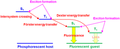
Owing to the unique operation mechanism, solid-state light-emitting electrochemical cells (LECs)1 show several advantages over conventional organic light-emitting diodes (OLEDs). The emissive layer of an LEC contains mobile ionic species, which can be separated under a bias and form accumulated anions and cations at the anode and cathode, respectively. As such, electrochemically doped layers are built at electrodes to promote balanced carrier injection and subsequent efficient radiative carrier recombination in the remaining intrinsic layer, providing low operating voltage and high power efficiency. With only a single emissive layer, an LEC can have a similar function to that of a multilayered OLED. Such a simple device structure can be easily processed from solutions. Furthermore, the electrical characteristics of LECs are insensitive to the work functions of electrodes and the emissive-layer thickness due to electrochemical doping. In contrast to OLEDs, these superior properties enable fancy display applications2–4 and optical optimization by adjusting device thickness to several hundred nanometers.5–8 Easy fabrication processes make LECs a promising alternative technology of cost-effective light-emitting devices for lighting and displays.Since the first demonstration of polymer LECs by Pei et al. in 1995,1 several types of LECs based on conjugated polymers,9,10 ionic transition metal complexes (iTMCs),11–14 small molecules,15,16 quantum dots,17–19 and perovskites18–20 have been reported. Among these types, iTMCs have relatively better electroluminescence (EL) efficiencies due to their phosphorescence feature. Some of the reported visible LECs based on iTMCs have reached comparable device efficiencies with those obtained from OLEDs.21–28 However, the reported long-wavelength, i.e., deep-red and near-infrared (NIR) LECs, which have great potential applications in bio-imaging, telecommunication, night-vision displays, and chemical sensing, commonly showed low device efficiencies,29–61 hindering their commercialization. In these reported studies, deep-red LECs based on phosphor-sensitized fluorescence29,30 outperform other types of deep-red LECs, i.e., employing small molecules,31–35 conjugated polymers,36–40 and iTMCs.41–57 Phosphor-sensitized fluorescence has been proven to be useful in increasing device efficiencies of fluorescent OLEDs to the levels similar to those of phosphorescent OLEDs.62 Phosphor-sensitized fluorescent LECs have also been demonstrated to have significantly improved device efficiencies.29,30,63,64 The working mechanism of the phosphor-sensitized fluorescence is illustrated in Fig. 1. The heavy-metal centers of the phosphorescent host molecules promote rapid intersystem crossing (ISC) for efficient intramolecular singlet-to-triplet energy transfer. As such, both singlet and triplet excitons in the host molecules can be harvested by efficient Förster energy transfer65 from triplet excitons of the phosphorescent host to singlet excitons of the fluorescent guest. However, two possible exciton loss mechanisms, i.e., Dexter energy transfer66 from the triplet excitons of the phosphorescent host and direct carrier trapping to form triplet excitons on guest molecules (cf.Fig. 1), result in lower device efficiencies of phosphor-sensitized fluorescent LECs (ca. 50% of their phosphorescent theoretical upper limit).29,63 New-generation fluorescent materials with thermally activated delayed fluorescence (TADF)67 are helpful to reduce the loss from the triplet excitons of guest molecules. Small singlet–triplet exchange energy of the TADF molecules facilitates rapid reverse intersystem crossing (RISC) from the non-emissive triplet states to the emissive singlet states, approaching phosphorescent EL efficiency. In this work, we replace a conventional fluorescent guest by a deep-red TADF guest in a phosphorescent iTMC host of LECs. The proposed deep-red phosphor-sensitized TADF LECs show a high peak external quantum efficiency (EQE) >5%, which is among the highest reported for deep-red LECs. By analyzing the device efficiency with related device parameters, such a high EQE reveals that more than 70% of the excitons on the guest molecules can be used for light emission. It is almost 3× EL efficiency of the fluorescent LECs. Therefore, this work successfully demonstrates that phosphor-sensitized TADF is useful for achieving highly efficient fluorescent deep-red LECs.
Experimental section
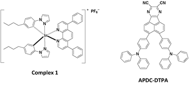
The iTMC complex 1 shown in Fig. 2 was used as the phosphorescent host in this study.27 Complex 1 was synthesized following the procedures detailed in ref. 23. The deep-red TADF compound, 3,4-bis(4-(diphenylamino)phenyl)acenaphtho[1,2-b]pyrazine-8,9-dicarbonitrile (APDC-DTPA) (Fig. 2), was employed as the fluorescent guest.68APDC-DTPA was purchased from Luminescence Technology and was used as received. The neat host film, host–guest films, and guest-dispersed poly(methyl methacrylate) (PMMA) films for photoluminescence (PL) and photophysical studies were spin-coated onto quartz substrates using acetonitrile/dichloromethane (2![[thin space (1/6-em)]](https://www.rsc.org/images/entities/char_2009.gif) :
:![[thin space (1/6-em)]](https://www.rsc.org/images/entities/char_2009.gif) 3, volume ratio) mixed solvents. PMMA was used as an inert matrix for dispersing guest molecules in measuring UV-visible absorption and PL spectra. Since in LECs, the ionic liquid, 1-butyl-3-methylimidazolium hexafluorophosphate [BMIM+(PF6)−] (20 wt%), was added to shorten the device response time, the host–guest films containing the same components as the emissive layer of LECs were employed in PL and photophysical measurements.
3, volume ratio) mixed solvents. PMMA was used as an inert matrix for dispersing guest molecules in measuring UV-visible absorption and PL spectra. Since in LECs, the ionic liquid, 1-butyl-3-methylimidazolium hexafluorophosphate [BMIM+(PF6)−] (20 wt%), was added to shorten the device response time, the host–guest films containing the same components as the emissive layer of LECs were employed in PL and photophysical measurements.
UV-visible absorption spectra were recorded on a spectrophotometer (UV-1800, Shimadzu). PL spectra were measured using a fiber-optic spectrometer (USB2000, Ocean Optics) and the excitation source was a mercury lamp (365 nm). PLQYs of thin films were determined with a calibrated integrating sphere system (FS5, Edinburgh). The excited-state lifetimes of thin films were measured by using the time-correlated single photon counting technique (FS5, Edinburgh). The transient PL signals were detected at suitable wavelengths selected by the monochromator.
Standard cleaning and UV/ozone treatments were performed on the indium tin oxide (ITO) coated glass substrates before thin film deposition. Then the substrates were spin-coated with poly(3,4-ethylenedioxythiophene):poly(styrene sulfonate) (PEDOT:PSS) layers (40 nm) at 4000 rpm and they were baked at 150 °C for 30 min in ambient air. The emissive layers of the host–guest LECs contained complex 1 (80 − x wt%), APDC-DTPA (x wt%) and ionic liquid [BMIM+(PF6)−] (20 wt%), where x = 3, 2, 1, 0.5, and 0.25. The emissive layers were spin-coated on the PEDOT:PSS layers from the mixture of the host, guest, and ionic liquid in acetonitrile/dichloromethane (2![[thin space (1/6-em)]](https://www.rsc.org/images/entities/char_2009.gif) :
:![[thin space (1/6-em)]](https://www.rsc.org/images/entities/char_2009.gif) 3, volume ratio) mixed solutions (60 mg mL−1) at 3000 rpm in ambient air. After spin coating of emissive layers, the samples were then baked at 70 °C for 10 hours in a nitrogen glove box. Finally, a silver top contact was deposited by thermal evaporation in a vacuum chamber (ca. 10−6 torr). The thicknesses of the emissive layers were measured to be ca. 180 nm by ellipsometry. The electrical and emission characteristics of LEC devices were measured using source-measurement units (B2901A, Keysight) and a calibrated Si photodiode. The EL spectra of the LEC devices were recorded using a calibrated fiber-optic spectrometer (USB2000, Ocean Optics). Measuring the PL and the EL spectra with the same system facilitated spectral comparison. All LEC device measurements were done at constant bias voltages (2.2, 2.3, 2.4, and 2.5 V). Device measurements were performed in a glove box filled with nitrogen to reduce the device degradation rate.
3, volume ratio) mixed solutions (60 mg mL−1) at 3000 rpm in ambient air. After spin coating of emissive layers, the samples were then baked at 70 °C for 10 hours in a nitrogen glove box. Finally, a silver top contact was deposited by thermal evaporation in a vacuum chamber (ca. 10−6 torr). The thicknesses of the emissive layers were measured to be ca. 180 nm by ellipsometry. The electrical and emission characteristics of LEC devices were measured using source-measurement units (B2901A, Keysight) and a calibrated Si photodiode. The EL spectra of the LEC devices were recorded using a calibrated fiber-optic spectrometer (USB2000, Ocean Optics). Measuring the PL and the EL spectra with the same system facilitated spectral comparison. All LEC device measurements were done at constant bias voltages (2.2, 2.3, 2.4, and 2.5 V). Device measurements were performed in a glove box filled with nitrogen to reduce the device degradation rate.
Results and discussion
PL and photophysical studies of phosphor-sensitized TADF
The chemical structures of the host and guest materials used in this study are shown in Fig. 2. The previously reported complex 1 was used as the phosphorescent host.27 The host neat film shows yellow PL emission centered at 573 nm (Fig. 3). When considering the neat-film PLQY of complex 1 (61%) and the peak EQE of the LEC based on complex 1 (13.6%), complex 1 exhibits good carrier balance and thus it is suitable to serve as the host material for the LECs based on phosphor-sensitized TADF.27 Meanwhile, the efficient deep-red TADF emitter, APDC-DTPA, was used as the fluorescent guest.68 The guest shows an intense absorption band near the host emission band (Fig. 3) and efficient host–guest energy transfer can be expected as a consequence. The guest dispersed in the inert PMMA matrix (1 wt%) shows a PL emission peak at 657 nm and a large portion of PL emission extends into the NIR spectral region. Since PMMA is a non-polar medium, the PL properties of the guest APDC-DTPA in polar host complex 1 should be further clarified.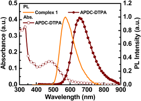 | ||
| Fig. 3 Absorption and PL spectra of APDC-DTPA in a PMMA film (1 wt%) and PL spectrum of a neat film of complex 1. | ||
The PL spectra of the host–guest films based on complex 1 doped with APDC-DTPA (3, 2, 1, 0.5, 0.25, and 0 wt%) and [BMIM+(PF6)−] (20 wt%) are depicted in Fig. 4. The PL peak wavelengths and the PLQYs of these host–guest films are summarized in Table 1. As the guest doping concentration increases, the residual host emission reduces and the PLQY decreases as well. A higher guest doping concentration enhances the host–guest energy transfer rate such that the guest emission dominates total PL emission and the PLQY of the host–guest film approaches that of the guest dispersed in a host film. Since complex 1 exhibits a higher PLQY than APDC-DTPA, the host–guest film shows a decreasing PLQY with increasing guest doping concentration (Table 1). In addition, the PL spectrum of APDC-DTPA dispersed in polar complex 1 shows a slight bathochromic shift in comparison with that in non-polar PMMA (cf. 1 wt% PL spectra in Fig. 3 and 4). Since the donor–acceptor (D–A) type APDC-DTPA exhibits significant intramolecular charge-transfer nature, the bathochromic shift in the PL spectrum when doped in polar complex 1 may be due to the strong interactions between highly polarized excited-state chromophores and the surrounding polar molecules.63 A previous work reported a similar solid-state solvation effect for APDC-DTPA doped in the host molecule with a higher dipole moment.69 Such a bathochromic shift in the guest emission in polar medium is beneficial for harvesting a higher percentage of NIR emission from the EL output of the host–guest LECs based on complex 1 doped with APDC-DTPA.
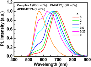 | ||
| Fig. 4 PL spectra of the host–guest films based on complex 1 doped with APDC-DTPA (3, 2, 1, 0.5, 0.25, and 0 wt%) and [BMIM+(PF6)−] (20 wt%). | ||
| APDC-DTPA [wt%] | PL max [nm] | Φ PL,H-G [%] | η PL,H , η PL,G [%] | η ET [%] | Φ PL,G [%] | τ H [ns] | τ G [ns] |
|---|---|---|---|---|---|---|---|
| a PL peak wavelength. b Absolute PLQY of the host–guest film measured by using an integrating sphere. c Percentages of the host and the guest PL emissions for the host–guest film. d Host–guest energy transfer efficiency. e PLQY of the guest doped in the host–guest film. f Excited-state lifetimes and weightings obtained by the biexponential fit at the host emission band (ca. 550–570 nm). g Excited-state lifetimes and weightings obtained by the biexponential fit at the guest emission band (ca. 680–720 nm). | |||||||
| 3 | 691 | 26.7 | (3, 97) | 98.9 | 26.2 | 14 (56%), 63 (44%) | 15 (84%), 74 (16%) |
| 2 | 682 | 30.6 | (5, 95) | 98.0 | 29.7 | 24 (48%), 115 (52%) | 19 (67%), 94 (33%) |
| 1 | 671 | 33.7 | (13, 87) | 94.2 | 31.1 | 39 (41%), 179 (59%) | 23 (60%), 131 (40%) |
| 0.5 | 662 | 37.2 | (26, 74) | 87.2 | 31.6 | 59 (29%), 271 (71%) | 29 (46%), 216 (54%) |
| 0.25 | 628 | 40.7 | (40, 60) | 78.5 | 31.1 | 89 (22%), 400 (78%) | 36 (34%), 306 (66%) |
| 0 | 573 | 75.7 | (100, 0) | — | — | 346 (27%), 855 (73%) | — |
Concentration quenching of the guest molecules is a possible bottleneck to limit the device efficiency of the host–guest LECs. To examine the PLQYs of the doped guest in thin films of complex 1, the host and the guest emissions should be separately considered. The PL spectra of the host–guest films can be fitted by adjusting the contribution percentages of the host and the guest emissions (Fig. S1, ESI†). The estimated percentages of host and guest emissions (ηPL,H and ηPL,G) for the host–guest films based on complex 1 doped with 3, 2, 1, 0.5, and 0.25 wt% APDC-DTPA are (3% and 97%), (5% and 95%), (13% and 87%), (26% and 74%), and (40% and 60%), respectively. The energy transfer efficiency (ηET), which is the percentage of energy transferred from the host to the guest, can be correlated with the individual PLQYs contributed from the host and the guest in the following eqn (1) and (2).
| ΦPL,H–G × ηPL,H = (1−ηET) × ΦPL,H | (1) |
| ΦPL,H–G × ηPL,G = ηET × ΦPL,G | (2) |
In both equations, ΦPL,H–G is the PLQY of the host–guest film, ηPL,H and ηPL,G are the percentages of the host and the guest emissions, respectively, and ΦPL,H and ΦPL,G are the individual PLQYs in the host–guest film for the host and the guest, respectively. If ΦPL,H is estimated to be almost the same (75.7%, Table 1) for low guest doping concentrations (0–3 wt%), ηET for these samples can be obtained by employing eqn (1) with related parameters. The ηET values of the host–guest films based on complex 1 doped with 3, 2, 1, 0.5, and 0.25 wt% APDC-DTPA are 98.9, 98.0, 94.2, 87.2, and 78.5%, respectively. By using eqn (2) with the obtained ηET values and other related parameters, ΦPL,G at doping concentrations of 3, 2, 1, 0.5, and 0.25 wt% can be derived to be 26.2, 29.7, 31.1, 31.6, and 31.1%, respectively. This reveals that the concentration quenching effect is not severe for 0.25–3 wt% APDC-DTPA doped in thin films of complex 1. All the parameters related to the host–guest energy transfer in the host–guest films are summarized in Table 1 for comparison.
To further study the photophysics of the proposed phosphor-sensitized TADF system, the transient PL decay curves of the host and the guest emission bands of the host–guest films were measured (Fig. S2–S7, ESI†). Excited-state lifetimes and weightings obtained by the biexponential fit of the transient PL decay curves for both emission bands are summarized in Table 1. Compared with the host-only film, the host–guest energy transfer is responsible for the faster decay rate of the host emission band of the host–guest films, especially at higher guest doping concentrations. The faster decay component of the guest emission band is the prompt fluorescence decay of the guest molecules, which comes from the Förster energy transfer from the host triplet state to the guest singlet state. Since the singlet excitons on the phosphorescent host can be converted to the emissive triplet excitons via the rapid ISC process, efficient host–guest Förster energy transfer ensures harvesting both the singlet and triplet excitons on the host molecules. The slower decay component of the guest emission band is the delayed fluorescence decay of the guest molecules, which is absent in the phosphor-sensitized fluorescent system.63 This results from the Dexter energy transfer from the host triplet state to the guest triplet state, followed by effective RISC to the guest singlet state due to a small single–triplet splitting (ΔEST) of 0.14 eV for APDC-DTPA.68 Both the guest prompt and delayed fluorescence decays are slower when the guest doping concentration is lower since the Förster and the Dexter energy transfer rates slow down. However, in comparison with the guest prompt fluorescence decay, the guest delayed fluorescence decay retards more significantly with decreasing guest doping concentration since the Dexter energy transfer (exponential distance dependence) is more sensitive to the host–guest intermolecular distance than the Förster energy transfer (R−6 distance dependence). The photophysical data clarify the host–guest energy transfer processes in the proposed phosphor-sensitized TADF system and confirm the guest delayed fluorescence decay through the effective RISC channel from the guest triplet state, which can ensure recycling of the guest triplet excitons generated by the Dexter energy transfer from the host triplet state and direct triplet exciton formation on the guest molecules under electrical excitation.
EL characteristics of deep-red phosphor-sensitized TADF LECs
Before fabricating the host–guest LECs, the surface morphology of the thin film of complex 1 doped with 20 wt% [BMIM+(PF6)−] and 0.25 wt% APDC-DTPA was examined by atomic force microscopy (AFM). 3D and 2D AFM surface images of the host–guest films are shown in Fig. 5(a) and (b), respectively. The thin film surface is rather smooth and the root mean square roughness (Rq) is 0.233 nm. This confirms no sign of phase separation in the thin film and thus guarantees good device fabrication yield.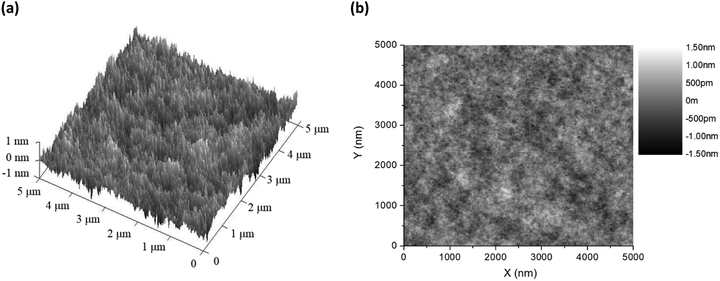 | ||
| Fig. 5 (a) 3D and (b) 2D AFM surface images of the thin films of complex 1 doped with 20 wt% [BMIM+(PF6)−] and 0.25 wt% APDC-DTPA. | ||
Deep-red LECs based on complex 1 doped with APDC-DTPA were fabricated and tested to confirm the advantages of phosphor-sensitized TADF. The EL characteristics of these LECs are summarized in Table 2. The EL spectra of all LECs are almost unchanged with time under constant-bias operation (Fig. S8, ESI†). The voltage-dependent EL spectra of the deep-red LECs based on complex 1 doped with APDC-DTPA at 3, 2, 1, 0.5, and 0.25 wt% are depicted in Fig. 6(a)–(e), respectively. Different from the PL spectra, the EL spectra contain predominantly guest emission along with almost untraceable host emission. Under electrical excitation, direct exciton formation on the lower-gap guest molecules is more likely to occur than photoexcitation, consequently resulting in more pronounced guest EL emission. Compared with the PL spectra, the EL spectra show a slight bathochromic shift in the emission peak wavelengths (cf.Tables 1 and 2), which may be attributed to the spectral modification by the microcavity effect of the device optical structure.7,8 A higher guest doping concentration leads to a slightly longer EL emission peak wavelength, which implies more guest emission, due to more complete host–guest energy transfer. In addition, carrier trapping and direct exciton formation on the guest with a lower energy gap are more preferred under a lower bias voltage. Therefore, a bathochromic shift in the EL spectra can be observed when the bias voltage decreases, especially for the host–guest LEC with a higher guest doping concentration. These EL spectra confirm that deep-red emission can be obtained from the proposed phosphor-sensitized TADF LECs.
| APDC-DTPA [wt%] | Bias [V] |
λ
max,![[thin space (1/6-em)]](https://www.rsc.org/images/entities/char_2009.gif) EL
[nm] EL
[nm] |
L max [μW cm−2] |
η
ext,![[thin space (1/6-em)]](https://www.rsc.org/images/entities/char_2009.gif) max
[%] max
[%] |
η
P,![[thin space (1/6-em)]](https://www.rsc.org/images/entities/char_2009.gif) max
[mW W−1] max
[mW W−1] |
|---|---|---|---|---|---|
| a EL peak wavelength. b Maximal light output power. c Maximal external quantum efficiency. d Maximal power efficiency. | |||||
| 3 | 2.5 | 686 | 5.08 | 0.61 | 4.48 |
| 2.4 | 690 | 2.85 | 1.01 | 7.82 | |
| 2.3 | 698 | 0.61 | 1.46 | 11.78 | |
| 2.2 | 703 | 0.20 | 2.38 | 20.04 | |
| 2 | 2.4 | 682 | 3.12 | 1.31 | 10.12 |
| 2.3 | 684 | 0.79 | 2.31 | 18.59 | |
| 2.2 | 689 | 0.24 | 3.38 | 28.08 | |
| 1 | 2.4 | 675 | 3.74 | 2.33 | 17.99 |
| 2.3 | 687 | 1.09 | 2.92 | 23.48 | |
| 2.2 | 684 | 0.28 | 3.72 | 31.27 | |
| 0.5 | 2.2 | 684 | 0.32 | 4.76 | 40.06 |
| 0.25 | 2.2 | 682 | 0.31 | 5.11 | 43.00 |
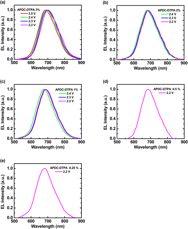 | ||
| Fig. 6 Voltage-dependent EL spectra of the phosphor-sensitized deep-red TADF LECs based on complex 1 doped with [BMIM+(PF6)−] (20 wt%) and APDC-DTPA at (a) 3, (b) 2, (c) 1, (d) 0.5, and (e) 0.25 wt%. | ||
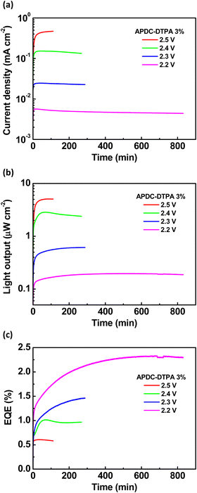
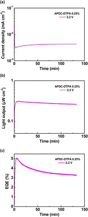
To further evaluate the device performance, the time-dependent current density, light output, and EQE of the deep-red LECs based on complex 1 doped with APDC-DTPA (3 wt%) are shown in Fig. 7(a)–(c), respectively. After a bias was applied, the mobile ions in the LECs were driven to drift toward the electrodes, resulting in gradually formed electrochemically doped layers. These doped layers facilitated carrier injection; thus, the device current increased with time. When the doped layers were formed completely, the carrier injection rate approached a steady state, and the device current reached a maximal value. Higher bias voltages lead to higher maximal device currents due to higher electric fields inside the devices (Fig. 7(a)). The light output generally followed the temporal evolution of the device current (Fig. 7(b)). The EQE rapidly increased after a bias was applied because the carrier balance was improved significantly through the formation of the doped layers. It approached the maximal value when the doped layers were well formed (Fig. 7(c)). Apparently, the device efficiency decreases as the bias voltage increases. The density of the guest triplet excitons, which exhibit longer excited-state lifetimes, increases significantly at a higher device current driven by a higher bias voltage. As such, the triplet–triplet annihilation pathway strongly competes with the RISC process, rendering reduced device efficiency. In addition to the device with 3 wt% APDC-DTPA, the temporal EL properties of the deep-red LECs based on complex 1 doped with 2, 1, 0.5, and 0.25 wt% APDC-DTPA are shown in Fig. S9–S11 (ESI†) and Fig. 8, respectively. All devices show a similar temporal evolution trend in current density, light output, and EQE. However, the device efficiency significantly increases as the guest doping concentration decreases. This would be attributed to the reduced possibilities of the host–guest Dexter energy transfer and the direct triplet exciton formation on the guest, followed by subsequent triplet–triplet annihilation at a lower guest doping concentration. At the lowest APDC-DTPA doping concentration of 0.25 wt%, the peak EQE of the deep-red LECs reached 5.11% (Fig. 8(c)). Such a device efficiency is among the highest reported values for deep-red LECs and successfully confirms that the proposed phosphor-sensitized TADF LECs can generate efficient deep-red EL emission.
To further explore the EL characteristics of the deep-red LECs based on complex 1 doped with APDC-DTPA, the time-dependent current density, light output, and EQE of the LECs based on complex 1 were measured and are shown in Fig. S12(a)–(c) (ESI†), respectively. The temporal evolution of current density and light output for the host–guest LECs and the host-only LECs is similar (cf. Fig. 7(a), (b), 8(a), (b) and Fig. S9(a), (b), S10(a), (b), S11(a), (b), S12(a), (b), ESI†). This reveals that the electrochemical stability of complex 1 dominates the device stability of the host–guest LECs. It is noted that the EQE of the host–guest LECs doped with 0.25 wt% APDC-DTPA at 2.2 V reaches the maximum value rapidly and then decreases with time (Fig. 8(c)). However, the EQE of the host–guest LECs doped with higher APDC-DTPA concentrations at 2.2 V increases with time to approach the maximum value (Fig. 7(c) and Fig. S9(c), S10(c), S11(c), ESI†). This may be attributed to the slightly different time-dependent current densities for the host–guest LECs doped with 0.25 wt% and higher APDC-DTPA concentrations at 2.2 V. For the host–guest LECs doped with >0.25 wt% APDC-DTPA at 2.2 V, the device currents slightly decrease with time such that the effect of triplet–triplet annihilation is mitigated. Therefore, their time-dependent EQEs increase with time, resembling that of the host-only LEC at 2.2 V (Fig. S12(c), ESI†). On the other hand, the EQE of the host–guest LEC doped with 0.25 wt% APDC-DTPA at 2.2 V reaches the peak value at the minimum current density. After that, the EQE decreases with time since the triplet–triplet annihilation is enhanced by the increasing current. These results reveal that low current density is critical for the phosphor-sensitized TADF LEC to achieve the best device efficiency.
To check the emissive exciton generation efficiency of the proposed phosphor-sensitized TADF LECs, i.e., the percentage of the emissive excitons generated on the guest, analysis of the device efficiency by evaluating the related device factors is performed. The device EQE can be determined by the parameters shown in the following eqn (3).
| ηEQE = ηout × γ × ηS,T × ηQY | (3) |
In eqn (3), ηEQE is the measured EQE of the LEC, ηout is the light outcoupling efficiency, γ is the factor of carrier balance, ηS,T is the emissive exciton generation efficiency of the guest and ηQY is the guest PLQY when dispersed in a host film. Detailed analysis of these parameters for the host-only LEC has been carried out in ref. 23. In this work, low-concentration guest molecules (0.25–3 wt%) are doped in the host LECs with a similar device thickness. The device current does not show a clear decreasing trend as the guest doping concentration increases; the differences in currents between different devices come from the run-to-run variation and are within the experimental errors (cf.Fig. 7(a), 8(a) and Fig. S9(a), S10(a), S11(a), ESI†). This reveals that the carrier trapping, which alters the emission zone position, in the proposed host–guest LECs is insignificant. Therefore, the light outcoupling efficiency and the carrier balance of the host–guest LECs would not change significantly from those of the host-only LECs. For these reasons, ηout (27.8%) and γ (80.7%) of the host-only LECs adopted from ref. 23 are employed in this analysis. The guest PLQYs when dispersed in host films (ηQY) have been estimated in the previous section and are summarized in Table 1. By applying the related parameters in eqn (3), the maximal ηS,T, i.e., employing the maximal EQE at 2.2 V, of the deep-red LECs based on complex 1 doped with APDC-DTPA of 3, 2, 1, 0.5, and 0.25 wt% can be determined to be 40.5, 50.8, 53.2, 67.2, and 73.2%, respectively. With similar PLQYs of the guest (0.25–3 wt% doping), increasing device efficiency with decreasing guest doping concentration reflects that a higher percentage of emissive excitons can be harvested. At the lowest guest doping concentration (0.25 wt%), higher than 70% of the excitons on the guest molecules can be used for light emission, approaching 3× EL efficiency of the fluorescent devices (ηS,T = 25%). This value is also much higher than that (ηS,T ∼ 55%) obtained from the previously reported phosphor-sensitized fluorescent LECs.63 This clearly confirms the effectiveness of the RISC process to recycle the triplet excitons on the guest molecules in the phosphor-sensitized TADF LECs. However, when the guest doping concentration or device current increases, the density of long-lifetime triplet excitons on the guest, which come from the host–guest Dexter energy transfer and the direct triplet exciton formation on the guest due to carrier trapping (Fig. 1), increases significantly. It turns out that the enhanced triplet–triplet annihilation rate reduces the number of triplet excitons taking the RISC pathway to singlet states for harvesting, lowering the device efficiency consequently. Since the carrier trapping and subsequent direct exciton formation on the guest play a relatively minor role in reducing the device efficiency, the Dexter energy transfer may have a more significant impact on the device performance of the proposed host–guest LECs. The analysis reveals that the proposed phosphor-sensitized TADF LEC with a lower guest doping concentration can offer efficient deep-red EL efficiency at a lower device current. Nevertheless, triplet–triplet annihilation on the guest molecules remains the bottleneck for improving the device efficiency when the guest doping concentration or the device current increases.
Conclusions
In summary, we have demonstrated highly efficient phosphor-sensitized TADF LECs based on a phosphorescent complex 1 as the host and a deep-red TADF emitter APDC-DTPA as the guest. PL and photophysical studies reveal the efficient host–guest Förster energy transfer, which ensures harvesting both singlet and triplet excitons on the host molecules. Furthermore, the host–guest Dexter energy transfer followed by the effective RISC process, which recycles the guest triplet excitons, can also be identified by the guest delayed fluorescence decay. The host–guest LECs with 0.25 wt% APDC-DTPA achieve a peak EQE of up to 5.11%, which is among the highest reported for deep-red LECs. Further analysis of this device efficiency by evaluating related device parameters shows that more than 73% of the excitons on the guest molecules can be used for light emission. The effective RISC process to recycle the guest triplet excitons is responsible for such a high percentage of emissive excitons. However, triplet–triplet annihilation on the guest molecules still limits the device efficiency of the phosphor-sensitized TADF LECs when the guest doping concentration or device current is higher.Conflicts of interest
There are no conflicts to declare.Acknowledgements
The authors are grateful for the financial support from the Ministry of Science and Technology of Taiwan, under the grant number MOST 110-2113-M-126-004 and MOST 110-2221-E-A49-090.References
- Q. Pei, G. Yu, C. Zhang, Y. Yang and A. J. Heeger, Science, 1995, 269, 1086 CrossRef CAS PubMed
.
- A. Sandström and L. Edman, Energy Technol., 2015, 3, 329 CrossRef
.
- Z. Zhang, K. Guo, Y. Li, X. Li, G. Guan, H. Li, Y. Luo, F. Zhao, Q. Zhang, B. Wei, Q. Pei and H. Peng, Nat. Photonics, 2015, 9, 233 CrossRef CAS
.
- A. Asadpoordarvish, A. Sandström, C. Larsen, R. Bollström, M. Toivakka, R. Österbacka and L. Edman, Adv. Funct. Mater., 2015, 25, 3238 CrossRef CAS
.
- G.-R. Lin, H.-F. Chen, H.-C. Shih, J.-H. Hsu, Y. Chang, C.-H. Chiu, C.-Y. Cheng, Y.-S. Yeh, H.-C. Su and K.-T. Wong, Phys. Chem. Chem. Phys., 2015, 17, 6956 RSC
.
- J.-H. Hsu and H.-C. Su, Phys. Chem. Chem. Phys., 2016, 18, 5034 RSC
.
- H.-C. Su, ChemPlusChem, 2018, 83, 197 CrossRef CAS PubMed
.
- Z.-P. Yang and H.-C. Su, Adv. Funct. Mater., 2020, 30, 1906788 CrossRef CAS
.
- S. Tang and L. Edman, Top. Curr. Chem., 2016, 374, 40 CrossRef PubMed
.
- K. Youssef, Y. Li, S. O’Keeffe, L. Li and Q. Pei, Adv. Funct. Mater., 2020, 30, 1909102 CrossRef CAS
.
- J.-K. Lee, D. S. Yoo, E. S. Handy and M. F. Rubner, Appl. Phys. Lett., 1996, 69, 1686 CrossRef CAS
.
- R. D. Costa, E. Ortí, H. J. Bolink, F. Monti, G. Accorsi and N. Armaroli, Angew. Chem., Int. Ed., 2012, 51, 8178 CrossRef CAS PubMed
.
- E. Fresta and R. D. Costa, J. Mater. Chem. C, 2017, 5, 5643 RSC
.
- C. Zhang, R. Liu, D. Zhang and L. Duan, Adv. Funct. Mater., 2020, 30, 1907156 CrossRef CAS
.
- Z. B. Hill, D. B. Rodovsky, J. M. Leger and G. P. Bartholomew, Chem. Commun., 2008, 6594 RSC
.
- S. Kanagaraj, A. Puthanveedu and Y. Choe, Adv. Funct. Mater., 2020, 30, 1907126 CrossRef CAS
.
- A. J. N. Bader, A. A. Ilkevich, I. V. Kosilkin and J. M. Leger, Nano Lett., 2011, 11, 461 CrossRef PubMed
.
- E. Nannen, J. Frohleiks and S. Gellner, Adv. Funct. Mater., 2020, 30, 1907349 CrossRef CAS
.
- K. Matsuki, J. Pu and T. Takenobu, Adv. Funct. Mater., 2020, 30, 1908641 CrossRef CAS
.
- M. F. Aygüler, M. D. Weber, B. M. D. Puscher, D. D. Medina, P. Docampo and R. D. Costa, J. Phys. Chem. C, 2015, 119, 12047 CrossRef
.
- Q. S. Zhang, Q. G. Zhou, Y. X. Cheng, L. X. Wang, D. G. Ma, X. B. Jing and F. S. Wang, Adv. Funct. Mater., 2006, 16, 1203 CrossRef CAS
.
- H. J. Bolink, E. Coronado, R. D. Costa, N. Lardiés and E. Ortí, Inorg. Chem., 2008, 47, 9149 CrossRef CAS PubMed
.
- C.-Y. Cheng, C.-W. Wang, J.-R. Cheng, H.-F. Chen, Y.-S. Yeh, H.-C. Su, C.-H. Chang and K.-T. Wong, J. Mater. Chem. C, 2015, 3, 5665 RSC
.
- G.-R. Lin, J.-R. Cheng, C.-W. Wang, M. Sarma, H.-F. Chen, H.-C. Su, C.-H. Chang and K.-T. Wong, J. Mater. Chem. C, 2015, 3, 12492 RSC
.
- S. Tang, A. Sandström, P. Lundberg, T. Lanz, C. Larsen, S. Reenen, M. Kemerink and L. Edman, Nat. Commun., 2017, 8, 1190 CrossRef PubMed
.
- Y.-Z. Chen, D. Luo, C.-H. Hsiang, R.-H. Yi, C.-H. Lin, C.-W. Lu, S.-W. Liu, C.-H. Chang and H.-C. Su, Org. Electron., 2020, 77, 105515 CrossRef CAS
.
- R.-H. Yi, C.-L. Lo, D. Luo, C.-H. Lin, S.-W. Weng, C.-W. Lu, S.-W. Liu, C.-H. Chang and H.-C. Su, ACS Appl. Mater. Interfaces, 2020, 12, 14254 CrossRef CAS PubMed
.
- H.-C. Su, Y.-R. Chen and K.-T. Wong, Adv. Funct. Mater., 2020, 30, 1906898 CrossRef CAS
.
- C.-C. Ho, H.-F. Chen, Y.-C. Ho, C.-T. Liao, H.-C. Su and K.-T. Wong, Phys. Chem. Chem. Phys., 2011, 13, 17729 RSC
.
- C.-L. Lee, C.-Y. Cheng and H.-C. Su, Org. Electron., 2014, 15, 711 CrossRef CAS
.
- A. Pertegás, D. Tordera, J. J. Serrano-Pérez, E. Ortí and H. J. Bolink, J. Am. Chem. Soc., 2013, 135, 18008 CrossRef PubMed
.
- M. Mone, S. Tang, P. Murto, B. A. Abdulahi, C. Larsen, J. Wang, W. Mammo, L. Edman and E. Wang, Chem. Mater., 2019, 31, 9721 CrossRef CAS
.
- M. Rémond, J. Hwang, J. Kim, S. Kim, D. Kim, C. Bucher, Y. Bretonnière, C. Andraud and E. Kim, Adv. Funct. Mater., 2020, 30, 2004831 CrossRef
.
- E. Fresta, A. Charisiadis, L. M. Cavinato, N. Palandjian, K. Karikis, V. Nikolaou, G. Charalambidis, A. G. Coutsolelos and R. D. Costa, Adv. Photonics Res., 2021, 2, 2000188 CrossRef
.
- J. C. John, K. Shanmugasundaram, G. Gopakumar and Y. Choe, ACS Photonics, 2022, 9, 203 CrossRef CAS
.
- S. Wang, X. Li, S. Xun, X. Wan and Z. Y. Wang, Macromolecules, 2006, 39, 7502 CrossRef CAS
.
- S. Tang, P. Murto, X. Xu, C. Larsen, E. Wang and L. Edman, Chem. Mater., 2017, 29, 7750 CrossRef CAS
.
- P. Murto, S. Tang, C. Larsen, X. Xu, A. Sandström, J. Pietarinen, B. Bagemihl, B. A. Abdulahi, W. Mammo, M. R. Andersson, E. Wang and L. Edman, ACS Appl. Energy Mater., 2018, 1, 1753 CrossRef CAS
.
- W. Xiong, S. Tang, P. Murto, W. Zhu, L. Edman and E. Wang, Adv. Opt. Mater., 2019, 7, 1900280 CrossRef
.
- S. Tang, P. Murto, J. Wang, C. Larsen, M. R. Andersson, E. Wang and L. Edman, Adv. Opt. Mater., 2019, 7, 1900451 CrossRef
.
- A. R. Hosseini, C. Y. Koh, J. D. Slinker, S. Flores-Torres, H. D. Abruña and G. G. Malliaras, Chem. Mater., 2005, 17, 6114 CrossRef CAS
.
- H. J. Bolink, L. Cappelli, E. Coronado and P. Gaviña, Inorg. Chem., 2005, 44, 5966 CrossRef CAS PubMed
.
- S. Xun, J. Zhang, X. Li, D. Ma and Z. Y. Wang, Synth. Met., 2008, 158, 484 CrossRef CAS
.
- H. J. Bolink, E. Coronado, R. D. Costa, P. Gaviña, E. Ortí and S. Tatay, Inorg. Chem., 2009, 48, 3907 CrossRef CAS PubMed
.
- A. Breivogel, M. Park, D. Lee, S. Klassen, A. Kühnle, C. Lee, K. Char and K. Heinze, Eur. J. Inorg. Chem., 2014, 288 CrossRef CAS
.
- B. N. Bideh, C. Roldán-Carmona, H. Shahroosvand and M. K. Nazeeruddin, J. Mater. Chem. C, 2016, 4, 9674 RSC
.
- D. A. Ross, P. A. Scattergood, A. Babaei, A. Pertegas, H. J. Bolink and P. I. Elliott, Dalton Trans., 2016, 45, 7748 RSC
.
- A. K. Pal, D. B. Cordes, A. M. Z. Slawin, C. Momblona, A. Pertegás, E. Ortí, H. J. Bolink and E. Zysman-Colman, RSC Adv., 2017, 7, 31833 RSC
.
- B. N. Bideh and H. Shahroosvand, Sci. Rep., 2017, 7, 15739 CrossRef PubMed
.
- G.-Y. Chen, B.-R. Chang, T.-A. Shih, C.-H. Lin, C.-L. Lo, Y.-Z. Chen, Y.-X. Liu, Y.-R. Li, J.-T. Guo, C.-W. Lu, Z.-P. Yang and H.-C. Su, Chem. – Eur. J., 2019, 25, 5489 CrossRef CAS PubMed
.
- B. N. Bideh and H. Shahroosvand, New J. Chem., 2020, 44, 1881 RSC
.
- H. Shahroosvand, L. Heydari, B. N. Bideh and B. Pashaei, RSC Adv., 2020, 10, 14099 RSC
.
- L.-C. Shiu, B.-R. Chang, M. C.-S. Hsiao, W.-S. Sie, M.-L. Wu, L.-X. Huang, C.-M. Wang, G.-H. Lee, I.-J. Chang, H.-C. Su and K.-B. Shiu, Eur. J. Inorg. Chem., 2020, 3517 CrossRef CAS
.
- Y.-X. Liu, R.-H. Yi, C.-H. Lin, Z.-P. Yang, C.-W. Lu and H.-C. Su, J. Mater. Chem. C, 2020, 8, 14378 RSC
.
- B. N. Bideh, H. Shahroosvand and M. K. Nazeeruddin, Inorg. Chem., 2021, 60, 11915 CrossRef PubMed
.
- B. Pashaei, H. Shahroosvand, M. Moharramnezhad, M. A. Kamyabi, H. Bakhshi, M. Pilkington and M. K. Nazeeruddin, Inorg. Chem., 2021, 60, 17040 CrossRef CAS PubMed
.
- B. N. Bideh and H. Shahroosvand, Dalton Trans., 2022, 51, 3652 RSC
.
- E. Fresta, M. D. Weber, J. Fernandez-Cestau and R. D. Costa, Adv. Opt. Mater., 2019, 7, 1900830 CrossRef CAS
.
- E. Fresta, K. Baumgärtner, J. Cabanillas-Gonzalez, M. Mastalerz and R. D. Costa, Nanoscale Horiz., 2020, 5, 473 RSC
.
- M. Mone, S. Tang, Z. Genene, P. Murto, M. Jevric, X. Zou, J. Ràfols-Ribé, B. A. Abdulahi, J. Wang, W. Mammo, M. R. Andersson, L. Edman and E. Wang, Adv. Opt. Mater., 2021, 9, 2001701 CrossRef CAS
.
- E. Fresta, G. U. Mahoro, L. M. Cavinato, J.-F. Lohier, J.-L. Renaud, S. Gaillard and R. D. Costa, Adv. Opt. Mater., 2022, 10, 2101999 CrossRef CAS
.
- M. A. Baldo, M. E. Thompson and S. R. Forrest, Nature, 2000, 403, 750 CrossRef CAS PubMed
.
- H.-C. Su, Y.-H. Lin, C.-H. Chang, H.-W. Lin, C.-C. Wu, F.-C. Fang, H.-F. Chen and K.-T. Wong, J. Mater. Chem., 2010, 20, 5521 RSC
.
- H.-C. Su, H.-F. Chen, P.-H. Chen, S.-W. Lin, C.-T. Liao and K.-T. Wong, J. Mater. Chem., 2012, 22, 22998 RSC
.
- T. Förster, Discuss. Faraday Soc., 1959, 27, 7 RSC
.
- D. L. Dexter, J. Chem. Phys., 1953, 21, 836 CrossRef CAS
.
- H. Uoyama, K. Goushi, K. Shizu, H. Nomura and C. Adachi, Nature, 2012, 492, 234 CrossRef CAS PubMed
.
- Y. Yuan, Y. Hu, Y.-X. Zhang, J.-D. Lin, Y.-K. Wang, Z.-Q. Jiang, L.-S. Liao and S.-T. Lee, Adv. Funct. Mater., 2017, 27, 1700986 CrossRef
.
- Y. Hu, Y. Yuan, Y.-L. Shi, J.-D. Lin, Z.-Q. Jiang and L.-S. Liao, J. Mater. Chem. C, 2018, 6, 1407 RSC
.
Footnotes |
| † Electronic supplementary information (ESI) available. See DOI: https://doi.org/10.1039/d2tc01727j |
| ‡ Equal contribution. |
| This journal is © The Royal Society of Chemistry 2022 |

