 Open Access Article
One-step electrospinning of carbon nanowebs on metallic textiles for high-capacitance supercapacitor fabrics†
Qiyao
Huang
ab,
Libin
Liu
a,
Dongrui
Wang
a,
Junjun
Liu
c,
Zhifeng
Huang
c and
Zijian
Zheng
*ab
aNanotechnology Center, Institute of Textiles and Clothing, The Hong Kong Polytechnic University, Hong Kong, China. E-mail: tczzheng@polyu.edu.hk; Fax: +852 27731432
bAdvanced Research Centre for Fashion and Textiles, The Hong Kong Polytechnic University, Shenzhen Research Institute, Shenzhen 518000, China
cDepartment of Physics, Hong Kong Baptist University, Kowloon Tong, Kowloon, Hong Kong, China
First published on 18th January 2016
Abstract
We report the development of high-performance wearable supercapacitor fabrics based on flexible metallic fabrics (Ni–cotton), on which nanofiber webs containing multi-walled carbon nanotubes (MWCNTs) are directly electrospun without the need for any post-treatment. The as-prepared fabric devices show a high areal capacitance of 973.5 mF cm−2 (2.5 mA cm−2) and ultrahigh stability in the bending test at a very small bending radius (2 mm). In addition, such supercapacitor fabrics can be integrated into commercial textiles with any desirable forms, indicating the remarkable application potentials in wearable electronics.
Wearable electronics attract remarkable attention both in academia and industry because of their wide applications such as healthy monitoring devices, biomedical implants, portable military equipment, and smart textiles with built-in electronic functions.1–3 All wearable electronic devices require lightweight, wearable and high-performance energy-storage components to provide power. However, conventional power supply components are rigid and bulky, which have encountered significant difficulty in integration for wearable applications.2,3 Regarding the requisitions as stated above, developing fabric-based energy-storage devices is an ideal solution because textile fabrics exhibit intrinsically mechanical flexibility, lightweight and a high surface area for anchoring active materials, and most importantly, the feasibility of device integration into wearable forms. Among the many energy-storage devices, a supercapacitor shows distinctive advantages due to its high power density, fast charge/discharge capability, excellent reversibility, long cycle life and safety, which are very suitable for wearable applications.3–7
To fabricate fabric-based supercapacitors, a typical procedure starts with coating conductive components, followed by introducing active materials and assembling into devices.8,9 In this field, carbon-based materials such as activated carbon,2 graphene10 and carbon nanotubes (CNTs)11,12 are extensively studied to coat on non-conductive textiles such as cotton fabrics, which not only provide electrical conductivity for the fabrics but also function as active electrode materials. However, due to the high resistance of carbon-based materials (normally in the range of tens to thousands of Ω sq−1), these supercapacitor fabrics faced issues in high internal resistance.13,14
Although extra metal films such as copper foil or nickel foam can be introduced as current collectors during the device assembly and performance test to solve this issue, they lead to other problems such as device rigidity and poor fatigue resistance. Alternatively, researchers have recently demonstrated that by using conductive carbon fabrics or carbonized cotton fabrics as current collectors, followed by depositing other active materials, such as carbon nanomaterials,13,15,16 metal oxides,17–19 conducting polymers,20–22 and their hybrids,20,23,24 supercapacitor devices with good flexibility and high capacitances can be successfully achieved at the same time. Nevertheless, these approaches usually involve harsh processing conditions, for example, electrochemical/chemical activation of carbon cloths,5,17 hydrothermal reduction of graphene oxide,16 hydrothermal or vapor deposition of metal oxide18,25,26 and high temperature carbonization (800–1000 °C).19 These techniques are therefore not suitable for scalable production. To date, it is still a significant challenge to fabricate high-performance fabric-based supercapacitors with low-cost materials and high-throughput fabrication methods.27
To address this challenge, we report herein a cost-effective and continuous material approach for making high-performance supercapacitor fabrics. This approach is based on direct electrospinning of multi-walled carbon nanotubes (MWCNTs) onto wearable nickel-coated cotton fabrics (Ni–cotton). Importantly, Ni–cotton is used as the conductive collecting substrate in the electrospinning process, which enables the formation of carbon nanoweb coated metallic fabrics (C-web@Ni–cotton) in one step without the need for any post-treatment. In such an architecture, carbon nanowebs function as the active materials enabling large surface areas of electrochemical double layers, while the metallic textile fabrics act as highly flexible and conductive current collectors as well as mechanical supports for the fragile carbon nanowebs. We demonstrate the use of C-web@Ni–cotton as electrodes for making high-performance wearable supercapacitors, which show remarkable areal capacitance as high as 973.5 mF cm−2 (at 2.5 mA cm−2) and ultrahigh stability in the bending test at a very small bending radius (2 mm). To the best of our knowledge, this is the best performing fabric-based supercapacitor reported to date.
Fig. 1 shows the fabrication process and the layout of the supercapacitor fabrics. The fabrication starts from the preparation of Ni–cotton by using solution-processed polymer-assisted metal deposition (PAMD), which was developed by our research group previously.14,28–30 We have demonstrated that metal-coated textile materials including yarns and fabrics prepared by PAMD exhibited high electrical conductivity while maintaining good flexibility, lightweight and durability, showing great application potentials as electrodes in electronic devices.14,28,31,32 Detailed PAMD procedures can be found in the ESI.† The Ni–cotton fabric was then loaded onto the rotating collector of an electrospinning system, in which Ni–cotton was used directly as the conductive collecting substrate in the electrospinning process. An N,N′-dimethylformamide (DMF) solution containing a mixture of concentrated MWCNTs (60–80 wt%) and polyacrylonitrile (PAN) was electrospun directly onto the rotating Ni–cotton fabric under a bias of 25 kV for a certain length of time to yield the C-web@Ni–cotton electrode. Finally, two pieces of C-web@Ni–cotton electrodes were assembled, together with a piece of pristine cotton fabric as the separator, to form a symmetrical supercapacitor fabric device.
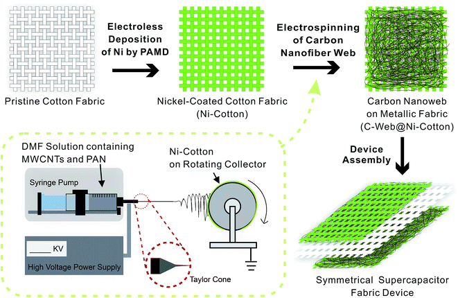 | ||
| Fig. 1 Schematic illustration of the fabrication procedures of supercapacitor fabrics. The inset shows the details of the one-step electrospinning setup. | ||
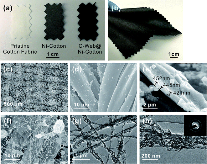
As shown in Fig. 2a and b, the surface of the pristine cotton fabric was coated with a layer of Ni after carrying out the PAMD process, leading to an obvious color change of the fabric from white to dark grey. Because the entire cotton fabric was immersed in the reaction bath during PAMD, Ni was able to be evenly and densely deposited on the surface of the cotton fibers of the fabric (Fig. 2c and d), and the thickness of this Ni coating was estimated to be ∼440 nm (Fig. 2e). The as-made Ni–cotton fabric exhibited very low sheet resistance, being ∼0.2 Ω sq−1. This value is lower than that of the conductive textile fabrics commonly used for fabric-based supercapacitors in the literature, including carbonized cotton fabrics (10–20 Ω sq−1,12,13,19 225–1225 Ω sq−1),13 single-walled carbon nanotube (SWCNT)-coated cotton fabrics (∼2 Ω sq−1)11 and GO-coated cotton fabrics (∼700 Ω sq−1).10 Remarkably, this highly conductive Ni–cotton fabric maintained textile-like flexibility and lightweight (23 mg cm−2). No obvious increase in sheet or bulk resistance was observed after 1000 cycles of the bending test.31
After the electrospinning process, a three-dimensional nanofiber web was formed on the surface of Ni–cotton (Fig. 2a and f). The diameters of the nanofibers are in the range of 100 nm to 400 nm (Fig. 2g). Unlike the smooth pure PAN nanofibers reported in the literature,33,34 the nanofibers fabricated in our experiment are corrugated and have a rough surface. In addition, we found that some large beads were formed, which could be attributed to a small portion of not well-dispersed MWCNTs in the spinning solution and the agglomeration of MWCNTs due to their high proportion. Importantly, we found that oriented and bundled MWCNTs, which were partially embedded in the PAN matrix, were interconnected through the entire nanoweb network (Fig. 2g and h). The interconnection of MWCNTs can be attributed to their high proportion (60 wt% of the solute) in the spinning solution, which is enabled by the use of a metallic fabric as a conductive collection substrate. It should be noted that much lower CNT concentrations (2–26 wt%) are required in conventional electrospinning of CNT-based nanofiber webs, where metallic fabric collecting substrates are not in use.33,35–38 This is because a high CNT concentration results in brittle electrospun webs, which severely affects the mechanical performance during the applications. However, the use of low CNT concentration leads to a discontinuous morphology of the embedded CNTs in the nanofiber webs.35–37,39 As a result, one has to carbonize the nanofibers in a high annealing temperature range of 700–1000 °C to improve the conductivity and expose the CNTs for electrochemical applications such as supercapacitors.35 Such an energy-consuming and toxic-substance-releasing step is particularly undesirable in large scale device fabrication.40 In contrast, we use a highly conductive metallic fabric (Ni–cotton) as the collecting substrate in the electrospinning process to provide mechanical support for the fragile carbon nanoweb electrospun directly from high-concentration MWCNT solutions. This room-temperature and one-step process eliminates the need for post-stabilization and carbonization steps, making the entire electrode fabrication simple, continuous and low-cost.
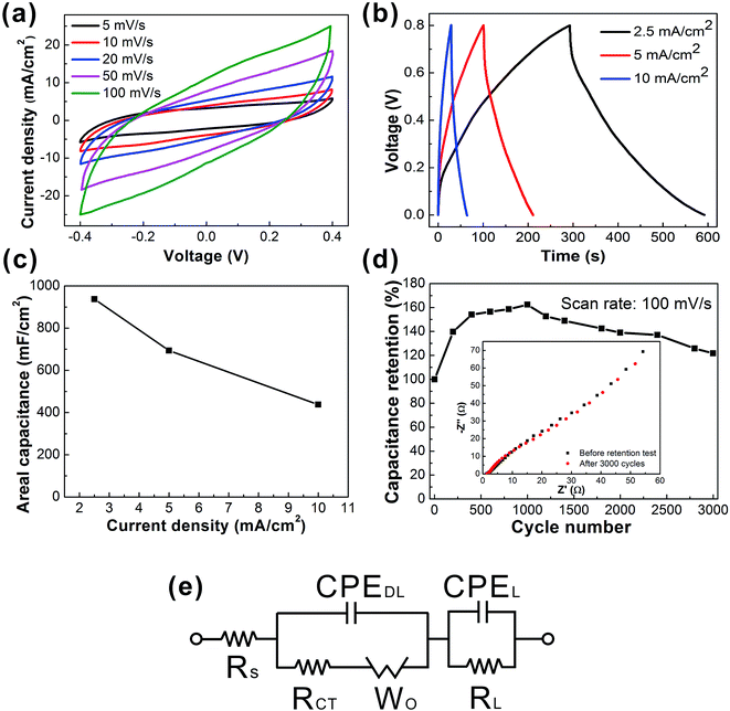
Such a web of interconnected MWCNTs ensures the high electrical conductivity and large exposed surface area of active materials, which lead to remarkable electrochemical capacitance. To investigate the electrochemical performance of the C-web@Ni–cotton fabric electrodes, we assembled the symmetric fabric supercapacitors with a pristine cotton separator, and tested the device in 1 M Na2SO4 liquid electrolyte. It is believed that compared with a three-electrode configuration, the two-electrode test configuration can better provide the true indication of the electrode material's performance.41Fig. 3 shows the electrochemical performance of the fabric device assembled with C-web@Ni–cotton fabric electrodes, which were made with 20 min electrospinning time. Cyclic voltammetry (CV) curves maintained the rectangular-like and symmetric shapes at an increasing scan rate from 5 mV s−1 to 100 mV s−1, indicating an ideal and stable electrochemical behavior (Fig. 3a). In addition, high coulombic efficiency (nearly 100%) and galvanostatic charge/discharge (GCD) curves (Fig. 3b) with symmetrical triangular shapes at different current densities were also recorded. Remarkably, these fabric supercapacitors possess extremely high device capacitance, being 973.5 mF cm−2 at 2.5 mA cm−2, and 437.5 mF cm−2 at 10 mA cm−2 (Fig. 4d), which is six fold higher than that of supercapacitors made with CNT-embedded and carbonized carbon nanofibers (144 mF cm−2 at 2.5 mA cm−2)37,42 and also better than other state-of-the-art carbon-based and metal oxide-based fabric supercapacitors reported in the literature (Table S1†), including SWCNTs@cotton fabric (480 mF cm−2 at 0.2 mA cm−2),1 activated carbon@cotton fabric (435 mF cm−2 at 5 mA cm−2),2 MnO2/TiN@carbon cloth//activated carbon cloth (215.2 mF cm−2 at 6 mA cm−2),17 and Ppy/MO@cotton fabric (309 mF cm−2 at 0.6 mA cm−2).21
With longer electrospinning time, denser and thicker carbon nanowebs were formed on the Ni–cotton fabrics, and vice versa. Fig. S2b† summarizes the areal capacitances of the fabric supercapacitors with different electrospinning times from 5 min to 2 h. The areal capacitance of the fabric device first increased when the electrospinning time extended from 5 to 20 min, because lower loading of carbon nanofibers caused smaller capacitances. However, the device capacitance also decreased when further increasing the electrospinning from 20 min to 2 h. For example, the areal capacitance of the device with 2 h electrospinning time dropped to 144.6 mF cm−2. This is because the over-dense nanofiber web hinders the ion diffusion between the electrolyte and electrode, resulting in the smaller capacitance (Fig. S2i–n†). We also investigated the impact of the MWCNT concentration on the electrochemical performance. The areal capacitances of the fabric supercapacitors increased with the MWCNT concentration from 20% to 60% (Fig. S3a and b†). Increasing the concentration of MWCNTs results in higher loading and sufficient interconnection of MWCNTs within the nanoweb network, which therefore could cause the higher area capacitance (Fig. S3c–e†). We also found that further increasing the concentration of MWCNTs (from 60 wt% to 80 wt%) resulted in decreasing the electrochemical capacitance (Fig. S3a and b†). The reason is because with ultrahigh MWCNT concentration, a large number of beads are formed, which leads to the decrease in the surface area and electrical conductivity of the electrode (Fig. S3f and g†).
More importantly, the fabric device showed excellent cycling stability without any capacitance decay after 3000 cycles (Fig. 3d). The device capacitance increased in the first 1000 cycles and then gradually decreased. Electrochemical impedance spectroscopy (EIS) measurements were conducted to further characterize the fabric device performance. And we also configured an equivalent circuit comprising a set of resistors and capacitors in series and parallel to fit the EIS plots (Fig. 3e). The as-fitted plots are shown in the ESI (Fig. S3†).43–45 From the EIS plots, straight lines with 45° slope were observed for both samples (supercapacitor before and after the retention test) in the low frequency region, indicating the stable and fast ion diffusion capability of the device during the cycling test. The equivalent series resistance (ESR) Rs, which is used to describe the resistance of the electrolyte combined with the internal resistance of the electrode, is only approximately 1.28 Ω. Such low ESR values indicate the low internal resistance and excellent electrochemical cycling stability of the fabric device.44,46 The charge transfer resistance (Rct) of the sample after 3000 cycles also slightly decreased from 0.77 Ω to 0.71 Ω, which was associated with the fast ion transport within the supercapacitor because of the increased contact area at the electrode–electrolyte interface. SEM images also showed no obvious morphological change of the carbon nanowebs and the Ni–cotton fabric after the 3000 cycle retention test (Fig. S4a and b†). These results confirm the stable ionic and electrical conductivity of the C-web@Ni–cotton fabric electrodes. The chemical compositions of the samples were further examined by X-ray photoelectron spectroscopy (XPS) measurements. After the retention test, multiple strong peaks from 855 to 880 eV appeared, which indicates the formation of a mixture of nickel oxides and hydroxides (Fig. S4c and d†).47–49 Since nickel oxides/hydroxides have been well known as good pseudocapacitive electrode materials,8,50 we deduce that the capacitive increase in the first 1000 cycles may be attributed to the partial oxidation of surface Ni, with better surface wetting.
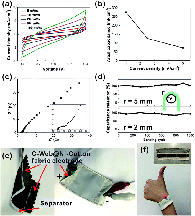
To demonstrate the practical application of the C-web@Ni–cotton fabric electrode, we further fabricated solid-state supercapacitor fabric devices using a polyvinyl alcohol/lithium chloride (PVA/LiCl) gel electrolyte. As shown in Fig. 4a and b, the solid-state device exhibits a high areal capacitance of 275.8 mF cm−2 at 1 mA cm−2 with a low internal resistance. Since good flexibility is an important issue for wearable applications,15 the bending test of the supercapacitor fabric was conducted under two small bending radii (r = 2 mm and 5 mm) (Fig. 4c). The device showed excellent electrochemical stability after bending for 1000 cycles at r = 5 mm. After bending at r = 2 mm for another 1000 cycles, the capacitance of the fabric device still retained 92% of the original value. These solid-state supercapacitor fabrics can be readily encapsulated and integrated into wearable forms by conventional textile processing, e.g., sewing technology. Fig. 4e demonstrates a large supercapacitor fabric (active area 4 cm × 4 cm), which is enclosed with a non-conductive fabric through the sewing technique (Movie 1†). CV analysis proves that the device capacitance remains stable before and after sewing (Fig. S5†). In another example, we connected three pieces of supercapacitors and sewed them into one wearable wristband, which could readily power a light-emitting diode with a turn-on voltage of 1.6 V (Fig. 4f).
Conclusion
In conclusion, we have reported a cost-effective and continuous one-step direct electrospinning method for fabricating high-performance flexible and wearable supercapacitor fabrics. The key novelty is to use wearable Ni–cotton as a conductive collecting substrate, on which a high concentration of MWCNTs can be directly electrospun to form a wearable C-web@Ni–cotton electrode at room temperature, without the need for any post-treatment. This enables the formation of an interconnected MWCNT framework throughout the electrospun nanofiber web, ensuring the high electrical conductivity and ion accessibility of the fabric electrode. Supercapacitor fabrics assembled with the as-made C-web@Ni–cotton electrodes, both in the liquid state and solid state, show high electrochemical performances, when compared with other fabric-based supercapacitors reported in the literature (Fig. 5 and Table S1†). More importantly, these supercapacitor fabrics could be easily integrated into wearable forms by using simple and conventional sewing technology. Considering the wide accessibility, high scalability, and good variability of the electrospinning technique, we believe that there still exists a large room for improving the performance of the supercapacitor fabrics, which are very likely to become ideal integrated energy-storage devices for next-generation wearable electronics.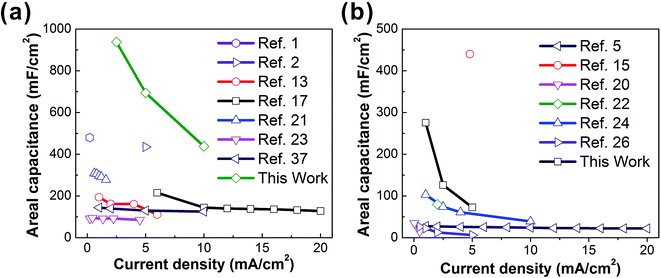 | ||
| Fig. 5 Current density vs. areal capacitance of liquid-based (a) and solid-based (b) supercapacitor fabrics summarized in Table S1.† | ||
Acknowledgements
We acknowledge the Innovation and Technology Fund (Project No. ITS/380/14) and the Hong Kong Polytechnic University Studentship for financial support of this work.Notes and references
- L. Hu, M. Pasta, F. La Mantia, L. Cui, S. Jeong, H. D. Deshazer, J. W. Choi, S. M. Han and Y. Cui, Nano Lett., 2010, 10, 708–714 CrossRef CAS PubMed.
- K. Jost, C. R. Perez, J. K. McDonough, V. Presser, M. Heon, G. Dion and Y. Gogotsi, Energy Environ. Sci., 2011, 4, 5060–5067 CAS.
- K. Jost, G. Dion and Y. Gogotsi, J. Mater. Chem. A, 2014, 2, 10776–10787 CAS.
- S. Zhang and N. Pan, Adv. Energy Mater., 2015, 5, 1401401 Search PubMed.
- G. Wang, H. Wang, X. Lu, Y. Ling, M. Yu, T. Zhai, Y. Tong and Y. Li, Adv. Mater., 2014, 26, 2676–2682 CrossRef CAS PubMed.
- L. Liu, Z. Niu, L. Zhang, W. Zhou, X. Chen and S. Xie, Adv. Mater., 2014, 26, 4855–4862 CrossRef CAS PubMed.
- P. Simon and Y. Gogotsi, Nat. Mater., 2008, 7, 845–854 CrossRef CAS PubMed.
- J. Jiang, Y. Li, J. Liu, X. Huang, C. Yuan and X. W. Lou, Adv. Mater., 2012, 24, 5166–5180 CrossRef CAS PubMed.
- B. Wang, X. Fang, H. Sun, S. He, J. Ren, Y. Zhang and H. Peng, Adv. Mater., 2015, 27, 7854–7860 CrossRef CAS PubMed.
- G. Yu, L. Hu, M. Vosgueritchian, H. Wang, X. Xie, J. R. McDonough, X. Cui, Y. Cui and Z. Bao, Nano Lett., 2011, 11, 2905–2911 CrossRef CAS PubMed.
- M. Pasta, F. La Mantia, L. Hu, H. D. Deshazer and Y. Cui, Nano Res., 2010, 3, 452–458 CrossRef CAS.
- Y. Jiang, X. Ling, Z. Jiao, L. Li, Q. Ma, M. Wu, Y. Chu and B. Zhao, Electrochim. Acta, 2015, 153, 246–253 CrossRef CAS.
- W.-w. Liu, X.-b. Yan, J.-w. Lang, C. Peng and Q.-j. Xue, J. Mater. Chem., 2012, 22, 17245–17253 RSC.
- L. Liu, Y. Yu, C. Yan, K. Li and Z. Zheng, Nat. Commun., 2015, 6, 7260 CrossRef CAS PubMed.
- K. Jost, D. Stenger, C. R. Perez, J. K. McDonough, K. Lian, Y. Gogotsi and G. Dion, Energy Environ. Sci., 2013, 6, 2698–2705 CAS.
- W. L. Song, K. Song and L. Z. Fan, ACS Appl. Mater. Interfaces, 2015, 7, 4257–4264 CAS.
- W. Wang, W. Y. Liu, Y. X. Zeng, Y. Han, M. H. Yu, X. H. Lu and Y. X. Tong, Adv. Mater., 2015, 27, 3572–3578 CrossRef CAS PubMed.
- L. H. Bao, J. F. Zang and X. D. Li, Nano Lett., 2011, 11, 1215–1220 CrossRef CAS PubMed.
- L. Bao and X. Li, Adv. Mater., 2012, 24, 3246–3252 CrossRef CAS PubMed.
- L. Wang, X. Feng, L. T. Ren, Q. H. Piao, J. Q. Zhong, Y. B. Wang, H. W. Li, Y. F. Chen and B. Wang, J. Am. Chem. Soc., 2015, 137, 4920–4923 CrossRef CAS PubMed.
- J. Xu, D. Wang, L. Fan, Y. Yuan, W. Wei, R. Liu, S. Gu and W. Xu, Org. Electron., 2015, 26, 292–299 CrossRef CAS.
- A. Laforgue, J. Power Sources, 2011, 196, 559–564 CrossRef CAS.
- K. Wang, P. Zhao, X. Zhou, H. Wu and Z. Wei, J. Mater. Chem., 2011, 21, 16373–16378 RSC.
- W. C. Li, C. L. Mak, C. W. Kan and C. Y. Hui, RSC Adv., 2014, 4, 64890–64900 RSC.
- H. M. Zheng, T. Zhai, M. H. Yu, S. L. Xie, C. L. Liang, W. X. Zhao, S. C. I. Wang, Z. S. Zhang and X. H. Lu, J. Mater. Chem. C, 2013, 1, 225–229 RSC.
- P. Yang, X. Xiao, Y. Li, Y. Ding, P. Qiang, X. Tan, W. Mai, Z. Lin, W. Wu, T. Li, H. Jin, P. Liu, J. Zhou, C. P. Wong and Z. L. Wang, ACS Nano, 2013, 7, 2617–2626 CrossRef CAS PubMed.
- M. Conte, Fuel Cells, 2010, 10, 806–818 CrossRef CAS.
- Y. Yu, C. Yan and Z. J. Zheng, Adv. Mater., 2014, 26, 5508–5516 CrossRef CAS PubMed.
- X. Q. Liu, H. X. Chang, Y. Li, W. T. S. Huck and Z. J. Zheng, ACS Appl. Mater. Interfaces, 2010, 2, 529–535 CAS.
- R. S. Guo, Y. Yu, Z. Xie, X. Q. Liu, X. C. Zhou, Y. F. Gao, Z. L. Liu, F. Zhou, Y. Yang and Z. J. Zheng, Adv. Mater., 2013, 25, 3343–3350 CrossRef CAS PubMed.
- X. L. Wang, C. Yan, H. Hu, X. C. Zhou, R. S. Guo, X. Q. Liu, Z. Xie, Z. F. Huang and Z. J. Zheng, Chem.–Asian J., 2014, 9, 2170–2177 CrossRef CAS PubMed.
- Y. Yu, Y. K. Zhang, K. Li, C. Yan and Z. J. Zheng, Small, 2015, 11, 3444–3449 CrossRef CAS PubMed.
- H. Q. Hou, J. J. Ge, J. Zeng, Q. Li, D. H. Reneker, A. Greiner and S. Z. D. Cheng, Chem. Mater., 2005, 17, 967–973 CrossRef CAS.
- E. J. Ra, K. H. An, K. K. Kim, S. Y. Jeong and Y. H. Lee, Chem. Phys. Lett., 2005, 413, 188–193 CrossRef CAS.
- X. Mao, T. A. Hatton and G. C. Rutledge, Curr. Org. Chem., 2013, 17, 1390–1401 CrossRef CAS.
- J. J. Ge, H. Q. Hou, Q. Li, M. J. Graham, A. Greiner, D. H. Reneker, F. W. Harris and S. Z. D. Cheng, J. Am. Chem. Soc., 2004, 126, 15754–15761 CrossRef CAS PubMed.
- Y.-W. Ju, G.-R. Choi, H.-R. Jung and W.-J. Lee, Electrochim. Acta, 2008, 53, 5796–5803 CrossRef CAS.
- M. Inagaki, Y. Yang and F. Y. Kang, Adv. Mater., 2012, 24, 2547–2566 CrossRef CAS PubMed.
- F. Ko, Y. Gogotsi, A. Ali, N. Naguib, H. H. Ye, G. L. Yang, C. Li and P. Willis, Adv. Mater., 2003, 15, 1161–1165 CrossRef CAS.
- J. Cai, H. T. Niu, Z. Y. Li, Y. Du, P. Cizek, Z. L. Xie, H. G. Xiong and T. Lin, ACS Appl. Mater. Interfaces, 2015, 7, 14946–14953 CAS.
- M. D. Stoller and R. S. Ruoff, Energy Environ. Sci., 2010, 3, 1294–1301 CAS.
- Q. Guo, X. Zhou, X. Li, S. Chen, A. Seema, A. Greiner and H. Hou, J. Mater. Chem., 2009, 19, 2810–2816 RSC.
- C. Masarapu, H. F. Zeng, K. H. Hung and B. Wei, ACS Nano, 2009, 3, 2199–2206 CrossRef CAS PubMed.
- W. Wang, S. Guo, I. Lee, K. Ahmed, J. Zhong, Z. Favors, F. Zaera, M. Ozkan and C. S. Ozkan, Sci. Rep., 2014, 4, 4452 Search PubMed.
- S. Chaudhari, Y. Sharma, P. S. Archana, R. Jose, S. Ramakrishna, S. Mhaisalkar and M. Srinivasan, J. Appl. Polym. Sci., 2013, 129, 1660–1668 CrossRef CAS.
- Q. Liao, N. Li, S. Jin, G. Yang and C. Wang, ACS Nano, 2015, 9, 5310–5317 CrossRef CAS PubMed.
- M. C. Biesinger, B. P. Payne, L. W. M. Lau, A. Gerson and R. S. C. Smart, Surf. Interface Anal., 2009, 41, 324–332 CrossRef.
- M. R. Sturgeon, M. H. O'Brien, P. N. Ciesielski, R. Katahira, J. S. Kruger, S. C. Chmely, J. Hamlin, K. Lawrence, G. B. Hunsinger, T. D. Foust, R. M. Baldwin, M. J. Biddy and G. T. Beckham, Green Chem., 2014, 16, 824–835 RSC.
- A. D. Bokare, R. C. Chikate, C. V. Rode and K. M. Paknikar, Appl. Catal., B, 2008, 79, 270–278 CrossRef CAS.
- L. Zhang, Q. Ding, Y. Huang, H. Gu, Y.-E. Miao and T. Liu, ACS Appl. Mater. Interfaces, 2015, 7, 22669–22677 CAS.
Footnote |
| † Electronic supplementary information (ESI) available. See DOI: 10.1039/c5ta09309k |
| This journal is © The Royal Society of Chemistry 2016 |

