
 Open Access Article
 This Open Access Article is licensed under a
 Creative Commons Attribution 3.0 Unported Licence
Sulfur/carbon cathode material chemistry and morphology optimisation for lithium–sulfur batteries†
Tayeba Safdar ab and
Chun Huang*abc
ab and
Chun Huang*abc
aDepartment of Materials Imperial College London, London SW7 2AZ, UK. E-mail: a.huang@imperial.ac.uk
bThe Faraday Institution Quad One, Becquerel Ave, Harwell Campus, Didcot, OX11 0RA, UK
cResearch Complex at Harwell Rutherford Appleton Laboratory, Didcot, OX11 0FA, UK
First published on 26th September 2024
Abstract
Lithium–sulfur batteries (LSBs) are a promising alternative to lithium-ion batteries because sulfur is highly abundant and exhibits a high theoretical capacity (1675 mA h g−1). However, polysulfide shuttle and other challenges have made it difficult for LSBs to be commercialised. Here, a sulfur/carbon (S/C) composite was synthesised and cathodes were fabricated via scalable melt diffusion and slurry casting methods. Carbon nanoparticles (C65) were used as both sulfur host and electrical additive. Various carbon ratios between the melt-diffusion step and cathode slurry formulation step were investigated. An increased amount of C65 in melt-diffusion led to increased structural heterogeneity in the cathodes, more prominent cracks, and a lower mechanical strength. The best performance was exhibited by a cathode where 10.5 wt% C65 (TC10.5) was melt-diffused and 24.5 wt% C65 was externally added to the slurry. An initial discharge capacity of ∼1500 mA h g−1 at 0.05C and 800 mA h g−1 at 0.1C was obtained with a capacity retention of ∼50% after 100 cycles. The improved electrochemical performance is rationalised as an increased number of C–S bonds in the composite material, optimum surface area, pore size and pore volume, and more homogeneous cathode microstructure in the TC10.5 cathode.
1. Introduction
Recent rises in average global temperatures and pollution have brought forth the consequences of abusing fossil fuels to meet the increasing energy demands. The severity of the damage and projected results (if fossil fuels are used at the current rate) have caused serious concerns about the sustainability of the planet. This has led to various investigations into alternate energy options and thus shifting the fuel focus to renewable methods to find sustainable solutions for the ever-increasing energy demands. As a consequence, batteries have gained immense popularity. Over the last decade the applications of batteries have attracted attention across many industries such as electric transportation and electrical energy storage from intermittent renewable sources. With lithium-ion batteries (LIBs) gradually reaching their physicochemical limits,1 the research focus is shifting towards next generation battery chemistries with the aim to develop batteries that are able to provide a balance between performance, cost and sustainability.2Lithium–sulfur batteries (LSBs) have shown great promise due to their high energy density, low cost and natural abundance of sulfur element. Sulfur is one of the most abundant materials on earth. LSBs have a theoretical capacity of 1675 mA h g−1 and energy density of 2600 W h kg−1 as opposed to 300 mA h g−1 and 265 W h kg−1 for conventional LIBs with oxide-based cathodes.3 Conventional LSBs use liquid electrolytes, commonly comprised of Li salts and solvents to act as a charge transfer medium and ionic conductor.4 Theoretically LSBs provide an excellent solution to the current challenges of LIBs. However, LSBs are held back because they exhibit a poor capacity retention, short lifetime and large volume expansions (up to 22%).4,5 The presence and extent of these challenges are significantly increased due to the polysulfide (PS) shuttle mechanism causing a domino effect and significantly reducing the efficiency of the batteries.6
During the discharge cycle, Li metal anode is oxidised to from Li+ ions. These diffuse across the electrolyte to the cathode where sulfur, S8, is reduced to lithium sulfide (Li2S). The redox reactions of first discharge cycle can be summarised in four main stages.7,8 Stage 1 occurs during initial discharge process. The bonds between the sulfur rings are broken and long PS chains are formed of Sx2− (4 ≤ x ≤ 8). In the second stage long PS chains are disassociated from Sx2− (4 ≤ x ≤ 8) to Sy2− (1 ≤ y ≤ 3). In stage 3 (third phase of discharge cycle) S32− chains are reduced to S22−. In the 4th stage, final stage of the discharge cycle, S22− is broken down to S2−. In the charge cycle, Li+ ions move back to anode whilst being reduced to Li metal by accepting electrons from the external circuit, Li2S is oxidised back to elemental sulfur by losing electrons. Sulfur will go through solid–liquid–solid phase changes during charging and discharging. When solid state S8 is discharged to a high order PS, it will dissolve in the electrolyte and react with Li anode to form low order PS,9 short PS chains are insoluble in liquid electrolyte. The diffusion of high and low order PS in and out of the electrolyte is what causes the shuttle effect.3,10 As S8 atoms are arranged in a cyclic ring, the bonds between the atoms can be associated and disassociated in various patterns. This instigates unwanted and complicated redox reactions, making it hard to exactly predict what type of PS will be formed.11–13
When high order PS reacts with Li anode, low order PS is formed and can be deposited on the Li anode and sulfur cathode. Thus, excessive solid electrolyte interface (SEI) is formed at the electrode interphase, restricting Li+ pathway and blocking access to sulfur active material,14 causing a non-uniform deposition of Li.15 As a result, SEI cracks into the electrolyte, continuing the cycle of reaction between Li anode, formation of new SEI and electrolyte components.14,16,17 Since Li+ pathways are constantly being blocked, damaged or changed, the battery performance after first few discharge cycles is significantly impacted. Battery then suffers from lowered ionic conductivity, volume expansion as the reaction chemistry can be unpredictable, shorter lifetime as well as corrosion and loss of active material.18–21
Many studies have focused on either eliminating or mitigating the shuttle effect. This can be achieved via adding PS inhibiting additives to liquid electrolyte or modifying electrode and separators structures by adding polar materials (e.g. O and N incorporated in polymers),22–25 adding functional groups and/or designing composites (e.g. mesoporous titanium nitride – sulfur),26 use of vulcanised polymer structures like polypropylene,2,27 single walled carbon nanotube coatings on separators,28 adding interlayers to prevent migration of PS to the Li anode,29 introducing various carbon structures like nanotubes, nanofibers, carbon aerogels30–32 to trap PS chains, etc. Solid-state electrolyte may also reduce the shuttling effect due to the lack of production of high order long chain PS, so side and unwanted reactions in conversion of S8 to Li2S may be reduced (depending on the reaction between solid-sate electrolyte, SEI formed and electrode).2,33–35
Carbon-based sulfur cathodes are being researched, more specifically focusing on the type of carbon and the role it plays. It can be used to enhance the electrical conductivity, act as a sulfur host or a part of a copolymer to suppress the shuttle effect. Carbon nanotubes (CNTs), graphene and porous carbons (macro- (>50 nm), meso- (2–50 nm)- and microporous (<2 nm)) are amongst the commonly used for sulfur carbon (S/C) cathode modification and optimisation. Materials such Super P, carbon black C65 and C45 are used in current LIBs and have desirable properties to be used as part of LSB cathodes.36,37 Their high surface area, mechanical properties, and good electrical conductivities possess a good solution to the insulation property of elemental sulfur. These conductive porous carbons are not part of active material and do not participate in the redox chemical reactions. Therefore, careful consideration is needed when deciding the amount used as less is preferable for an overall high energy density at the battery cell level.37 Due to this, there is always a trade-off between how much sulfur content a good S/C cathode should contain.38 Many studies vary sulfur wt% between 40 and 70 wt% (ref. 39–46) and achieve discharge capacities between ∼500–900 mA h g−1 with ∼50–70% capacity retention over 50–150 cycles. This paper focuses on utilising already existing carbon materials and investigating the balance between the carbon host material in the chemical composition of cathode composite material during synthesis and the electrical conductivity enhancer in the formulation of cathode suspension during slurry coating.
Currently, synthesis of S/C composites is achieved either via melt diffusion or solution-based methods. Melt diffusion is employed with the intention of trapping sulfur into the porous/fibrous carbon structure. It is usually carried out by mixing and heating sulfur and carbon powders. When heated, sulfur has a relatively low viscosity and high mobility, therefore making it easier to be loaded into carbon pores through capillary forces. In solution-based methods organic solvents like carbon disulfide (CS2), toluene, xylene or dimethyl sulfoxide are used to dissolve sulfur followed by drying the solution to obtain S/C powder composites. In other cases, thiosulfate or sulfides are mixed with carbon solution (such as graphene oxide) and reacted with an acid (such as hydrochloric acid) to form S/C composites which are dried to obtain as powders.47–52 The solution-based methods usually involve the use of toxic chemicals. Another approach is sulfur vapour deposition (SVD) where sulfur powder is evaporated in a furnace at temperatures of 300–600 °C under a certain atmosphere, commonly used argon, where the argon carrier gas helps the sulfur vapour travel forward to cooler part of the furnace so it can be deposited on the substrate (commonly used stainless steel, carbon structures or current collector).53,54 This technique can allow for binder free cathodes.55 However, SVD involve the use of sulfur vapour at elevated temperatures posing increased safety concerns. SVD also has limitations of involving the use of specialist equipment and being energy intensive.52,56–60 Based on these safety concerns and to eliminate the use to toxic chemicals as much as possible, this paper implements the use of dry melt-diffusion method without any toxic organic solvents to from S/C composites to make LSBs more sustainable for industrial applications.
2. Results and discussion
2.1. Morphology and mechanical properties
S/C composite was synthesised first via melt diffusion of sulfur and C65 to infuse sulfur onto the carbon structure. Cathodes were then fabricated by suspending the S/C composite with C65 in 1-methyl-2-pyrrolidinone (NMP) solvent to make a slurry followed by slurry coating, i.e. C65 was used both as a sulfur host in the composite material and as an electrical additive in the cathode structure, therefore C65 was added in two different stages. Fig. 1 shows a schematic of how the material synthesis and electrode fabrication were carried out. | ||
| Fig. 1 Schematic of cathode synthesis. | ||
The fabricated cathodes thickness was kept constant at 45 μm. This was achieved through doctor blade coating (70–55 μm) followed by calendaring. The total wt% of C65 was maintained constant at 35 wt% in each cathode while the proportion of treated carbon (TC, melt diffused carbon with sulfur) and non-treated carbon (NTC, externally added carbon in cathode slurry) was varied. Table 1 shows 5 different cathode configurations made with their respective notations, mass loading and density at the same thickness. The density of the cathode was increased from TC3.5 to TC31.5 with the amount of TC. Additionally, TC3.5 to TC17.5 exhibited a gradual increase in density and almost no change in mass loading, while steep increases in both mass loading and density were observed with TC24.5 and TC31.5. This was largely attributed to the cathode slurry properties and an increased amount of particle settling in higher TC slurries, leading to inhomogeneous casting of the slurry. High mass loadings (>2 mg cm−2) in S/C cathodes can cause fractures, delamination, enhanced shuttle effect and slow reaction kinetics,61 therefore many preliminary studies keep mass loadings low (<2 mg cm−2).62 For this study, all the mass loadings were kept below 3 mg cm−2 with the aim of first determining optimum cathode ratio between sulfur active material, carbon host and electrical additive. Once a standard cathode configuration is achieved, higher mass loadings can be investigated to overcome the stated challenges of poor mechanical properties and slow redox reactions.63–66
| Step 1: treated carbon (TC wt%) | Step 2: non-treated carbon (NTC wt%) | Cathode notation | Mass loading (mg cm−2) | Thickness (μm) | Density (mg cm−3) |
|---|---|---|---|---|---|
| 3.5 | 31.5 | TC3.5 | 1.20 | 45 | 477 |
| 10.5 | 24.5 | TC10.5 | 1.23 | 45 | 495 |
| 17.5 | 17.5 | TC17.5 | 1.23 | 45 | 504 |
| 24.5 | 10.5 | TC24.5 | 2.35 | 45 | 946 |
| 31.5 | 3.5 | TC31.5 | 2.67 | 47 | 1020 |
Electrode microstructure and physical properties are heavily governed by the slurry suspension properties. Achieving a desirable suspension depends on many factors such as slurry composition, active material properties, type of conductive agent used, as well as casting and drying procedures.67 Scanning electron microscopy (SEM) images in Fig. 2a show that as the TC ratio increased, the particle distributions in the cathode microstructure became more uneven and the cracks became more prominent. TC31.5 exhibited the highest degree of physical defects with increased heterogeneous deposition of cathode composite material across the current collector. This may be because as the amount of C65 treated with sulfur increased, the cathode slurry became more unstable. Energy dispersive spectroscopy (EDX) mapping in Fig. 2b displays pockets of sulfur in various sizes which were more prominent in higher TC cathodes. TC24.5 and TC31.5 had the highest amount of sulfur insulation pockets. These were formed because some sulfur that was loaded on carbon recrystallised during the melt diffusion process.
 | ||
| Fig. 2 (a) SEM images of the magnified surface morphology of different types of cathodes; (b) overview SEM images and the corresponding EDX elemental mapping of the cathode surface morphology. Fig. S1 in ESI† shows SEM images of TC10.5 cathode film and vs. TC10.5 composite powder. Table ST1 in ESI† shows EDX mass and atomic% of all cathode samples. | ||
Fig. S2–S5 in the ESI† shows the adsorption and desorption isotherms and surface areas measured by the Brunauer, Emmett and Teller (BET) method for all TC cathodes, pure sulfur, pristine C65, and heat treated C65. Table 2 summaries the specific surface area (SSABET), pore volume and average pore size conducted on the different TC cathode composites, pristine C65, heated C65 (HC65; heated at 155 °C for 12 h) and pristine sulfur. SSABET of C65 was measured to be 65 m2 g−1 which matched with literature and industrial values.68 A decrease in SSABET was observed for HC65 compared with C65, suggesting a small change in carbon microstructural arrangement after heating. Both C65 and HC65 exhibited a type II isotherm which is typical of microporous (5–50 nm pores) samples. Pure sulfur as expected had the lowest SSABET and pore volume, confirming the non-porous characteristics. TC31.5 exhibited the highest SSABET (0.49 m2 g−1), pore size (28 nm), and pore volume (0.0041 cm3 g−3) among the different TC cathodes. An ideal S/C cathode should exhibit a high enough surface area to promote and favour S8 reduction to Li2S and be porous enough to trap insoluble PS chains whilst allowing diffusion of long PS chains to establish favourable reaction kinetics.69 These properties are best displayed by TC10.5 where a high SSABET of 0.45 m2 g−1 was combined with smaller pore width and volume (14 nm and 0.0028 cm3 g−1).
| Specific surface area (SSABET) (m2 g−1) | Adsorption pore volume (cm3 g−1) (p/po = 0.99) | Average pore width (nm) | |
|---|---|---|---|
| Pristine C65 | 64.90 | 0.1897 | 12 |
| HC65 | 60.00 | 0.1873 | 12 |
| TC3.5 | 0.37 | 0.0018 | 9 |
| TC10.5 | 0.45 | 0.0028 | 14 |
| TC17.5 | 0.32 | 0.0021 | 23 |
| TC24.5 | 0.32 | 0.0020 | 14 |
| TC31.5 | 0.49 | 0.0041 | 28 |
| Pure sulfur | 0.16 | 0.0006 | 10 |
2.2. Physicochemical properties
Raman spectroscopy was carried out to further understand bond changes that occurred in C65 across the different TC samples. D band is the result of out of plane vibrations attributed to the structural defects. The D band peak occurring at 1347 ± 3 cm−1 represents disorder in C–C bonds and denotes defects.70–73 The D band peak was observed at 1347 cm−1 instead of 1350 cm−1 for conventional carbon materials such as graphite because C65 contains an increased number of sp3 carbon atoms. The bond length of sp2 C–C (∼1.33 Å) is shorter than C–C sp3 bond length (∼1.54 Å), longer bond length contributes to a lower wavelength in Raman spectra.74–77 The G band peak occurring at 1595 ± 3 cm−1 represents the first order scattering of sp2 carbon atoms and denotes graphitic bonds. The scattering is caused by in-plane vibrations of sp2 hybridised carbon atoms.68,78 Raman spectroscopy was carried out on all TC samples along with 100% C65 heat treated under the same conditions (Fig. 3a). Higher ID/IG ratio correlates to more structural defects present on carbon sites. Since C65 is mainly amorphous carbon, it is expected to have a relatively high ID/IG value where the presence sp3 carbon is dominant over graphitic sp2 carbon. Defects can be categorised into intrinsic and extrinsic. Intrinsic defects are formed by sp3 hybrid carbon atoms.79,80 Extrinsic defects are formed because of electronegative heterogenous atoms combined with carbon, leading to defects being induced into the cathode composite.81,82 This is usually achieved via introducing functional groups (such as N, O,83–85 nickel nanoparticles,86 metal oxides, metal sulfides, metal carbides and metal nitrides),87–92 surface modification or in this case carbon sulfur (C–S) bonds (leading to strong chemical adsorption of PS chains through increased surface polarity). | ||
| Fig. 3 (a) Raman D and G peaks for different TC cathodes, HC65 and pristine C65; (b) XRD spectrum of pristine C65 and HC65. | ||
The ID/IG ratio was 0.97 and 0.81 for pristine C65 and HC65, respectively. This suggests that heat treating C65 at various temperatures for prolonged periods of time can reduce the number of defects present on the carbon surface and form some graphitic bonds.93,94 Fig. 3b shows X-ray diffraction (XRD) patterns of pristine C65 and HC65 (Fig. S6† shows the XRD patterns of all TC cathodes). Three main peaks were at 24.2°, 42.5° and 49.6°. The first two were the response of [002] and [011] planes, respectively.95 The peak occurring at 49.6° could correspond 10L which would cover single peak representing [100] and [101] planes. As there were no separate peaks for [100] and [101], this confirms the presence of turbostratic structures in C65.96 Since XRD shows crystalline phases, the XRD patterns here only show the crystalline structure with ordered bonds for both samples. Nevertheless, the peaks are consistent with most carbon black materials where the carbon atom layer is not fully stacked.96
Table 3 shows all TC samples have ID/IG ratio higher than HC65, indicating the reaction and formation of bonds between sulfur and carbon most likely at the defective sites of C65 during the melt diffusion process. The ratio amongst TC samples is a combination of naturally occurring intrinsic C65 defects along with extrinsic defects induced from C–S bonds. The presence of extrinsic defects promote redox reactions and chemical adsorption of PS chains, whereas intrinsic defects promote physical adsorption of PS chains.97 Therefore, higher ratio means more extrinsic defects being induced via C–S bonds. In some cases, sulfur can sit in these sites rather than forming homogenous C–S bonds through out.98 TC10.5 had the highest ratio of 0.88, and the ID/IG ratio exhibited a steady decline after TC10.5 to TC31.5. As the amount of C65 heat treated with sulfur increased, the number of C–S bonds formed increased until TC10.5, hence, the high ratio of TC10.5 reflected the highest number of extrinsic defects (promoting redox kinetics as well as trapping PS chains). After TC10.5, the number of C–S bonds formed did not change, rather the intrinsic defects from C65 were filled/blocked by crystallised sulfur (sulfur insulation pockets shown in EDX mapping in Fig. 2b). Since more defect sites were blocked with increasing TC, the ID/IG ratio decreased as TC increased from 10.5 to 31.5. Thus, it can be inferred that S/C cathodes with more defects and C–S bonds are more favourable in the lithium–sulfur battery configuration to trap more PS chains and improve the LSB performance.
| Sample | ID/IG |
|---|---|
| Pristine C65 | 0.97 |
| HC65 | 0.81 |
| TC3.5 | 0.84 |
| TC10.5 | 0.88 |
| TC17.5 | 0.86 |
| TC24.5 | 0.85 |
| TC31.5 | 0.83 |
X-ray photoelectron spectroscopy (XPS) was carried out on all TC cathodes to study and evaluate the changes in bonds. Fig. 4 shows the spectra of carbon C 1s (Fig. 4a) and sulfur S 2p (Fig. 4b) for TC10.5, the profiles were deconvoluted into relevant Gaussian–Lorentzian peaks. The C 1s and S 2p spectra for the other TC cathodes are shown in Fig. S9a and b.† As C65 is a zero-dimensional amorphous soft carbon with turbostratic structure, C65 carbon would consist of a significant amount of sp2 carbon peak at around 284.5 eV, representing C–C bonds present due to the aromatic clusters of C65.99,100 The C–C peak corresponding to C 1s bond was also in the same position but a lower amount. The C–O–C/C–S peak was observed at 286.5 eV. The presence of O may be due to the presence of defects and the melt diffusion process which was performed under weak vacuum conditions. The peak at 290.7 eV indicates the presence of CFx due to the bond between C65 and polyvinylidene fluoride (PVDF) binder in the cathode. The strong appearance of the CFx peak indicates that drying duration and increases in drying temperature can lead to PVDF binder to rise from the bulk of the cathode to the surface.101 According to Pauling scale, the electronegativities of carbon and sulfur are in very close proximity to each other (2.55 and 2.58 respectively), making it extremely difficult to distinguish between carbon, sulfur and various carbon sulfides (CSx and CS2).102 Therefore, it is difficult to track the exact changes in carbon–sulfur bond that are present. Fig. 4b shows the sulfur 2p spectra consisted of two main peaks of 2p3/2 at 164 eV and 2p1/2 at 165.1 eV. The 164 eV peak corresponded to elemental terminal sulfur bonds of S–S or C–S, where sulfur could be linked to carbon rings or an oxygen atom.103,104 The O1s spectra for all TC cathodes in Fig. S10† show no presence of O–S bonds, therefore, the sulfur 2p1/2 peak can be regarded as CS species, this aligns well with the C–S peak in C1s in Fig. 4a.105 The sulfur 2p1/2 peak corresponds to C–S–C bond with sulfur being the central atom.106 TC10.5 also exhibited the higher atomic% of C–S/C–O–C bond in C 1s spectra, confirming an increased presence of C–S bonds and defects in S/C cathode.
 | ||
| Fig. 4 XPS peaks for TC10.5 with (a) C 1s; (b) high resolution S 2p spectra. | ||
2.3. Electrochemical properties
Fig. 5a shows the cyclic voltammogram of all TC cathodes at 0.05 mV s−1 scan rate before cycling in coin cell configurations. Two distinct redox peaks (2.3 and 1.9 V) during discharge were present for lower TC (TC3.5–17.5), representing the two-step reduction to S8 to Li2S.99,107,108 Fig. 5b shows the charge discharge profiles of TC24.5 and TC31.5 at 0.5C. The peak at 2.3 V in the cyclic voltammogram was attributed to the first plateau of long chain PSx chains formation (4 < x< 8) in the discharge profile, and the peak at 1.9 V in the cyclic voltammogram corresponded to the second plateau in the discharge curve for the conversion of long chain PS chains to short chain PSx (1 < x< 3). Fig. 5a shows the two reduction peaks in cyclic voltammograms for TC24.5 and TC31.5 were broad and exhibited small shifts from the expected peak positions. This could be the combined result of slow reaction kinetics, where two step reduction of S8 is slow and inefficient. The broad peak could also represent the simultaneous reduction of S8 to Li2S. In such cases, the obtained cyclic voltammogram peaks are not well defined and/or are quite broad.109–111 Fig. 5b shows both TC24.5 and TC31.5 profiles are noisy, indicating increased resistance within the cell arising from PS chains and their side reactions. | ||
| Fig. 5 (a) Cyclic voltammograms at 0.05 mV s−1 scan rate before cycling; (b) initial charge discharge profiles at 0.5C; (c) discharge capacity during rate capability testing; (d) discharge capacity and coulombic efficiency at 0.1C during 50 cycles. All tests were performed for all TC cathodes in coin cell configurations at room temperature. | ||
Fig. 5c shows lower TC cathodes (3.5, 10.5, and 17.5) exhibited better rate capabilities as the (dis)charge rates increased, TC10.5 exhibited the best rate capability. As the amount of externally added C65 in lower TC cathodes was greater, the cathode structure provided a better electron percolation network compared with higher TC samples where more C65 was added and heat treated in the first synthesis step, leading to inhomogeneous slurry and particle deposition during the second electrode coating step.112 The poor capacity and rate capability of higher TC cathodes were because of the increased mechanical defects (large cracks) and uneven TC particles distributions in the higher TC cathode microstructure, with the most sulfur insulation pockets in TC31.5 which slowed down redox reactions,98 as shown in the SEM and EDX images in Fig. 2. Increased inhomogeneity in microstructure led to limited access to active materials, decreased utilisation of active material, poor electrical percolation network, and hindered Li+ diffusion pathways.
Fig. 5d shows discharge capacity retention after 50 cycles at 0.1C. Higher TCs had better capacity retention ∼70%, however, their starting capacities were also lower (600 and 450 mA h g−1 for TC24.5 and TC31.5, respectively). TC10.5 had a high starting discharge capacity of ∼750 mA h g−1 and had a capacity retention of 46%. Fig. 5c shows the rate capability testing and when the C rate returned to 0.05C, TC10.5 exhibited a discharge capacity of 1000 mA h g−1 whilst TC24.5 and 31.5 displayed a discharge capacity of ∼550 and ∼300 mA h g−1, respectively. Overall, TC10.5 displayed consistent performance at different C rates and the highest discharge capacity at the end of 50 cycles. This is also supported in stability test where TC3.5, TC10.5 and TC31.5 continued cycling to complete 100 cycles (0.1C, shown in Fig. S11†). TC10.5 displayed a stable discharge capacity of ∼300 mA h g−1 at the end of 100 cycles whereas TC31.5 and TC3.5 exhibit a decrease in discharge capacity of ∼230 mA h g−1 and ∼100 mA h g−1, respectively, at the end of 100 cycles.113–115
Across literature numerous methods and configurations of sulfur cathodes have been explored with the aim of improving lithium sulfur battery performance. Many studies aim to achieve this via a combination of cathode optimisation, electrolyte additives, separator modification and/or different anode configurations. Popular cathode studies involve carbon nanotubes as sulfur host. Li et al.116 reported sulfur/carbon nanotubes as one of their cathodes, exhibiting ∼55% capacity after ∼100 cycles at 0.5C. These results are similar to the results exhibited by TC10.5 (Fig. S11†). Similarly, Han et al.117 reported multiwalled carbon nanotube/sulfur cathodes exhibiting capacity retentions between ∼31–40% after 100 cycles along with poor rate capability performance of 400 mA h g−1 at 0.1C as opposed to ∼600 mA h g−1 of TC10.5. Marangon et al.118 exhibited a capacity loss of ∼40% at ∼0.1C over 100 cycles. Qiao et al.119 report their sulfur/carbon nanotube cathode of 60–70 wt% sulfur with a capacity retention of 40–50% after 100 cycles at 0.2C. Though there are studies that demonstrate higher discharge capacities and better long-term stability120–122 a lot of variations are present across literature, e.g. using different ratios in heat treatment (such as sulfur![[thin space (1/6-em)]](https://www.rsc.org/images/entities/char_2009.gif) :carbon wt. ratios of 3:7, 5:5, 4:6, 7:3 etc) without explaining the effect66,123–125 and almost all studies across literature with similar cathode design use at least 10 wt% as binder content in the cathode. TC10.5 has shown comparable performance of similar capacity retention after 100 cycles with only 5 wt% binder to reduce insulation/non-conductive elements in the cathode. Furthermore, all the capacities reported in this paper were calculated based on the total mass of the cathode including the binder and carbon which more realistically represents the performance in practical batteries. The aims of this study was to (i) find the optimum ratio of carbon black that can undergo a simple heat treatment with sulfur to form the sulfur/carbon composite; (ii) demonstrate successful performance of all the cathodes in this study with the use of only 5 wt% binder to reduce insulation/non-conductive elements in the cathode; and (iii) demonstrate synthesis of sulfur/carbon cathode utilising the slurry casting method that is compatible to the existing lithium ion battery fabrication in industry.
:carbon wt. ratios of 3:7, 5:5, 4:6, 7:3 etc) without explaining the effect66,123–125 and almost all studies across literature with similar cathode design use at least 10 wt% as binder content in the cathode. TC10.5 has shown comparable performance of similar capacity retention after 100 cycles with only 5 wt% binder to reduce insulation/non-conductive elements in the cathode. Furthermore, all the capacities reported in this paper were calculated based on the total mass of the cathode including the binder and carbon which more realistically represents the performance in practical batteries. The aims of this study was to (i) find the optimum ratio of carbon black that can undergo a simple heat treatment with sulfur to form the sulfur/carbon composite; (ii) demonstrate successful performance of all the cathodes in this study with the use of only 5 wt% binder to reduce insulation/non-conductive elements in the cathode; and (iii) demonstrate synthesis of sulfur/carbon cathode utilising the slurry casting method that is compatible to the existing lithium ion battery fabrication in industry.
Fig. 6 shows electrochemical impedance spectroscopy (EIS) plots of TC10.5 and TC31.5 with the equivalent circuit used to fit the data. R1 corresponds to ohmic resistances of electrolyte, current collector and cell connections, R2 is the combined interfacial resistances (of Li+ diffusion) between the electrode surface and electrolyte, Q1 is the distributed capacitance of sulfur and lithium electrode surface layers, R3 is PS charge transfer resistance on the sulfur electrode, Q2 is the distributed double layer capacitance of cathode surface pores and W1 represents Warburg diffusion of Li+ ions.126–130
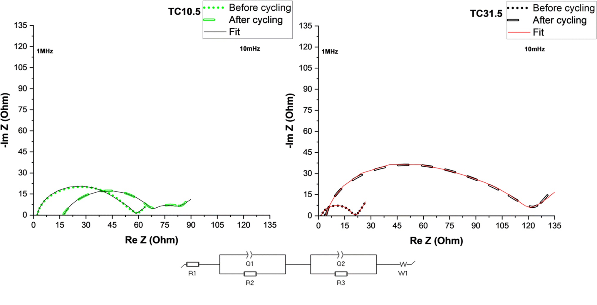 | ||
| Fig. 6 EIS plots of TC10.5 and 31.5 before and after 50 cycles at 0.1C. | ||
Table 4 displays detailed values of resistances before and after cycling for TC10.5 and TC31.5. Changes in R1 after cycling represent the amount of soluble PS chains present in the electrolyte.131 After 50 cycles, more soluble long chain PS were present in TC10.5 than TC31.5. Similarly interfacial resistance R2 is an indication of the amount of insoluble short chain PS that is deposited onto the electrodes. In TC10.5, R2 decreased from 11.9 to 10.9 Ω, highlighting the depletion in deposition of insoluble short chain PS at the interfaces, and thus, improving the Li diffusion and interfacial wettability.132 R2 for TC31.5 was tripled after cycling. Therefore, TC31.5 had a strong PS shuttle effect where access to sulfur active material and Li metal anode was blocked via constant formation of excessive unwanted SEI layer. Due to the presence of extrinsic induced defects and strong C–S bonds in TC10.5, there was a smaller increase in the charge transfer resistance, R3, before and after cycling when compared with TC31.5 where the R3 was almost 30 times greater after cycling. This aligned well with the hypothesis that the defective sites were being blocked by sulfur crystals. Electronic conductivity, from Table ST2,† was seen to increase with TC. Highest electronic conductivity was exhibited by TC31.5. Based on sulfur insulation pockets being predominantly present in higher TC, this was the unexpected result. Upon further inspection it was found that when C65 was heated at 155 °C for 12 hours, an increase in electronic conductivity was observed (almost 5 times higher). This clearly explains the unexpected trend of electronic conductivity increasing with TC, as the amount of HC65 was higher. In higher TC, though sulfur blocked pores and insulated the defects from being utilised, movement of electrons was faster due to network channels formed between heated C65 and C65 added in step 2 (shown in Fig. 1). Thus, a trade-off was required between enhancing electronic conductivity and the utilisation of sulfur active material and mitigation of PS shuttle to enhance battery performance.
| TC10.5 | TC31.3 | |||
|---|---|---|---|---|
| Pristine | After 50 cycles | Pristine | After 50 cycles | |
| R1 (Ω) | 2.15 | 17.16 | 1.64 | 4.08 |
| R2 (Ω) | 11.92 | 10.86 | 17.40 | 53.50 |
| R3 (Ω) | 43.85 | 51.14 | 2.11 | 61.50 |
| Q1 (Fs(a1-1)) | 3.81 × 10⁻⁴ | 4.76 × 10⁻³ | 6.10 × 10⁻⁶ | 5.74 × 10⁻⁶ |
| Q2 (Fs(a2-1)) | 4.01 × 10⁻⁶ | 1.88 × 10⁻⁵ | 6.37 × 10⁻³ | 1.69 × 10⁻⁴ |
Overall, TC10.5 had a medium surface area (0.45 m2 g−1), pore size (14 nm), and pore volume (0.0028 cm3 g−1) among all the TC cathodes from the BET results, which exhibited a high enough surface area to promote S8 reduction to Li2S and was porous enough to allow diffusion of long PS chains and trap insoluble PS chains. TC10.5 also had the highest ID/IG ratio of 0.88 from the Raman results and the highest atomic% of C/S bonds from the XPS results, indicating the presence of more C–S bonds increased chemical adsorption of PS chains, aided redox reactions at higher C rates and increased rate capability of LSBs.
3. Conclusions
Multiple ratios of C65 heat treated with sulfur were investigated to establish the optimum amount of carbon that was added in the composite cathode material during melt diffusion synthesis (step 1) and added in the cathode slurry during electrode coating (step 2) for LSBs. The homogeneity of the cathode slurry decreased with an increasing proportion of treated carbon in step 1. Higher TC (from 17.5 to 31.5) suspensions were more unstable, leading to inhomogeneous deposition of cathode particles in the resulting cathode microstructure. TC17.5 or higher led to denser cathodes with elevated mechanical damage (defined cracks) thus directly impacting the electrochemical performance of the cells. TC10.5 provided the best electrochemical response of an initial discharge capacity of ∼800 mA h g−1 at 0.05C, best rate capability and low impedance. This may be because TC10.5 exhibited the highest ID/IG ratio of 0.88 from Raman data and the highest atomic% of C/S bonds from XPS results, indicating the highest number of C/S bonds introduced from melt diffusion which promoted sulfur redox reactions and chemical adsorption of PS chains to reduce the PS shuttle effect while higher TC above 10.5 created more isolated sulfur pockets which were recrystallised during melt diffusion. TC10.5 also exhibited a medium, more optimum surface area, pore size and pore volume to facilitate long PS chain diffusion and trap insoluble short PS chains. This study demonstrated that good performing S/C composite cathodes were synthesised and fabricated by using commercially available starting materials and scalable methods. The dry melt diffusion method does not require the use of toxic solvents such as CS2, benzene or toluene in the conventional solution-based C/S composite synthesis method. The dry melt diffusion process also used a lower heating temperature of 155 °C (as opposed to some other studies of melt diffusion and that conduct melt diffusion and sulfur vapour deposition at 300–600 °C), making the processing more sustainable. Therefore, the synthesis process in this paper closely resembles current industrial slurry casting and cathode synthesis technology for lithium ion batteries and thus has the potential for scaling up using existing casting equipment.4. Experimental
4.1 Cathode fabrication
60 wt% sulfur and varying ratios of C65 were ground in a planetary ball mill in zirconium jars with 10 mm zirconium milling balls, with ball to powder ratio being 1:1 (v:v) at 250 rpm for 5 hours. To prevent oxidation of sulfur (due to the heat generated during mixing) the milling programme was set to run for 5 minutes followed by a rest period of 10 minutes to allow for adequate cooling of the powder. This is supported by the XRD data shown in Fig. S12.† Where no change in crystal structure was observed between the two samples. No change in structure was observed between powder that was milled in room atmosphere and one that was pack in airtight jar under Ar atmosphere. The milled powder was heat treated for 12 hours at 155 °C under vacuum conditions to make S/C composite (step 1). To make the cathodes, 5 wt% PVDF powder and non-heat treated C65 of different wt% were suspended homogeneously in 1-methyl-2-pyrrolidinone (NMP) solution first, and the S/C composite powder from step 1 was added. 5 wt% PVDF was used instead of report 10–8 wt% to reduce the insulation components in the battery. The slurry was cast onto aluminium foils and dried under the fume hood overnight then dried under vacuum at 60 °C for 1 hour. The dried cathodes were calendared (to reduce the thickness by 25–28%, ± 3%) before being cut into 16 mm discs. All the cathodes had an overall composition of S:C65:PVDF = 60:35:5 (wt%). Cathode thickness was controlled at 45 μm.
4.2 Physical and chemical characterisation
Cathode morphology was studied via SEM on Zeiss Sigma 300 at 5 keV, this was combined with energy dispersive X-rays (EDX) (15 keV) to study the distribution of sulfur and carbon on cathode surface. XPS was utilised to study the changes in C/S bonds using a Thermo Scientific K-alpha X-ray photoelectron Spectrometer. Measurements were conducted on cathode discs with 35 eV pass energy for high resolution C 1s and S 2p spectra, and Thermo Avantage software was used for data analysis. BET analysis (conducted in autosorb iQ3) was used to determine the specific surface area, Barrett, Joyner and Halenda (BJH) method was used to determine the pore size distribution and pore volume. All TC samples were degassed at 25 °C for 15 hours prior to conducting the measurements and 100% C65 samples were degassed at 300 °C for 12 hours. XRD (conducted on Bruker D2) was used to study the changes in crystal structure of the cathodes. Measurements were conducted between 5–70° with a step size of 0.01°. Raman study was conducted on a Reinshaw instrument utilising 532 nm excitation laser.4.3 Electrochemistry
Electrolyte was synthesised in an Ar glovebox by dissolving 1 M of lithium bis(trifluoromethanesulfonyl)imide (LiTFSI) and 0.8 M of lithium nitrate in 1:1 (v:v) 1,2 dioxlane and 1,2dimethoxyethane (DOL:DME) solvents. Both lithium salts were dried at 120 °C under vacuum before being transferred to glovebox. Both DME and DOL solvents were dried by placing molecular sieves (4 Å pore diameter) for 3 days and then filtered using PFTE syringe tips. Prior to use, molecular sieves were dried at 220 °C for 3 days and then transferred to glovebox. 16 mm diameter lithium chips were used as the anode, 19 mm diameter Celgard polypropylene 2400 was used as separator and 80 μL liquid electrolyte was used to assemble each CR2032 coin cell. All coin cells were rested overnight after assembly before carrying out electrochemical testing at room temperature. Galvanostatic charge and discharge and rate capability testing were performed on Arbin LBT20084. All the galvanostatic testing was carried out between the voltage range of 1.5–3 V. Different C rates of 0.05, 0.1, 0.3, 0.5, 0.7, 1, 2, 3 and 0.05C were evaluated. At each C rate the cell was (dis)charged 5 times in the order of the rates listed. All the cells were tested for 50 cycles at 0.1C. Cyclic voltammetry (CV) was conducted on pristine cells condition on Biologic BCS-128 at 0.05 mV s−1 scan rate. Electrochemical Impedance spectroscopy (EIS) was carried out in frequency range of 1 MHz–10 mHz at 10 mV sinus amplitude at open circuit voltage (∼2.2 V) on Biologic SP-300. Electronic conductivity of the cathode discs was measured using 2 point probe. DC voltages of 0.02, 0.06, 0.08, 0.12, 0.16 and 0.18 V were applied to the cathode which was sandwiched between two stainless steel electrodes to achieve an electrode blocking assembly. The current response at each voltage was recorded between 1–3 hours (or until a plateau was achieved). All measurements were carried at 25 °C.
Data availability
The data supporting this article have been included as part of the ESI.†Conflicts of interest
There are no conflicts to declare.Acknowledgements
The following funding is acknowledged: Faraday Institution Training Grant (FITG034), Faraday Institution research programme grants (FIRG060 and FIRG066), ERC Starting Grant (converted to UKRI funding EP/Y009908/1), UKRI EPSRC UKRI Innovation Fellowship (EP/S001239/1, EP/S001239/2), Faraday Institution Industry Fellowship (FIIF015), Imperial College London UKRI Impact Acceleration Account (EP/X52556X/1). BET measurements were conducted and analysed with the help of Patricia Carry at the Department of Chemical Engineering, Imperial College London.References
- C. P. Grey and D. S. Hall, Nat. Commun., 2020, 11, 6279 CrossRef CAS PubMed.
- S. L. Li, W. F. Zhang, J. F. Zheng, M. Y. Lv, H. Y. Song and L. Du, Adv. Energy Mater., 2021, 11, 2000779 CrossRef CAS.
- A. M. Suzanowicz, C. W. Mei and B. K. Mandal, Batteries, 2022, 8, 45 CrossRef CAS.
- X. M. He, J. G. Ren, L. Wang, W. H. Pu, C. Y. Jiang and C. R. Wan, J. Power Sources, 2009, 190, 154–156 CrossRef CAS.
- S. Walus, G. Offer, I. Hunt, Y. Patel, T. Stockley, J. Williams and R. Purkayastha, Energy Storage Mater., 2018, 10, 233–245 CrossRef.
- Y. X. Yin, S. Xin, Y. G. Guo and L. J. Wan, Angew. Chem., Int. Ed., 2013, 52, 13186–13200 CrossRef CAS PubMed.
- W. C. Ren, W. Ma, S. F. Zhang and B. T. Tang, Energy Storage Mater., 2019, 23, 707–732 CrossRef.
- Z. Lin and C. D. Liang, J. Mater. Chem. A, 2015, 3, 936–958 RSC.
- G. Babu, K. Ababtain, K. Y. S. Ng and L. M. R. Arava, Sci. Rep., 2015, 5, 8763 CrossRef CAS PubMed.
- D. Moy, A. Manivannan and S. R. Narayanan, J. Electrochem. Soc., 2015, 162, A1–A7 CrossRef CAS.
- Y. Diao, K. Xie, S. Z. Xiong and X. B. Hong, J. Electrochem. Soc., 2012, 159, A421–A425 CrossRef CAS.
- M. Wild, L. O'Neill, T. Zhang, R. Purkayastha, G. Minton, M. Marinescu and G. J. Offer, Energy Environ. Sci., 2015, 8, 3477–3494 RSC.
- H. Yamin, A. Gorenshtein, J. Penciner, Y. Sternberg and E. Peled, J. Electrochem. Soc., 1988, 135, 1045–1048 CrossRef CAS.
- R. Steudel and T. Chivers, Chem. Soc. Rev., 2019, 48, 4338 RSC.
- L. P. Hou, X. Y. Li, C. X. Bi, Z. X. Chen, Z. Li, L. L. Su, P. Shi, C. B. Jin, B. Q. Li, J. Q. Huang, X. Q. Zhang and Q. Zhang, J. Power Sources, 2022, 550, 232144 CrossRef CAS.
- H. P. Wu, H. Jia, C. M. Wang, J. G. Zhang and W. Xu, Adv. Energy Mater., 2021, 11, 2003092 CrossRef CAS.
- P. B. Zhai, L. X. Liu, X. K. Gu, T. S. Wang and Y. J. Gong, Adv. Energy Mater., 2020, 10, 2001257 CrossRef CAS.
- X. B. Cheng, J. Q. Huang, H. J. Peng, J. Q. Nie, X. Y. Liu, Q. Zhang and F. Wei, J. Power Sources, 2014, 253, 263–268 CrossRef CAS.
- Y. Diao, K. Xie, S. Z. Xiong and X. B. Hong, J. Power Sources, 2013, 235, 181–186 CrossRef CAS.
- A. Manthiram, Y. Z. Fu and Y. S. Su, Acc. Chem. Res., 2013, 46, 1125–1134 CrossRef CAS PubMed.
- M. Barghamadi, A. S. Best, A. I. Bhatt, A. F. Hollenkamp, M. Musameh, R. J. Rees and T. Rüther, Energy Environ. Sci., 2014, 7, 3902–3920 RSC.
- H. W. Chen, W. L. Dong, J. Ge, C. H. Wang, X. D. Wu, W. Lu and L. W. Chen, Sci. Rep., 2013, 3, 1910 CrossRef PubMed.
- L. F. Xiao, Y. L. Cao, J. Xiao, B. Schwenzer, M. H. Engelhard, L. V. Saraf, Z. M. Nie, G. J. Exarhos and J. Liu, Adv. Mater., 2012, 24, 1176–1181 CrossRef CAS PubMed.
- Y. Yang, G. H. Yu, J. J. Cha, H. Wu, M. Vosgueritchian, Y. Yao, Z. A. Bao and Y. Cui, ACS Nano, 2011, 5, 9187–9193 CrossRef CAS PubMed.
- W. Y. Li, Q. F. Zhang, G. Y. Zheng, Z. W. Seh, H. B. Yao and Y. Cui, Nano Lett., 2013, 13, 5534–5540 CrossRef CAS PubMed.
- Z. M. Cui, C. X. Zu, W. D. Zhou, A. Manthiram and J. B. Goodenough, Adv. Mater., 2016, 28, 6926–6931 CrossRef CAS PubMed.
- B. C. Yu, J. W. Jung, K. Park and J. B. Goodenough, Energy Environ. Sci., 2017, 10, 86–90 RSC.
- Z. H. Wei, Y. Q. Ren, J. Sokolowski, X. D. Zhu and G. Wu, Infomat, 2020, 2, 483–508 CrossRef CAS.
- T. Ali and C. Yan, ChemSusChem, 2020, 13, 1447–1479 CrossRef CAS PubMed.
- Y. C. Jeong, J. H. Kim, S. Nam, C. R. Park and S. J. Yang, Adv. Funct. Mater., 2018, 28, 1707411 CrossRef.
- X. L. Ji, K. T. Lee and L. F. Nazar, Nat. Mater., 2009, 8, 500–506 CrossRef CAS PubMed.
- Z. W. Zhang, Z. Q. Li, F. B. Hao, X. K. Wang, Q. Li, Y. X. Qi, R. H. Fan and L. W. Yin, Adv. Funct. Mater., 2014, 24, 2500–2509 CrossRef CAS.
- Q. C. Zhu, C. Ye and D. Y. Mao, Nanomaterials, 2022, 12, 3612 CrossRef CAS PubMed.
- Y. De Luna, M. Abdullah, S. N. Dimassi and N. Bensalah, Ionics, 2021, 1–24 Search PubMed.
- S. Chen, B. Ding, Q. Lin, Y. Shi, B. Hu, Z. Li, H. Dou and X. Zhang, J. Electroanal. Chem., 2021, 880, 114874 CrossRef CAS.
- Y. Y. Li, J. G. Shapter, H. Cheng, G. Y. Xu and G. Gao, Particuology, 2021, 58, 1–15 CrossRef CAS.
- M. E. Spahr, D. Goers, A. Leone, S. Stallone and E. Grivei, J. Power Sources, 2011, 196, 3404–3413 CrossRef CAS.
- S. Sawada, H. Yoshida, S. Luski, E. Markevich, G. Salitra, Y. Elias and D. Aurbach, Molecules, 2023, 28, 4568 CrossRef CAS PubMed.
- G. H. Kim, Y. J. Lee, J. W. Park, A. Raza, M. B. Raza, D. Kim, M. Park and H. Choi, Int. J. Electrochem. Sci., 2023, 18, 100217 CrossRef.
- J. Lim, J. Pyun and K. Char, Angew. Chem., Int. Ed., 2015, 54, 3249–3258 CrossRef CAS PubMed.
- J. Y. Hwang, H. M. Kim and Y. K. Sun, J. Electrochem. Soc., 2018, 165, A5006–A5013 CrossRef CAS.
- J. B. Albert Gröbmeyer, P. M. Bieker, M. Winter and M. Cristian Stan, Energy Technol., 2019, 1800789 CrossRef.
- J. B. Liao and Z. B. Ye, Batteries, 2018, 4, 22 CrossRef.
- C. Q. Zhang, Q. Lan, Y. T. Liu, J. L. Wu, H. X. Shao, H. Zhan and Y. F. Yang, Electrochim. Acta, 2019, 306, 407–419 CrossRef CAS.
- S. H. Yu, X. R. Feng, N. Zhang, J. Seok and H. D. Abruña, Acc. Chem. Res., 2018, 51, 273–281 CrossRef CAS PubMed.
- M. Agostini, J. Y. Hwang, H. M. Kim, P. Bruni, S. Brutti, F. Croce, A. Matic and Y. K. Sun, Adv. Energy Mater., 2018, 8, 1801560 CrossRef.
- X. H. Zhao, G. Cheruvally, C. Kim, K. K. Cho, H. J. Ahn, K. W. Kim and J. H. Ahn, J. Electrochem. Sci. Technol., 2016, 7, 97–114 CrossRef CAS.
- X. Liang, C. Hart, Q. Pang, A. Garsuch, T. Weiss and L. F. Nazar, Nat. Commun., 2015, 6, 5682 CrossRef PubMed.
- X. L. Ji, S. Evers, R. Black and L. F. Nazar, Nat. Commun., 2011, 2, 325 CrossRef PubMed.
- P. Adelhelm, P. Hartmann, C. L. Bender, M. Busche, C. Eufinger and J. Janek, Beilstein J. Nanotechnol., 2015, 6, 1016–1055 CrossRef CAS PubMed.
- S. Evers and L. F. Nazar, Chem. Commun., 2012, 48, 1233–1235 RSC.
- F. F. Zhang, X. B. Zhang, Y. H. Dong and L. M. Wang, J. Mater. Chem., 2012, 22, 25492 Search PubMed.
- S. Y. Zheng, Y. Chen, Y. H. Xu, F. Yi, Y. J. Zhu, Y. H. Liu, J. H. Yang and C. S. Wang, ACS Nano, 2013, 7, 10995–11003 CrossRef CAS PubMed.
- A. S. Alzahrani, M. Otaki, D. W. Wang, Y. Gao, T. S. Arthur, S. Liu and D. H. Wang, ACS Energy Lett., 2021, 6, 413–418 CrossRef CAS.
- M. Hakimi, A. B. Farahani, Z. Sanaee, S. Ghasemi and S. Mohajerzadeh, Mater. Res. Express, 2019, 6, 105514 CrossRef CAS.
- K. Fu, Y. P. Li, M. Dirican, C. Chen, Y. Lu, J. D. Zhu, Y. Li, L. Y. Cao, P. D. Bradford and X. W. Zhang, Chem. Commun., 2014, 50, 10277–10280 RSC.
- W. C. Ren, W. Ma, M. M. Umair, S. F. Zhang and B. T. Tang, Chemsuschem, 2018, 11, 2695–2702 CrossRef CAS PubMed.
- M. X. Wang, L. S. Fan, D. Tian, X. Wu, Y. Qiu, C. Y. Zhao, B. Guan, Y. Wang, N. Q. Zhang and K. N. Sun, ACS Energy Lett., 2018, 3, 1627–1633 CrossRef CAS.
- T. Y. Lei, W. Chen, J. W. Huang, C. Y. Yan, H. X. Sun, C. Wang, W. L. Zhang, Y. R. Li and J. Xiong, Adv. Energy Mater., 2017, 7, 1601843 CrossRef.
- C. X. Tian, J. W. Wu, Z. Ma, B. Li, X. Zhang, X. T. Zu, X. Xiang and S. A. Li, Energy Rep., 2020, 6, 172–180 CrossRef.
- M. Y. Wang, Z. C. Bai, T. Yang, C. H. Nie, X. Xu, Y. X. Wang, J. Yang, S. X. Dou and N. N. Wang, Adv. Energy Mater., 2022, 12, 2201585 CrossRef CAS.
- M. Zhao, B. Q. Li, X. Q. Zhang, J. Q. Huang and Q. Zhang, ACS Cent. Sci., 2020, 6, 1095–1104 CrossRef CAS PubMed.
- A. Bhargav, J. R. He, A. Gupta and A. Manthiram, Joule, 2020, 4, 285–291 CrossRef.
- L. Kong, Q. Jin, X. T. Zhang, B. Q. Li, J. X. Chen, W. C. Zhu, J. Q. Huang and Q. Zhang, J. Energy Chem., 2019, 39, 17–22 CrossRef.
- M. Zhao, B. Q. Li, H. J. Peng, H. Yuan, J. Y. Wei and J. Q. Huang, Angew. Chem., Int. Ed., 2020, 59, 12636–12652 CrossRef CAS PubMed.
- S. H. Chung, C. H. Chang and A. Manthiram, Adv. Funct. Mater., 2018, 28, 1801188 CrossRef.
- T. Mori, T. Ochi and K. Kitamura, J. Colloid Interface Sci., 2023, 629, 36–45 CrossRef CAS PubMed.
- K. Pfeifer, S. Arnold, Ö. Budak, X. L. Luo, V. Presser, H. Ehrenberg and S. Dsoke, J. Mater. Chem. A, 2020, 8, 6092–6104 RSC.
- C. J. Hu, H. W. Chen, Y. B. Shen, D. Lu, Y. F. Zhao, A. H. Lu, X. D. Wu, W. Lu and L. W. Chen, Nat. Commun., 2017, 8, 479 CrossRef PubMed.
- K. Sasaki, Y. Tokura and T. Sogawa, Crystals, 2013, 3, 120–140 CrossRef CAS.
- S. R. Bare, F. D. Vila, M. E. Charochak, S. Prabhakar, W. J. Bradley, C. Jaye, D. A. Fischer, S. T. Hayashi, S. A. Bradley and J. J. Rehr, ACS Catal., 2017, 7, 1452–1461 CrossRef CAS.
- C. C. Zhang, S. Hartlaub, I. Petrovic and B. Yilmaz, ACS Omega, 2022, 7, 2565–2570 CrossRef CAS PubMed.
- M. S. Roslan, K. T. Chaudary, Z. Haider, A. F. M. Zin and J. Ali, AIP Conf. Proc., 2017, 1824, 030025 CrossRef.
- H. X. Bu, H. B. Zheng, H. C. Zhou, H. Y. Zhang, Z. F. Yang, Z. E. Liu, H. Wang and Q. Xu, RSC Adv., 2019, 9, 2657–2665 RSC.
- X. X. Yang, J. W. Li, Z. F. Zhou, Y. Wang, L. W. Yang, W. T. Zheng and C. Q. Sun, Nanoscale, 2012, 4, 502–510 RSC.
- X. X. Yang, Z. L. Dong and C. Q. Sun, Appl. Phys. Lett., 2023, 123, 053101 CrossRef CAS.
- D. Tuschel, Spectroscopy, 2019, 34, 10–21 Search PubMed.
- M. F. Hu, Y. J. Ma, H. Z. Wu and G. J. Zhang, J. Electrochem. Soc., 2023, 170, 60549 CrossRef CAS.
- Y. F. Jiang, L. J. Yang, T. Sun, J. Zhao, Z. Y. Lyu, O. Zhuo, X. Z. Wang, Q. Wu, J. Ma and Z. Hu, ACS Catal., 2015, 5, 6707–6712 CrossRef CAS.
- R. Q. Guo, C. X. Lv, W. J. Xu, J. W. Sun, Y. K. Zhu, X. F. Yang, J. Z. Li, J. Sun, L. X. Zhang and D. J. Yang, Adv. Energy Mater., 2020, 10, 1903652 CrossRef CAS.
- L. H. Qu, X. L. Fu, C. G. Zhong, P. X. Zhou and J. M. Zhang, Materials, 2020, 13, 4945 CrossRef CAS PubMed.
- U. Bangert and R. Zan, Int. Mater. Rev., 2015, 60, 133–149 CrossRef CAS.
- C. J. Zhang, Y. P. He, Y. Q. Wang, Y. Z. Liang, A. Majeed, Z. L. Yang, S. S. Yao, X. Q. Shen, T. B. Li and S. B. Qin, Appl. Surf. Sci., 2021, 560, 149908 CrossRef CAS.
- H. C. Lu, Q. B. Guo, Q. Fan, L. Xue, X. Y. Lu, F. Zan and H. Xia, J. Alloys Compd., 2021, 870, 159341 CrossRef CAS.
- D. S. Li, J. Liu, W. J. Wang, S. M. Li, G. L. Yang, P. Wang, K. X. Zhu and Z. J. Li, Appl. Surf. Sci., 2021, 569, 151058 CrossRef CAS.
- Y. Ouyang, W. Zong, J. Wang, Z. Xu, L. L. Mo, F. L. Lai, Z. L. Xu, Y. E. Miao and T. X. Liu, Energy Storage Mater., 2021, 42, 68–77 CrossRef.
- X. M. Yu, W. X. Chen, J. J. Cai, X. Lu and Z. P. Sun, J. Colloid Interface Sci., 2022, 610, 407–417 CrossRef CAS PubMed.
- L. B. Ni, S. Q. Duan, H. Y. Zhang, J. Gu, G. J. Zhao, Z. X. Lv, G. Yang, Z. Y. Ma, Y. Liu, Y. S. Fu, Z. Wu, J. Xie, M. Chen and G. W. Diao, Carbon, 2021, 182, 335–347 CrossRef CAS.
- M. A. Al-Tahan, Y. T. Dong, A. E. Shrshr, X. B. A. Liu, R. Zhang, H. Guan, X. Y. Kang, R. P. Wei and J. M. Zhang, J. Colloid Interface Sci., 2022, 609, 235–248 CrossRef CAS PubMed.
- W. J. Deng, Z. X. Xu, Z. P. Deng and X. L. Wang, J. Mater. Chem. A, 2021, 9, 21760–21770 RSC.
- J. Y. Li, H. W. Zhang, L. Q. Luo, H. Li, J. Y. He, H. L. Zu, L. Liu, H. Liu, F. Y. Wang and J. J. Song, J. Mater. Chem. A, 2021, 9, 2205–2213 RSC.
- Q. Cheng, Z. X. Pan, H. S. Rao and X. H. Zhong, J. Alloys Compd., 2022, 901, 163625 CrossRef CAS.
- N. R. Ostyn, J. A. Steele, M. De Prins, S. P. Sree, C. V. Chandran, W. Wangermez, G. Vanbutsele, J. W. Seo, M. B. J. Roeffaers, E. Breynaert and J. A. Martens, Nanoscale Adv., 2019, 1, 2873–2880 RSC.
- T. Gruber, T. W. Zerda and M. Gerspacher, Carbon, 1994, 32, 1377–1382 CrossRef CAS.
- R. H. Arlavinda Rezqita, S. Schwarz, H. Kronberger and A. Trifonova, ECS Trans., 2015, 66, 17 CrossRef.
- S. M. Lee, S. H. Lee and J. S. Roh, Crystals, 2021, 11, 153 CrossRef CAS.
- L. L. Peng, Z. Y. Wei, C. Z. Wan, J. Li, Z. Chen, D. Zhu, D. Baumann, H. T. Liu, C. S. Allen, X. Xu, A. I. Kirkland, I. Shakir, Z. Almutairi, S. Tolbert, B. Dunn, Y. Huang, P. Sautet and X. F. Duan, Nat. Catal., 2020, 3, 762–770 CrossRef CAS.
- C. W. Wang, J. F. Huang, L. Y. Cao, J. Y. Li, C. Z. He, H. L. Li, J. Tian and K. Kajiyoshi, Carbon, 2021, 183, 899–911 CrossRef CAS.
- Z. J. Du, J. L. Li, M. Wood, C. Y. Mao, C. Daniel and D. L. Wood, Electrochim. Acta, 2018, 270, 54–61 CrossRef CAS.
- M. Y. Li, W. Y. Tsai, B. P. Thapaliya, H. M. Meyer, B. L. Armstrong, H. M. Luo, S. Dai, J. Nanda and I. Belharouak, Carbon, 2021, 172, 414–421 CrossRef CAS.
- S. Niesen, J. Kappler, J. Trück, L. Veith, T. Weil, T. Soczka-Guth and M. R. Buchmeiser, J. Electrochem. Soc., 2021, 168, 50510 CrossRef CAS.
- H. Högberg, C. C. Lai, E. Broitman, I. G. Ivanov, C. Goyenola, L. Å. Näslund, S. Schmidt, L. Hultman, J. Rosen and G. K. Gueorguiev, Vacuum, 2020, 182, 109775 CrossRef.
- C. W. Wang, J. F. Huang, J. Y. Li, L. Y. Cao and K. Kajiyoshi, Appl. Surf. Sci., 2022, 584, 152620 CrossRef CAS.
- L. Luo, Z. Y. Gong, J. N. Ma, K. R. Wang, H. X. Zhu, K. Y. Li, L. Q. Xiong, X. W. Guo and J. W. Tang, Appl. Catal., B, 2021, 284, 119742 CrossRef CAS.
- J. H. Yan, X. B. Liu, X. F. Wang and B. Y. Li, J. Mater. Chem. A, 2015, 3, 10127–10133 RSC.
- C. Varodi, F. Pogacean, A. Ciorita, O. Pana, C. Leostean, B. Cozar, T. Radu, M. Coros, R. I. Stefan-van Staden and S. M. Pruneanu, Chemosensors, 2021, 9, 146 CrossRef CAS.
- Y. J. Jung and S. Kim, Electrochem. Commun., 2007, 9, 249–254 CrossRef CAS.
- Y. J. Li, H. Zhan, S. Q. Liu, K. L. Huang and Y. H. Zhou, J. Power Sources, 2010, 195, 2945–2949 CrossRef CAS.
- C. Sandford, M. A. Edwards, K. J. Klunder, D. P. Hickey, M. Li, K. Barman, M. S. Sigman, H. S. White and S. D. Minteer, Chem. Sci., 2019, 10, 6404–6422 RSC.
- N. Elgrishi, K. J. Rountree, B. D. McCarthy, E. S. Rountree, T. T. Eisenhart and J. L. Dempsey, J. Chem. Educ., 2018, 95, 197–206 CrossRef CAS.
- D. H. Evans, Chem. Rev., 2008, 108, 2113–2144 CrossRef CAS PubMed.
- K. Sun, C. A. Cama, J. Huang, Q. Zhang, S. Hwang, D. Su, A. C. Marschilok, K. J. Takeuchi, E. S. Takeuchi and H. Gan, Electrochim. Acta, 2017, 235, 399–408 CrossRef CAS.
- S. Nanda and A. Manthiram, Energy Environ. Sci., 2020, 13, 2501–2514 RSC.
- J. N. Wang, H. L. Wang, S. Y. Jia, Q. Zhao, Q. Zheng, Y. L. Ma, T. Y. Ma and X. Li, J. Energy Storage, 2023, 72, 108372 CrossRef.
- Y. R. Liu, M. Zhao, L. P. Hou, Z. Li, C. X. Bi, Z. X. Chen, Q. Cheng, X. Q. Zhang, B. Q. Li, S. Kaskel and J. Q. Huang, Angew. Chem., Int. Ed., 2023, 62, 202303363 CrossRef PubMed.
- L. Li, J. S. Nam, M. S. Kim, Y. F. Wang, S. H. Jiang, H. Q. Hou and I. Kim, Adv. Energy Mater., 2023, 13, 2302139 CrossRef CAS.
- L. A. Han, Z. M. Li, Y. Feng, L. J. Wang, B. W. Li, Z. J. Lei, W. Y. Wang and W. W. Huang, Processes, 2022, 10, 136 CrossRef CAS.
- V. Marangon, C. Hernández-Rentero, M. Olivares-Marín, V. Gómez-Serrano, A. Caballero, J. Morales and J. Hassoun, Chemsuschem, 2021, 14, 3333–3343 CrossRef CAS PubMed.
- X. Qiao, C. Z. Wang, J. Zang, B. F. Guo, Y. Zheng, R. R. Zhang, J. Q. Cui and X. L. Fang, Energy Storage Mater., 2022, 49, 236–245 CrossRef.
- Y. Xiang, L. Lu, Y. Zhang, G. Ersek, G. Portale, W. Li, W. Zhang, A. G. P. Kottapalli and Y. Pei, J. Colloid Interface Sci., 2024, 665, 286–298 CrossRef CAS PubMed.
- W. Y. Lee, E. M. Jin, J. S. Cho, D. W. Kang, B. Jin and S. M. Jeong, Energy, 2020, 212, 118779 CrossRef CAS.
- M. Zukalová, M. Vinarcíková, B. P. Lásková and L. Kavan, Mater. Chem. Phys., 2023, 296, 127246 CrossRef.
- Y. Tsao, H. X. Gong, S. C. Chen, G. Chen, Y. Z. Liu, T. D. Z. Gao, Y. Cui and Z. N. Bao, Adv. Energy Mater., 2021, 11, 2101449 CrossRef CAS.
- X. Chen, H. J. Ji, Z. X. Rao, L. X. Yuan, Y. Shen, H. H. Xu, Z. Li and Y. H. Huang, Adv. Energy Mater., 2022, 12, 2102774 CrossRef CAS.
- H. Kim, K. J. Min, S. Bang, J. Y. Hwang, J. H. Kim, C. S. Yoon and Y. K. Sun, Carbon Energy, 2023, 5, 436 CrossRef.
- D. K. Kim, S. Moon, J. J. Park, Y. Yoo and J. Suk, Appl. Surf. Sci., 2024, 670, 160625 CrossRef.
- V. S. Kolosnitsyn, E. V. Kuzmina, E. V. Karaseva and S. E. Mochalov, J. Power Sources, 2011, 196, 1478–1482 CrossRef CAS.
- L. A. Middlemiss, A. J. R. Rennie, R. Sayers and A. R. West, Energy Rep., 2020, 6, 232–241 CrossRef.
- Z. F. Deng, Z. A. Zhang, Y. Q. Lai, J. Liu, J. Li and Y. X. Liu, J. Electrochem. Soc., 2013, 160, A553–A558 CrossRef CAS.
- X. Y. Qiu, Q. S. Hua, L. L. Zheng and Z. Q. Dai, RSC Adv., 2020, 10, 5283–5293 RSC.
- S. Walus, C. Barchasz, R. Bouchet and F. Alloin, Electrochim. Acta, 2020, 359, 136944 CrossRef CAS.
- K. Zhang, F. R. Qin, J. Fang, Q. Li, M. Jia, Y. Q. Lai, Z. A. Zhang and J. Li, J. Solid State Electrochem., 2014, 18, 1025–1029 CrossRef CAS.
Footnote |
| † Electronic supplementary information (ESI) available. See DOI: https://doi.org/10.1039/d4ra04740k |
| This journal is © The Royal Society of Chemistry 2024 |