The key mechanism of conductivity in PEDOT:PSS thin films exposed by anomalous conduction behaviour upon solvent-doping and sulfuric acid post-treatment†
Ehsan
Hosseini
 ,
Vinayaraj
Ozhukil Kollath
 and
Kunal
Karan
 *
*
Department of Chemical and Petroleum Engineering, Schulich School of Engineering, University of Calgary, 2500 University Dr NW., Calgary, T2N 1N4, Canada. E-mail: kkaran@ucalgary.ca
First published on 18th December 2019
Abstract
The high conductivity of initially solvent-doped poly(3,4-ethylenedioxythiophene):poly(styrene sulfonate) (PEDOT:PSS) thin films is reduced unexpectedly upon immersion in sulfuric acid, forming a new morphology type introduced as a “patchy” grain morphology. Correlating the intra-grain structural parameters and grain morphology via spectroscopy and atomic force microscopy quantification and using a comprehensive 3D crystalline structural model, it is revealed that the slow PEDOT interchain charge transport, dictated by the π–π stacking distance and abundance within each grain, is the primary factor controlling the overall conductivity, while the grain morphology has a weaker influence.
Introduction
Among intrinsically conductive polymers (ICPs), PEDOT:PSS is a frontrunner material for obtaining a significantly high conductivity after the addition of and/or post-treatment by high boiling point solvents1–3 as well as strong acids.4–6 Ideally, a good understanding of the morphology and establishing a link between the fabrication process, the resulting structure and the final conduction property would be useful in tuning the functional features of PEDOT:PSS for specific applications. To date, the PEDOT grain size,7–9 crystallinity and better interconnection between PEDOT nanocrystals,10,11 phase separation between PEDOT and PSS,12 conformational change of PEDOT chains from a coil to a linear structure,2 removal of PSS from the PEDOT:PSS layer,5 Coulombic screening between PEDOT and PSS13 and a combination of the aforementioned causes14 have accounted for the conductivity enhancement in this polymer. Nevertheless, the main mechanism behind controlling the conductivity enhancement within and between PEDOT:PSS grains remains ambiguous. Fundamentally, charge transport in conjugated ICPs, like PEDOT, is governed by both intra-grain and inter-grain structures (Scheme 1). The conduction pathways within each grain occur via: (i) ultra-fast intrachain transport through the conjugated PEDOT lamellae, (ii) moderately fast inter-lamella hops between adjacent PEDOT lamellae, and (iii) a slow interchain (inter-lamellar) transport via π–π stacking interaction.15 Thus, the PEDOT inter-lamella and π–π stacking distances are expected to control the intra-grain conduction, of which the π–π overlap interaction is the rate-limiting step as the most resistive conduction path. The energy of the interchain π–π electronic overlap is exponentially dependent on the π–π stacking separation.16 Therefore, a small decrease in the π–π stacking distance can dramatically improve the overall conduction by markedly improving the interchain charge transfer. The inter-grain conduction, on the other hand, depends on the morphology of the grains, which can be enhanced via: (i) elongation of grains upon doping or post-treatment by high boiling point solvents with some interconnection between them and (ii) fibrillar structure by sulfuric acid post-treatment with high interconnectivity of conducting domains. For developing highly conductive PEDOT:PSS thin films, both intra- and inter-grain charge transport need to be made facile. No studies have systematically correlated the intra-grain (PEDOT π–π stacking and inter-lamellar distances and abundance) and grain microstructure with conductivity in PEDOT:PSS films. The present work addresses this gap and the new knowledge is expected to greatly advance the development of innovative processing methods to engineer significantly higher conductivity thin films than those reported so far.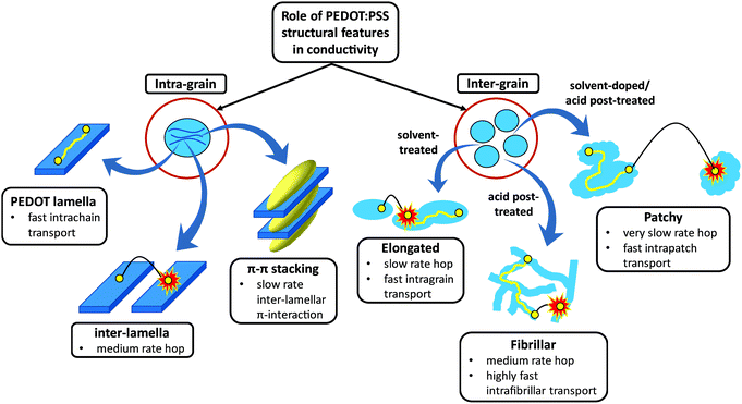 | ||
| Scheme 1 Intra- and inter-grain charge transport mechanism cartoon in semi-crystalline PEDOT:PSS films. | ||
The motivation of this study arose from an unexpected observation of PEDOT:PSS conductivity reduction upon sulfuric acid post-treatment of highly conductive solvent-doped films. To explain the underlying mechanism(s), Fourier Transform Infrared (FTIR) and Raman vibrational spectroscopy were undertaken to detect the origin of intrachain conductivity changes within each PEDOT lamella. An inclusive crystalline structure for PEDOT:PSS was proposed, using X-ray diffraction (XRD) and molecular dynamics (MD) simulation. Having identified previously-unassigned and controversial XRD peaks of PEDOT:PSS, the conductivity changes were correlated to the intra-grain structural parameters of PEDOT interchain π–π stacking and inter-lamella distances and abundance, along with changes in the inter-grain morphologies, using current-sensing atomic force microscopy (CS-AFM).
Results and discussion
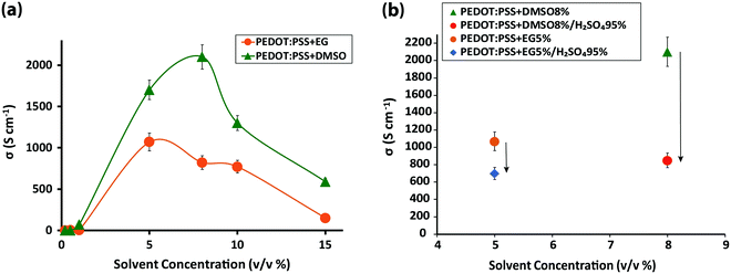
Four different samples were investigated: (1) 30 to 100 nm pristine PEDOT:PSS films, coated on glass substrates, with an average conductivity of ∼0.50 S cm−1; (2) PEDOT:PSS films immersed in sulfuric acid 95%, resulting in a thickness reduction to almost one-half due to the significant amount of PSS removal by the acid5 and an accompanying exponential increase in conductivity to ∼3200 S cm−1 (Fig. S1, ESI†); (3) PEDOT:PSS films fabricated from its aqueous dispersion doped with different concentrations of dimethyl sulfoxide (DMSO) and ethylene glycol (EG) solvents with the most conductive samples resulting from DMSO 8% and EG 5% (v/v) solvents (Fig. 1a), and (4) the highest conductivity solvent-doped PEDOT:PSS films, which surprisingly exhibited dramatic conductivity reduction upon sulfuric acid post-treatment (Fig. 1b). To explore the intrachain mode of charge transport within PEDOT:PSS grains, FTIR and Raman vibrational spectroscopy were undertaken.FTIR revealed a drastic alteration of the chemical environment around PEDOT thiophene rings induced by solvent-doping and sulfuric acid post-treatment, which disturbed the interaction between the PEDOT thiophene ring and PSS sulfonate ions (Fig. 2a) and may have caused partial desulfonation of PSS. In particular, IR peak shifts associated with PEDOT Cα–S (819, 910 and 968 cm−1), Cβ–O–C (1070, 1128 and 1181 cm−1) and Cβ–Cβ (1294 cm−1) bonds were examined. Post-treatment of PEDOT:PSS with sulfuric acid and addition of DMSO each created a new IR transmission peak near 610 cm−1 (Fig. 2b-B and C) associated with the SO42− ion bending band.17,18 Free sulfate ions could substitute some of the PSS sulfonate ions that are interacting with the PEDOT thiophene rings. Two different explanations, rooted in sulfur-containing moieties, have been offered regarding the origin of the 610 cm−1 peak: (i) dimethyl sulfate (DMS) complete hydrolysis19 and (ii) residual sulfate ions in the film even after careful rinsing of sulfuric acid with deionized water.5 However, we found the same peak for the sulfur-free EG-doped PEDOT:PSS films (Fig. S2, ESI†). We speculate that the peak belongs mainly to the sulfate ions formed after some PSS aromatic rings rupture from their sulfonic group. Both solvents form hydrogen bonds with PSS sulfonic acid (–SO3H) and sulfonate ions (–SO3−),20,21 although sulfonic acid dissociates very easily to R–SO3− and H3O+.18 Depending on the number of solvent molecules surrounding the aforementioned groups and due to the high polarity of hydrogen bonding, it is very likely that some PSS aromatic rings undergo desulfonation.22 Studies have already addressed the complex mechanism of aromatic polymer desulfonation by sulfuric acid.23–25 Desulfonation is initiated when sulfuric acid dissociates into the hydronium ion and HSO4−. The sulfonic acid (–SO3H) and sulfonate ion (–SO3−) groups are not conjugated with the benzene ring and the enhancement of the electron density at a meta-position of the benzene ring on the carbon atom from the C–S bond creates a strong, partially positive charge on the sulfur atom26 (Fig. S3a, ESI†). When the sulfuric acid is introduced, it dissociates and releases its proton, which then attacks the partially negatively charged carbon of the PSS C–S bond. The attacked carbon needs an extra electron to compensate for the new bond; thus it will grab one from the immediate neighboring carbon in the ring, resulting in carbon cation formation (Fig. S3b, ESI†). Since the benzene ring would require maintaining its aromaticity, it rearranges to form a benzene ring by releasing the weakened sulfonate group bond followed by electron delocalization throughout the ring (Fig. S3c, ESI†). The released sulfonium ion (SO3H+) will then turn into sulfuric acid in the presence of water, if any, leaving the polystyrene desulfonated. Sulfones stretch at 1340–1290 and 1165–1120 cm−1.27 Some sulfones give an additional band at 1130–1100 cm−1, and a few have a band at 1185–1175 cm−1.28 However, all these bands are masked by PEDOT strong and broad Cβ–Cβ and Cβ–O–C asymmetric stretching bands. Formation of sulfones due to the immersion of the films in sulfuric acid would disrupt the conjugation pathway29 created by the addition of DMSO or EG solutions earlier in the initial doping. Some studies have also hypothesized the occurrence of ion-exchange between the sulfate ions of the acid and the sulfonate ions of the polymer.30,31
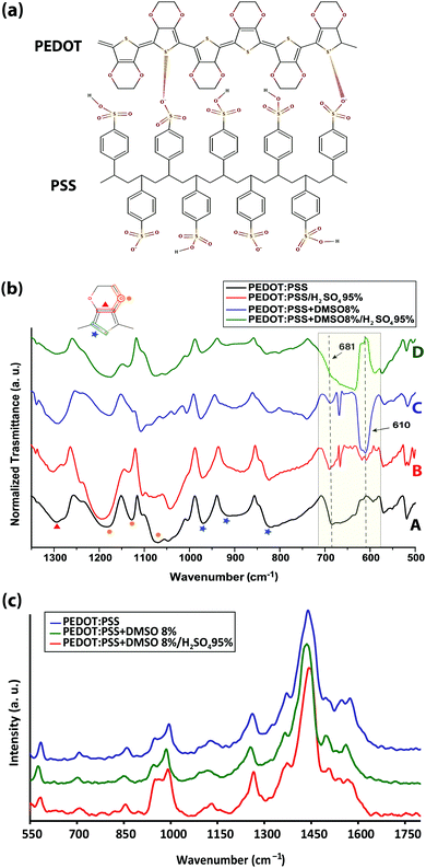 | ||
| Fig. 2 (a) Primary structure of the PEDOT:PSS complex, (b) transmission FTIR spectra of pristine, DMSO-doped, acid post-treated, and DMSO-doped/acid post-treated PEDOT:PSS thin films, and (c) Raman spectroscopy modes of pristine, DMSO-doped, and DMSO-doped/acid post-treated samples of PEDOT:PSS thin films. The peak assignments are presented in Tables S2 and S3 (ESI†). | ||
Solvent doping and/or acid post-treatment also affected the 681 cm−1 band, which has been debatably attributed to the C–S bond in PSS,32 and the C–S bond in the PEDOT thiophene ring.33,34 We propose that the peak corresponds to the PSS C–S bond since its intensity decreases after individual acid post-treatment or solvent-doping while it is fully masked by the intensity of the SO42− ion band after the sulfuric acid post-treatment of solvent-doped films. It is also interesting to see the correlation between the SO42− (610 cm−1) and PSS C–S (681 cm−1) band intensities. As the intensity of the PSS C–S band decreased upon post-treatment, the intensity of the SO42− ion band increased (shaded in Fig. 2b).
Solvent doping and/or acid post-treatment affect the interaction between PEDOT and PSS, which will be reflected in the 819, 910, and 968 cm−1 bands associated with the PEDOT thiophene ring Cα–S bond perturbations.35 For the DMSO-doped PEDOT:PSS, all the bands were blue-shifted to higher bonding energies, mainly by the enhancement of the PEDOT dipole moment triggered by the loss of ionic interaction with PSS. Remarkably, the bands were then shifted to lower frequencies after sulfuric acid post-treatment opposing the solvent contribution to the conductivity enhancement. Moreover, the intensity of the Cα–S bands contracted, suggesting that the charge carriers, polarons, and bipolarons become less delocalized, resulting in a conductivity reduction, compared with those in the solvent-doped or acid post-treated films (Fig. 2b-D).36
The impact of acid post-treatment was also seen in four more shifted peaks between 1300 and 1000 cm−1 (Fig. 2b). The peaks at 1070, 1128 and 1181 cm−1 correspond to the asymmetric stretching vibrations of the PEDOT Cβ–O–C bond,35 and the peak at 1294 cm−1 is assigned to the Cβ–Cβ bond of the ethylenedioxy segment.37 Sulfuric acid-post treatment reversed the peak shifts observed for the solvent-doped PEDOT:PSS peak compared to the undoped films (Table S1, ESI†). This can be explained by the reduction of the PEDOT dipole moment resulting from the increase of the PEDOT thiophene ring π–π stacking distance or the PEDOT morphology change from the dominant quinoid (Cβ = Cβ–Cα) form (favored structure for a linear or expanded-coil conformation) in solvent-doped films to the benzoid (Cβ–Cβ = Cα) form (preferred structure of a coil conformation). Any perturbation in the Cβ–Cβ–Cα bond impacts the vibrational frequency of Cβ–O–C bonds of the dioxy ring. An alternative explanation has also been proposed based on the possible interaction between the dipole of an organic solvent polar group, positioned in the vicinity of PEDOT, and the dipoles of PEDOT monomers within the chain as the driving force for the PEDOT conformational change.20
Raman spectroscopy (Fig. 2c, and Table S2, ESI†) also confirmed that sulfuric acid affected the PEDOT:PSS structure against any conformational change that was induced earlier by the solvents to enhance the conductivity. Solvent-doping contributed to the conductivity enhancement via inducing a change in the PEDOT resonant structure from benzoid to quinoid, observed as red shifts, and created more positive charges (holes) inside the PEDOT thiophene ring, appearing as blue shifts in the Raman spectra.38,39 The resistance for the inter-lamella hops is reduced when the PEDOT configuration changes from a coil to a more linear crystalline structure, which increases the charge mobility both within and between PEDOT lamellae. The opposite shifts caused by sulfuric acid post-treatment reverted the structural changes partly from quinoid to benzoid and/or reduced the PEDOT thiophene rings from bipolarons to polarons, resulting in conductivity reduction within PEDOT lamellae. The new arrangement of the PEDOT configuration, initially entangled inside the PSS-rich matrix, would be reflected in the form of IR and Raman band shifts and/or the appearance of new peaks, however it would be difficult to discern the conductivity enhancement from IR measurements alone.40
To investigate the structure of PEDOT:PSS after the conductivity reduction, XRD spectroscopy was performed on the pristine films (<1 μm), which resulted in a pattern with six dominant peaks at 4.1°, 8.1°, 11.2°, 13.8°, 18.2°, and 25.5° (Fig. S4, ESI†). To date, the assignment of the PEDOT:PSS XRD peaks has been controversial due to the different structures proposed by many groups. The peaks at 8.1°, 11.2°, and 13.8° are not well-defined yet either. In spite of several simulation and experimental studies,41–44 a consensus on the PEDOT:PSS semi-crystalline morphology and peak assignment has not been reached. This could be due to the following misperceptions that we noticed through our MD-simulated configurations of PEDOT and PSS, using the Universal Force Field (Movie, ESI†), confirming other groups’ modelling results:41,42 (i) the PEDOT and PSS backbones are parallel to each other (not perpendicular45,46) in their most stable form, and (ii) the plane of PEDOT lamellae, while they are interacting, bends over the PSS chain orthogonally by making a torsion angle of ∼80.4° to minimize the thermodynamic energy in order to establish a stable ionic interaction with PSS44 (Fig. 3).
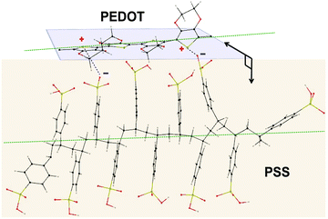 | ||
| Fig. 3 Proposed molecular dynamics simulated model for PEDOT and PSS interaction depicting their orthogonally-oriented planes and parallel backbones (green dashed lines). | ||
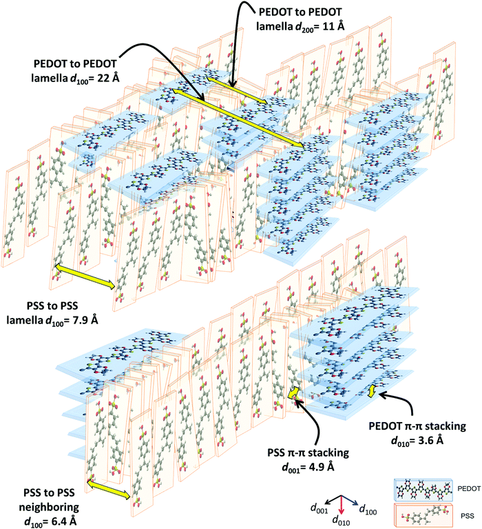
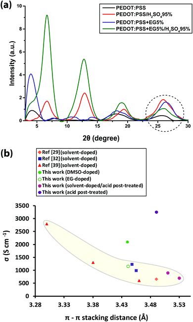
Herein, we propose a semi-crystalline model for the XRD peaks of the PEDOT:PSS structure presented in Fig. 4, taking into account the XRD-derived lattice spacing (using Bragg's law47) and MD simulation. Fig. 4 comprises π–π interacting PEDOT lamella stacks distributed along the PSS chain where only the highest and lowest PEDOT chains are pinned to the PSS SO3− ions via electrostatic interaction. The XRD spectrum of pristine PEDOT:PSS shows a peak at 4.1°, representing the 22 Å d100 spacing for the alternate inter-lamella stacking distance (denoted hereafter as dint-lam) of PEDOT to PEDOT only, and not PSS to PSS. Almost every three to four monomers of PEDOT carry a positive charge.48 Yet, due to the different length scales between the two polymers and irregular negative charges on the PSS backbone, PEDOT and PSS cannot employ a comb-teeth arrangement as considered in some studies.49 The latter arrangement can be visualized only when a fully flat planar structure of PEDOT (∼7.5 Å) and PSS (∼15.5 Å) lay beside each other to form the 23 Å distance. This may be the reason behind the proposed “alternate lamella stacking distance of PEDOT and PSS” assignment for this peak.49 However, the assignment cannot explain the equivalent peak in the following XRD pattern of sulfuric acid post-treated PEDOT:PSS films. The peak at 8.1° is the second reflection (d200) of the inter-lamella spacing of 11 Å between two side-by-side PEDOT lamellae. The weak peak at 11.2° is assigned to the d100 alternate lamella stacking distance of PSS to PSS of 7.9 Å while PEDOT planes are sandwiched in between. The proximity of this value to the ∼7.5 Å of the PEDOT width is noticeable. PSS has two peaks in its XRD diffractometry: one at around 10° and the other between 18° and 19°.50,51 The reason for the very low intensity of the 11.2° peak is probably due to the interdigitation entanglement packing of the soft PSS chains, which can be hardly captured.8 The weak peak at 13.8° corresponds to the distance of 6.4 Å between two neighboring PSS chains without any PEDOT in between. The peak at 18.2° shows the d001 spacing of PSS benzene ring π–π stacking of 4.9 Å.49 The peak arises from the rotation of PSS styrene rings toward PEDOT thiophene rings to form an ionic interaction with the lowest energy (Fig. 3 and 4). The final peak represents the d010 reflection of PEDOT thiophene ring π–π stacking (denoted hereafter as dπ–π) with a spacing distance of 3.6 Å.41 Considering our proposed model (Fig. 4), the effects of solvent-doping and acid post-treatment on PEDOT:PSS inter-grain structural changes can be tracked, using the associated XRD spectra. For the sulfuric acid post-treated films, an increase in the intensity of the PEDOT dint-lam, d200, and dπ–π peaks was observed (Fig. 5a). A large shift from 4.1° to a higher angle of 6.7° corresponds to a reduced PEDOT dint-lam of 13.2 Å (Table S3, ESI†). The planar PEDOT:PSS structure is rejected here since two planes of PEDOT lamella in dint-lam alignment could not reach a 13.2 Å distance if there was a ∼15.5 Å wide PSS layer located in between. Our proposed configuration, considering orthogonal orientation of PSS in between the PEDOT lamella stacks, is more consistent at this point. It is noteworthy that even two face-on alternate lamella stacks of PEDOT cannot come as close as 13.2 Å together with edge-on PSS layers being sandwiched in between unless sulfuric acid post-treatment has removed a significant amount of PSS, probably by desulfonation, leaving the majority of PEDOT stacks free of PSS. Hence, this structure with reduced PSS layers does not exhibit the 11.2° and 13.8° peaks. A reduction in PEDOT dint-lam was accompanied by an interlayer spacing (d200) decrease between two side-by-side PEDOT lamella stacks from 11 to 7 Å concurrently, implying that sulfuric acid brings the PEDOT lamella stacks closer to each other, making the inter-lamella charge hopping distance shorter, and hence less energy is required for the charge carriers to hop, thereby increasing the conductivity. Loss of PSS (more than 70%) after acid post-treatment was already observed by Kim et al. using a UV/vis/NIR spectrophotometer, who concluded that “the selective removal of PSS without influencing the PEDOT part” occurs.45 As a result of PSS detachment, a reduction in dπ–π between PSS benzene rings and PEDOT thiophene rings is observed as higher angle shifting of the 18.2° and 25.5° peaks, correlating with 4.69 and 3.49 Å, respectively.52 Unlike sulfuric acid post-treatment, the solvent-doped samples did not show an increase in the intensity of the PEDOT d200 peak, as a second reflection of dint-lam, in their XRD pattern. The enhancement of the PEDOT dint-lam peak intensity without any change in the d200 peak indicates that only “alternate” lamella stacks of PEDOT were crystallized abundantly upon solvent-doping. Yet, the PEDOT dint-lam and d200 peaks were shifted to lower angles, representing the expansion of the PEDOT to PEDOT inter-lamella spacing (Fig. 5a). Although the higher intensity and sharpness of the dint-lam peak suggest a change in the PEDOT structure from a coil to a more linear crystalline configuration, increasing the inter-lamella spacing would impose a greater energy burden on the charge carriers to hop. Both the alternate lamella stacking, and the adjacent lamella distances of PSS chains were increased as well. PSS and PEDOT dπ–π were both shifted to higher angles with reduced distances of 4.8 and 3.4 Å, respectively, with the latter enhancing the conductivity through a shorter distance of charge transfer.52 The sulfuric acid post-treatment of the solvent-doped samples resulted in the reversal of PEDOT dint-lam and d200 peak shifts to higher angles (Fig. 5a and Table S3, ESI†), interestingly, with their intensities even much higher than the acid post-treated films. The increased PEDOT dint-lam and d200, caused by solvent-doping, were reduced back to 13.3 and 7 Å, respectively. The two intermediate weak peaks of PSS were removed, and PSS and PEDOT dπ–π were increased to 4.7 and 3.5 Å, respectively.
The shifting of the XRD peaks for the solvent-doped/acid post-treated samples compared to those of the acid-only post-treated samples with higher intensity and sharper peaks would suggest a higher degree of crystallinity and a corresponding increase in conductivity (Fig. 5a). However, to our surprise, the conductivity was lower. To describe this anomalous behavior, the correlation between PEDOT dπ–π and conductivity was examined. The π–π electronic overlap is extremely sensitive to the local ordering of PEDOT chains.16 The interchain charge-transport is also the most resistive of the three modes of charge-transport, as pointed out earlier. Thus, small changes in PEDOT dπ–π can dramatically disturb the overall conduction. Fig. 5b shows the conductivity of pristine, solvent-doped and sulfuric acid post-treated PEDOT:PSS thin films plotted against PEDOT dπ–π in addition to the reported data from the literature. An exponential increase in conductivity with decreasing PEDOT dπ–π affirms the strong role of interchain transport in conductivity enhancement.53 Evidence suggests that the charge carrier mobility in materials like PEDOT with planar aromatic molecules is usually maximized along the direction of π–π stacking of the molecules.54 However, Fig. 5b does not take into account the PEDOT π–π stacking abundance, leading to the appearance of higher conductivity outliers, corresponding to the DMSO-doped and sulfuric acid post-treated samples.
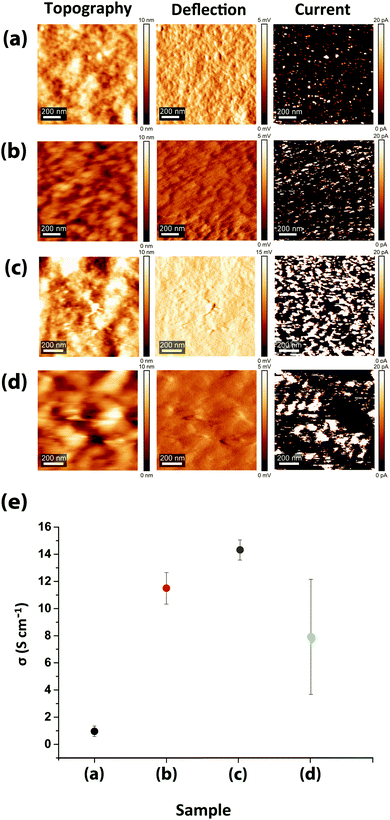
Beside the intra- and inter-grain PSS removal, the exceptionally high conductivity of PEDOT:PSS films upon sulfuric acid post-treatment compared to the solvent-doped samples is also attributed to the enhancement of intra-grain charge transport, owing to the decrease in both PEDOT dπ–π and dint-lam. Despite a much higher quantity of PEDOT lamella stackings and low PEDOT dint-lam, comparable to the highly-conductive sulfuric acid post-treated samples (13.2 Å), the conductivities of the DMSO- and EG-doped/acid post-treated samples are even lower than the solvent-doped samples (Fig. 1b and 5b). This is due to their greater PEDOT dπ–π and lower intensity (lower abundance) of PEDOT thiophene ring π–π stacking than the solvent-doped or acid-only post-treated samples, implying that although the inter-lamella charge transport resistance is decreased, concomitantly the interchain charge transport resistance is increased, resulting in a 2 to 3-fold drop in conductivity. Thus, we argue that the crystallinity and the abundance of the PEDOT lamella stacking are less influential factors for the conductivity than the dominant abundance of PEDOT thiophene ring π–π stacking and the small but significant reduction in its spacing. For such a structure, the most efficient and facile charge transfer occurs via stronger and denser π–π interactions with shorter displacement.55–57 Reducing the abundance of PEDOT π–π interactions and/or increasing the π–π stacking distance between two lamellae will bind the charge carriers to individual PEDOT chains impeding the conductivity remarkably. Following the thiophene ring π–π stacking patterns of the solvent-doped/acid post-treated PEDOT:PSS samples (Fig. S5, ESI†), it is confirmed that doping with DMSO results in higher conductivity than EG merely due to the abundance of PEDOT π–π stacking, although the latter showed more lamella stacking and their PEDOT dπ–π is the same. Our newly deduced correlation was confirmed upon examination of XRD patterns and corresponding conductivity data reported for treated PEDOT:PSS samples by numerous groups.8,52,58–63 The inter-grain conductivity, on the other hand, was under the influence of the morphology geometry (spherical, elongated, fibrillar) as well as the interconnectivity of the conducting domains. To investigate the role of the inter-grain morphology in conductivity enhancement, direct evidence of structural differences was obtained from the CS-AFM images at 20 mV bias voltage (Fig. 6a–d). An observation of the conducting domains in the current images in Fig. 6 confirms that the small coiled and separated spherical grains of the pristine PEDOT:PSS film turned into elongated and more closely-connected oval-shaped grains in the EG-doped film,1,11,20 resulting in the conductivity enhancement. Charge carriers require less energy for hopping to adjacent grains when the grains are closer or merged into each other, resulting in the well-known elongated structure. However, the interconnected network of the nanofibrillar structure of PEDOT:PSS films after sulfuric acid post-treatment45 supports their significantly higher conductivity than the solvent-doped samples. Sulfuric acid has been shown to remove the majority of PSS layers, creating a fibrillar structure that acts as a conductive network for charge carriers to transport with less energy for hopping between fibrils. Nevertheless, after the post-treatment of the solvent-doped samples with sulfuric acid, the grains formed larger patches of conductive domains but with less overall conductivity than the individual solvent-doped or sulfuric acid post-treated samples. The reason rests on the low interconnectivity of the aggregated grains, hindering the percolation of charge carriers inside the film. As the current channels in Fig. 6 show, although the size of the conducting patches is much larger than both the solvent-doped and acid post-treated samples (higher intensity of the PEDOT lamella stacking XRD peak), yet there are huge gaps (dark spots) between them, hindering the transport of charge carriers. This specifies that even if the conductivity is high within the grains, the overall conductivity could be lower owing to the weak or lack of interconnectivity between the grains. Hereby, we refer to this new type of morphology as “patchy”. The CS-AFM measurements also confirmed the trend of conductivity measured by the four-point probe method (Fig. 6e). It was expected to see a larger standard deviation for the conductivity of the EG-doped/sulfuric acid post-treated sample measured by CS-AFM. The deviation was caused by the inhomogeneous nature of the patchy morphology where in some areas the conductivity was higher than the solvent-doped films while in other spots it was closer to the pristine films.
Conclusions
In summary, the unexpected conductivity reduction of highly conductive DMSO- and EG-doped PEDOT:PSS thin films after post-treatment by sulfuric acid led to the exposure of a newly-termed “patchy” inter-grain morphology. We introduced a comprehensive semi-crystalline structural model, following the resolution of unknown and controversial XRD peaks of PEDOT:PSS. The PEDOT thiophene ring π–π stacking distance and abundance were found to play the key role in the intra-grain conductivity enhancement of this polymer. Methods that contribute to the conductivity enhancement of PEDOT:PSS require more in-depth analysis to focus further on decreasing the spacing of PEDOT interchain coupling rather than developing more lamella stacking structure in addition to creating a greater interconnected network of conducting channels. Further analysis is also required to investigate the impact of PSS detachment on the conductivity of PEDOT:PSS films.Conflicts of interest
The authors declare no competing financial interest.Acknowledgements
This study was supported in part by funding from the Canada First Research Excellence Fund (CFREF). The authors would like to express their appreciation to Prof. Uttandaraman (U. T.) Sundararaj for the four-point probe measurements.Notes and references
- J. Ouyang, C. Chu, F. Chen, Q. Xu and Y. Yang, Adv. Funct. Mater., 2005, 15, 203 CrossRef CAS.
- M. Vosgueritchian, D. Lipomi and Z. Bao, Adv. Funct. Mater., 2011, 22, 421 CrossRef.
- A. Nardes, R. Janssen and M. Kemerink, Adv. Funct. Mater., 2008, 18, 865 CrossRef CAS.
- E. Jin Bae, Y. Hun Kang, K. Jang and S. Yun Cho, Sci. Rep., 2016, 6, 18805 CrossRef PubMed.
- Y. Xia, K. Sun and J. Ouyang, Adv. Mater., 2012, 24, 2436 CrossRef CAS PubMed.
- D. A. Mengistie, M. A. Ibrahem, P. C. Wang and C. W. Chu, ACS Appl. Mater. Interfaces, 2014, 6, 2292 CrossRef CAS PubMed.
- J. Zhou, D. Anjum, L. Chen, X. Xu, I. Ventura, L. Jiang and G. Lubineau, J. Mater. Chem. C, 2014, 2, 9903 RSC.
- T. Takano, H. Masunaga, A. Fujiwara, H. Okuzaki and T. Sasaki, Macromolecules, 2012, 45, 3859 CrossRef CAS.
- U. Lang, E. Müller, N. Naujoks and J. Dual, Adv. Funct. Mater., 2009, 19, 1215 CrossRef CAS.
- Q. Wei, M. Mukaida, Y. Naitoh and T. Ishida, Adv. Mater., 2013, 25, 2831 CrossRef CAS PubMed.
- T. Chou, S. Chen, Y. Chiang, Y. Lin and C. Chao, J. Mater. Chem. C, 2015, 3, 3760 RSC.
- M. Leaf and M. Muthukumar, Macromolecules, 2016, 49, 4286 CrossRef CAS.
- Y. Kim, C. Sachse, M. Machala, C. May, L. Müller-Meskamp and K. Leo, Adv. Funct. Mater., 2011, 21, 1076 CrossRef CAS.
- Y. Xia, K. Sun and J. Ouyang, Energy Environ. Sci., 2012, 5, 5325 RSC.
- C. Greco, A. Melnyk, K. Kremer, D. Andrienko and K. Daoulas, Macromolecules, 2019, 52, 968 CrossRef PubMed.
- H. Martens, H. Brom and R. Menon, Phys. Rev. B: Condens. Matter Mater. Phys., 2001, 64, 201102 CrossRef.
- K. Nakamoto, Infrared and Raman Spectra of Inorganic and Coordination Compounds (Part B: Applications in Coordination, Organometallic, and Bioinorganic Chemistry), John Wiley & Sons, New York, 1997, vol. 1B Search PubMed.
- N. B. Colthup, L. H. Daly and S. E. Wiberley, Introduction to Infrared and Raman Spectroscopy, Academic Press, Waltham, 1990 Search PubMed.
- M. Reyes-Reyes, I. Cruz-Cruz and R. López-Sandoval, J. Phys. Chem. C, 2010, 114, 20220 CrossRef CAS.
- J. Ouyang, Q. Xu, C. Chu, Y. Yang, G. Li and J. Shinar, Polymer, 2004, 45, 8443 CrossRef CAS.
- D. A. Mengistie, P. Wang and C. Chu, J. Mater. Chem. A, 2013, 1, 9907 RSC.
- B. Friedel, P. E. Keivanidis, T. J. K. Brenner, A. Abrusci, C. R. McNeill, R. H. Friend and N. C. Greenham, Macromolecules, 2009, 42, 6741 CrossRef CAS.
- V. A. Kozlov, S. N. Ivanov and O. I. Koifman, J. Phys. Org. Chem., 2017, 30, e3715 CrossRef.
- A. C. M. Wanders and H. Cerfontain, Recl. Trav. Chim. Pays-Bas, 1967, 86, 1199 CrossRef CAS.
- G. Baddeley, G. Holt and J. Kenner, Nature, 1944, 154, 361 CrossRef CAS.
- F. Kucera and J. Jancar, Polym. Eng. Sci., 1998, 38, 783 CrossRef CAS.
- A. Elschner, Sol. Energy Mater. Sol. Cells, 2011, 95, 1333 CrossRef CAS.
- E. Robinson, Can. J. Chem., 1961, 39, 247 CrossRef CAS.
- U. Barsch and F. Beck, Electrochim. Acta, 1996, 41, 1761 CrossRef CAS.
- T. Raudsepp, M. Marandi, T. Tamm, V. Sammelselg and J. Tamm, Electrochim. Acta, 2014, 122, 79 CrossRef CAS.
- U. Johanson, M. Marandi, T. Tamm and J. Tamm, Electrochim. Acta, 2005, 50, 1523 CrossRef CAS.
- G. Neelgund, E. Hrehorova, M. Joyce and V. Bliznyuk, Polym. Int., 2008, 57, 1083 CrossRef CAS.
- J. Lee and W. Choi, J. Electrochem. Soc., 2015, 162, A935 CrossRef CAS.
- A. Österholm, T. Lindfors, J. Kauppila, P. Damlin and C. Kvarnström, Electrochim. Acta, 2012, 83, 463 CrossRef.
- Y. Liu, D. Sun, S. Askari, J. Patel, M. Macias-Montero, S. Mitra, R. Zhang, W. Lin, D. Mariotti and P. Maguire, Sci. Rep., 2015, 5, 15765 CrossRef PubMed.
- J. Ouyang, ACS Appl. Mater. Interfaces, 2013, 5, 13082 CrossRef CAS PubMed.
- Y. Lee, G. Choi, S. Lim, J. Cho, I. Choi, K. Nam and Y. Joo, Sci. Rep., 2016, 6, 25332 CrossRef PubMed.
- S. Lee, H. Park, S. Kim, W. Son, I. Cheong and J. Kim, J. Mater. Chem. A, 2014, 2, 7288 RSC.
- T. Chou, S. Chen, Y. Chiang, T. Chang, C. Lin and C. Chao, Org. Electron., 2017, 48, 223 CrossRef CAS.
- S. A. Rutledge and A. S. Helmy, ACS Appl. Mater. Interfaces, 2015, 7, 3940 CrossRef CAS PubMed.
- K. Aasmundtveit, E. Samuelsen, O. Inganäs, L. Pettersson, T. Johansson and S. Ferrer, Synth. Met., 2000, 113, 93 CrossRef CAS.
- E. Kim and J. Brédas, J. Am. Chem. Soc., 2008, 130, 16880 CrossRef CAS PubMed.
- R. Brooke, J. Franco-Gonzalez, K. Wijeratne, E. Pavlopoulou, D. Galliani, X. Liu, R. Valiollahi, I. Zozoulenko and X. Crispin, J. Mater. Chem. A, 2018, 6, 21304 RSC.
- E. Yildirim, G. Wu, X. Yong, T. Tan, Q. Zhu, J. Xu, J. Ouyang, J. Wang and S. Yang, J. Mater. Chem. C, 2018, 6, 5122 RSC.
- N. Kim, S. Kee, S. Lee, B. Lee, Y. Kahng, Y. Jo, B. Kim and K. Lee, Adv. Mater., 2014, 26, 2268 CrossRef CAS PubMed.
- X. Wang, A. Kyaw, C. Yin, F. Wang, Q. Zhu, T. Tang, P. Yee and J. Xu, RSC Adv., 2018, 8, 18334 RSC.
- B. D. Cullity, Elements of X-Ray Diffraction, Addison-Wesley Publishing Company, London, 1978 Search PubMed.
- A. Elschner, S. Kirchmeyer, W. Lövenich, U. Merker and K. Reuter, PEDOT: Principles and Applications of an Intrinsically Conductive Polymer, CRC Press, Boca Raton, 2011 Search PubMed.
- N. Kim, B. Lee, D. Choi, G. Kim, H. Kim, J. Kim, J. Lee, Y. Kahng and K. Lee, Phys. Rev. Lett., 2012, 109, 106405 CrossRef PubMed.
- Z. Xu, Y. Gao, T. Liu, L. Wang, S. Bian and J. Lin, J. Mater. Chem., 2012, 22, 21695 RSC.
- Z. Matusinovic, R. Shukla, E. Manias, C. Hogshead and C. Wilkie, Polym. Degrad. Stab., 2012, 97, 2481 CrossRef CAS.
- C. Palumbiny, F. Liu, T. Russell, A. Hexemer, C. Wang and P. Müller-Buschbaum, Adv. Mater., 2015, 27, 3391 CrossRef CAS PubMed.
- M. Carini, M. Ruiz, I. Usabiaga, J. Fernández, E. Cocinero, M. Melle-Franco, I. Diez-Perez and A. Mateo-Alonso, Nat. Commun., 2017, 8, 15195 CrossRef CAS PubMed.
- Y. Che, A. Datar, X. Yang, T. Naddo, J. Zhao and L. Zang, J. Am. Chem. Soc., 2007, 129, 6354 CrossRef CAS PubMed.
- Z. Yao, J. Wang and J. Pei, Cryst. Growth Des., 2018, 18, 7 CrossRef CAS.
- A. Ugur, F. Katmis, M. Li, L. Wu, Y. Zhu, K. Varanasi and K. Gleason, Adv. Mater., 2015, 27, 4604 CrossRef CAS PubMed.
- J. Rivnay, S. Inal, B. Collins, M. Sessolo, E. Stavrinidou, X. Strakosas, C. Tassone, D. Delongchamp and G. Malliaras, Nat. Commun., 2016, 7, 11287 CrossRef PubMed.
- L. Ouyang, C. Musumeci, M. Jafari, T. Ederth and O. Inganäs, ACS Appl. Mater. Interfaces, 2015, 7, 19764 CrossRef CAS PubMed.
- S. Kim, C. Kim, Y. Kim, N. Kim, W. Lee, E. Lee, D. Kim, S. Park, K. Lee, J. Rivnay and M. Yoon, Nat. Commun., 2018, 9, 3858 CrossRef PubMed.
- N. Ikeda, T. Koganezawa, D. Kajiya and K. I. Saitow, J. Phys. Chem. C, 2016, 120, 19043 CrossRef CAS.
- J. Zhou, E. Li, R. Li, X. Xu, I. Ventura, A. Moussawi, D. Anjum, M. Hedhili, D. Smilgies, G. Lubineau and S. Thoroddsen, J. Mater. Chem. C, 2015, 3, 2528 RSC.
- H. Yano, K. Kudo, K. Marumo and H. Okuzaki, Sci. Adv., 2019, 5, eaav9492 CrossRef PubMed.
- H. Sirringhaus, P. Brown, R. Friend, M. Nielsen, K. Bechgaard, B. Langeveld-Voss, A. Spiering, R. Janssen, E. Meijer, P. Herwig and D. de Leeuw, Nature, 1999, 401, 685 CrossRef CAS.
Footnote |
| † Electronic supplementary information (ESI) available. See DOI: 10.1039/c9tc06311k |
| This journal is © The Royal Society of Chemistry 2020 |

