Intrinsic and extrinsic proton conductivity in metal-organic frameworks†
S. Tominaka*ab and
A. K. Cheetham*a
aDepartment of Materials Science and Metallurgy, University of Cambridge, Charles Babbage Road, Cambridge CB3 0FS, UK. E-mail: akc30@cam.ac.uk; Fax: +44 (0)1223 334567; Tel: +44 (0)1223 767061
bInternational Center for Materials Nanoarchitectonics (WPI-MANA), National Institute for Materials Science (NIMS), Ibaraki 305-0044, Japan. E-mail: TOMINAKA.Satoshi@nims.go.jp; Tel: +81 (0)29 860 4594
First published on 16th October 2014
Abstract
Metal-organic frameworks (MOFs), a new class of solid-state materials, have recently been investigated as proton conductors, but little is known about their mechanisms. Since most of the conductivities reported so far were measured using powder samples, there is uncertainty as to whether they exhibit intrinsic proton transport through frameworks and/or micropores, or extrinsic transport through interparticle phases. Herein, we re-visit ferrous oxalate dihydrate [Fe(ox)(H2O)2] (ox = oxalate anion), which is a dense MOF and recognized as a model system for MOF-based proton conductors. By single-crystal measurements using microelectrodes, we show that protons do not transport through the crystals (<10−9 S cm−1), but that the conductivity observed in powder samples originates from interparticle phases. This result raises a question as to how general is this phenomenon? We have comprehensively surveyed the literature on solid-state proton conductors and found that large numbers of MOFs, including [Fe(ox)(H2O)2], have a similar activation energy to those of gels and interparticle conductors in classical solid-state materials. This indicates a considerable contribution from interparticle phases towards proton conductivity in MOFs, and single crystal analysis or special methods for powder analysis are clearly necessary to confirm intrinsic conductivity.
Solid-state ion conductors are of great importance for the development of fuel cells, batteries and supercapacitors.1 A variety of solid-state materials, such as polymers, inorganic materials, and, recently, metal-organic frameworks (MOFs), have been explored for this application. MOFs are a new class of solid-state materials, comprising metal ions and organic ligands that are linked to form one-dimensional to three-dimensional structures.2,3 Porous MOFs have attracted considerable attention in view of their potential applications in gas sorption, carbon dioxide trapping and catalysis.2 Since the pores can trap proton carrier molecules as well as accommodating modifications of the walls, these porous MOFs have also been investigated as proton conductors,4–6 especially for anhydrous conduction.7,8 Dense MOFs,9 which do not have pores that can trap proton carriers, are more analogous to the classical inorganic proton conductors, and protons are expected to be transported through the crystal lattice via defects.
The most extensively studied polymer electrolyte, Nafion, was invented more than 50 years ago, but its proton conduction mechanism is still unclear, mainly due to its complicated ionic channel structure.10,11 Compared with that situation, the mechanism in MOFs should be more straightforward, because their detailed crystal structures can be determined by diffraction methods. However, even though a number of proton conductive MOFs have been reported, they need further experimental and theoretical analysis in order to establish a better understanding of their conduction mechanisms. In particular, single-crystal conductivity measurements are necessary to clarify whether protons are transported through the lattice and/or micropores or through interparticle phases. Such interparticle conduction is often observed in inorganic proton conductors and can show conductivities of >10−3 S cm−1 at room temperature (RT).12 Thus, it is reasonable to consider whether it contributes to, or even dominates, proton conduction in some of the MOFs.
In the present work we revisit a well-known, proton conductive dense MOF: ferrous oxalate dihydrate [Fe(ox)(H2O)2] (ox = oxalate anion). This dense MOF shows an excellent conductivity of 1.3 × 10⁻³ S cm−1 (at 25 °C and 98% relative humidity (RH)),13 and is regarded as an outstanding example of MOF-based proton conductors.4 However, it is unclear whether protons are transported through the framework or not because the data were obtained from a polycrystalline pellet.13 Here we investigate the conductivity of [Fe(ox)(H2O)2] by single crystal methods using microelectrodes,14 in order to acquire a better understanding of MOF-based proton conductors and this system in particular.
Results and discussion
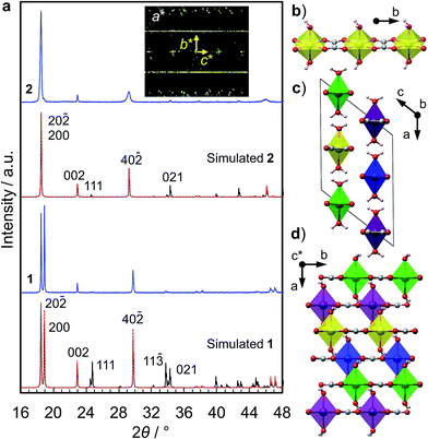
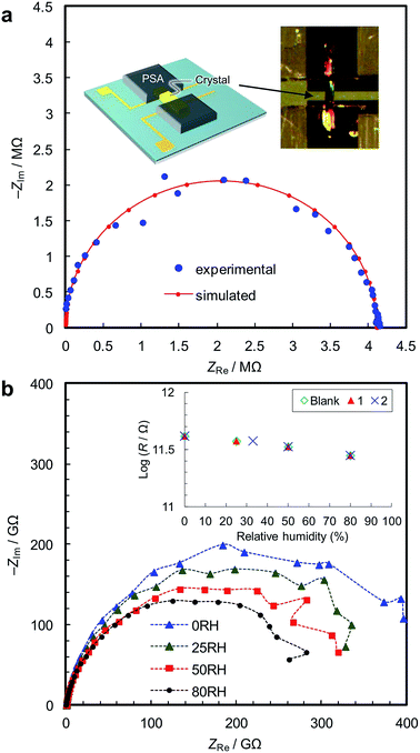
We synthesized two types of [Fe(ox)(H2O)2] crystals; one comprises high quality single-crystalline prisms (1) while the other comprises prisms with a significant level of stacking faults (2) (which is typical for [Fe(ox)(H2O)2]).15,16 1 was synthesized by annealing out the stacking faults in 2 at 90 °C. The crystal structures were determined by single crystal X-ray diffraction, and phase purity was confirmed by powder diffraction (Fig. 1a). Both have [Fe(ox)(H2O)2] chains along the long axis of the prisms (i.e., along the b axis, determined by diffraction, Fig. 1b), though 2 has stacking faults along the c* axis according to the streaks observed in the reciprocal lattice (inset in Fig. 1a, and S1†). The different domains are shifted by 50% along the a or b axes (Fig. 1c and d, and S2†). The unit cell is similar in both cases, except for a 1.2% expansion of the a axis in 2; 1 [a = 12.065 (12) Å, b = 5.559 (2) Å, c = 9.817(9) Å, β = 128.03 (15)° at 293 K] and 2 [a = 12.209 (4) Å, b = 5.5526 (7) Å, c = 9.865 (3) Å, β = 128.20 (6)° at 297 K]. Compared with the reported data [a = 12.011(11) Å, b = 5.557(5) Å, c = 9.920(9) Å, β = 128.53(3)° at 293 K],16 1 has a 0.4% longer a axis and a 1.0% shorter c axis (Table S1†). These differences are attributable to the low quality of the single crystal data of 1 due to twinning; the lattice constants obtained by Pawley fitting of the powder X-ray data agree well with the reported values (Fig. S3 and Table S1†).Fig. 2a shows the single-crystal impedance set-up and demonstrates its performance for an electrically conductive tetrathiafulvalene nitrate crystal (Fig. S4†).14 A tiny deep red crystal was placed on two gold microelectrodes having a 80 μm gap (Fig. 2a, inset), and a semicircle, whose diameter can be assigned to resistance of the material (1.1 kΩ cm), was obtained. This confirms the reliability of the conductivity measurements using the microelectrode method. Fig. 2b shows impedance spectra of 1, measured along the b axis of the crystal, i.e., along the [Fe(ox)(H2O)2] chains. The resistance is >1011 Ω, and slightly decreases with increasing humidity. As shown in the inset, 1, 2 and the blank cell have almost the same resistance, indicating that the conductivity originates from the quartz surface, not from [Fe(ox)(H2O)2]. In addition, the spectra of 1, 2 and the blank cell are similar (Fig. S5†), confirming that the large resistances are attributable to the bulk of the materials, not to the contact between the materials and the electrodes. The proton conductivity through the [Fe(ox)(H2O)2] framework is judged to be ≪5.4 × 10⁻⁹ S cm−1 (20 °C, 80%RH) for 1. In other words, it is an insulator. The discussion on the hydrogen bond networks also supports the conclusion (Fig. S6†).
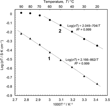
We then carried out conductivity measurements of 1 and 2 using powder samples under saturated water vapour (Fig. S7–S9†). The conductivity values are 5.7 × 10⁻⁴ S cm−1 for 1 and 1.5 × 10⁻³ S cm−1 for 2 at 20 °C (dry samples, <10−12 S cm−1); these are in good agreement with the previous measurements.16 The Arrhenius plots (Fig. 3) show that proton conduction of 1 proceeds via a constant mechanism in the range 20–90 °C, as indicated by the linear relationship (activation energy, Ea = 0.17 eV, and pre-exponential factor, σ0 = 1.5 × 10² S cm−1 K−1). 2 has similar kinetics in the range 20–60 °C (Ea = 0.14 eV and σ0 = 1.2 × 10² S cm−1 K−1), but the gradient decreases at higher temperatures, indicating that some change has taken place. This is most likely due to the annealing out of the stacking faults which takes place in this temperature range. The Ea values are close to those for proton conduction in liquids,17 Ea = ∼0.1 eV.18 In our opinion, therefore, the protons are transported through an aqueous phase that is formed between the particles. Since the solubility of [Fe(ox)(H2O)2] is negligible (ESI†), the protons must be released from the particle surface. This is consistent with the Gouy-Chapman Theory of diffuse layers,19 which shows that protons can exist as far away as ∼900 nm from fixed counter anions.20
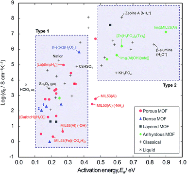
In order to explore the generality of interparticle conduction, we have surveyed the literature on proton conductors more widely. Fig. 4 compares σ0 vs. Ea for proton conductivity in MOFs in comparison with classical solid-state materials (details are available in the ESI; Table S2–S4 and Fig. S10†). We can classify them into two types on the basis of their activation energies: type 1 has Ea < 0.4 eV, and type 2 has Ea > 0.5 eV. In classical solid-state materials, most of the gels, polymer electrolytes and interparticle conductors are type 1, while most of anhydrous or microporous conductors are type 2. The exception is the anhydrous conductor, CsHSO4, which has significant rotational disorder of SO4, and thus protons can move as in a liquid.21
From the extensive studies of classical hydrated proton conductors, such as Nafion, we can establish some fundamental aspects of proton conduction in hydrated MOFs. Nafion has 18–35 Å water nanochannels (11 wt% H2O) lined by –SO3H groups at separations of ∼8 Å.10,22 With dehydration, the channel becomes narrower (<10 Å), and Ea increases up to 0.4–0.5 eV due to the influence of the walls.17 This high Ea can be accounted for by the restriction of the molecular dynamics in nanopores, because the diffusion of molecules in nanopores becomes slower than in the bulk when the pores are smaller than about ten molecular diameters;23 furthermore, the Grotthuss Mechanism does not operate due to the lack of a long-range hydrogen bonded network.24 Such influence of the walls is also observed in microporous materials; for example, zeolite-A (∼4.5 Å aperture) containing NH4+ (2.8 Å diameter) with 11 wt% water shows Ea = 0.63 eV.25
Compared with these classical materials, the porous MOFs of type 1 have exceptionally low Ea values as if there is no influence of the interior walls. For example, MIL-53 ([M(OH)(bdc)], bdc = 1,4-benzenedicarboxylate anion) has 8.5 Å × 8.5 Å channels,8,26 and MIL-53 functionalized with –CO2H groups shows Ea = 0.21 eV.6 [Ca(btcH)(H2O)]·H2O (btc = 1,3,5-benzenetricarboxylate anion) has <6.4 Å water channels,27,28 and shows Ea = 0.18 eV.29 [La(dtmpH5)]·7H2O (dtmp = hexamethylenediamine tetramethylenephosphonate anion) has water channels of <11.7 Å,28 and shows Ea = 0.28 eV.30 These low Ea values in microporous MOF materials probably indicates the presence of interparticle conduction as found in the case of polycrystalline [Fe(ox)(H2O)2]. Thus, we would argue that the observed conductivities are probably extrinsic rather than intrinsic.
By contrast, most of the anhydrous porous MOFs containing heterocycles (i.e., imidazole and triazole) as guest carriers are in type 2. For example, MIL-53 containing guest imidazole molecules (4.3 Å × 3.7 Å) has Ea of 0.9 eV8 (while free imidazole and imidazole in polymer electrolytes have a lower Ea of 0.25 eV).31 We speculate that the high Ea of the former points to some influence from pore walls and thus the conductivities of these anhydrous MOFs are probably due to intrinsic mobility through the micropores. Another example of an intrinsic conductor is the anhydrous, dense MOF, [Zr(HPO4)2(Tz)2] (Tz = 1,2,4-triazole), whose conductivity was the same for both single crystal and powder samples.32 In the light of the present work, we regard this material as an analogue of KH2PO4 and the high Ea is probably due to the unsuitable hydrogen bond lengths.33
In order to be certain of obtaining reliable data, we propose that one should measure the conductivity using single crystal samples. Whenever powder samples are used, it is hard to remove the influence of interparticle phases, especially in hydrated conductors. In addition, there is further concern about the reliability with powders due to the possibility of phase transitions associated with the pelletizing pressure. The impact of the pelletizing process is often underestimated, but can be very important in yielding reproducible results.34 The pressure needed for making a stable pellet form of a MOF, e.g., 0.2–0.5 GPa in our own experience, might be too high for some MOFs to retain the original structure of interest. For example, MIL-53(Cr) undergoes a phase transition at around 55 MPa,35 zinc imidazolate undergoes phase transition in the range 0.54–0.85 GPa,36 [Zn4O(14bdc)3] (MOF-5) is amorphized at 3.5 MPa,37 and an erbium formate framework undergoes a phase transition at 0.6 GPa.38 It is better not to pelletize porous MOFs but to prepare the sample using milder methods, as was done for Im@MIL53;8 PXRD patterns should also be checked after the measurements. We confirmed that 0.5 GPa does not change the crystal structure of the dense framework of [Fe(ox)(H2O)2]. We believe that the difference between our powder results and the previously reported ones (Ea = 0.37 eV and σ0 = 106 S cm−1 K−1 at 98%RH)13 is due to the pelletization procedure or the RH difference.
Conclusions
On the basis of experimental evidence and a literature survey, it is proposed that hydrated interparticle phases make a considerable contribution to proton conduction in many MOFs when measurements are made on pellets. MOFs are quite new materials in terms of the history of proton conductors, and the next stage in this area is to acquire a better understanding of proton conduction mechanisms in such systems.Methods
Synthesis
Diethyl oxalate (1 mmol; Aldrich, >99%) and iron sulfate heptahydrate (2 mmol; Aldrich, >99%) were dissolved in 20 mL of distilled water.16 The solution was heated by microwave radiation (Biotage Initiator) at 90 °C for 2 h, slowly cooled down to room temperate, and then aged overnight. These crystals, 2 (yield = 72%, oxalate-base), were further treated in the mother solution at 90 °C for 3 days, 1 (yield = 82%). Yellow prisms (10–100 μm thick and 100–1000 μm long) were recovered by vacuum filtration and rinsed with distilled water.The chemical compositions were determined by elemental analysis at the Department of Chemistry, University of Cambridge (found, calcd), for C2H4O6Fe:C (13.31, 13.35), H (2.20, 2.22), N (0.00, 0.00) for 1; C (13.34, 13.35), H (2.12, 2.22), N (0.00, 0.00) for 2. The H2O content was determined by thermal analysis (Fig. S11†) (found, calcd): 1 (21.4, 20.0), 2 (20.4, 20.0).
Structure determinations
The crystal structures were determined at room temperature by single crystal diffractometry using an Oxford Diffraction Gemini A Ultra X-ray diffractometer with Mo Kα radiation. The structure was solved by direct methods and then refined by the least squares methods using the SHELX program39 within the Olex2 interface.40 All non-hydrogen atoms were refined anisotropically and hydrogen atoms were refined isotropically. Hydrogen atoms on water molecules were then added to calculated positions. Visualization of structures was carried out using the VESTA program.41 CIF files are available (CCDC 1010845-1010846).The phase purity was confirmed by powder X-ray diffraction (PXRD). The PXRD data were collected using a Bruker-AXS D8 diffractometer with Cu Kα radiation in the Bragg–Brentano geometry. The patterns were analyzed by the Pawley method using the GSAS-II software,42 and plotted with zero-shift correction and background subtraction. The PXRD patterns were simulated using the Mercury program43 with the March-Dollase parameter44 of 3.0 for modeling the influence of preferred orientation. For the simulations, the high quality crystallographic structure reported by Echigo et al. was used for 1,16 and the crystallographic information obtained by single crystal diffraction in the present work was used for 2.
Single-crystal impedance measurements
The single-crystal impedance measurements are carried out by mounting the crystal on a quartz chip having microelectrodes with a 80 μm gap (Fig. 2a, inset).14 Humidity was controlled by mixing water-saturated nitrogen gas and dry nitrogen gas, and AC impedance spectra were collected after an equilibration time of >6 h. The conductivity was measured by the AC impedance method using a Gamry Interface1000 electrochemical instrument in the frequency range of 1 MHz to 10 mHz at an AC amplitude of 100 mV. The crystallographic orientations of the samples were checked using the single-crystal diffractometer.Powder impedance measurements
The crystals (100–130 mg) were gently ground using a pestle and mortar, and then pelletized (1 cm ϕ, ∼0.6 mm thick) at 0.5 GPa for 5 min with a few drops of water. The data were collected by keeping the pellets in a closed cell containing saturated water vapour. After equilibration at 90 °C for a few days, impedance spectra were collected at every 10 °C from 90 °C to 20 °C with an equilibration time of >8 h. The reproducibility was confirmed using different pellets prepared in the same way.Infrared spectroscopy
Fourier-transform infrared spectroscopy (FTIR) was carried out using a Bruker Tensor 27 infrared spectrometer with a diamond attenuated total reflectance (ATR) attachment. The data were collected in the wavenumber range from 520 to 4000 cm−1 at room temperatureAcknowledgements
This work was supported by an Advanced Investigator Award to AKC from the European Research Council (ERC) and by the World Premier International Research Center Initiative on “Materials Nanoarchitectonics (WPI-MANA)” from MEXT, Japan.Notes and references
- Solid State Electrochemistry, ed. P. G. Bruce, Cambridge University Press, Cambridge, 1995 Search PubMed.
- H. Furukawa, K. E. Cordova, M. O'Keeffe and O. M. Yaghi, Science, 2013, 341, 974 CrossRef CAS PubMed.
- A. K. Cheetham, C. N. R. Rao and R. K. Feller, Chem. Commun., 2006, 4780–4795 RSC; M. Eddaoudi, J. Kim, N. Rosi, D. Vodak, J. Wachter, M. OÕKeeffe and O. M. Yaghi, Science, 2002, 295, 469–472 CrossRef CAS PubMed.
- M. Yoon, K. Suh, S. Natarajan and K. Kim, Angew. Chem., Int. Ed., 2013, 52, 2688–2700 CrossRef CAS PubMed.
- P. Ramaswamy, N. E. Wong and G. K. H. Shimizu, Chem. Soc. Rev., 2014, 43, 5913–5932 RSC.
- A. Shigematsu, T. Yamada and H. Kitagawa, J. Am. Chem. Soc., 2011, 133, 2034–2036 CrossRef CAS PubMed.
- J. A. Hurd, R. Vaidhyanathan, V. Thangadurai, C. I. Ratcliffe, I. L. Moudrakovski and G. K. H. Shimizu, Nat. Chem., 2009, 1, 705–710 CrossRef CAS PubMed.
- S. Bureekaew, S. Horike, M. Higuchi, M. Mizuno, T. Kawamura, D. Tanaka, N. Yanai and S. Kitagawa, Nat. Mater., 2009, 8, 831–836 CrossRef CAS PubMed.
- A. K. Cheetham and C. N. R. Rao, Science, 2007, 318, 58–59 CrossRef CAS PubMed.
- K. Schmidt-Rohr and Q. Chen, Nat. Mater., 2008, 7, 75–83 CrossRef CAS PubMed.
- K. A. Mauritz and R. B. Moore, Chem. Rev., 2004, 104, 4535–4585 CrossRef CAS.
- G. Alberti and M. Casciola, in Proton conductors: Solids, membranes and gels (materials and devices), ed. P. Colomban, Cambridge University Press, Cambridge, 1992, pp. 238–253 CrossRef CAS PubMed; S. Tominaka, N. Akiyama, F. Croce, T. Momma, B. Scrosati and T. Osaka, J. Power Sources, 2008, 185, 656–663 CrossRef CAS PubMed; P. Colomban and A. Novak, in Proton conductors: Solids, membranes and gels (materials and devices), ed. P. Colomban, Cambridge University Press, Cambridge, 1992, pp. 272–293 Search PubMed.
- T. Yamada, M. Sadakiyo and H. Kitagawa, J. Am. Chem. Soc., 2009, 131, 3144–3145 CrossRef CAS PubMed.
- S. Tominaka, S. Henke and A. K. Cheetham, CrystEngComm, 2013, 15, 9400–9407 RSC.
- J. Dubernat and H. Pezerat, J. Appl. Crystallogr., 1974, 7, 387–393 CrossRef CAS.
- T. Echigo and M. Kimata, Phys. Chem. Miner., 2008, 35, 467–475 CrossRef CAS PubMed.
- M. Eikerling and A. A. Kornyshev, J. Electroanal. Chem., 2001, 502, 1–14 CrossRef CAS.
- P. Colomban and A. Novak, in Proton conductors: Solids, membranes and gels (materials and devices), ed. P. Colomban, Cambridge University Press, Cambridge, 1992, pp. 38–60 Search PubMed.
- A. J. Bard and L. R. Faulkner, in Electrochemical methods: fundamentals and applications, John Wiley & Sons, Inc, New York, 2001, pp. 534–554 Search PubMed.
- S. Tominaka, C.-W. Wu, K. Kuroda and T. Osaka, J. Power Sources, 2010, 195, 2236–2240 CrossRef CAS PubMed.
- P. Colomban and A. Novak, in Proton Conductors: Solids, Membranes and Gels - Materials and Devices, ed. P. Colomban, Cambridge University Press, Cambridge, 1992, pp. 165–182 Search PubMed.
- S. J. Paddison and R. Paul, Phys. Chem. Chem. Phys., 2002, 4, 1158–1163 RSC.
- S. T. Cui, J. Chem. Phys., 2005, 123, 054706 CrossRef CAS PubMed.
- K. D. Kreuer, A. Rabenau and W. Weppner, Angew. Chem., Int. Ed., 1982, 21, 208–209 CrossRef.
- K. D. Kreuer, W. Weppner and A. Rabenau, Mater. Res. Bull., 1982, 17, 501–509 CrossRef CAS.
- G. Férey, Chem. Soc. Rev., 2008, 37, 191–214 RSC; C. Serre, F. Millange, C. Thouvenot, M. Nogues, G. Marsolier, D. Louer and G. Férey, J. Am. Chem. Soc., 2002, 124, 13519–13526 CrossRef CAS PubMed.
- M. J. Plater, R. A. Howie and A. J. Roberts, Chem. Commun., 1997, 1151 Search PubMed; A. L. Spek, Acta Crystallogr., Sect. D: Biol. Crystallogr., 2009, 65, 148–155 CrossRef CAS PubMed.
- Calculated using the Platon software.
- A. Mallick, T. Kundu and R. Banerjee, Chem. Commun., 2012, 48, 8829–8831 RSC.
- R. M. P. Colodrero, P. Olivera-Pastor, E. R. Losilla, M. A. G. Aranda, L. Leon-Reina, M. Papadaki, A. C. McKinlay, R. E. Morris, K. D. Demadis and A. Cabeza, Dalton Trans., 2012, 41, 4045–4051 RSC.
- K. D. Kreuer, A. Fuchs, M. Ise, M. Spaeth and J. Maier, Electrochim. Acta, 1998, 43, 1281–1288 CrossRef CAS.
- D. Umeyama, S. Horike, M. Inukai, T. Itakura and S. Kitagawa, J. Am. Chem. Soc., 2012, 134, 12780–12785 CrossRef CAS PubMed.
- A. Potier, in Proton conductors: Solids, membranes and gels (materials and devices), ed. P. Colomban, Cambridge University Press, Cambridge, 1992, pp. 1–17 Search PubMed.
- P. J. Beldon, S. Tominaka, P. Singh, T. S. Dasgupta, E. G. Bithell and A. K. Cheetham, Chem. Commun., 2014, 50, 3955–3957 RSC.
- I. Beurroies, M. Boulhout, P. L. Llewellyn, B. Kuchta, G. Férey, C. Serre and R. Denoyel, Angew. Chem., Int. Ed., 2010, 49, 7526–7529 CrossRef CAS PubMed.
- E. C. Spencer, R. J. Angel, N. L. Ross, B. E. Hanson and J. A. K. Howard, J. Am. Chem. Soc., 2009, 131, 4022–4026 CrossRef CAS PubMed.
- Y. H. Hu and L. Zhang, Phys. Rev. B: Condens. Matter Mater. Phys., 2010, 81, 174103 CrossRef.
- E. C. Spencer, M. S. R. N. Kiran, W. Li, U. Ramamurty, N. L. Ross and A. K. Cheetham, Angew. Chem., Int. Ed., 2014, 53, 5689–5692 CrossRef.
- G. M. Sheldrick, Acta Crystallogr., Sect. A: Found. Crystallogr., 2008, 64, 112–122 CrossRef CAS PubMed.
- O. V. Dolomanov, L. J. Bourhis, R. J. Gildea, J. A. K. Howard and H. Puschmann, J. Appl. Crystallogr., 2009, 42, 339–341 CrossRef CAS.
- K. Momma and F. Izumi, J. Appl. Crystallogr., 2011, 44, 1272–1276 CrossRef CAS.
- B. H. Toby and R. B. Von Dreele, J. Appl. Crystallogr., 2013, 46, 544–549 CrossRef CAS.
- C. F. Macrae, I. J. Bruno, J. A. Chisholm, P. R. Edgington, P. McCabe, E. Pidcock, L. Rodriguez-Monge, R. Taylor, J. van de Streek and P. A. Wood, J. Appl. Crystallogr., 2008, 41, 466–470 CrossRef CAS.
- W. A. Dollase, J. Appl. Crystallogr., 1986, 19, 267–272 CrossRef CAS.
Footnote |
| † Electronic supplementary information (ESI) available: Experimental details, crystallographic analysis, cif files, thermogravimetric analysis, infrared spectra. CCDC 1010845–1010846 and 1020095–1020096. For ESI and crystallographic data in CIF or other electronic format see DOI: 10.1039/c4ra11472f |
| This journal is © The Royal Society of Chemistry 2014 |


