 Open Access Article
Non-flammable, dilute, and hydrous organic electrolytes for reversible Zn batteries†
Guoqiang
Ma‡
a,
Licheng
Miao‡
c,
Wentao
Yuan
a,
Kaiyue
Qiu
a,
Mengyu
Liu
a,
Xueyu
Nie
a,
Yang
Dong
b,
Ning
Zhang
 *a and
Fangyi
Cheng
 *bd
*bd
aCollege of Chemistry & Environmental Science, Key Laboratory of Analytical Science and Technology of Hebei Province, Hebei University, Baoding 071002, P. R. China. E-mail: ningzhang@hbu.edu.cn
bKey Laboratory of Advanced Energy Materials Chemistry (Ministry of Education), College of Chemistry, Nankai University, Tianjin 300071, P. R. China. E-mail: fycheng@nankai.edu.cn
cChina College of Physics and Optoelectronic Engineering, Shenzhen University, Shenzhen 518060, P. R. China
dHaihe Laboratory of Chemical Transformation, Tianjin 300071, P. R. China
First published on 27th August 2022
Abstract
Rechargeable Zn batteries hold great practicability for cost-effective sustainable energy storage but suffer from irreversibility of the Zn anode in aqueous electrolytes due to parasitic H2 evolution, corrosion, and dendrite growth. Herein, we report a non-flammable, dilute, and hydrous organic electrolyte by dissolving low-cost hydrated Zn(ClO4)2·6H2O in trimethyl phosphate (TMP), which homogenizes plating/stripping and enables in situ formation of a Zn3(PO4)2–ZnCl2-rich interphase to stabilize the Zn anode. A dilute 0.5 m Zn(ClO4)2·6H2O/TMP electrolyte featuring a H2O-poor Zn2+-solvation sheath and low water activity enables significantly enhanced Zn reversibility and a wider electrochemical window than the concentrated counterpart. In this formulated electrolyte, the Zn anode exhibits a high efficiency of 99.5% over 500 cycles, long-term cycling for 1200 h (5 mA h cm−2 at 5 mA cm−2) and stable operation at 50 °C. The results would guide the design of hydrous organic electrolytes for practical rechargeable batteries employing metallic electrode materials.
Introduction
Rechargeable Zn batteries (RZBs) are promising candidates for large-scale energy storage applications, benefiting from the advantages of Zn such as an abundant reservoir, low cost, and high theoretical specific gravimetric/volumetric capacity (820 mA h g−1 and 5855 mA h cm−3). Most RZBs employ aqueous electrolytes that feature high safety and good environmental compatibility.1–4 Nonetheless, in aqueous electrolytes, Zn metal anodes are generally plagued by severe irreversibility caused by water-induced side reactions (e.g., H2 evolution and Zn corrosion).5–8 In non-aqueous Li batteries, the formation of a stable solid electrolyte interphase (SEI) derived from the decomposition of an organic solvent and/or salt anion allows ionic transport but blocks the solvents and electrons, which is critical for the reversible cycling of metal anodes.9–11 Unfortunately, the water decomposition along with H2 evolution in aqueous electrolytes makes it difficult to form a protective SEI on Zn anodes. Instead, the elevation of local pH near the Zn surface incurs the formation of loose by-products of hydroxides/oxides, causing low Zn plating/stripping efficiency.12–15 Simultaneously, the rampant dendritic Zn growth in aqueous electrolytes would exacerbate the parasitic reactions and battery failure.16–18Effective strategies to stabilize Zn anodes include designing highly concentrated aqueous electrolytes19–23 and using aqueous–organic hybrid electrolytes.24–29 Alternatively, exploring organic electrolytes would offer another opportunity to boost Zn reversibility because of the high thermodynamic stability of Zn in organic solvents.30–33 However, nonaqueous RZBs often employ solvents of acetonitrile (AN),34,35 ethylene glycol (EG),36,37 and carbonates,38,39 which are highly flammable and pose safety hazards. Very recently, a concentrated hydrous organic electrolyte composed of 4 mol kg−1 (m) hydrated Zn(BF4)2 in EG has been proposed to tackle Zn dendrite growth and water-induced parasitic reactions.36 Compared with the aqueous counterpart, most anhydrous or hydrous organic electrolytes have lower ionic conductivity and permit limited current density and areal capacity (e.g., 1 mA cm−2 and 1 mA h cm−2) of Zn anodes, which remains far from the goal for practical applications of RZBs.40 Besides, current oxide-based cathode materials suffer from dissolution in aqueous electrolytes, leading to rapid performance degradation.20,41–43 It is desirable to formulate dilute hydrous organic electrolytes with lower viscosity, higher conductivity and suppressed metal dissolution whilst maintaining the intrinsic safety merits of aqueous materials. Furthermore, the development of hydrous organic electrolytes calls for more efforts to unravel the effect of salts and solvents on electrolyte properties, solvation structures, interface chemistry, and Zn reversibility.
In this study, we comparatively investigate a series of hydrous organic electrolytes by combining four typical hydrated Zn-salts of Zn(ClO4)2·6H2O, Zn(NO3)2·6H2O, Zn(CH3COO)2·2H2O (Zn(Ac)2·2H2O), and ZnSO4·7H2O and five representative organic solvents of EG, AN, trimethyl phosphate (TMP), dimethyl carbonate (DMC), and 1,2-dimethoxyethane (DME). Among them, the low-cost and fire-retardant TMP solvent endows the electrolyte with non-flammable nature, while the cost-efficient Zn(ClO4)2·6H2O salt exhibits good solubility in organic solvents. We demonstrate that the electrolyte structure, Zn interface chemistry, and Zn reversibility can be tuned by adjusting the Zn-salt concentration in TMP. Different from previous conception, a dilute 0.5 m Zn(ClO4)2·6H2O in TMP electrolyte is found to feature a H2O-poor Zn2+-solvation sheath and low water activity, thus exhibiting much higher Zn reversibility and a wider electrochemical window than the concentrated counterpart. In addition, the TMP and ClO4− co-participated Zn2+ solvation shell not only guides the uniform Zn deposition but also promotes the formation of a Zn3(PO4)2–ZnCl2-rich interphase, significantly stabilizing the Zn electrode. As a result, the Zn electrode manifests long-term cyclability over 1200 h at an areal capacity of 5 mA h cm−2 and a current density of 5 mA cm−2. Furthermore, the designed dilute Zn(ClO4)2·6H2O/TMP electrolyte mitigates the metal dissolution of a vanadium oxide cathode, endowing the full Zn//Zn0.13V2O5·nH2O cell with remarkable cycling stability.
Results and discussion
Electrolyte formulation and characterization
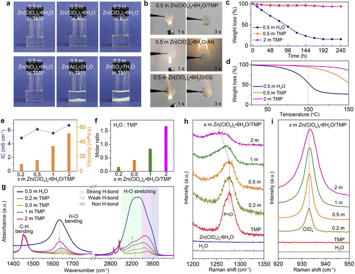
To screen hydrous organic electrolytes, we have selected four hydrated Zn-salts (Zn(ClO4)2·6H2O, Zn(NO3)2·6H2O, Zn(Ac)2·2H2O, and ZnSO4·7H2O) and five organic solvents (e.g., EG, AN, TMP, DMC, and DME) for comparison. Among them, TMP has been employed in Li/Na/K-based batteries as a fire-retardant co-solvent.10,44,45 As shown in Fig. 1a and S1 (ESI†), Zn(ClO4)2·6H2O can easily dissolve in all of the tested organic solvents to form transparent solutions. Ignition tests (Fig. 1b and S2, ESI†) demonstrate that the TMP-based electrolyte features non-flammable nature, whereas the other electrolytes based on AN, EG, DME, and DMC are highly flammable. Hydrated salts of Zn(Ac)2·2H2O and ZnSO4·7H2O are almost insoluble in TMP. Hydrated Zn(NO3)2·6H2O is soluble in TMP, but 0.5 m Zn(NO3)2·6H2O/TMP exhibits a weak Zn2+ plating/stripping process mainly due to its low ionic conductivity (1.26 mS cm−2, Fig. S3, ESI†). Thus, Zn(ClO4)2·6H2O in TMP solution has been chosen as the electrolyte for further evaluation.A batch of hydrous organic electrolytes were prepared by adding 0.2, 0.5, 1, and 2 mol kg−1 Zn(ClO4)2·6H2O in TMP, which are denoted as 0.2, 0.5, 1, and 2 m TMP, respectively. The Zn(ClO4)2·6H2O/TMP based electrolytes exhibit low volatility with 94% of the original weight after exposing to the atmosphere for 240 h, whereas the reference aqueous electrolyte (0.5 m Zn(ClO4)2·6H2O in H2O, denoted as 0.5 m H2O) quickly decreases to 31% after 120 h (Fig. 1c). The thermogravimetric analysis (TGA) curves in Fig. 1d reveal that TMP-based electrolytes exhibit negligible volatility up to 100 °C. In contrast, the 0.5 m H2O counterpart displays a faster weight loss of 45% on heating to 100 °C. The high thermal stability and non-flammability endow the TMP-based hydrous organic electrolyte with considerable safety.
Fig. 1e presents the ionic conductivity and viscosity of electrolytes with x m Zn(ClO4)2·6H2O in TMP. Increasing the Zn-salt concentration significantly increases the electrolyte viscosity from 15.2 mPa s (0.5 m) to 51.8 mPa s (2 m). A relatively high ionic conductivity of 6.13 mS cm−1 is observed in 0.5 m TMP (Fig. S4, ESI†), higher than those of reported organic Zn-based electrolytes. Moreover, 0.5 m TMP shows a higher Zn2+ transference number (0.49) than the aqueous counterpart (0.28) (Fig. S5, ESI†). In addition, the dilute hydrous electrolyte manifests enhanced hydrophilicity on Zn (Fig. S6, ESI†), which favors reducing the interfacial free energy on the Zn–electrolyte interface and homogenizing the Zn2+ deposition.26,28 The molar ratio of H2O to TMP gradually increases from 0.42 in 0.5 m TMP to 1.68 in 2 m TMP (Fig. 1f). The higher H2O content will contribute to a H2O-rich Zn2+-solvation shell, thus inevitably deteriorating the H2O-induced side reactions on Zn, as shown later.
FTIR and Raman spectra are recorded to probe the structural evolution of electrolytes as a function of the salt concentration. As shown in Fig. 1g, the broad O–H stretching vibration (2900–3700 cm−1) can be divided into three categories of H2O molecules with different H-bonding environments: bulk H2O with a strong H-bond (∼3200 cm−1), cluster H2O with a weak H-bond (∼3450 cm−1), and isolated H2O with a non-H-bond (∼3560 cm−1).27,46 The fitting results of different electrolytes are provided in Fig. S7 (ESI†). Increasing the Zn(ClO4)2·6H2O concentration leads to enhanced population of bulk and cluster H2O, suggesting the formation of a highly H-bonded water structure. Moreover, the H2O bending vibration exhibits a redshift from 0.2 to 2 m TMP, indicating the H-bond reformation between H2O molecules. The intensified strong H-bond environment of water will increase water activity and worsen water-induced interfacial side reactions.19,46 The signals located at 1400–1500 cm−1 and 2800–3000 cm−1 are attributed to C–H bending and stretching vibrations, respectively.32 From the Raman spectra, the P![[double bond, length as m-dash]](https://www.rsc.org/images/entities/char_e001.gif) O stretching vibration of TMP molecules experiences a blueshift from 0.2 to 0.5 m, signifying the strengthened Zn2+–TMP coordination (Fig. 1h).10,45 However, further increasing the concentration from 0.5 to 2 m renders a redshift of the P
O stretching vibration of TMP molecules experiences a blueshift from 0.2 to 0.5 m, signifying the strengthened Zn2+–TMP coordination (Fig. 1h).10,45 However, further increasing the concentration from 0.5 to 2 m renders a redshift of the P![[double bond, length as m-dash]](https://www.rsc.org/images/entities/char_e001.gif) O signal, demonstrating the replacement of TMP in the Zn2+-solvation sheath by H2O. In addition, the signal of the ClO4− anion30,32,47 intensifies along with a slight blueshift as the salt concentration increases, implying the presence of ClO4− in the Zn2+-solvation sheath (Fig. 1i).
O signal, demonstrating the replacement of TMP in the Zn2+-solvation sheath by H2O. In addition, the signal of the ClO4− anion30,32,47 intensifies along with a slight blueshift as the salt concentration increases, implying the presence of ClO4− in the Zn2+-solvation sheath (Fig. 1i).
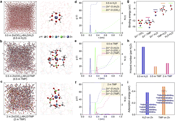
The effect of the Zn(ClO4)2·6H2O concentration on the electrolyte structure was further investigated by molecular dynamics (MD) simulations and density functional theory (DFT) calculations. Fig. 2a–c present the MD snapshots and typical Zn2+ solvation sheaths of 0.5 m H2O, 0.5 m TMP, and 2 m TMP, respectively. The compositions of these electrolytes for MD simulations are provided in Table S1 (ESI†). In 0.5 m TMP, the TMP solvent and ClO4− anion co-participate in the Zn2+ solvation sheath (Fig. 2b), which differs from that in 0.5 m H2O with a typical Zn[H2O]62+ structure (Fig. 2a). In the concentrated 2 m TMP, more H2O molecules insert into the Zn2+ solvation sheath to replace the solvating TMP (Fig. 2c), consistent with the aforementioned spectroscopic analyses. Radial distribution functions (RDFs) reflect the distributions of nearest-neighbor molecules, which further identify the structure evolution of electrolytes.27,30 The primary solvation shell of Zn2+ is around 0.4 nm in distance. In 0.5 m H2O, the average coordination numbers of Zn2+–H2O and Zn2+–ClO4− are 5.8 and 0.2, respectively (Fig. 2d). In TMP-based electrolytes, besides the Zn2+–H2O signal, two peaks involving Zn2+–O from Zn2+–ClO4− and Zn2+–TMP coordination appear at 0.33 and 0.36 nm, respectively (Fig. 2e). Accordingly, the primary Zn2+-solvation shell in 0.5 m TMP is occupied by 0.6H2O, 1.3 ClO4−, and 3.8 TMP on average, corresponding to Zn2+[H2O]0.6[ClO4−]1.3[TMP]3.8. In contrast, a H2O-rich Zn2+-solvation shell is detected in 2 m TMP electrolyte (i.e., Zn2+[H2O]2.5[ClO4−]2.3[TMP]1.4, Fig. 2f). Since the solvating-H2O exhibits a higher activity of reductive decomposition than the free H2O (Fig. S8, ESI†), the water-induced side reactions would inevitably occur in the concentrated hydrous organic electrolyte.
DFT calculations show that the binding energies between two ingredients follow the order of Zn2+–ClO4− < Zn2+–TMP < Zn2+–H2O (Fig. 2g). Considering the small size and high dielectric constant (ε = 78.5 for H2O vs. ε = 21.6 for TMP),45 H2O can favorably solvate with Zn2+ in the concentrated hydrous organic electrolyte. In addition, the binding energy of TMP–H2O is lower than that of H2O–H2O, implying feasible formation of a H-bond between TMP and H2O. According to MD simulations, the average H-bond number per H2O in 0.5 m H2O, 0.5 m TMP, and 2 m TMP is around 3.38, 0.95, and 1.35, respectively (Fig. 2h). The lower value of TMP electrolytes suggests a weakened water activity. Furthermore, the lower adsorption energy of TMP (−0.48 eV) than that of H2O (−0.38 eV) reveals that TMP preferentially absorbs on Zn, which favors constraining random Zn2+ deposition (Fig. 2i).
Zn surface/interface chemistry in different electrolytes
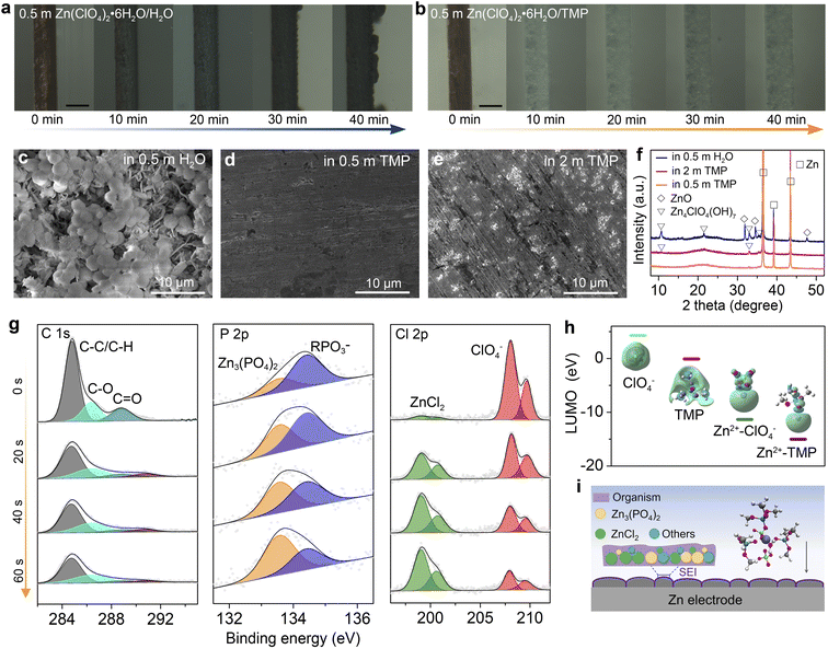
The Zn plating behavior in H2O and TMP-based electrolytes is probed in symmetric Zn//Cu cells using optical microscopy. In 0.5 m H2O, non-uniform Zn plating sites emerge after 20 min, and they gradually grow into dendritic Zn protrusions after 40 min at 10 mA cm−2 (Fig. 3a). In stark contrast, the 0.5 m TMP electrolyte enables a uniform and compact Zn plating (Fig. 3b). The chemical stability of Zn in electrolytes is compared by immersing Zn foil in H2O and TMP-based electrolytes (Fig. 3c–f and S9, ESI†). Massive flake-like and spherical by-products are observed on the Zn surface after soaking for 3 days in 0.5 m H2O (Fig. 3c). In addition, the XRD signals of ZnO and Zn4ClO4(OH)7 are detected on Zn after soaking in the aqueous electrolyte (Fig. 3f). By contrast, the Zn foil after soaking in 0.5 m TMP maintains a compact and smooth surface without any discernible by-product (Fig. 3d and f), identifying the effective suppression of water-induced side reactions on Zn by using the dilute hydrous TMP electrolyte. However, a small amount of Zn4ClO4(OH)7 with slight corrosion is observed after soaking Zn in the concentrated 2 m TMP (Fig. 3e and f). The by-product formation and Zn corrosion are mainly induced by the H2 evolution reaction (2H2O + 2e− → H2 + 2OH−; Zn → Zn2+ + 2e−), which increases the local pH near Zn and thus triggers the precipitation reaction of OH− with Zn2+, ClO4−, and H2O (e.g., Zn2+ + 2OH− → ZnO + H2O; 4Zn2+ + 7OH− + 4ClO4− → Zn4ClO4(OH)7).20,27,30 The different by-products in H2O-based and TMP-based electrolytes may be due to the difference in the Zn2+ solvation shell, where a ClO4−-rich Zn2+ solvation shell in 2 m TMP would favor forming the Zn4ClO4(OH)7 by-product.The surface and interphase chemistry on the cycled Zn electrode in 0.5 m TMP were analyzed using X-ray photoelectron spectroscopy (XPS) with Ar+ sputtering (Fig. 3g). The cycled Zn was harvested from a Zn//Zn cell after 10 cycles at 1 mA cm−2. On the top surface (before sputtering), there are strong C signals involving organic components (C–C/C–H and C–O) and organic RPO3− (R represents alkyl) species, which is ascribed to the incomplete reduction products of the organic TMP solvent.48,49 Moreover, the interphase contains the ClO4− component, which arises from the incomplete reduction of ClO4− or a trace salt residue on Zn. With the Ar+ sputtering, the signal of the organic species is apparently decreased, whereas inorganic components of Zn3(PO4)2 (134 eV)48,49 and ZnCl2 (200 eV)20 significantly intensify, confirming the decomposition of Zn2+–TMP and Zn2+–ClO4− complexes. After 60 s etching, the Zn3(PO4)2 content increases from 29.9% to 65.8%, and the ZnCl2 content increases from 4.5% to 49.7%, indicating the enrichment of inorganic species in the inner SEI layer. Zn3(PO4)2 and ZnCl2 have been identified as the primary rigid-frame materials in the SEI, wherein they can homogenize Zn2+ diffusion and suppress Zn corrosion.12,20,49 Note that ZnCl2 is almost insoluble in the 0.5 m TMP electrolyte (Fig. S10, ESI†).
DFT calculations further reveal that the lowest unoccupied molecular orbital (LUMO) energies of Zn2+–TMP and Zn2+–ClO4− coordinations are lower than those of free TMP and ClO4− (Fig. 3h), demonstrating the preferred electron reception of Zn2+–TMP and Zn2+–ClO4− from the anode. The electron feasibly transfers from the cation to the solvent/anion via the cation–solvent/anion unit, rendering the reductive decomposition of the solvent/anion and the presence of decomposed species in the SEI.27 Thus, the unique Zn2+ solvation sheath with the co-participation of TMP and ClO4− contributes to SEI formation on Zn. As illustrated in Fig. 3i, the in situ generated SEI, which is mainly composed of an organic-rich outer layer and a Zn3(PO4)2–ZnCl2 rich inner layer, can suppress the continuous parasitic reactions to stabilize the Zn electrode.
Electrochemical reversibility of Zn electrodes in different electrolytes
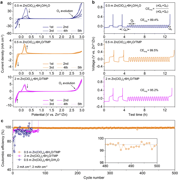
Fig. 4a compares the cyclic voltammograms (CVs) of Zn//Ti cells with different electrolytes from −0.3 to 3.0 V at 1 mV s−1. The redox couple located between −0.3 and 0.3 V is associated with the Zn2+ stripping/plating process. The 0.5 m H2O electrolyte exhibits a higher current response of Zn2+ stripping/plating because of high ionic conductivity but shows a rapid current decrease in the following cycles due to H2O-induced side reactions. Additionally, the severe O2 evolution appears at 2.5 V. In sharp contrast, the 0.5 m TMP electrolyte manifests a stable Zn2+ stripping/plating and achieves high anodic stability up to 3.0 V with negligible O2 evolution. In comparison, a slight decrease of current involving the Zn plating/stripping is observed in 2 m TMP after the first cycle, demonstrating reduced reversibility. An apparent O2 evolution is detected at 2.75 V, suggesting high H2O activity in the concentrated electrolyte.The coulombic efficiency (CE) of Zn2+ stripping/plating in different electrolytes was quantified using a ‘reservoir half-cell’ protocol.9 As shown in Fig. 4b, the Zn//Cu cells were first subjected to two cycles of charge/discharge at 1 mA cm−2 with an areal capacity of 1 mA h cm−2 and a cut-off voltage of 0.5 V to mitigate the substrate effects. Afterwards, 1 mA h cm−2 Zn (QP) was electro-plated on the Cu substrate as a Zn reservoir, which was then cycled at a fixed plating capacity of 0.2 mA h cm−2 (QC). After n cycles (e.g., 20), this cell was fully charged to 0.5 V to strip all removable Zn (QS). According to the equation shown in Fig. 4B, 0.5 m TMP enables a much higher average CE of 99.5% than 0.5 m H2O (89.4%), 1 m TMP (98.6%, Fig. S11, ESI†), and 2 m TMP (95.2%). Although 0.2 m TMP exhibits a respectable average CE of 99.4%, it shows a higher voltage polarization than that of 0.5 m TMP (Fig. S12, ESI†). Taking into consideration the comprehensive factors of ionic conductivity, viscosity, reversibility, the electrochemical window and cost, the dilute 0.5 m TMP is selected as the optimized electrolyte.
Besides, the dilute electrolyte can well support the stable cycling of the asymmetric Zn//Cu cell at 2 mA cm−2 with 2 mA h cm−2 (Fig. 4c and S13, ESI†). Impressively, the cell with 0.5 m TMP electrolyte shows a much higher initial CE of 95.9%, significantly outperforming those with 0.5 m H2O (80.2%) and 2 m TMP (83.6%). Additionally, the CE in 0.5 m TMP stabilizes at an average value of 99.5% over 500 cycles. In contrast, the cell using 0.5 m H2O displays unstable cycling with fluctuated CE values due to severe H2O-induced side reactions. The 2 m TMP moderately improves the reversibility but displays a short lifespan of 80 cycles with a lower CE below 97%. In comparison with reported Zn-based electrolytes (Table S2, ESI†), the as-designed 0.5 m TMP manifests superior performance in terms of initial and stable CEs.
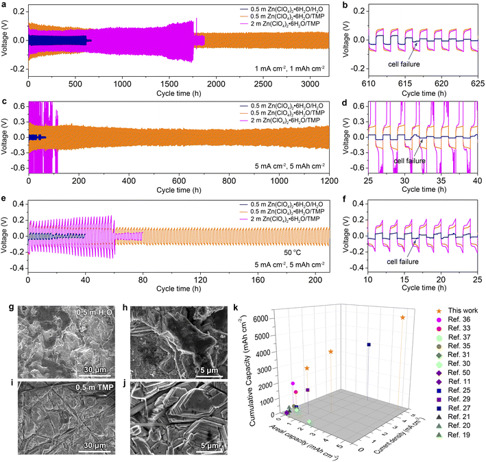
The electrochemical stability of Zn electrodes in different electrolytes was further evaluated using symmetric Zn//Zn cells. As shown in Fig. 5a and b, the cell in 0.5 m TMP can be stably cycled over 3200 h at a current density of 1 mA cm−2 and an areal capacity of 1 mA h cm−2. For comparison, the aqueous electrolyte gives rise to a short-circuit cell failure after 610 h, which is mainly caused by the dendrite growth and water-induced parasitic reactions on Zn. The concentrated 2 m TMP results in a shorter lifespan of 1750 h than that of the dilute one (Fig. S14, ESI†). Even at 5.0 mA h cm−2 and 5.0 mA cm−2, the cell with 0.5 m TMP manifests cycling stability over 1200 h with steady voltage curves (Fig. S15, ESI†) and significantly outperforms the 0.5 m H2O cell experiencing failure after only 30 h (Fig. 5c and d). At 5 mA cm−2, note that concentrated 2 m TMP incurs a large voltage polarization because of high electrolyte viscosity, while too diluted 0.2 m TMP cannot support stable cycling of Zn due to low conductivity (Fig. S16, ESI†). In addition, the Zn//Zn cell in 0.5 m TMP achieves a good rate performance even at a high current of 10 mA cm−2 (Fig. S17, ESI†). Furthermore, the formulated 0.5 m TMP endows the Zn//Zn cell with much improved high-temperature adaptability (50 °C) as compared to the counterparts 0.5 m H2O and 2 m TMP (Fig. 5e and f).
The cycled Zn electrodes were characterized by SEM and XRD to further assess the effect of dilute hydrous organic electrolyte on Zn stabilization. As shown in Fig. 5g and h, the Zn electrode dismantled from Zn//Zn cells after 100 cycles at 1 mA cm−2 in 0.5 m H2O presents a rough surface. In contrast, a compact and horizontal Zn surface is observed in 0.5 m TMP (Fig. 5i and j), while corrosion can be observed in 2 m TMP (Fig. S18, ESI†). Phase analysis further reveals indiscernible formation of a by-product in 0.5 m TMP but clear generation of ZnO in 0.5 m H2O and Zn4ClO4(OH)7 in 2 m TMP (Fig. S19, ESI†). Furthermore, the cycled Zn electrode in 0.5 m TMP exhibits a higher intensity ratio of Zn(002) to Zn(100) than that in the aqueous counterpart (6.28 vs. 4.93), contributing to the dendrite-free behavior in 0.5 m TMP. In addition, the formulated 0.5 m TMP in this study compares favorably with recently reported electrolytes for Zn-based battery chemistries such as concentrated hydrous organic electrolytes,36 anhydrous organic electrolytes,33,35,37 deep eutectic electrolytes,11,30,31,50 hybrid aqueous/organic electrolytes,25,27,29 and concentrated dual salt electrolytes19–21 (Fig. 5k). The dilute 0.5 m Zn(ClO4)2·6H2O/TMP electrolyte delivers an impressive cumulative capacity at a high rate (i.e., 6000 mA h cm−2 at 5 mA cm−2), standing out from the state-of-the-art Zn-based electrolytes.
Electrochemical performance of full Zn batteries
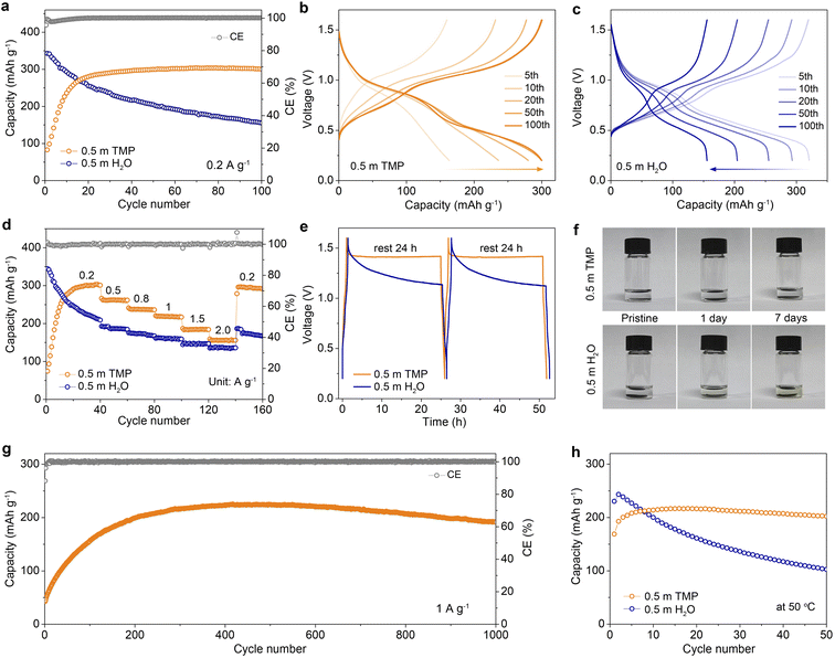
In addition to boosting Zn reversibility, the designed dilute hydrous organic electrolyte with low water activity can also improve the stability of vanadium oxide-based cathodes by suppressing the dissolution in aqueous media. Taking a conventional V-based cathode of Zn0.13V2O5·nH2O as an example (denoted as ZVO, Fig. S20, ESI†), we compare its cycling performances and voltage profiles in different electrolytes at 0.2 A g−1 (Fig. 6a–c). The Zn//0.5 m TMP//ZVO full cell exhibits an initial capacity increase, which is mainly ascribed to the activation process as confirmed by the decreased charge-transfer resistance during cycling (Fig. S21, ESI†). After 50 cycles, it achieves a stable capacity of 299.5 mA h g−1, indicating favorable compatibility between the 0.5 m TMP electrolyte and ZVO cathode. In contrast, the ZVO cathode in 0.5 m H2O experiences a rapid capacity decay during cycling and delivers a low capacity of 155.5 mA h g−1 with 45.3% capacity retention after 100 cycles (Fig. 6c). This poor cyclability can be attributed to the dissolution of vanadium from the cathode and the interfacial side reactions on Zn. In addition, the 0.5 m TMP electrolyte enables considerable rate stability with average reversible capacities of 262.4, 218.7, and 155.9 mA h g−1 at 0.5, 1, and 2 A g−1, respectively, exceeding those of the 0.5 m H2O counterpart (Fig. 6d and S22, ESI†). Remarkably, the average capacity in 0.5 m TMP can recover to 295.4 mA h g−1 (in the 150th cycle) as the current returns to 0.2 A g−1, again outperforming that in 0.5 m H2O.The advantage of the TMP-based electrolyte was also assessed by monitoring the open-circuit voltage evolution of a fully charged cell, which was subsequently discharged after 24 h of rest and tested by conducting the process twice (Fig. 6e). Considerable CE values of 98.1% and 99.1% are achieved in 0.5 m TMP for the first and second process, respectively, much higher than those in 0.5 m H2O (79.6% and 77.9%). Moreover, the cell using 0.5 m TMP exhibits a smaller voltage drop (∼0.18 V) after 24 h storage than that with 0.5 m H2O (∼0.47 V). To intuitively identify the dissolution of the active material in electrolytes, static soaking of ZVO cathodes was performed in different media (Fig. 6f). The 0.5 m TMP electrolyte remains colorless and transparent even after 7 days, whereas 0.5 m H2O turns light yellow after only 1 day. The significant suppression of ZVO dissolution contributes to the stable cycling of a full battery. In addition, the ZVO cathode with 0.5 m TMP achieves a reversible capacity of 223.9 mA h g−1 after 400 cycles and sustains a remarkable capacity retention of 82% with a nearly 100% CE after 1000 cycles at 1 A g−1 (Fig. 6g and S23, ESI†). Impressively, the 0.5 m TMP endows the cell with cycling stability at 0.5 A g−1 at a high operating temperature of 50 °C, in contrast to fast capacity decay in the aqueous cell (Fig. 6h and S24, ESI†). To further evaluate the potential for practical applications, we design the full battery coupling an ultrathin Zn anode (20 μm; 11.7 mA h cm−2) with a high mass loading VOH cathode (18.4 mg cm−2, Fig. S25, ESI†). This Zn//ZVO full battery manifests good cycling stability and delivers a reversible capacity of 5.22 mA h cm−2 (the 50th cycle), corresponding to a negative-to-positive capacity (N/P) ratio of 2.24.
Conclusions
In summary, we report a non-flammable, dilute, and hydrous organic electrolyte composed of hydrated Zn(ClO4)2·6H2O salt and fire-retardant TMP solvent for rechargeable Zn batteries. This electrolyte circumvents the issues of Zn electrodes such as H2 evolution, Zn corrosion, and dendrite formation in common aqueous electrolytes. The electrolyte structure, Zn interface chemistry, and Zn reversibility can be regulated by adjusting the Zn-salt concentration in TMP. The dilute 0.5 m TMP electrolyte is found to feature a H2O-poor Zn2+-solvation sheath and low water activity and exhibits a wider electrochemical window and a much higher Zn reversibility than the concentrated counterpart. Additionally, the unique Zn2+ solvation shell with the involvement of TMP and ClO4− not only enables a uniform Zn plating but also promotes the in situ formation of the Zn3(PO4)2–ZnCl2-rich interphase layer, contributing to a compact, dendrite-free, and corrosion-free Zn electrode. The formulated 0.5 m TMP allows a high Zn plating/stripping CE of 99.5% over 500 cycles in the Zn//Cu cell (2 mA h cm−2 at 2 mA cm−2) and sustains extended durability over 1200 h in the Zn//Zn cell (5 mA h cm−2 at 5 mA cm−2). Additionally, the 0.5 m TMP electrolyte suppresses the dissolution of the vanadium oxide cathode and enables a stable operation at high temperature (50 °C). This work broadens the horizon of dilute and non-flammable electrolytes to stabilize Zn electrodes and would guide the design of hydrous organic electrolytes for metallic batteries.Data availability
All experimental and computational data associated with this article have been included in the main text and ESI.†Author contributions
N. Z. and F. C. proposed the concept and supervised the work; G. M. and N. Z. carried out the experimental design, characterization and electrochemical measurement; L. M. performed the theoretical simulations; G. M. and W. Y. prepared the cathode materials; N. Z. and F. C. wrote and revised the paper.; W. Y., K. Q., M. L., and X. N. helped to discuss and analyze the data; all authors discussed and revised the manuscript.Conflicts of interest
There are no conflicts to declare.Acknowledgements
This work was supported by the National Natural Science Foundation of China (22075067 and 21925503), Natural Science Foundation of Hebei Province (B2020201001), Young Elite Scientists Sponsorship Program by CAST (2021QNRC001), the Haihe Laboratory of Sustainable Chemical Transformations (CYZC202110) and Research Innovation Team of College of Chemistry and Environmental Science of Hebei University (hxkytd2102).References
- S. Liu, R. Zhang, J. Mao, Y. Zhao, Q. Cai and Z. Guo, Sci. Adv., 2022, 8, eabn5097 CrossRef CAS PubMed.
- L. E. Blanc, D. Kundu and L. F. Nazar, Joule, 2020, 4, 771–799 CrossRef CAS.
- Z. Liu, Y. Huang, Y. Huang, Q. Yang, X. Li, Z. Huang and C. Zhi, Chem. Soc. Rev., 2020, 49, 180–232 RSC.
- P. Ruan, S. Liang, B. Lu, H. J. Fan and J. Zhou, Angew. Chem., Int. Ed., 2022, 61, e202200598 CrossRef CAS PubMed.
- N. Zhang, X. Chen, M. Yu, Z. Niu, F. Cheng and J. Chen, Chem. Soc. Rev., 2020, 49, 4203–4219 RSC.
- N. Dong, F. Zhang and H. Pan, Chem. Sci., 2022, 13, 8243–8252 RSC.
- D. Chao, W. Zhou, F. Xie, C. Ye, H. Li, M. Jaroniec and S.-Z. Qiao, Sci. Adv., 2020, 6, eaba4098 CrossRef CAS PubMed.
- J. Shin, J. Lee, Y. Park and J. W. Choi, Chem. Sci., 2020, 11, 2028–2044 RSC.
- L. Ma, M. A. Schroeder, O. Borodin, T. P. Pollard, M. S. Ding, C. Wang and K. Xu, Nat. Energy, 2020, 5, 743–749 CrossRef CAS.
- Z. Zeng, V. Murugesan, K. S. Han, X. Jiang, Y. Cao, L. Xiao, X. Ai, H. Yang, J.-G. Zhang, M. L. Sushko and J. Liu, Nat. Energy, 2018, 3, 674–681 CrossRef CAS.
- H. Qiu, X. Du, J. Zhao, Y. Wang, J. Ju, Z. Chen, Z. Hu, D. Yan, X. Zhou and G. Cui, Nat. Commun., 2019, 10, 5374 CrossRef PubMed.
- X. Zeng, J. Mao, J. Hao, J. Liu, S. Liu, Z. Wang, Y. Wang, S. Zhang, T. Zheng, J. Liu, P. Rao and Z. Guo, Adv. Mater., 2021, 33, 2007416 CrossRef CAS PubMed.
- Y. Chu, S. Zhang, S. Wu, Z. Hu, G. Cui and J. Luo, Energy Environ. Sci., 2021, 14, 3609–3620 RSC.
- Z. Cai, Y. Ou, B. Zhang, J. Wang, L. Fu, M. Wan, G. Li, W. Wang, L. Wang, J. Jiang, Z. W. Seh, E. Hu, X.-Q. Yang, Y. Cui and Y. Sun, J. Am. Chem. Soc., 2021, 143, 3143–3152 CrossRef CAS PubMed.
- H. Yang, Y. Qiao, Z. Chang, H. Deng, X. Zhu, R. Zhu, Z. Xiong, P. He and H. Zhou, Adv. Mater., 2021, 33, 2102415 CrossRef CAS PubMed.
- G. Liang, J. Zhu, B. Yan, Q. Li, A. Chen, Z. Chen, X. Wang, B. Xiong, J. Fan, J. Xu and C. Zhi, Energy Environ. Sci., 2022, 15, 1086–1096 RSC.
- H. Liu, J.-G. Wang, W. Hua, L. Ren, H. Sun, Z. Hou, Y. Huyan, Y. Cao, C. Wei and F. Kang, Energy Environ. Sci., 2022, 15, 1872–1881 RSC.
- X. Nie, L. Miao, W. Yuan, G. Ma, S. Di, Y. Wang, S. Shen and N. Zhang, Adv. Funct. Mater., 2022, 32, 2203905 CrossRef CAS.
- F. Wang, O. Borodin, T. Gao, X. Fan, W. Sun, F. Han, A. Faraone, J. A. Dura, K. Xu and C. Wang, Nat. Mater., 2018, 17, 543–549 CrossRef CAS PubMed.
- Y.-P. Zhu, J. Yin, X. Zheng, A.-H. Emwas, Y. Lei, O. F. Mohammed, Y. Cui and H. N. Alshareef, Energy Environ. Sci., 2021, 14, 4463–4473 RSC.
- M. Yang, J. Zhu, S. Bi, R. Wang and Z. Niu, Adv. Mater., 2022, 34, 2201744 CrossRef CAS PubMed.
- X. Ji, eScience, 2021, 1, 99–107 CrossRef.
- C. Li, W. Yuan, C. Li, H. Wang, L. Wang, Y. Liu and N. Zhang, Chem. Commun., 2021, 57, 4319–4322 RSC.
- R. Qin, Y. Wang, M. Zhang, Y. Wang, S. Ding, A. Song, H. Yi, L. Yang, Y. Song, Y. Cui, J. Liu, Z. Wang, S. Li, Q. Zhao and F. Pan, Nano Energy, 2021, 80, 105478 CrossRef CAS.
- L. Cao, D. Li, E. Hu, J. Xu, T. Deng, L. Ma, Y. Wang, X.-Q. Yang and C. Wang, J. Am. Chem. Soc., 2020, 142, 21404–21409 CrossRef CAS PubMed.
- J. Hao, L. Yuan, C. Ye, D. Chao, K. Davey, Z. Guo and S.-Z. Qiao, Angew. Chem., Int. Ed., 2021, 60, 7366–7375 CrossRef CAS PubMed.
- Y. Dong, L. Miao, G. Ma, S. Di, Y. Wang, L. Wang, J. Xu and N. Zhang, Chem. Sci., 2021, 12, 5843–5852 RSC.
- G. Ma, L. Miao, Y. Dong, W. Yuan, X. Nie, S. Di, Y. Wang, L. Wang and N. Zhang, Energy Storage Mater., 2022, 47, 203–210 CrossRef.
- F. Ming, Y. Zhu, G. Huang, A.-H. Emwas, H. Liang, Y. Cui and H. N. Alshareef, J. Am. Chem. Soc., 2022, 144, 7160–7170 CrossRef CAS PubMed.
- W. Yang, X. Du, J. Zhao, Z. Chen, J. Li, J. Xie, Y. Zhang, Z. Cui, Q. Kong, Z. Zhao, C. Wang, Q. Zhang and G. Cui, Joule, 2020, 4, 1557–1574 CrossRef CAS.
- X. Lin, G. Zhou, M. J. Robson, J. Yu, S. C. T. Kwok and F. Ciucci, Adv. Funct. Mater., 2022, 32, 2109322 CrossRef CAS.
- Y. Dong, S. Di, F. Zhang, X. Bian, Y. Wang, J. Xu, L. Wang, F. Cheng and N. Zhang, J. Mater. Chem. A, 2020, 8, 3252–3261 RSC.
- A. Naveed, H. Yang, J. Yang, Y. Nuli and J. Wang, Angew. Chem., Int. Ed., 2019, 58, 2760–2764 CrossRef CAS PubMed.
- C. Pan, R. Zhang, R. G. Nuzzo and A. A. Gewirth, Adv. Energy Mater., 2018, 8, 1800589 CrossRef.
- N. Zhang, Y. Dong, Y. Wang, Y. Wang, J. Li, J. Xu, Y. Liu, L. Jiao and F. Cheng, ACS Appl. Mater. Interfaces, 2019, 11, 32978–32986 CrossRef CAS PubMed.
- D. Han, C. Cui, K. Zhang, Z. Wang, J. Gao, Y. Guo, Z. Zhang, S. Wu, L. Yin, Z. Weng, F. Kang and Q.-H. Yang, Nat. Sustain., 2022, 5, 205–213 CrossRef.
- V. Verma, R. M. Chan, L. Jia Yang, S. Kumar, S. Sattayaporn, R. Chua, Y. Cai, P. Kidkhunthod, W. Manalastas and M. Srinivasan, Chem. Mater., 2021, 33, 1330–1340 CrossRef CAS.
- S.-D. Han, N. N. Rajput, X. Qu, B. Pan, M. He, M. S. Ferrandon, C. Liao, K. A. Persson and A. K. Burrell, ACS Appl. Mater. Interfaces, 2016, 8, 3021–3031 CrossRef CAS PubMed.
- X. Qiu, N. Wang, X. Dong, J. Xu, K. Zhou, W. Li and Y. Wang, Angew. Chem., Int. Ed., 2021, 60, 21025–21032 CrossRef CAS PubMed.
- L. Ma, J. Vatamanu, N. T. Hahn, T. P. Pollard, O. Borodin, V. Petkov, M. A. Schroeder, Y. Ren, M. S. Ding, C. Luo, J. L. Allen, C. Wang and K. Xu, Proc. Natl. Acad. Sci. U.S.A., 2022, 119, e2121138119 CrossRef CAS PubMed.
- X. Liu, H. Zhang, D. Geiger, J. Han, A. Varzi, U. Kaiser, A. Moretti and S. Passerini, Chem. Commun., 2019, 55, 2265–2268 RSC.
- Z. Wang, M. Zhou, L. Qin, M. Chen, Z. Chen, S. Guo, L. Wang, G. Fang and S. Liang, eScience, 2022, 2, 209–218 CrossRef.
- N. Zhang, Y. Dong, M. Jia, X. Bian, Y. Wang, M. Qiu, J. Xu, Y. Liu, L. Jiao and F. Cheng, ACS Energy Lett., 2018, 3, 1366–1372 CrossRef CAS.
- J. Wang, Y. Yamada, K. Sodeyama, E. Watanabe, K. Takada, Y. Tateyama and A. Yamada, Nat. Energy, 2018, 3, 22–29 CrossRef CAS.
- S. Liu, J. Mao, L. Zhang, W. K. Pang, A. Du and Z. Guo, Adv. Mater., 2021, 33, 2006313 CrossRef CAS PubMed.
- Y. Wang, T. Wang, D. Dong, J. Xie, Y. Guan, Y. Huang, J. Fan and Y.-C. Lu, Matter, 2022, 5, 162–179 CrossRef CAS.
- M. G. Giorgini, K. Futamatagawa, H. Torii, M. Musso and S. Cerini, J. Phys. Chem. Lett., 2015, 6, 3296–3302 CrossRef CAS.
- S. Di, X. Nie, G. Ma, W. Yuan, Y. Wang, Y. Liu, S. Shen and N. Zhang, Energy Storage Mater., 2021, 43, 375–382 CrossRef.
- L. Cao, D. Li, T. Deng, Q. Li and C. Wang, Angew. Chem., Int. Ed., 2020, 59, 19292–19296 CrossRef CAS PubMed.
- J. Shi, T. Sun, J. Bao, S. Zheng, H. Du, L. Li, X. Yuan, T. Ma and Z. Tao, Adv. Funct. Mater., 2021, 31, 2102035 CrossRef CAS.
Footnotes |
| † Electronic supplementary information (ESI) available. See https://doi.org/10.1039/d2sc04143j |
| ‡ These authors contributed equally to this work. |
| This journal is © The Royal Society of Chemistry 2022 |

