Self-supported metal–organic framework-based nanostructures as binder-free electrodes for supercapacitors
Xueyan
Zhao
,
Kai
Tao
 * and
Lei
Han
 *
*
School of Materials Science & Chemical Engineering, Ningbo University, Ningbo, Zhejiang 315211, China. E-mail: taokai@nbu.edu.cn; hanlei@nbu.edu.cn
First published on 14th January 2022
Abstract
Metal–organic frameworks (MOFs), an interesting class of functional inorganic materials, have recently emerged as suitable electrode materials or templates/precursors of electrode materials for supercapacitors (SCs). The key in utilizing MOF-based electrode materials is to address the low electronic conductivity and poor stability issues. Therefore, the rational design and fabrication of self-supported binder-free electrodes is considered the most promising strategy to address these challenges. In this review, we summarize the recent advances in the design and manufacture of self-supported MOF-based nanostructures and their use as binderless electrodes for SCs, especially over the last five years. The synthesis strategies for constructing pristine MOFs, MOF composites and MOF derivative arrays are overviewed. By highlighting the advantages and challenges of each class of electrode materials, we hope that this review will provide some insights into the rational design of MOF-based electrode materials to promote the future development of this highly exciting field.
1 Introduction
Global demands for the transmission and storage of renewable energy sources such as solar and wind energy have pushed the development of efficient electrochemical energy conversion and storage technologies including rechargeable batteries, fuel cells and supercapacitors (SCs).1–9 SCs are promising candidates due to their high power density, rapid charge storage capability, and impressive cycling stability.10,11 Electrode materials with high capacitance, good rate capability and decent durability are essential for robust and efficient energy storage devices.12 Rational optimization of nanostructured electrode materials is a promising strategy to maximize the efficiency of SCs.13–15 Recently, many novel materials have been explored as electrode materials for SCs, and metal–organic frameworks (MOFs) stand out from the rest due to their high specific surface area and potential pseudocapacitance sites.16–18MOFs are a kind of porous crystalline material formed by the self-assembly of metal ions/clusters and organic ligands under certain conditions.19,20 The structure of MOFs can be manipulated by changing the valence states of metal ions and the types of organic ligands. The good crystallinity, large surface area and excellent structural tunability make MOFs the best candidates for high-performance electrode materials.21 However, the straightforward application of pristine MOFs is impeded by the relatively low electronic conductivity and poor stability during the electrochemical process. Alternatively, MOFs can be transformed into porous carbon, metal oxides/hydroxides, metal sulfides, etc., wherein MOFs are utilized as templates/precursors. MOF derivatives can largely inherit the morphology and high porosity of MOF templates. Therefore, MOFs and MOF-derived electrode materials have attracted increasing attention for application in SCs. Nevertheless, powdery MOF-based electrode materials need to be blended with an insulating polymer binder to form a paste and loaded on a current collector.22,23 This electrode preparation method suffers from problems such as significant interfacial resistance between the active material and the conductive substrate, forming a “dead volume” and stripping of the active materials, which degrades the advantages of MOF-based electrode materials.24,25 To overcome these problems, fabricating self-supported MOF-based nanostructures on conductive substrates (nickel foam, carbon cloth, copper foam, etc.) without adding binders and conductive additives is a good choice.26–28 Compared with powdery electrode materials, self-supported binder-free electrodes have the following advantages: (1) direct growth of electroactive materials on conductive substrates simplifies the electrode preparation process. (2) The binder-free electrode ensures rapid electron transfer and good interface contact between the active materials and the substrate. (3) The aligned nanostructures effectively prevent the collapse of electrode materials and expose more electroactive sites.29–34 In this regard, many MOF-based electrode materials have been directly fabricated on conductive substrates in the forms of self-supported one-dimensional (1D), two-dimensional (2D) and three-dimensional (3D) nanostrucutures in recent years (Scheme 1).35–38
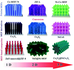 | ||
| Scheme 1 Schematic illustration of the typical geometry of self-supported MOF-based electrodes for SCs. | ||
A large number of excellent reviews have been published in recent years focusing on MOF-based materials and their applications in energy-related fields.37 For example, in 2015, Zou and Xu et al.39 gave a critical review on the design principles and strategies for MOFs and MOF-derived nanostructures, and their applications in electrochemical energy storage and conversion. However, powdery MOF-based electrode materials almost dominated the SC applications in these reviews. Given that the integrated electrodes have great promise in SCs, and a growing number of self-supported MOF-based nanostructures have been utilized as binder-free electrodes during the last few years, it is time to give an overview on this topic.
This review will summarize the recent advances in the synthetic strategies of self-supported MOF-based nanostructures, and their utilization as binder-free electrodes for SCs. The challenges faced in this field and the possible solutions to overcome these challenges in order to advance future developments are discussed. Representative works on self-supported MOF-based nanostructures as binder-free electrodes for SCs are listed in Table 1.
| MOF | Electrode | Electrolyte | Capacitance | Capacitance retention | Ref. |
|---|---|---|---|---|---|
| Pristine MOF arrays | |||||
| Cu–CAT | Cu–CAT NWAs | 3 M KCl | 202 F g−1 at 0.5 A g−1 | 80% 5000 cycles | 40 |
| ZIF-67 | TC-ZIF-67 | 2 M KOH | 1.756 F cm−2 at 2 mA cm−2 | 103% 15![[thin space (1/6-em)]](https://www.rsc.org/images/entities/char_2009.gif) 000 cycles 000 cycles |
44 |
| Co-MOF | Co-MOF nanoplate arrays | 2 M KOH | 8.56 C cm−2 at 5 mA cm−2 | 84% 5000 cycles | 45 |
| Ni/Co-MOF | Ni/Co-MOF@CC | 2 M KOH | 1180.5 mC cm−2 at 3 mA cm−2 | 97.6% 5000 cycles | 50 |
| MOF composite arrays | |||||
| Ni-MOF | Co3O4@Ni-MOF/NF | 1 M KOH | 1980.7 F g−1 at 1 A g−1 | 82.2% 2000 cycles | 57 |
| Ni-MOF | NiCo2O4@Ni-MOF/NF | 2 M KOH | 208.8 mA h g−1 at 2 mA cm−2 | — | 58 |
| ZIF-8 | ZnO@ZIF-8/CF | 1 M H2SO4 | 390 F g−1 at 2 mV s−1 | 88% 10![[thin space (1/6-em)]](https://www.rsc.org/images/entities/char_2009.gif) 000 cycles 000 cycles |
64 |
| MOF derivative arrays | |||||
| Carbons | |||||
| ZIF-67 | RPCF/CC | 1 M Na2SO4 | 1049 mF cm−2 at 12 mA cm−2 | 98.4% 6000 cycles | 70 |
| Co-ZIF | Co–ZIF-450/CC | 2 M KOH | 1177 mF cm−2 at 1 mA cm−2 | 94% 10![[thin space (1/6-em)]](https://www.rsc.org/images/entities/char_2009.gif) 000 cycles 000 cycles |
71 |
| Metal oxides | |||||
| Co-MOF | Co3O4/C NAs/NF | 3 M KOH | 1.32 F cm−2 at 1 mA cm−2 | 96% 2000 cycles | 72 |
| Co–Ni-MOF | 2D-CMO/NF | 4 M KOH | 2098 mF cm−2 at 1 mA cm−2 | 92% 4200 cycles | 79 |
| Co-MOF | ZnCo2O4@NC/CTs | 1 M KOH | 278.3 mA h g−1 at 2 mA cm−2 | 99.4% 10![[thin space (1/6-em)]](https://www.rsc.org/images/entities/char_2009.gif) 000 cycles 000 cycles |
80 |
| CoNiMn-MOF | Co3O4/NiO/Mn2O3/NF | 6 M KOH | 3652 mF cm−2 at 1 mA cm−2 | 87.6% 10![[thin space (1/6-em)]](https://www.rsc.org/images/entities/char_2009.gif) 000 cycles 000 cycles |
81 |
| Zn–Co-MOF | ZNCO/rGO/NF | 2 M KOH | 267 mA h g−1 at 1 A g−1 | 90.2% 6000 cycles | 82 |
| Metal sulfides | |||||
| Co-ZIF-L | Co9S8–NSA/NF | 1 M KOH | 1098.8 F g−1 at 0.5 A g−1 | 87.4% 1000 cycles | 24 |
| Zn/Co-MOF | Zn–Co–S/NF | 1 M KOH | 2354.3 F g−1 at 0.5 A g−1 | 88.6% 1000 cycles | 87 |
| Co-MOF | Fe–Co–S/NF | 1 M KOH | 2695 F g−1 at 1 A g−1 | 84% 1000 cycles | 73 |
| NiCo-MOF | NiCo–S/NF | 3 M KOH | 3724 F g−1 at 1 A g−1 | — | 88 |
| Zn–Co-ZIF | Ni–Zn–Co–S NSAs/NF | 3 M KOH | 1.11 mA h cm−2 at 10 mA cm−2 | 85% 1000 cycles | 89 |
| Composite arrays derived from MOFs | |||||
| Co-MOF | Co3O4@CoNi2S4/CC | 2 M KOH | 244.4 mA h g−1 at 1 A g−1 | — | 94 |
| Co-MOF-L | Co3O4@NiCo2O4/NF | 1 M KOH | 544.2 C g−1 at 1 A g−1 | 93% 5000 cycles | 95 |
| ZIF-67 | LDH@CoS/NF | 6 M NaOH | 1205 F g−1 at 1 A g−1 | 88.5% 2000 cycles | 97 |
| MMO@Co3O4/NF | 6 M NaOH | 781 F g−1 at 1 A g−1 | 53.7% 2000 cycles | ||
| Spinelle@C/NF | 6 M NaOH | 692 F g−1 at 1 A g−1 | 81.9% 2000 cycles | ||
| ZIF-67 | Ni–Mo–Co–S NCAs/NF | 3 M KOH | 1.96 mA h cm−2 at 5 mA cm−2 | 91% 5000 cycles | 98 |
| ZIF-67 | CC@CoO@S–Co3O4 | 2 M KOH | 1013 mF cm−2 at 1 mA cm−2 | 67.7% 5000 cycles | 99 |
| ZIF-67 | Zn0.76Co0.24S CSNSAs | 3 M KOH | 1202 C g−1 at 1 A g−1 | 92% 5000 cycles | 100 |
2 Self-supported MOF nano-structures
The large specific surface area and inherent redox characteristics make MOFs ideal electrode materials. The bottleneck for the direct use of pristine MOFs in SCs is their low electronic conductivity and poor stability. The electrochemical properties of MOFs can be optimized by preparing self-supported electrodes through the design of multiple morphologies. Besides, coupling with other electrode materials is also an effective strategy to boost the electrochemical performance of MOFs.2.1 Synthesis of pristine MOF arrays
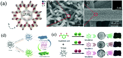 | ||
| Fig. 1 (a) Crystal structure of Cu–CAT viewed along the c-axis and (b and c) SEM images of Cu–CAT NWAs growing on carbon fiber paper. Reprinted with permission from ref. 40, Copyright 2017, Wiley-VCH. (d) Schematic illustration of the synthesis of faveolate Co-MOF nanosheets and Co-MOF nanoplate arrays. Reprinted with permission from ref. 45, Copyright 2021, Elsevier. (e) Schematic diagram of the synthesis process of Ni/Co-MOF with different molar ratios of Co/Ni. Reprinted with permission from ref. 49, Copyright 2021, Royal Society of Chemistry. | ||
Recently, 2D materials have emerged as ideal electrode materials for SCs. The atomic thicknesses with short paths and large lateral dimensions of 2D materials allow fast mass transport and superior electron transfer.12,41–43 Due to the synergistic advantages of 2D nanostructures, MOFs and self-supported configurations, 2D MOF nanoarrays, including nanosheets and nanowalls, have attracted extensive attention. Cobalt-based MOFs represent important MOF materials that have shown promising applications in electrochemical energy storage. In this context, Ma et al. reported the in situ growth of cobalt-based zeolitic imidazolate framework-67 (Co-ZIF-67) flakes on textile carbon cloth (TC) by a simple immersing method.44 TC was composed of helical carbon fibers with many wrinkles. These wrinkles increased the adsorption of Co ions on TC, thus facilitating the nucleation and growth of ZIF-67 nanocystals on the TC substrate. TC-ZIF-67 showed extremely improved conductivity compared with ZIF-67. As a free-standing electrode for SCs, TC-ZIF-67 displayed an areal capacitance of 1.756 F cm−2. More importantly, the electrode exhibited outstanding cycling stability. About 103% of the initial capacitance was retained even after 15![[thin space (1/6-em)]](https://www.rsc.org/images/entities/char_2009.gif) 000 cycles at a current density of 40 mA cm−2. Similarly, Zhang and co-workers used polyvinylpyrrolidone (PVP) as a regulator to prepare vertical Co-MOF nanoplate arrays on NF, while faveolate nanosheets were obtained without adding PVP (Fig. 1d).45 When utilized as binder-free electrodes for SCs, both electrodes with different morphologies showed excellent electrochemical performance. Particularly, the vertical Co-MOF nanoplate arrays delivered a much higher areal capacity (8.56 C cm−2) at a current density of 5 mA cm−2 compared with faveolate Co-MOF nanosheets (2.4 C cm−2). This was explained by the fact that the vertical nanoplate array structure was much more beneficial for the ion transport and infiltration of electrolytes. Nickel-based MOFs are also widely explored as electrode materials for SCs due to their high electrochemical activity. For example, Yang et al. reported a layered 2D Ni-MOF grown directly on NF, which exhibited a high specific capacitance due to the layered structure and favourable exposed facets.46 Bimetallic MOFs with multiple valence states and improved electronic conductivity were more appealing as electrode materials for SCs than single-metal MOFs.47 Wang et al. fabricated a triangular array of bimetallic Ni–Co MOF nanosheets on NF by one-step hydrothermal synthesis.48 The tight connection between the aligned MOF arrays and NF ensured a fast charge transfer. Interestingly, by adjusting the molar ratio of Ni to Co, NiCo-MOF/NF with a Ni/Co ratio of 3
000 cycles at a current density of 40 mA cm−2. Similarly, Zhang and co-workers used polyvinylpyrrolidone (PVP) as a regulator to prepare vertical Co-MOF nanoplate arrays on NF, while faveolate nanosheets were obtained without adding PVP (Fig. 1d).45 When utilized as binder-free electrodes for SCs, both electrodes with different morphologies showed excellent electrochemical performance. Particularly, the vertical Co-MOF nanoplate arrays delivered a much higher areal capacity (8.56 C cm−2) at a current density of 5 mA cm−2 compared with faveolate Co-MOF nanosheets (2.4 C cm−2). This was explained by the fact that the vertical nanoplate array structure was much more beneficial for the ion transport and infiltration of electrolytes. Nickel-based MOFs are also widely explored as electrode materials for SCs due to their high electrochemical activity. For example, Yang et al. reported a layered 2D Ni-MOF grown directly on NF, which exhibited a high specific capacitance due to the layered structure and favourable exposed facets.46 Bimetallic MOFs with multiple valence states and improved electronic conductivity were more appealing as electrode materials for SCs than single-metal MOFs.47 Wang et al. fabricated a triangular array of bimetallic Ni–Co MOF nanosheets on NF by one-step hydrothermal synthesis.48 The tight connection between the aligned MOF arrays and NF ensured a fast charge transfer. Interestingly, by adjusting the molar ratio of Ni to Co, NiCo-MOF/NF with a Ni/Co ratio of 3![[thin space (1/6-em)]](https://www.rsc.org/images/entities/char_2009.gif) :
:![[thin space (1/6-em)]](https://www.rsc.org/images/entities/char_2009.gif) 2 showed the best electrochemical performance. The optimal NiCo-MOF/NF could provide a high specific capacitance of 2230 F g−1 at 1 A g−1, and a hybrid SC made with NiCo-MOF/NF and activated carbon (AC) could provide excellent energy density (34.3 W h kg−1) at a power density of 375 W kg−1. The construction of bimetallic MOF nanoarrays on conductive substrates could significantly improve the electrochemical performance of MOF electrode materials in SCs.
2 showed the best electrochemical performance. The optimal NiCo-MOF/NF could provide a high specific capacitance of 2230 F g−1 at 1 A g−1, and a hybrid SC made with NiCo-MOF/NF and activated carbon (AC) could provide excellent energy density (34.3 W h kg−1) at a power density of 375 W kg−1. The construction of bimetallic MOF nanoarrays on conductive substrates could significantly improve the electrochemical performance of MOF electrode materials in SCs.
Compared with low-dimensional nanostructures, 3D nanostructures have larger accessible surface areas and interconnected networks, which are conducive to redox reactions. Therefore, various 3D MOF nanostructures, such as flowers and honeycombs, have been integrated with conductive substrates. As a typical example of self-supported 3D MOF electrodes, Chen et al.50 fabricated a porous Ni/Co based MOF with a honeycomb structure directly on carbon cloth (Ni/Co-MOF@CC) though a hydrothermal method using H32Mo7N6O28 as a catalyst. The good electrical conductivity and the porous wasp-like structure endowed the Ni/Co-MOF@CC electrode with good electrochemical properties. The prepared Ni/Co-MOF@CC electrode exhibited a high specific capacitance of 1180.5 mC cm−2 at 3 mA cm−2 and good rate performance (624.1 mC cm−2 at 60 mA cm−2). In addition to designing MOFs into a honeycomb structure, Ren and co-workers prepared a series of flower-like bimetallic Ni/Co-MOFs on NF using a simple solvothermal synthesis method (Fig. 1e).49 The composition and morphology of the flower-like bimetallic Ni/Co-MOFs can be adjusted by changing the Ni/Co ratio (molar) of the synthesis solution. As a binder-free SC electrode, the optimal sample displayed an excellent specific capacitance of 1230.3 F g−1 at a current density of 1 A g−1. The assembled solid-state asymmetric supercapacitor (ASC) using the optimal sample as the positive electrode and AC as the negative electrode exhibited an ultra-high energy density of 116 W h kg−1 at a power density of 0.79 kW kg−1 and a superior stability with 92.1% initial capacitance retention even after 6000 cycles at 10 A g−1.
The above results indicate that the drawbacks (i.e. poor electrical conductivity and structural instability) of pristine MOFs can partially be overcome by designing them into on self-supported 1D, 2D and 3D nanostructures on conductive substrates, and the in situ growth method provides a straightforward strategy to fabricate such nanostructures. It should be noted that careful control of the synthesis parameter is needed to obtain the desirable morphology and compositions.
![[thin space (1/6-em)]](https://www.rsc.org/images/entities/char_2009.gif) 200 W kg−1. Xu et al. prepared a layered-structure CoNi-MOF with ultrathin nanosheets and nanotube arrays directly on CC using Co(OH)2 as the template and Co source (Fig. 2d).53 The synthesized CC/CoNi-MOF showed a high areal capacity (1.0 C cm−2) at 2 mA cm−2 and good rate capability (61.4% retention at 15 mA cm−2). A hybrid SC was successfully fabricated with CC/CoNi-MOF as a positive electrode and reduced graphene oxide–carbon nanotubes as a negative electrode, and it delivered a maximum areal capacitance of 846 mF cm−2 at 1 m A cm−2 corresponding to a high energy density of 55.5 W h kg−1 at 175.5 W kg−1, and excellent cycling stability (96.5% after 10
200 W kg−1. Xu et al. prepared a layered-structure CoNi-MOF with ultrathin nanosheets and nanotube arrays directly on CC using Co(OH)2 as the template and Co source (Fig. 2d).53 The synthesized CC/CoNi-MOF showed a high areal capacity (1.0 C cm−2) at 2 mA cm−2 and good rate capability (61.4% retention at 15 mA cm−2). A hybrid SC was successfully fabricated with CC/CoNi-MOF as a positive electrode and reduced graphene oxide–carbon nanotubes as a negative electrode, and it delivered a maximum areal capacitance of 846 mF cm−2 at 1 m A cm−2 corresponding to a high energy density of 55.5 W h kg−1 at 175.5 W kg−1, and excellent cycling stability (96.5% after 10![[thin space (1/6-em)]](https://www.rsc.org/images/entities/char_2009.gif) 000 cycles).
000 cycles).
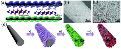 | ||
| Fig. 2 (a) The schematic illustration of the synthesis of CoNi-MOF, and the SEM images of (b) the Co(OH)2 precursor and (c) CoNi-MOF. Reprinted with permission from ref. 51, Copyright 2017, Wiley-VCH. (d) Schematic illustration of the preparation of CC/CoNi-MOF. (i) Formation of ZnO nanoarrays, (ii) deposition of Co(OH)2 nanosheets and (iii) transformation of Co(OH)2 to CoNi-MOF. Reprinted with permission from ref. 53, Copyright 2020, Elsevier. | ||
The above results show that the template strategy is an effective way to construct MOF arrays on conductive substrates. The metal oxide/hydroxide template guides the oriented growth of MOF crystals and is also acted as a metal ion source for MOF growth.54 This greatly optimizes the connection of the active materials to the substrate, giving rise to improved mechanic stability and electronic conductivity. This strategy provides a universal protocol for designing self-supported MOF nanostructures by choosing proper templates and organic linkers. However, the crystal size and shape of the MOF structures depend strongly on the physicochemical properties of the template and the synthesis parameters. Therefore, precise control of the synthesis parameters is required.
As electrodes, MOF arrays are advantageous to MOF powders since non-conductive binders and conductive additives are avoided. Besides, the orientated nanocystals are beneficial for the electrode kinetics. However, the electrochemical performance of single MOFs is still limited.
2.2 Synthesis of MOF composite arrays
To overcome the intrinsic low electronic conductivity and instability of pristine MOFs, it is commonly combined with conductive materials (e.g., carbon nanotubes, graphene, and conductive polymers) to form a MOF composite, which exhibits improved electrochemical properties. However, the aggregation of MOF particles is unavoidable, and the porous structure of the MOF is blocked to some extent. Besides, the powdery MOF composite is needed to be mixed with conductive additives and polymer binders to prepare the electrode, resulting in a low utilization of active sites and a large electrical resistance, which deteriorates the electrochemical performance of the MOF composite. Thus, it is desirable to integrate MOFs with an array of secondary electrode materials to form MOF composite arrays as binder-free electrodes for SCs. In this circumstance, transition metal oxides (TMOs) are ideal scaffolds for anchoring MOFs since they can be designed into various nanoarrays through a simple hydrothermal synthesis or electrodeposition. Therefore, this section will focus on the hybridization of TMOs with MOFs on conductive substrates to form free-standing electrodes for SCs.10,55,56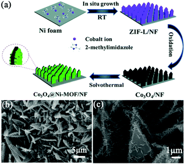 | ||
| Fig. 3 (a) Schematic illustration of the preparation of Co3O4@Ni-MOF/NF. (b and c) SEM images of the as-prepared Co3O4@Ni-MOF/NF. Reprinted with permission from ref. 57, Copyright 2021, Royal Society of Chemistry. | ||
Compared with monometallic oxides, mixed-metal TMOs possess higher conductivity and undergo richer redox reactions. As a result, spinel MCo2O4 (M = Zn and Ni) is more appealing as electrode material. Li et al. prepared a NiCo2O4 nanowire array on carbon fiber (CF) by a simple two-step method, which was utilized as a scaffold for anchoring MOF crystals (Fig. 4a).58 The growth of Ni-MOF nanosheets on the surface of NiCo2O4 nanowires was modulated by the reaction time and the concentration of the synthesis solution. The quantity of Ni-MOF shells was progressively increased with the increase of reaction time from 3 to 24 h (Fig. 4b–e) and the concentration of the synthesis solution. The optimized NiCo2O4@Ni-MOF composite array electrode showed excellent specific capacity (208.8 mA h g−1 at 2 mA cm−2). Furthermore, the assembled NiCo2O4@Ni-MOF//AC ASC device exhibited a maximum energy density of 32.6 W h kg−1 at a power density of 348.9 W kg−1. Notably, NiCo2O4@Ni-MOF displayed excellent cycling durability benefiting from the robust core–shell structure and binder-free feature, maintaining 100% incipient capacitance after 6000 cycles at a current density of 8 mA cm−2. In addition to NiCo2O4, nanoarrays of binary metal oxides such as ZnCo2O4, MnCo2O4 and CuCo2O4 on conductive substrates can be used scaffolds for the deposition of MOFs.59,60
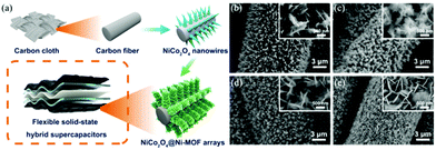 | ||
| Fig. 4 (a) Schematic illustration of the synthesis of NiCo2O4@Ni-MOF on CF. (b–e) SEM images of NiCo2O4@Ni-MOF synthesized at 3, 6, 12, and 24 h for MOF growth, respectively. Reprinted with permission from ref. 58, Copyright 2019, American Chemical Society. | ||
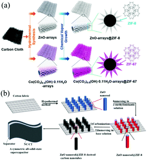 | ||
| Fig. 5 (a) Scheme showing the synthetic process of ZnO@ZIF-8 and Co(CO3)0.5(OH)·0.11H2O@ZIF-67 on CC. Reprinted with permission from ref. 63, Copyright 2018, American Chemical Society. (b) Schematic illustration showing the fabrication of ZnO@ZIF-8 derived nanotubes. Reprinted with permission from ref. 64, Copyright 2018, Elsevier. | ||
The above studies show that self-supported TMO/MOF hybrid arrays can be constructed by the growth of MOFs on TMO or partial transformation of TMOs into MOFs, and the combination of MOFs with TMOs is an effective way to further improve the energy storage performance of MOF-based electrodes. However, there are many fundamental and technical challenges to be overcome before MOF composites can meet the requirements of SC devices. A better understanding of the MOF composite mounting mechanism is highly desirable to guide and explore the incorporation of other electrode materials such as carbon, conductive polymers and metal sulfides with MOFs to form hybrid arrays.
3 Self-supported nano-structures derived from MOF templates
Apart from being directly used as electrode materials, MOFs have recently been extensively explored as a promising template/precursor for constructing electrode materials. The thermal transformation of MOFs yields a variety of nanostructured materials, including porous carbon, metal oxides and metal sulfides. These MOF derivatives are characterized by a high specific surface area, permanent pores and controlled functionality, which make them suitable as electrode materials. This section will give an overview on recent advances in self-supported nanostructures derived from MOF templates, and the use of them in SCs.3.1 Direct conversion of MOF nanostructures
![[thin space (1/6-em)]](https://www.rsc.org/images/entities/char_2009.gif) 000 cycles at 10 A g−1. This work provided a new way to design MOF-based porous carbon films as binder-free electrodes for high-performance energy storage devices. Zhang et al. prepared a hydrophilic, porous and heteroatom-doped carbon foam by annealing the ZIF-67 precursor followed by surface modification.70 An array of triangular ZIF-67 with an average thickness of 120 nm was first grown on CC (Fig. 6a). ZIF-67 contains a high carbon content and can be directly converted to a carbon–metal porous material without secondary carbon precursors. After calcination under an inert atmosphere, 3D graphitic foam-like carbon was formed with a large number of visible macropores (10–30 nm), as shown in Fig. 6b. The optimized CC supported porous carbon foam (RPCF/CC) exhibited a maximum capacitance of 1.049 F cm−2 at a current density of 12 mA cm−2 and a capacitance retention of 98.4% after 6000 charge/discharge cycles at 15 mA cm−2. The ASC device assembled by coupling the carbon foam with an MnO2/CC cathode in a neutral Na2SO4 aqueous electrolyte could provide an energy density of up to 10.1 mW h cm−3. A similar work was performed by Song et al., who synthesized a Co-MOF nanocuboid on CC, and then transformed the Co-MOF into nanoporous N-doped carbon nanocubes encapsulated with cobalt oxide and Co metal (Co-ZIF-450/CC) by annealing the Co-MOF under an N2 atmosphere (Fig. 6c).71 The highly conductive Co metal and N-doped carbon networks facilitated the electron transport. The nanopores acted as a reservoir for the electrolyte, reducing the diffusion distance of ions from the electrolyte to the electrode surface. Benefiting from these factors, the prepared electrode displayed a high areal capacitance (1.177 F cm−2 at 1 mA cm−2) and outstanding cycling stability (94% capacitance retention after 20
000 cycles at 10 A g−1. This work provided a new way to design MOF-based porous carbon films as binder-free electrodes for high-performance energy storage devices. Zhang et al. prepared a hydrophilic, porous and heteroatom-doped carbon foam by annealing the ZIF-67 precursor followed by surface modification.70 An array of triangular ZIF-67 with an average thickness of 120 nm was first grown on CC (Fig. 6a). ZIF-67 contains a high carbon content and can be directly converted to a carbon–metal porous material without secondary carbon precursors. After calcination under an inert atmosphere, 3D graphitic foam-like carbon was formed with a large number of visible macropores (10–30 nm), as shown in Fig. 6b. The optimized CC supported porous carbon foam (RPCF/CC) exhibited a maximum capacitance of 1.049 F cm−2 at a current density of 12 mA cm−2 and a capacitance retention of 98.4% after 6000 charge/discharge cycles at 15 mA cm−2. The ASC device assembled by coupling the carbon foam with an MnO2/CC cathode in a neutral Na2SO4 aqueous electrolyte could provide an energy density of up to 10.1 mW h cm−3. A similar work was performed by Song et al., who synthesized a Co-MOF nanocuboid on CC, and then transformed the Co-MOF into nanoporous N-doped carbon nanocubes encapsulated with cobalt oxide and Co metal (Co-ZIF-450/CC) by annealing the Co-MOF under an N2 atmosphere (Fig. 6c).71 The highly conductive Co metal and N-doped carbon networks facilitated the electron transport. The nanopores acted as a reservoir for the electrolyte, reducing the diffusion distance of ions from the electrolyte to the electrode surface. Benefiting from these factors, the prepared electrode displayed a high areal capacitance (1.177 F cm−2 at 1 mA cm−2) and outstanding cycling stability (94% capacitance retention after 20![[thin space (1/6-em)]](https://www.rsc.org/images/entities/char_2009.gif) 000 cycles).
000 cycles).
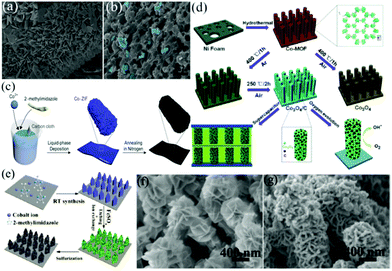 | ||
| Fig. 6 SEM images of (a) ZIF-67/CC and its derived (b) carbon foam. Reprinted with permission from ref. 70, Copyright 2019, Elsevier. (c) Schematic illustrating the synthesis of a cobalt-containing nanoporous N-doped carbon nanocuboid. Reprinted with permission from ref. 71, Copyright 2019, MDPI. (d) Schematic illustration of the synthesis of hybrid Co3O4/C electrodes for application in SCs and the oxygen evolution reaction. Reprinted with permission from ref. 72, Copyright 2016, Royal Society of Chemistry. (e) Schematic illustration of the fabrication of Fe–Co–S/NF, and the SEM images of (f) LDH@Co-MOF/NF and (g) Fe–Co–S/NF. Reprinted with permission from ref. 73, Copyright 2019, Elsevier. | ||
![[thin space (1/6-em)]](https://www.rsc.org/images/entities/char_2009.gif) :
:![[thin space (1/6-em)]](https://www.rsc.org/images/entities/char_2009.gif) 2) exhibited a high areal capacity of 1.1 mA h cm−2, corresponding to a high specific capacity of 358.1 mA h g−1 at a current density of 10 mA cm−2, which was superior to bimetallic Ni–Co–S NSAs.
2) exhibited a high areal capacity of 1.1 mA h cm−2, corresponding to a high specific capacity of 358.1 mA h g−1 at a current density of 10 mA cm−2, which was superior to bimetallic Ni–Co–S NSAs.
Diverse nanostructured electrode materials can be simply obtained by direct conversion of MOFs. The MOF derivative inherits the clear morphology of the parent MOF, retaining the open metal active sites and structural stability. It shows great potential in SCs. However, the single component electrode still cannot fulfill the requirements of high-performance SCs.
3.2 MOF derivatives as the scaffolds for anchoring secondary electrode materials
Metal oxides and metal sulfides, which have the advantages of low cost, high natural abundance and high theoretical capacity, are the most used faradaic electrode materials. However, the use of single metal oxide or metal sulfide nanoparticles as electrode materials still faces some inherent problems such as insufficient redox reactive sites, low electrical conductivity and poor cycling stability. Various feasible strategies have been proposed to address these obstacles. For example, some researchers have used MOF derivatives as a scaffold for anchoring secondary electrode materials to synthesize core–shell nanostructured materials with multiple functions to enhance the electrochemical performance. These core–shell nanostructures including nanospheres, nanoprisms and nanocubes can provide high active surface areas and short diffusion paths for ions and electrons. However, the fragile structure of the shell materials and the easy aggregation of the core limited their application as SC electrode materials.90–93 Growing self-supported nanoarrays of core–shell structured materials on conducting substrates is considered to be an effective strategy to address this challenge. For example, Han et al. firstly synthesized Co-MOF nanosheets on carbon cloth (CC) substrates by a solution method at room temperature. Next, Co3O4 nanosheets were obtained by calcining the Co-MOF template under an air atmosphere. Finally, Co3O4 nanosheets were used as a backbone to prepare the final petal-like CC/Co3O4@CoNi2S4 nanosheet arrays by an electrodeposition process (Fig. 7a).94 The electrode showed a specific capacity of 244.4 mA h g−1 at a current density of 1 A g−1 and an excellent rate capability of 81.3% at a current density of 16 A g−1. Tao et al. constructed a novel NiCo2O4 nanosheet decorated Co3O4 nanoarray on NF by using a leaf-like Co-MOF as a template (Fig. 7b).95 As a binder-free electrode for SCs, it displayed a specific capacity of 544.2 C g−1 at a current density of 1 A g−1, which was 9.3 times higher than that of the Co3O4 or NiCo2O4 electrode, demonstrating the advantages of self-supported core–shell nanoarrays. Sun et al. used a simple solution method to grow homogeneous Zn/Co-MOF nanosheet arrays directly on CC substrates.96 Subsequently, ZnCoS nanosheet arrays were obtained by calcination and a hydrothermal anion exchange reaction, and it was used as a scaffold for the deposition of Ni(OH)2 and VN, respectively. Ni(OH)2@ZnCoS and VN@ZnCoS were assembled into an ASC device, which exhibited an ultra-high energy density (75 W h kg−1 at a power density of 0.4 kW kg−1) and excellent cycling stability (a capacitance retention rate of 92% after 10![[thin space (1/6-em)]](https://www.rsc.org/images/entities/char_2009.gif) 000 cycles).
000 cycles).
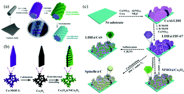 | ||
| Fig. 7 (a) Schematic illustrating the synthesis procedure of CC/Co3O4@CoNi2S4. Reprinted with permission from ref. 94, Copyright 2020, Royal Society of Chemistry. (b) Schematic illustration of the fabrication of Co3O4@NiCo2O4 nanoarrays. Reprinted with permission from ref. 95, Copyright 2019, Royal Society of Chemistry. (c) Schematic illustration of the fabrication of hierarchically structured MMO@Co3O4, spinelle@C and LDH@CoS derived from CoAl-LDH@ZIF-67. Reprinted with permission from ref. 97, Copyright 2016, Royal Society of Chemistry. | ||
The above results indicate that the combination of MOF-derived core–shell structured nanomaterials and conducting substrates can improve the electrochemical performance of single component electrode materials. This strategy can be adopted to construct various core–shell nanoarrays on conductive substrates. However, to achieve a synergetic effect of different electrode materials, the type of electrode materials, growth sequence and template morphology should be taken into full consideration for a better understanding of the assembly of the core–shell structure.
3.3 Decorating MOF derivatives on micro-/nanoarrays
The elaborate design and fabrication of hierarchically integrated electrodes by anchoring MOF derivatives on highly conductive active materials have attracted increasing interest in recent years. This will compensate for the inherent defects of the MOF derivatives, giving rise to improved specific capacitance and cycling stability. For example, Dou et al. prepared CoAl-LDH@ZIF-67 by the in situ growth of ZIF-67 on CoAl-LDH nanoflakes fabricated on NF.97 Subsequently, LDH@ZIF-67 was utilized as a template/precursor to obtain mixed metal oxides (MMO)@Co3O4, spinelle@C and LDH@CoS by oxidization, carbonization and sulfidation, respectively (Fig. 7c). The resulting hierarchical derivatives showed enhanced electrochemical properties due to the strong electronic coupling of heterostructures and the synergistic effect between different components. Fei et al. designed and synthesized sugarloaf-like multicomponent yolk–shell Ni–Mo–Co–S nanocage arrays (NCAs) on NF by a simple MOF engagement strategy (Fig. 8a–e).98 ZIF-67 nanocrystals were first deposited on NiMoO4·xH2O nanorods to form core–sheath NiMoO4·xH2O@ZIF-67, and NiMoO4·xH2O@ZIF-67 was transformed into hollow NiMoO4·xH2O@Ni–Co–S NCAs (Fig. 8g) and yolk–shell Ni–Mo–Co–S NCAs (Fig. 8h) after sulfidation with low and large dosages of TAA, respectively. Benefiting from the interesting structural and compositional advantages, the yolk–shell NiMoCo–S NCAS/NF binderless electrode exhibited an extremely high area capacity of 1.96 mA h cm−2 at a current density of 5 mA cm−2. Dai et al. prepared a hollow S-doped Co3O4 sheath on CoO nanowires by a two-step synthesis including the surface etching of CoO nanowires for the simultaneous in situ growth of well-aligned ZIF-67 and subsequent sulfidation.99 The synergistic effect between conductive CC and the hollow ordered nanoarrays ensured efficient mass and electron transport. Thus, the core–shell nanoarrays displayed a high areal capacitance of 1.013 F cm−2 at 1 mA cm−2. Tang et al. perfectly decorated MOF-derived Zn0.76Co0.24S nanoparticle@C on Zn0.76Co0.24S nanosheet arrays (Zn0.76Co0.24S CSNSAs).100 As a free-standing electrode material for SCs, it provided a high specific capacity of 1202 C g−1 at a current density of 1 A g−1.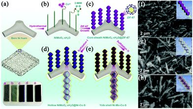 | ||
| Fig. 8 (a–e) Schematic illustrations of the synthesis of yolk–shell Ni–Mo–Co–S NCAs on NF. SEM images of (f) NiMoO4·xH2O@ZIF-67, (g) hollow NiMoO4·xH2O@Ni–Co–S NCAs and (h) yolk–shell Ni–Mo–Co–S NCAs. Reprinted with permission from ref. 98, Copyright 2020, Elsevier. | ||
Anchoring MOF derivatives on highly conductive active materials can significantly improve the electronic conductivity of electrodes. Besides, the hierarchical structure provides a large specific surface area and also prevents the aggregation of MOF derivatives. Thus, boosted electrochemical performance is realized.
4 Conclusions and perspectives
This review summarizes the recent advances in self-supported MOF-based nanostructures including pristine MOFs, MOF composites and MOF derivative arrays as binder-free electrodes for SCs, and the synthesis strategy of these nanostructures is overviewed. The advantages of self-supported MOF-based nanostructures as electrodes for SCs, such as a simplified electrode preparation process, enhanced electronic conductivity and largely exposed electroactive sites are highlighted. However, there are still a number of issues and challenges need to be addressed for practical applications. First, in order to produce practical devices, the mass loading of the electroactive materials on a current collector needs to exceed 10 mg cm−2. However, many self-supported MOF-based electrodes have a mass loading of only a few tens to hundreds of micrograms, and the electroactive materials are not uniformly distributed. Second, although MOF-based nanostructures show high specific capacitance in three-electrode systems, the assembled two-electrode cell usually displays moderate energy storage properties due to the mismatching electrochemical performance between the positive and negative electrodes. In this regard, energy storage devices with both electrodes using self-supported MOF-based nanostructures derived from one single precursor are more advantageous, since the two electrodes share similar properties. Moreover, the assembly of the devices should be intensively studied and optimized. Finally, the choice of MOF precursors for self-supported electrodes is mainly limited to a few MOFs, which means that the application potential of other MOFs has not yet been explored. Therefore, great works from MOF crystal design to electrode preparation and device assembly are needed to obtain the desirable electrochemical performance. Impressively, MOF-templated hierarchical core–shell nanoarrays have recently attracted much attention. In such core–shell nanostructures, the disadvantages of individual components are compensated and a synergetic effect between different components is realized. This strategy offers an opportunity to manipulate the overall performance of electrode materials.In conclusion, self-supported MOF-based nanostructures with exciting energy storage properties have emerged as new generation binder-free electrodes for SCs. We hope that this review can provide an overview on this highly exciting field, and will stimulate more explorations on this topic promoting the application of MOF-based electrode materials in high-performance electrochemical energy storage devices.
Author contributions
Xueyan Zhao: writing – the original draft. Kai Tao: conceptualization, supervision and writing – review and editing. Lei Han: supervision and writing – review and editing.Conflicts of interest
There are no conflicts to declare.Acknowledgements
This work was financially supported by the Zhejiang Provincial Natural Science Foundation of China (LY20E020005) and the National Science Foundation of China (5157227 and 221971131).References
- K. Zhang, K. O. Kirlikovali, L. Quyet Van, Z. Jin, R. S. Varma, H. W. Jang, O. K. Farha and M. Shokouhimehr, ACS Appl. Nano Mater., 2020, 3, 3964–3990 CrossRef CAS.
- S. Tajik, H. Beitollahi, F. G. Nejad, K. O. Kirlikovali, L. Quyet Van, H. W. Jang, R. S. Varma, O. K. Farha and M. Shokouhimehr, Cryst. Growth Des., 2020, 20, 7034–7064 CrossRef CAS.
- A. E. Baumann, D. A. Burns, B. Liu and V. S. Thoi, Commun. Chem., 2019, 2, 86 CrossRef.
- H. B. Wu and X. W. D. Lou, Sci. Adv., 2017, 3, eaap9252 CrossRef PubMed.
- S. Liu, L. Kang, J. Zhang, S. C. Jun and Y. Yamauchi, ACS Energy Lett., 2021, 6, 4127–4154 CrossRef CAS.
- S. Liu, L. Kang, J. Henzie, J. Zhang, J. Ha, M. A. Amin, M. S. A. Hossain, S. C. Jun and Y. Yamauchi, ACS Nano, 2021, 15, 18931–18973 CrossRef CAS PubMed.
- J. Liao, C. Chen, Q. Hu, Y. Du, Y. He, Y. Xu, Z. Zhang and X. Zhou, Angew. Chem., Int. Ed., 2021, 60, 25575–25582 CrossRef CAS PubMed.
- Y. Du, Z. Yi, B. Chen, J. Xu, Z. Zhang, J. Bao and X. Zhou, J. Energy Chem., 2022, 66, 413–421 CrossRef.
- X. Xu, L. Si, X. Zhou, F. Tu, X. Zhu and J. Bao, J. Power Sources, 2017, 349, 37–44 CrossRef CAS.
- R. R. Salunkhe, Y. V. Kaneti and Y. Yamauchi, ACS Nano, 2017, 11, 5293–5308 CrossRef CAS PubMed.
- Q. Yang, Acta Phys. Chim. Sin., 2020, 36, 1910030 Search PubMed.
- H. Zhao, L. Liu, R. Vellacheri and Y. Lei, Adv. Sci., 2017, 4, 1700188 CrossRef PubMed.
- D. Sheberla, J. C. Bachman, J. S. Elias, C.-J. Sun, Y. Shao-Horn and M. Dinca, Nat. Mater., 2017, 16, 220–224 CrossRef CAS PubMed.
- W. Xia, A. Mahmood, R. Q. Zou and Q. Xu, Energy Environ. Sci., 2015, 8, 1837–1866 RSC.
- X. Y. Zhao, Q. X. Ma, K. Tao and L. Han, ACS Appl. Energy Mater., 2021, 4, 4199–4207 CrossRef CAS.
- A. Saad, S. Biswas, E. Gkaniatsou, C. Sicard, E. Dumas, N. Menguy and N. Steunou, Chem. Mater., 2021, 33, 5825–5849 CrossRef CAS.
- S. Dang, Q.-L. Zhu and Q. Xu, Nat. Rev. Mater., 2018, 3, 17075 CrossRef CAS.
- L. Meng, B. Yu and Y. Qin, Commun. Chem., 2021, 4, 82 CrossRef CAS.
- H. B. Zhang, J. W. Nai, L. Yu and X. W. Lou, Joule, 2017, 1, 77–107 CrossRef CAS.
- B. Y. Guan, X. Y. Yu, H. B. Wu and X. W. Lou, Adv. Mater., 2017, 29, 1703614 CrossRef PubMed.
- T. Yue, C. Xia, X. Liu, Z. Wang, K. Qi and B. Y. Xia, ChemElectroChem, 2021, 8, 1021–1034 CrossRef CAS.
- J. Wang, Q. Zhong, Y. Q. Zeng, D. Y. Cheng, Y. H. Xiong and Y. F. Bu, J. Colloid Interface Sci., 2019, 555, 42–52 CrossRef CAS PubMed.
- Y. Liu, N. Xin, Q. Yang and W. Shi, J. Colloid Interface Sci., 2021, 583, 288–298 CrossRef CAS PubMed.
- X. Han, K. Tao, D. Wang and L. Han, Nanoscale, 2018, 10, 2735–2741 RSC.
- L. Feng, X. Han, X. R. Su, B. C. Pang, Y. L. Luo, F. Hu, M. J. Zhou, K. Tao and Y. Y. Xia, J. Alloys Compd., 2018, 765, 512–519 CrossRef CAS.
- B. Singh and A. Indra, Chem. – Asian J., 2020, 15, 607–623 CrossRef CAS PubMed.
- G. Cai, W. Zhang, L. Jiao, S.-H. Yu and H.-L. Jiang, Chem, 2017, 2, 791–802 CAS.
- H. Liang, A. Yao, X. Jiao, C. Li and D. Chen, ACS Appl. Mater. Interfaces, 2018, 10, 20396–20403 CrossRef CAS PubMed.
- Y. Wang, A. Wang, Z. Xue, L. Wang, X. Li and G. Wang, J. Mater. Chem. A, 2021, 9, 22597–22602 RSC.
- B. Singh, A. Singh, A. Yadav and A. Indra, Coord. Chem. Rev., 2021, 447, 214144 CrossRef CAS.
- L. Wan and P. Wang, Int. J. Hydrogen Energy, 2021, 46, 8356–8376 CrossRef CAS.
- Q. Cheng, K. Tao, X. Han, Y. Yang, Z. Yang, Q. Ma and L. Han, Dalton Trans., 2019, 48, 4119–4123 RSC.
- W. W. Li, X. Y. Zhao, Q. Bi, Q. X. Ma, L. Han and K. Tao, Dalton Trans., 2021, 50, 11701–11710 RSC.
- Y. Xue, G. Zhao, R. Yang, F. Chu, J. Chen, L. Wang and X. Huang, Nanoscale, 2021, 13, 3911–3936 RSC.
- A. Dhakshinamoorthy, A. M. Asiri and H. Garcia, Adv. Mater., 2019, 31, 1900617 CrossRef CAS PubMed.
- Y. Xu, Q. Li, H. Xue and H. Pang, Coord. Chem. Rev., 2018, 376, 292–318 CrossRef CAS.
- Y. Xue, S. Zheng, H. Xue and H. Pang, J. Mater. Chem. A, 2019, 7, 7301–7327 RSC.
- W. Liu, R. Yin, X. Xu, L. Zhang, W. Shi and X. Cao, Adv. Sci., 2019, 6, 1802373 CrossRef PubMed.
- W. Xia, A. Mahmood, R. Zou and Q. Xu, Energy Environ. Sci., 2015, 8, 1837–1866 RSC.
- W.-H. Li, K. Ding, H.-R. Tian, M.-S. Yao, B. Nath, W.-H. Deng, Y. Wang and G. Xu, Adv. Funct. Mater., 2017, 27, 1702067 CrossRef.
- M. Zhao, Q. Lu, Q. Ma and H. Zhang, Small Methods, 2017, 1, 1600030 CrossRef.
- G. Chakraborty, I.-H. Park, R. Medishetty and J. J. Vittal, Chem. Rev., 2021, 121, 3751–3891 CrossRef CAS PubMed.
- L. Yao, J. Lin, H. Yang, Q. Wu, D. Wang, X. Li, L. Deng and Z. Zheng, Nanoscale, 2019, 11, 11086–11092 RSC.
- J. Ma, J. Li, R. Guo, H. Xu, F. Shi, L. Dang, Z. Liu, J. Sun and Z. Lei, J. Power Sources, 2019, 428, 124–130 CrossRef CAS.
- F. Zhang, J. L. Zhang, J. J. Ma, X. Y. Zhao, Y. Y. Li and R. Q. Li, J. Colloid Interface Sci., 2021, 593, 32–40 CrossRef CAS PubMed.
- J. Yang, P. Xiong, C. Zheng, H. Qiu and M. Wei, J. Mater. Chem. A, 2014, 2, 16640–16644 RSC.
- N. Raza, T. Kumar, V. Singh and K.-H. Kim, Coord. Chem. Rev., 2021, 430, 213660 CrossRef CAS.
- J. Wang, Q. Zhong, Y. Zeng, D. Cheng, Y. Xiong and Y. Bu, J. Colloid Interface Sci., 2019, 555, 42–52 CrossRef CAS PubMed.
- F. Ren, Y. Ji, F. Chen, Y. Qian, J. Tian and J. Wang, Mater. Chem. Front., 2021, 5, 7333–7342 RSC.
- Y. Chen, N. Wang, W. Hu and S. Komarneni, J. Porous Mater., 2019, 26, 921–929 CrossRef CAS.
- T. Deng, Y. Lu, W. Zhang, M. Sui, X. Shi, D. Wang and W. Zheng, Adv. Energy Mater., 2018, 8, 1702294 CrossRef.
- J. Zhang, Z. Wang, T. Deng and W. Zhang, Nanotechnology, 2021, 32, 195404 CrossRef CAS PubMed.
- S. Xu, R. Liu, X. Shi, Y. Ma, M. Hong, X. Chen, T. Wang, F. Li, N. Hu and Z. Yang, Electrochim. Acta, 2020, 342, 136124 CrossRef CAS.
- X. M. Cao and Z. B. Han, Chem. Commun., 2019, 55, 1746–1749 RSC.
- B. Chen, L. Xu, Z. Xie and W.-Y. Wong, EcoMat, 2021, 3, e12106 CAS.
- T. Li, Y. Bai, Y. Wang, H. Xu and H. Jin, Coord. Chem. Rev., 2020, 410, 213221 CrossRef CAS.
- Q. Bi, Q. Ma, K. Tao and L. Han, Dalton Trans., 2021, 50, 8179–8188 RSC.
- G. Li, H. R. Cai, X. L. Li, J. Zhang, D. S. Zhang, Y. F. Yang and J. Xiong, ACS Appl. Mater. Interfaces, 2019, 11, 37675–37684 CrossRef CAS PubMed.
- F. Yang, H. Guo, Y. Chen, M. Xu, W. Yang, M. Wang, M. Yang, J. Zhang, L. Sun, T. Zhang and W. Yang, Chem. – Eur. J., 2021, 27, 14478–14488 CrossRef CAS PubMed.
- X. Hu, S. Liu, Y. Wang, X. Huang, J. Jiang, H. Cong, H. Lin and S. Han, J. Colloid Interface Sci., 2021, 600, 72–82 CrossRef CAS PubMed.
- X.-M. Cao and Z.-B. Han, Chem. Commun., 2019, 55, 1746–1749 RSC.
- Y. V. Kaneti, S. Dutta, M. S. A. Hossain, M. J. A. Shiddiky, K. L. Tung, F. K. Shieh, C. K. Tsung, K. C. W. Wu and Y. Yamauchi, Adv. Mater., 2017, 29, 1700213 CrossRef PubMed.
- C. Young, J. Wang, J. Kim, Y. Sugahara, J. Henzie and Y. Yamauchi, Chem. Mater., 2018, 30, 3379–3386 CrossRef CAS.
- Y.-N. Liu, H.-T. Wang, X.-H. Kang, Y.-F. Wang, S.-Y. Yang and S.-W. Bian, J. Power Sources, 2018, 402, 413–421 CrossRef CAS.
- B. Liu, H. Shioyama, T. Akita and Q. Xu, J. Am. Chem. Soc., 2008, 130, 5390–5391 CrossRef CAS PubMed.
- Y. V. Kaneti, J. Tang, R. R. Salunkhe, X. Jiang, A. Yu, K. C. Wu and Y. Yamauchi, Adv. Mater., 2017, 29, 1604898 CrossRef PubMed.
- M. H. Yap, K. L. Fow and G. Z. Chen, Green Energy Environ., 2017, 2, 218–245 CrossRef.
- X. Cao, C. Tan, M. Sindoro and H. Zhang, Chem. Soc. Rev., 2017, 46, 2660–2677 RSC.
- Y. Liu, G. Li, Y. Guo, Y. Ying and X. Peng, ACS Appl. Mater. Interfaces, 2017, 9, 14043–14050 CrossRef CAS PubMed.
- J. Zhang, W. Li, T. Ahmed Shifa, J. Sun, C. Jia, Y. Zhao and Y. Cui, J. Power Sources, 2019, 439, 227066 CrossRef CAS.
- Y. Song, M. Zhang, T. Liu, T. Li, D. Guo and X.-X. Liu, Nanomaterials, 2019, 9, 1110 CrossRef CAS PubMed.
- C. Zhang, J. Xiao, X. Lv, L. Qian, S. Yuan, S. Wang and P. Lei, J. Mater. Chem. A, 2016, 4, 16516–16523 RSC.
- K. Le, M. Gao, W. Liu, J. Liu, Z. Wang, F. Wang, V. Murugadoss, S. Wu, T. Ding and Z. Guo, Electrochim. Acta, 2019, 323, 134826 CrossRef CAS.
- S. Wu, J. Liu, H. Wang and H. Yan, Int. J. Energy Res., 2019, 43, 697–716 CrossRef CAS.
- X.-C. Xie, K.-J. Huang and X. Wu, J. Mater. Chem. A, 2018, 6, 6754–6771 RSC.
- Y. Li, Y. Xu, W. Yang, W. Shen, H. Xue and H. Pang, Small, 2018, 14, 1704435 CrossRef PubMed.
- S. Liu, L. Kang, J. Zhang, E. Jung, S. Lee and S. C. Jun, Energy Storage Mater., 2020, 32, 167–177 CrossRef.
- S. Liu, L. Kang, J. Hu, E. Jung, J. Zhang, S. C. Jun and Y. Yamauchi, ACS Energy Lett., 2021, 6, 3011–3019 CrossRef CAS.
- X. Zhang, J. Luo, P. Tang, X. Ye, X. Peng, H. Tang, S.-G. Sun and J. Fransaer, Nano Energy, 2017, 31, 311–321 CrossRef CAS.
- D. Kong, Y. Wang, S. Huang, J. Hu, Y. V. Lim, B. Liu, S. Fan, Y. Shi and H. Y. Yang, Energy Storage Mater., 2019, 23, 653–663 CrossRef.
- S. Li, Y. Duan, Y. Teng, N. Fan and Y. Huo, Appl. Surf. Sci., 2019, 478, 247–254 CrossRef CAS.
- J. Acharya, B. Pant, G. P. Ojha, H. S. Kong and M. Park, J. Colloid Interface Sci., 2021, 602, 573–589 CrossRef CAS PubMed.
- W. Zhan, L. Sun and X. Han, Nano–Micro Lett., 2019, 11, 1 CrossRef CAS PubMed.
- J. M. Gonçalves, P. R. Martins, D. P. Rocha, T. A. Matias, M. S. S. Julião, R. A. A. Munoz and L. Angnes, J. Mater. Chem. C, 2021, 9, 8718–8745 RSC.
- T. Chen, X. Liu, L. Niu, Y. Gong, C. Li, S. Xu and L. Pan, Inorg. Chem. Front., 2020, 7, 567–582 RSC.
- J. Ma, W. Li, X. Zhang, Y. Cheng and F. Zhang, Appl. Surf. Sci., 2020, 507, 145074 CrossRef CAS.
- K. Tao, X. Han, Q. Cheng, Y. Yang, Z. Yang, Q. Ma and L. Han, Chem. – Eur. J., 2018, 24, 12584–12591 CrossRef CAS PubMed.
- L. Zheng, J. Song, X. Ye, Y. Wang, X. Shi and H. Zheng, Nanoscale, 2020, 12, 13811–13821 RSC.
- Y. Huang, L. Quan, T. Liu, Q. Chen, D. Cai and H. Zhan, Nanoscale, 2018, 10, 14171–14181 RSC.
- K.-C. Ho and L.-Y. Lin, J. Mater. Chem. A, 2019, 7, 3516–3530 RSC.
- H. P. Feng, L. Tang, G. M. Zeng, Y. Zhou, Y. C. Deng, X. Ren, B. Song, C. Liang, M. Y. Wei and J. F. Yu, Adv. Colloid Interface Sci., 2019, 267, 26–46 CrossRef CAS PubMed.
- L.-b. Jiang, X.-z. Yuan, J. Liang, J. Zhang, H. Wang and G.-m. Zeng, J. Power Sources, 2016, 331, 408–425 CrossRef CAS.
- B. Zhang, F. Kang, J.-M. Tarascon and J.-K. Kim, Prog. Mater. Sci., 2016, 76, 319–380 CrossRef CAS.
- D. Han, J. Wei, Y. Zhao, Y. Shen, Y. Pan, Y. Wei and L. Mao, Inorg. Chem. Front., 2020, 7, 1428–1436 RSC.
- K. Tao, Y. Yang, C. Yang, Q. Ma and L. Han, Dalton Trans., 2019, 48, 14156–14163 RSC.
- W. Sun, Y. Du, G. Wu, G. Gao, H. Zhu, J. Shen, K. Zhang and G. Cao, J. Mater. Chem. A, 2019, 7, 7138–7150 RSC.
- Y. Dou, J. Zhou, F. Yang, M.-J. Zhao, Z. Nie and J.-R. Li, J. Mater. Chem. A, 2016, 4, 12526–12534 RSC.
- B. Fei, Z. Yao, D. Cai, J. Si, Q. Wang, Q. Chen, B. Sa, K. Peng and H. Zhan, Energy Storage Mater., 2020, 25, 105–113 CrossRef.
- S. Dai, Y. Yuan, J. Yu, J. Tang, J. Zhou and W. Tang, Nanoscale, 2018, 10, 15454–15461 RSC.
- Q. Tang, L. Ma, F. Yan, M. Gan, X. Li, F. Cao, M. Ye, Y. Zhai and Y. Zhou, Synth. Met., 2019, 250, 136–145 CrossRef CAS.
| This journal is © The Royal Society of Chemistry 2022 |

