 Open Access Article
Core@shell Sb@Sb2O3 nanoparticles anchored on 3D nitrogen-doped carbon nanosheets as advanced anode materials for Li-ion batteries†
Xian
Chen‡
,
Liang
Wang‡
,
Feng
Ma
 ,
Tanyuan
Wang
 ,
Jiantao
Han
 ,
Yunhui
Huang
 and
Qing
Li
 *
*
State Key Laboratory of Material Processing and Die & Mould Technology, School of Materials Science and Engineering, Huazhong University of Science and Technology, Wuhan 430074, China. E-mail: qing_li@hust.edu.cn
First published on 12th October 2020
Abstract
Antimony (Sb) based materials are regarded as promising anode materials for Li-ion batteries (LIBs) because of the high capacity, appropriate working potential, and earth abundance of antimony. However, the quick capacity decay due to the huge volume expansion during the cycling process seriously hinders its practical applications. Here, a nanocomposite of core@shell Sb@Sb2O3 particles anchored on 3D porous nitrogen-doped carbon (3DNC) nanosheets is synthesized by freeze drying and sintering in a reducing atmosphere. Structural characterization shows that the developed Sb@Sb2O3/3DNC electrode has a high surface area (839.8 m2 g−1) and unique Sb–O–C bonding, both contributing to the excellent electrochemical performance. The initial charge and discharge specific capacities of the Sb@ Sb2O3/3DNC anode in LIB tests are 1109 mA h g−1 and 1810 mA h g−1, respectively. Also, it shows a charge capacity of 696.9 mA h g−1 after 500 cycles at 1 A g−1 and 458 mA h g−1 at a current density of 5 A g−1. Moreover, the assembled Sb@Sb2O3/3DNC‖LiNi0.6Co0.2Mn0.2O2 battery exhibits a discharge capacity of more than 100 mA h g−1 after 25 cycles at 100 mA g−1. The synthetic method can be extended to obtain other nanocomposites of metal and carbon materials for high-performance energy storage devices.
Introduction
Lithium-ion batteries (LIBs) have been regarded as the most viable energy storage technology for portable electronic devices and electric vehicles in the past few decades.1–3 Nevertheless, the applications of large-scale energy storage systems and smart grids still require new-generation LIBs with higher energy density, faster rate capability, and longer cycle life.4 The currently used commercial graphite anode cannot meet the growing demand due to its low theoretical capacity and poor rate capability.5,6 Recently, alloy-type anodes and their compounds have been studied as alternative anodes for LIBs because of their higher theoretical capacities.7,8 Among metal-based anode materials, antimony (Sb) and its compounds exhibit great potential as anode materials due to their high theoretical capacity of 660 mA h g−1, low polarization (∼0.2 V), and suitable working voltage (0.8–0.9 V vs. Li+/Li).Unfortunately, the relatively low electron-conductivity of Sb and large volume expansion (150% from Sb to Li3Sb) upon the charge/discharge process lead to particle pulverization and loss of electrical contact along with rapid capacity decay, which hinder the practical applications of Sb-based materials in LIBs.9–13
In order to solve these issues, various efforts such as engineering the electrode structure and introducing buffer layers into Sb-based anodes have been made.14–16 For instance, Sb2O3/reduced graphene oxide (Sb2O3/rGO) nanocomposites exhibited improved electrochemical performance as anodes in both LIBs and sodium ion batteries (SIBs).17 A 3D nest-shaped Sb2O3/rGO composite was reported by wet chemistry as an anode material for LIBs and delivered a high capacity of 562 mA h g−1 after 100 charge/discharge cycles, corresponding to 63% retention of initial capacity.18 Nitrogen-doped reduced graphene oxide-bonded Sb nanoparticles (Sb/N-rGO) were synthesized by ball-milling nitrogen/Sb precursors and subsequent pyrolysis treatment, which showed a reversible capacity of 304.8 mA h g−1 at 5 A g−1 and 90.7% capacity retention after 500 cycles at 0.1 A g−1 for SIBs.19 Based on these previous studies, rationally designed Sb/Sb2O3 nanostructures combined with graphene buffer layers can significantly improve the electrochemical performance of Sb-based materials. However, Sb or Sb2O3 nanoparticles tend to aggregate during high-temperature pyrolysis and the interaction between the metal and the buffer layers is quite weak, leaving room for further development of Sb-based electrodes for electrochemical energy storage.
Here, with the help of the complexation between sodium alginate (SA) and Sb3+, core@shell Sb@Sb2O3 particles anchored on 3D porous nitrogen-doped carbon nanosheets (Sb@Sb2O3/3DNC) are developed and employed as anode materials for LIBs. The Sb@ Sb2O3 nanoparticles (∼30 nm in diameter) are uniformly distributed on the 3D N-doped carbon nanosheets due to the SA–Sb3+ complexation, which strongly stabilizes Sb against agglomeration during pyrolysis. The generated Sb–O–C chemical bonds could facilitate electron transformation between Sb@Sb2O3 and the carbon matrix, and the abundant void spaces of the 3D continuous conducting network could accommodate the volumetric expansion of Sb@Sb2O3 during Li-ion insertion/extraction. As a result, the developed Sb@Sb2O3/3DNC is endowed with excellent electrochemical performance in LIBs, showing a charge capacity of 696.9 mA h g−1 after 500 cycles at 1 A g−1 and 458 mA h g−1 at 5 A g−1, which outperforms most of the reported Sb-based LIB anodes.17,18,20–22
Experimental
Material preparation
![[thin space (1/6-em)]](https://www.rsc.org/images/entities/char_2009.gif) :
:![[thin space (1/6-em)]](https://www.rsc.org/images/entities/char_2009.gif) 3
3![[thin space (1/6-em)]](https://www.rsc.org/images/entities/char_2009.gif) :
:![[thin space (1/6-em)]](https://www.rsc.org/images/entities/char_2009.gif) 1). By tuning the added amount of SA, Sb–C–N–1–2–1 and Sb–C–N–1–4–1 control samples can be prepared. For example, using 2 mmol SbCl3, 4 mmol SA and 131 μL cyanamide leads to Sb–C–N–1–2–1, while 2 mmol SbCl3, 8 mmol SA, and 131 μL cyanamide leads to Sb–C–N–1–4–1. Synthesis of Sb@Sb2O3/C and NC: N-free (denoted as Sb@Sb2O3/C) and metal-free (denoted as NC) control samples were obtained by a similar method without adding cyanamide and SbCl3, respectively.
1). By tuning the added amount of SA, Sb–C–N–1–2–1 and Sb–C–N–1–4–1 control samples can be prepared. For example, using 2 mmol SbCl3, 4 mmol SA and 131 μL cyanamide leads to Sb–C–N–1–2–1, while 2 mmol SbCl3, 8 mmol SA, and 131 μL cyanamide leads to Sb–C–N–1–4–1. Synthesis of Sb@Sb2O3/C and NC: N-free (denoted as Sb@Sb2O3/C) and metal-free (denoted as NC) control samples were obtained by a similar method without adding cyanamide and SbCl3, respectively.
Characterization
X-ray diffraction (XRD, X'Pert3 powder) with Cu-Kα radiation was performed to identify the crystal structures of the samples in the 2θ range from 10 to 80° with a step size of 0.01° and a count time of 4 s. Scanning electron microscopy (SEM, FEI, Sirion 200), transmission electron microscopy (TEM, FEI, Tecnai G2 20) and high resolution TEM (HRTEM, FEI, Tecnai G2 F30) were used to analyze the morphology and microstructure of the materials. Thermogravimetric analysis (TGA) was conducted on a TGA8000 analyzer at a heating rate of 10 °C min−1 from 25 to 600 °C in air. Adsorption isotherms and surface area were determined by Brunauer–Emmett–Teller (BET) measurements using an ASAP-2020 surface area analyzer. X-ray photoelectron spectroscopy (XPS) measurements were conducted using an AXIS-ULTRA DLD-600 W spectrometer with a monochromatic Al Mgα X-ray source. The binding energy for each spectrum was calibrated using the C 1s peak (285 eV) as the reference.Electrochemical testing
Electrochemical tests were performed using 2032 coin cells with lithium metal as the anode. The working electrodes were prepared by dispersing 80 wt% active materials (Sb@Sb2O3/3DNC and its controls), 10 wt% conducting agent (carbon black), and 10 wt% binder carboxymethylcellulose sodium (CMC, Aldrich) in DI water by magnetically stirring for 4 h. The obtained slurry was coated on current collectors (copper foil), roll-pressed, then dried at 100 °C for 12 h in a vacuum oven. The loadings of the active materials were about 0.5 and 1.5 mg cm−2. CR2032 coin-type cells were assembled in an argon-filled glove box by using 1.0 M LiPF6 dissolved in a mixture of ethylene carbonate (EC) and dimethyl carbonate (DMC) (1![[thin space (1/6-em)]](https://www.rsc.org/images/entities/char_2009.gif) :
:![[thin space (1/6-em)]](https://www.rsc.org/images/entities/char_2009.gif) 1 by volume) as an electrolyte and a Celgard-2400 microporous polypropylene membrane as the separator. The cycling and rate performance tests were conducted on a LAND system between 0.01 and 3.0 V at different current densities and all the specific capacities were calculated on the whole weight of active materials. All the characterizations and measurements were carried out at room temperature.
1 by volume) as an electrolyte and a Celgard-2400 microporous polypropylene membrane as the separator. The cycling and rate performance tests were conducted on a LAND system between 0.01 and 3.0 V at different current densities and all the specific capacities were calculated on the whole weight of active materials. All the characterizations and measurements were carried out at room temperature.
Results and discussion
Structural characterization of Sb@Sb2O3/3DNC
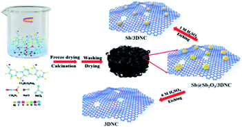
The procedures for synthesizing Sb@Sb2O3/3DNC, Sb/3DNC, and 3DNC samples are illustrated in Fig. 1. Briefly, appropriate amounts of SA, cyanamide, SbCl3, and NaCl were dissolved in DI water. Then the homogeneous solution was freeze-dried and calcined in 5% H2/Ar at 700 °C for 3 h. After removing NaCl, which serves as the pore-forming agent in the synthesis, the Sb@Sb2O3/3DNC sample is obtained. Further etching Sb@Sb2O3/3DNC using 1.0 M or 6.0 M H2SO4 could remove Sb2O3 shells or Sb@Sb2O3 nanoparticles to produce Sb/3DNC or 3DNC samples, respectively.The crystal structures of the prepared samples are characterized by XRD. As shown in Fig. 2a, all diffraction peaks of Sb@Sb2O3/3DNC and Sb@Sb2O3/C can be indexed to metallic Sb (JCPDS card no. 35-0732) and cubic senarmontite Sb2O3 (JCPDS card no. 43-1071). The peak intensity of Sb@Sb2O3/C is relatively weaker than that of Sb@Sb2O3/3DNC, suggesting the smaller particle size. As for the Sb/3DNC and 3DNC samples, it is obvious that Sb2O3 shells can be etched away by 1.0 M H2SO4 while Sb@Sb2O3 nanoparticles can be completely leached by 6.0 M H2SO4. The NC and 3DNC samples exhibit only a broad peak at ∼26° arising from the crystal plane of graphite, suggesting that the amorphous carbon is slightly graphitized under high temperature and no Sb-related particles exist in the samples. The percentage of carbon and Sb-based active materials was determined by TGA in air. As illustrated in Fig. 2b, the weight loss around 5% before 300 °C is due to the water evaporation of the materials. With temperature increasing, there is a sharp decrease of weight between 300 °C and 450 °C, which can be ascribed to the oxidation of carbon in air. The results show that the total mass loading of Sb@Sb2O3 is less than 9.41% for Sb@Sb2O3/3DNC. The relatively low content of Sb-based materials could reduce the effect of volume change and benefit the structural stability during charge/discharge processes.
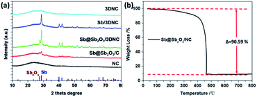 | ||
| Fig. 2 (a) XRD patterns of NC, Sb@Sb2O3/C, Sb@Sb2O3/3DNC, Sb/3DNC, and 3DNC. (b) TGA curve of the Sb@Sb2O3/3DNC sample in air. | ||
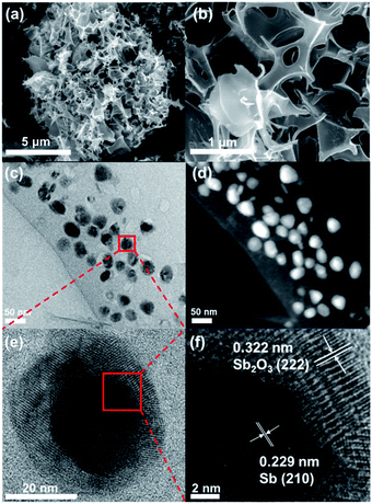
The morphology and structure of Sb@Sb2O3/3DNC were investigated by SEM and TEM. As shown in Fig. 3a and b, the material shows a continuous 3D porous network structure composed of nanosheets with the thickness of 12–20 nm. TEM images (Fig. 3c and d) indicate that Sb@Sb2O3 particles are uniformly distributed on the 3DNC nanosheets with an average size of ca. 30 nm likely due to the stabilization effect of SA–Sb3+ complexation. HRTEM was conducted to further investigate the micro-structure of Sb@Sb2O3/3DNC (Fig. 3e and f). From Fig. 3e the core and shell of a representative Sb@Sb2O3 particle can be clearly observed by the distinct Z contrast and discernible grain boundary. Specifically, the shell with the thickness of ∼5–11 nm displays clear lattice fringes with d-spacing of 0.322 nm, which can be assigned to the (222) plane of Sb2O3, while the core reveals a lattice fringe distance of 0.229 nm, attributable to the (210) plane of Sb (Fig. 3f). As shown in Fig. S2,† the Sb2O3 shells and Sb@Sb2O3 nanoparticles are removed in the case of Sb@Sb2O3/3DNC after 1.0 M and 6.0 M H2SO4 treatments, respectively. EDX elemental mappings (Fig. S1a†) further reveal that C, N, and Sb are homogeneously distributed throughout the selected particle. In contrast, O is much concentrated on the shell compared to the core area, confirming the existence of the core@shell structure. Additionally, the detection of N demonstrates the successful N-doping into the carbon nanosheets and the content is about 3.62 at% as measured by EDX (Fig. S1b†). We have also studied the effect of the synthetic conditions on the morphologies of the final samples (Fig. S3†). It is apparent that Sb@Sb2O3/3DNC-EV prepared by solution evaporation instead of freeze-drying (Fig. S3b†) exhibits nanosheet morphology but with a much less porous structure than Sb@Sb2O3/3DNC. As for the samples without the addition of NaCl, they exhibit irregular aggregated or stacked structures regardless of whether the solution is evaporated (Fig. S3c†) or freeze-dried (Fig. S3d†). Hence, it indicates that the presence of the NaCl template and the freeze drying method can benefit the formation of a 3D continuous porous structure. Moreover, synthesis in the absence of Sb or cyanamide somehow inhibits the formation of 3D porous structures, as evidenced in the SEM images of NC (Fig. S3e†) and Sb@Sb2O3/C (Fig. S3f†), respectively. Fig. S3g and h† show the morphologies of Sb/3DNC and 3DNC, respectively. It is noted that H2SO4 etching will affect the morphologies to some extent but the 3D porous structures can be retained.
XPS was employed to characterize the surface electronic states of the developed materials. Fig. 4a displays the XPS survey spectra of Sb@Sb2O3/3DNC, in which the signals of Sb, O, N, and C can be clearly observed. The high-resolution C 1s XPS spectrum of Sb@Sb2O3/3DNC (Fig. 4b) can be deconvoluted into three peaks. The peak at 288.6 eV is associated with C–N bonding, while the other two peaks with binding energies of 285.5 eV and 284.6 eV can be assigned to C–C and C![[double bond, length as m-dash]](https://www.rsc.org/images/entities/char_e001.gif) C bonds,23 respectively. Three dominant peaks corresponding to graphitic, pyrrolic, and pyridinic N can be identified in the high-resolution N 1s XPS spectrum (Fig. 4c),24 among which the content of pyrrolic N is the highest. It is reported that doping pyrrolic and pyridinic N into carbon would promote the electron-conductivity and introduce plenty of defects as active sites for Li+ insertion/extraction, thereby improving the electrochemical performance.23–25 Interestingly, the interaction between Sb and the 3DNC matrix can be observed from the high-resolution Sb 3d and O 1s XPS spectra (Fig. 4d), where the peak at 534 eV can be assigned to the Sb–O–C bond.26 Such an interaction may possibly facilitate the electron transfer between Sb@Sb2O3 and the carbon matrix, leading to enhanced electrochemical performance. On the other hand, the carbon matrix can also protect Sb@Sb2O3 nanoparticles during electrochemical tests, which may result in better rate performance and cycle stability.
C bonds,23 respectively. Three dominant peaks corresponding to graphitic, pyrrolic, and pyridinic N can be identified in the high-resolution N 1s XPS spectrum (Fig. 4c),24 among which the content of pyrrolic N is the highest. It is reported that doping pyrrolic and pyridinic N into carbon would promote the electron-conductivity and introduce plenty of defects as active sites for Li+ insertion/extraction, thereby improving the electrochemical performance.23–25 Interestingly, the interaction between Sb and the 3DNC matrix can be observed from the high-resolution Sb 3d and O 1s XPS spectra (Fig. 4d), where the peak at 534 eV can be assigned to the Sb–O–C bond.26 Such an interaction may possibly facilitate the electron transfer between Sb@Sb2O3 and the carbon matrix, leading to enhanced electrochemical performance. On the other hand, the carbon matrix can also protect Sb@Sb2O3 nanoparticles during electrochemical tests, which may result in better rate performance and cycle stability.
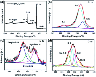 | ||
| Fig. 4 (a) XPS survey spectra and high resolution (b) C 1s, (c) N 1s, (d) O 1s and Sb 3d XPS spectra of Sb@Sb2O3/3DNC. | ||
Fig. 5 displays the N2 adsorption–desorption isotherms and the corresponding pore size distributions of Sb@Sb2O3/3DNC and NC. The BET surface area of Sb@Sb2O3/3DNC is 839.8 m2 g−1, far larger than that of the sample without adding SbCl3 in the synthetic process (NC: 114.4 m2 g−1), even though both of them present a large amount of micropores with a diameter of ∼2 nm. It demonstrates that the introduction of Sb3+ during the calcination process can greatly increase the specific surface area of materials, which may not only facilitate the penetration of the electrolyte into the electrode to improve the mass transport kinetics but also offers an extra area to accommodate volume changes during charge/discharge cycles.
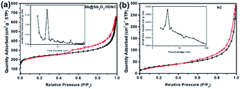 | ||
| Fig. 5 N2 adsorption–desorption isotherms and pore size distributions of (a) Sb@Sb2O3/3DNC and (b) NC. | ||
Electrochemical properties
To evaluate the Li storage performance of the developed samples, 2032-type coin cells were assembled using metallic Li foil as the counter electrode. Fig. S4† shows the cyclic voltammograms (CV) of Sb@Sb2O3/3DNC during the first cycles between 0 and 3 V at a scan rate of 0.1 mV s−1 at 25 °C. In the first cycle, there are two cathodic peaks located at 0.5 V and 1.2 V, likely corresponding to lithiation/the formation of solid electrolyte interphase (SEI) film and the irreversible conversion of Sb2O3 into Sb, respectively.27–30 In the following two cycles, the cathodic peak at 0.5 V shifts to 0.75 V, which is due to the lithiation of Sb to form LixSb.10,27 During the first anodic scan, the peaks at 1.2 V and 1.4 V can be ascribed to the dealloying of LixSb and the decomposition of LixO.10 After the first scan, the curves nearly overlap in the subsequent cycles, suggesting the high reversibility and stability of Sb@Sb2O3/3DNC. Fig. S5† displays the typical lithiation–delithiation voltage profiles at a current density of 100 mA g−1 of samples prepared with different ratios of precursors. Obviously, Sb–C–N–1–3–1 exhibits the best performance with the first charge and discharge capacities of 1810 mA h g−1 and 1109 mA h g−1, respectively, corresponding to an initial coulombic efficiency (CE) of 61.3%, which is far more than that of Sb–C–N–1–2–1 (58.7%) and Sb–C–N–1–4–1 (57.4%). As for the rate and cycle performance, Sb@Sb2O3/3DNC delivers a reversible capacity of 458 mA h g−1 at a high current density of 5 A g−1 (Fig. S5b†), and it shows no capacity decay after 500 cycles at a current density of 1 A g−1 (Fig. S5c†). It is worth noting that there is an overall capacity increase for all samples in the 300 cycles; such an activation process is mainly caused by the growth of an electrochemical active gel-like polymer layer, as well as the larger electrochemically active surface area of the porous architecture, which can enhance Li+ storage during cycles.31–33In order to provide further insights into the structure–performance correlation of the developed Sb@Sb2O3/3DNC anode, the rate and cycle performance of different control samples were evaluated (Fig. 6). Notably, Sb@Sb2O3/3DNC demonstrates the best electrochemical performance among all the samples, with a discharge capacity of 304.3 mA h g−1 at 5 A g−1 and 690.4 mA h g−1 after 400 cycles at 1 A g−1. In contrast, Sb@Sb2O3/C exhibits relatively low capacity (262 mA h g−1 at 5 A g−1) and poorer cycling stability (502 mA h g−1 after 400 cycles at 1 A g−1), indicating that the introduction of N can effectively enhance the reversible capacity and rate capability. On the other hand, the electrochemical performance of NC (145.8 mA h g−1 at 5 A g−1 and 502.3 mA h g−1 after 400 cycles at 1 A g−1) is much poorer than that of 3DNC with the removal of Sb@Sb2O3 (247 mA h g−1 at 5 A g−1 and 559 mA h g−1 after 400 cycles at 1 A g−1), which may be attributed to the possible larger specific surface area of 3DNC resulting from acid treatment. In addition, Sb@Sb2O3/3DNC and Sb/3DNC show excellent and comparable rate performance. From the first five active cycles at low current density in Fig. 6c, the sample without the Sb2O3 shell, owing to 1.0 M H2SO4 etching, experiences a relatively faster capacity loss and its reversible capacity remains at 550 mA h g−1 after 400 cycles, lower than that of Sb@Sb2O3/3DNC (650 mA h g−1). We speculate that it is not only due to the higher theoretical capacity of Sb2O3 than Sb, but also the synergistic effect between the two components that can accommodate the volume expansion as well as the Sb–O–C structure which facilitates the electron transfer between Sb@Sb2O3 and the carbon matrix. The thin coating of Sb2O3 is partly reduced to the Sb/Li2O nanocomposite during charge, and the amorphous phase Li2O can act as a buffer to relieve the volume change of Sb during cycling.27,34 This unique structure endows the materials with better electrochemical performance than most of the Sb-based LIB anodes reported so far.17,18,20–22 The Sb@Sb2O3/3DNC sample synthesized with the NaCl template and by freeze-drying presents the best electrochemical performance with the highest capacity and long-term stability (Fig. S6†), which can be attributed to the 3D porous network structure and high specific surface area of the sample.
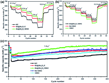 | ||
| Fig. 6 (a and b) Rate capability and (c) cycling performance of the NC, Sb@Sb2O3/C, Sb@Sb2O3/3DNC, Sb/3DNC, and 3DNC. | ||
Morphology and structure of post-cycle electrodes
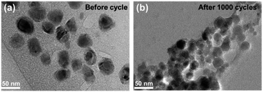
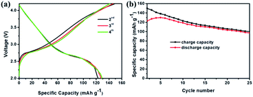
Fig. 7 compares the morphology and structure of Sb@Sb2O3/3DNC before (Fig. 7a) and after (Fig. 7b) 1000 cycles at 1 A g−1. TEM images demonstrate that even though some nanoparticles slightly aggregate and become smaller after such long cycles, the core@shell structure could still be preserved. The results indicate the strong structural stability between Sb@Sb2O3 and the 3D porous nanosheet matrix, which can maintain the structural reversibility in the long-term lithiation and delithiation process.To further explore the capability of the prepared Sb@Sb2O3/3DNC electrode in the practical application of LIBs, a full cell was assembled using Sb@Sb2O3/3DNC and NCM622 as the anode and cathode, respectively. The electrochemical performance of the full cell is tested and the results are displayed in Fig. 8. The obtained voltage profiles are within the voltage window of 2.0 to 4.5 V in the second to the fourth charge and discharge processes, and there is a voltage plateau at ca. 2.6 V in the discharge curve (Fig. 8a). Moreover, the cycling performance of the Sb@Sb2O3/3DNC‖NCM622 full cell is presented in Fig. 8b and the specific capacity is calculated based on the mass of the cathode. It should be noted that a discharge capacity of 100 mA h g−1 could be maintained after 25 cycles at a current density of 100 mA g−1, suggesting that Sb@Sb2O3/3DNC is a potentially promising anode material in realistic LIBs.
Conclusions
In summary, core@shell Sb@Sb2O3 particles anchored on 3D porous nitrogen-doped carbon nanosheets were developed and employed as an anode for LIBs for the first time. The resultant Sb@Sb2O3/3DNC hybrid is endowed with 3D porous N-doped carbon nanosheets and uniformly distributed Sb@Sb2O3 nanoparticles, which provide sufficient void space for relieving volume expansion and facilitating mass transport. Due to its unique structure, the Sb@Sb2O3/3DNC anode delivers a high charge capacity of 696.9 mA h g−1 after 500 cycles at a current density of 1 A g−1 and 458 mA h g−1 at 5 A g−1 in LIB tests, which outperforms most of the reported Sb-based anodes. The outstanding electrochemical performance indicates the potential of applying the developed anode material for LIBs. The facile synthetic approach taking the advantages of carefully designed metal nanostructures and electron-conductive buffer layers can be extended to the fabrication of other advanced electrode materials for next-generation energy storage.Conflicts of interest
There are no conflicts to declare.Acknowledgements
This work was financially supported by the National Materials Genome Project (2016YFB0700600) and National Natural Science Foundation of China (21972051). The authors thank the Analytical and Testing Center of Huazhong University of Science and Technology (HUST) for carrying out the XPS, SEM, TEM, TGA, and XRD measurements.References
- M. Armand and J. M. Tarascon, Nature, 2008, 451, 652–657 CrossRef CAS.
- L. Q. Mai, X. C. Tian, X. Xu, L. Chang and L. Xu, Chem. Rev., 2014, 114, 11828–11862 CrossRef CAS.
- J. Qin, C. N. He, N. Q. Zhao, Z. Y. Wang, C. S. Shi, E. Z. Liu and J. J. Li, ACS Nano, 2014, 8, 1728–1738 CrossRef CAS.
- S. W. Kim, D. H. Seo, X. H. Ma, G. Ceder and K. Kang, Adv. Energy Mater., 2012, 2, 710–721 CrossRef CAS.
- Y. G. Huang, Q. C. Pan, H. Q. Wang, C. Ji, X. M. Wu, Z. Q. He and Q. Y. Li, J. Mater. Chem. A, 2016, 4, 7185–7189 RSC.
- N. Chen, C. P. Han, R. Y. Shi, L. Xu, H. F. Li, Y. S. Liu, J. Q. Li and B. H. Li, Electrochim. Acta, 2018, 283, 36–44 CrossRef CAS.
- M. M. Lao, Y. Zhang, W. B. Luo, Q. Y. Yan, W. P. Sun and S. X. Dou, Adv. Mater., 2017, 29, 1700622 CrossRef.
- W. Luo, J. J. Gaumet and L. Q. Mai, Rare Met., 2017, 36, 321–338 CrossRef CAS.
- H. L. Lv, S. Qiu, G. X. Lu, Y. Fu, X. Y. Li, C. X. Hu and J. R. Liu, Electrochim. Acta, 2015, 151, 214–221 CrossRef CAS.
- A. Darwiche, C. Marino, M. T. Sougrati, B. Fraisse, L. Stievano and L. Monconduit, J. Am. Chem. Soc., 2013, 135, 10179 CrossRef CAS.
- L. Baggetto, P. Ganesh, C. N. Sun, R. A. Meisner, T. A. Zawodzinski and G. M. Veith, J. Mater. Chem. A, 2013, 1, 7985–7994 RSC.
- W. Luo, P. F. Zhang, X. P. Wang, Q. D. Li, Y. F. Dong, J. C. Hua, L. Zhou and L. Q. Mai, J. Power Sources, 2016, 304, 340–345 CrossRef CAS.
- W. Zhang, Y. T. Liu, C. J. Chen, Z. Li, Y. H. Huang and X. L. Hu, Small, 2015, 11, 3822–3829 CrossRef CAS.
- L. Wu, X. H. Hu, J. F. Qian, F. Pei, F. Y. Wu, R. J. Mao, X. P. Ai, H. X. Yang and Y. L. Cao, Energy Environ. Sci., 2014, 7, 323–328 RSC.
- Z. M. Liu, X. Y. Yu, X. W. D. Lou and U. Paik, Energy Environ. Sci., 2016, 9, 2314–2318 RSC.
- T. Ramireddy, M. M. Rahman, T. Xing, Y. Chen and A. M. Glushenkov, J. Mater. Chem. A, 2014, 2, 4282–4291 RSC.
- H. Li, K. Qian, X. Y. Qin, D. Q. Liu, R. Y. Shi, A. H. Ran, C. P. Han, Y. B. He, F. Y. Kang and B. H. Li, J. Power Sources, 2018, 385, 114–121 CrossRef CAS.
- J. Zhou, C. H. Zheng, H. Wang, J. Yang, P. F. Hu and L. Guo, Nanoscale, 2016, 8, 17131–17135 RSC.
- Y. Y. Fang, X. Xu, Y. C. Du, X. S. Zhu, X. S. Zhou and J. C. Bao, J. Mater. Chem. A, 2018, 6, 11244–11251 RSC.
- X. Zhang, F. Lai, Z. Chen, X. He, Q. Li and H. Wang, Electrochim. Acta, 2018, 283, 1689–1694 CrossRef CAS.
- X. Yang, J. J. Ma, H. J. Wang, Y. Q. Chai and R. Yuan, Mater. Chem. Phys., 2018, 213, 208–212 CrossRef CAS.
- L. Fan, J. J. Zhang, J. H. Cui, Y. C. Zhu, J. W. Liang, L. L. Wang and Y. T. Qian, J. Mater. Chem. A, 2015, 3, 3276–3280 RSC.
- W. Shen, C. Wang, Q. J. Xu, H. M. Liu and Y. G. Wang, Adv. Energy Mater., 2015, 5, 1400982 CrossRef.
- Z. Miao, X. Wang, M.-C. Tsai, Q. Jin, J. Liang, F. Ma, T. Wang, S. Zheng, B.-J. Hwang, Y. Huang, S. Guo and Q. Li, Adv. Energy Mater., 2018, 8, 1801226 CrossRef.
- F. Ma, Y. Wan, X. Wang, X. Wang, J. Liang, Z. Miao, T. Wang, C. Ma, G. Lu, J. Han, Y. Huang and Q. Li, ACS Nano, 2020, 14, 10115–10126 CrossRef CAS.
- F. Wan, J. Z. Guo, X. H. Zhang, J. P. Zhang, H. Z. Sun, Q. Y. Yan, D. X. Han, L. Niu and X. L. Wu, ACS Appl. Mater. Interfaces, 2016, 8, 7790–7799 CrossRef CAS.
- Y. N. Ko and Y. C. Kang, Chem. Commun., 2014, 50, 12322–12324 RSC.
- H. Zhang, X. T. Ma, C. Lin and B. K. Zhu, RSC Adv., 2014, 4, 33713–33719 RSC.
- Q. Sun, Q. Q. Ren, H. Li and Z. W. Fu, Electrochem. Commun., 2011, 13, 1462–1464 CrossRef CAS.
- O. A. Jaramillo-Quintero, M. Benítez-Cruz, J. L. García-Ocampo, A. Cano and M. E. Rincón, J. Alloys Compd., 2019, 807, 151647 CrossRef CAS.
- X. F. Li, Y. Zhong, M. Cai, M. P. Balogh, D. N. Wang, Y. Zhang, R. Y. Li and X. L. Sun, Electrochim. Acta, 2013, 89, 387–393 CrossRef CAS.
- Y. H. Xu, J. C. Guo and C. S. Wang, J. Mater. Chem., 2012, 22, 9562–9567 RSC.
- M. Y. Li, C. L. Liu, M. R. Shi and W. S. Dong, Electrochim. Acta, 2011, 56, 3023–3028 CrossRef CAS.
- K. Hong, D. Nam, S. Lim, D. Sohn, T. Kim and H. Kwon, ACS Appl. Mater. Interfaces, 2015, 7, 17264–17271 CrossRef CAS.
Footnotes |
| † Electronic supplementary information (ESI) available. See DOI: 10.1039/d0na00711k |
| ‡ These authors contributed equally to this work. |
| This journal is © The Royal Society of Chemistry 2020 |

