DOI:
10.1039/D4MH00301B
(Communication)
Mater. Horiz., 2024,
11, 4054-4063
Thermochemical production of ammonia via a two-step metal nitride cycle – materials screening and the strontium-based system†
Received
15th March 2024
, Accepted 20th June 2024
First published on 20th June 2024
Abstract
Ammonia synthesis via the catalytic Haber–Bosch process is characterized by its high pressures and low single-pass conversions, as well as by the energy-intensive production of the precursors H2 and N2 and their concomitant greenhouse gas emissions. Alternatively, thermochemical cycles based on metal nitrides stand as a promising pathway to green ammonia production because they can be conducted at moderate pressures without added catalysts and be further driven by concentrated solar energy as the source of high-temperature process heat. The ideal two-step cycle consists of the nitridation of a metal to form a metal nitride, followed by the hydrogenation of the metal nitride to synthetize NH3 and reform the metal. Here, we perform a combined theoretical and experimental screening of mono-metallic nitrides for several candidates, namely for Sr, Ca, Cr, Mn, Fe, Co, Ni, Cu, Zn, Mo, W, Li, and Al. For the theoretical screening, Ellingham diagrams and chemical equilibrium compositions are examined with thermodynamic data derived from density function theory computations. For the experimental screening, thermogravimetric runs and mass balances supported by on-line gas analyses are performed for both steps of the cycle at ambient pressure and over the temperature ranges 100–1000 °C for nitridation and 100–500 °C for hydrogenation. The strontium-based cycle is selected as a reference for detailed examination and shown to synthetize NH3 at 1 bar by effecting the nitridation at 407 °C (at peak rate) and the hydrogenation at 339 °C (at peak rate). The co-formation of metal hydrides (SrH2) and metal imides (Sr2HN) are shown to help close the material cycle.
New concepts
A promising pathway for the production of green ammonia via a thermochemical cycle is investigated. This 2-step cycle is based on the nitridation of a metal to form a metal nitride, followed by the hydrogenation of the metal nitride to synthetize NH3 and reform the metal. The nitridation and hydrogenation reactions can be performed at moderate pressures without added catalysts, and can be further driven by concentrated solar process heat. In this study, we apply a combined theoretical and experimental screening of mono-metallic systems to evaluate their feasibility for the cycle based on equilibrium thermodynamics and thermogravimetric analysis. The screening methodology is highlighted for the Sr-based system, for which the co-formation of metal hydrides and imides are shown to help close the material cycle.
|
Introduction
Increased global demand for ammonia (NH3) is driven by its application as a precursor for fertilizers in a growing world population1,2 as well as by its potential use as a hydrogen carrier3 and a zero-carbon fuel in the maritime sector.4 Synthetic ammonia is almost exclusively produced by the Haber–Bosch (H–B) process,5 consisting of the catalytic reaction between N2 and H2 at around 400 °C and 300 bar. Single-pass conversions typically do not exceed 25%. In 2021, worldwide production of ammonia was responsible for over 400 Mt of CO2-eq emissions, equivalent to 1.15% of the global anthropogenic CO2 emissions.6 The majority of these emissions stem from the energy-intensive production of N2 and H2, especially the latter as it is mainly produced by natural gas reforming driven by combustion process heat.5 The obvious alternative is to produce hydrogen by water electrolysis powered by solar/wind electricity,7 but it comes with certain techno-economic hurdles, such as the need for large-scale centralized electricity production and storage. Several alternative approaches to the H–B synthesis are being investigated based on electrochemical, photochemical, or plasma processes.8,9 The alternative explored in this work is the thermochemical production of NH3via a two-step cycle based on metal nitrides. This purely thermal cycle bypasses the need for electricity generation and, as will be shown in the analysis that follows, can be performed at more moderate pressures without added catalysts. More importantly, the cycle can be driven by high-temperature process heat supplied by concentrated solar energy. Notably, the technologies for realizing the solar concentrating and thermal storage infrastructure at large MW-scale are already established for commercial solar thermal power plants10 and can be readily applied to supply process heat at high temperatures and round-the-clock to a future industrial thermochemical plant.
The thermochemical cycle has two versions, requiring an input of either H2O (cycle I) or H2 (cycle II), and can be represented by the net ideal reactions:
Cycle I – with H2O input:
1st step: nitridation
| | | MxO3y + yN2 + 3yC → MxN2y + 3yCO | (1a) |
2nd step: hydrolysis
| | | MxN2y + 3yH2O → MxO3y + 2yNH3 | (1b) |
Cycle II – with H2 input:
1st step: nitridation
2nd step: hydrogenation
| | | MxN2y + 3yH2 → xM + 2yNH3 | (2b) |
where M denotes a generic metal. Depending on M, the nitridation step
(1a),
(2a) is thermodynamically favourable at high temperatures, while the hydrogenation/hydrolysis step
(1b),
(2b) is favourable at lower temperatures and higher pressures according to Le Chatelier's principle. Thus, analogous to the solar-driven redox cycles for splitting H
2O and CO
2, cycles I and II are performed by applying temperature/pressure swings between the steps. Cycle I, with an input of H
2O, avoids the need for H
2 but requires the input of a reducing agent,
e.g., C or CH
4, for the nitridation step
(1a) to serve as an oxygen scavenger of the metal oxide formed in the hydrolysis step
(1b). This reducing agent can be obtained from a biogenic source,
e.g., biochar, to ensure CO
2 neutrality. On the other hand, cycle II, with an input of H
2, avoids the need for a reducing agent in the nitridation step
(2a) at the expense of renewable H
2 in the hydrogenation step
(2b). This H
2 can, in turn, be obtained from H
2O
via a thermochemical redox cycle driven by concentrated solar energy.
11 Both cycles I and II require the input of N
2 for the nitridation step
(1a),
(2a), which, analogous to H
2, can be obtained from the air
via a thermochemical redox cycle driven by concentrated solar energy.
12 Thus, an integrated thermochemical plant will make use of concentrated solar energy to supply high-temperature process heat to the endothermic steps of the corresponding cycles for the separation of N
2 from air, for the production of H
2 from H
2O, and finally for the synthesis of NH
3 from H
2 and N
2. Such a scheme of 3 integrated thermochemical cycles for the production of NH
3 from air, water, and concentrated sunlight is shown in
Fig. 1. Solar-driven thermochemical processes inherently offer a thermodynamically efficient pathway because they use the entire solar spectrum and operate at high temperatures, leading to high energy efficiencies and reaction rates.
10
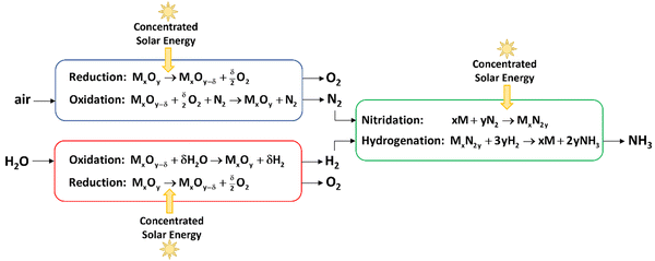 |
| | Fig. 1 Scheme of 3 integrated thermochemical cycles for the production of ammonia from air, water, and concentrated sunlight, consisting of: (1) a redox cycle for the separation of N2 from air (blue); (2) a redox cycle for the production of H2 from water (red), and (3) cycle II for the production of NH3 from H2 and N2 (green). Concentrated solar energy is used as the source of high-temperature process heat for the endothermic steps of the 3 cycles. | |
Cycle I was firstly proposed and experimentally demonstrated with AlN/Al2O3.13–15 The nitridation step ( ) proceeded at above 1300 °C, while the hydrolysis step (
 ) proceeded at below 375 °C; both steps were conducted at ambient pressure. Computational screening identified the candidates redox pairs Mo2N/MoO2, Mn5N2/MnO, BN/B2O3, VN/VO2, CeN/Ce7O12, FeN/Fe3O4, CrN/Cr2O3, WN2/WO3, MnN/MnO,16,17 while NH3 generation was experimentally confirmed during the hydrolysis of Li3N/LiO2, Ca3N2/CaO, Mg3N2/MgO, TiN/TiO2, ZrN/ZrO2.18,19 Cycle II was initially explored with Sr2N, Ca3N2, and Mn6N2.58, though the hydrogenation step did not recycle the pure metal but yielded the formation of metal hydrides and metal imides, i.e., SrH2 and Ca2HN.18 Five consecutive cycles with NH3 generation were shown for the LiH/Li2NH system20 and the Co3Mo3N/Co6Mo6N system,21 the latter performed at 700 °C and 1 bar for both steps. A recent high-throughput computational screening revealed 111 potential nitrides for this cycle.22 Low confidence in the approximated material properties used in the calculations highlighted the importance of complementary experimental validation.
In the present study, we develop a framework for a combined theoretical and experimental screening of metal nitrides suitable for application in cycle II. For the theoretical screening, we apply Ellingham diagrams and chemical equilibrium compositions. For the experimental screening, we perform thermogravimetric runs supported by on-line gas analyses. We focus on mono-metallic systems based on Sr, Ca, Cr, Mn, Fe, Co, Ni, Cu, Zn, Sr, Mo, W, Li, and Al. The Sr-based system is selected as a reference for detailed examination and for showing how accurate mass balances on both steps of the cycle can elucidate reaction mechanisms, identify species products, and validate the production of NH3.
Methods
Theoretical screening
Thermodynamic data for metal nitrides is rather scarce.23 To fill the gaps, thermodynamic data of relevant species for each of the metal nitride systems considered was obtained by Density Function Theory (0K-DFT) computations. The open-access database Materials Project (MP, database version: v2023.11.1)24 was used to obtain values of the following properties: elastic tensor to approximate the heat capacity by the Debye model,25,26 formation energy to approximate the formation enthalpy at standard conditions, and energy above the convex hull to gauge the stability against decomposition. Furthermore, the theoretical X-ray diffraction (XRD) patterns were used later in the experimental screening for phase identification. Entropy, enthalpy, and Gibbs free energy at non-standard conditions were calculated from the heat capacity. The formulation is given in the ESI.† This methodology enabled us to expand the theoretical screening by additional relevant species. For example, the Sr-system, with available data for Sr, SrH2, and Sr3N2 from the HSC Chemistry 5 database,27 was expanded to Sr2N, SrN, SrN2, and Sr2HN (see ESI†). Ellingham diagrams were created with a custom script that used HSC and MP data for the solids and the Shomate equation28 for the gases (H2, N2, NH3). Equilibrium composition diagrams were created with the HSC Chemistry 5 software after the DFT-derived data was incorporated into its database. It should be noted that both the 0K-DFT derived data and the approximation using the Debye model lead to uncertainties in the final thermodynamic data. Comparison of our computed data with the HSC data showed generally good agreement (see Fig. S1, ESI†). Note that the HSC data is also not free of uncertainties and thus only used here with limited warranty. To avoid the accidental ruling out of a candidate material, all tested materials were included in the experimental screening, independent of the findings from the theoretical screening.
Experimental screening
Thermogravimetric experimental runs were performed in a Setaram SETSYS 1750 CS Evolution thermogravimetric analyzer (TGA; resolution: 0.03 μg, measuring range ±200 mg). To remove the effects of buoyancy in the vertical suspension-type balance, the mass signals were corrected by subtracting a blank run. The gas flow rates were controlled by mass flow controllers (MFC, Bronkhorst EL-FLOW®) and set to 200 ml min−1 (precision: ±0.2% full scale and ±0.8% of the measurement) for all experiments. NH3 concentrations in ppm were measured on-line with an ABB Advance Optima AO2020 analyzer equipped with the UV photometer Limas21 (repeatability: ≤0.5% of span, detection limit (4σ): ≤1% of span). A Pfeiffer Vacuum OMNIStar GSD320 mass spectrometer (MS; detector type: Faraday, detection limit: <20 ppm) was used to qualitatively monitor the main gases N2, H2, NH3, Ar, and potential contaminants H2O and O2, and mono-atomic N (splitting of N2 due to ion source bombardment). Pressure, temperature, and gas flow rates after exiting the TGA and before entering the gas analysis devices were measured with a Mesa Labs DryCal Defender 530+ low flow meter (accuracy: 0.75% of reading). The flow meter measured the volumetric flow rate based on positive displacement. Since the composition of the gases exiting the TGA is a priori unknown, a mass-based flow meter cannot be used because it requires its measured signal to be adjusted by the gas correction factor for the specific gas composition. TGA and MS data were acquired by the instruments’ software; all other data were acquired with LabVIEW.
Strontium was supplied by Sigma-Aldrich as random flake pieces (99%, mm-range size) in a bottle filled with Ar under an oil film. The gases used during the experiments were Ar (PanGas, 99.996% purity), N2 (PanGas, 99.995% purity), 5% H2 in Ar (PanGas, 99.995% purity; lab safety regulations limited the concentration of H2 to a maximum of 5%). Prior to the thermogravimetric runs, the samples were loaded in alumina crucibles (Säntis Analytical AG) and had their initial mass determined with a Mettler Toledo XS105 DualRange scale (readability: d = 0.01 mg). Due to the sensitivity of the pure metals and metal nitrides with the oxygen and moisture in the air, samples were prepared inside a glove box filled with Ar, transported within sealed vials filled with Ar, and loaded into the TGA under an active Ar flow. However, exposure to air for a few seconds during loading/unloading could not be avoided. Each thermogravimetric run started with a short purge in which a vacuum is pulled to remove any unwanted gases in dead volumes, followed by an idle period where Ar is flowed at ambient temperature in order to establish a stable baseline of all measurement signals. Each run ended with the same idle period so that the overall mass change can be assessed free of any buoyancy effects that might have been left uncorrected by the blank run. To rid the sample of oil before the nitridation run, a drying run was performed at 300 °C in an Ar flow for 45 min. For the nitridation run, the sample was heated in N2 to 100 °C, kept there for 60 min for stabilization, and afterwards heated to 600 °C at a rate of 2 °C min−1 in N2. After the nitridation, the sample was removed from the TGA and ground into a powder between two sheets of weighing papers inside the glove box. Part of the powder was used for XRD and SEM analysis; the rest was weighed and transferred back to the TGA. Before the hydrogenation run, a drying run at 300 °C in N2 was performed to get rid of any potential volatiles adsorbed by the sample during its handling. For the hydrogenation run, the sample was heated in N2 to 100 °C, kept there for 60 min for stabilization, and afterwards heated to 500 °C at a rate of 2 °C min−1 in 5% H2/Ar. Compositions of solid reactants and products were determined by X-ray powder diffraction (XRD) on a STOE STADI P diffractometer equipped with a DECTRIS MYTHEN 1K detector in transmission mode using a Ge monochromator for Cu Kα1 (1.5406 Å) radiation and a Bruker AXS D8 Advance diffractometer operated at 40 kV and 30 mA (Cu Kα). To ensure air tightness, samples were enclosed between two layers of Kapton tape. XRD reference patterns were aggregated from the Inorganic Crystal Structure Database (ICSD)29 and the Materials Project database. Morphologies of selected samples were examined by scanning electron microscopy (SEM, Hitachi TM1000 Tabletop).
Results & discussion
Theoretical screening
The Ellingham diagrams feature species that have an exergonic region, i.e., reactions proceed spontaneously in the temperature range displayed and allow a nitridation/hydrogenation cycle to be closed. Fig. 2 shows the Ellingham diagrams of the reactions of cycle II for the systems based on Ca, Cr, Mn, Fe, Co, Ni, Cu, Zn, Sr, Mo, W, Li, and Al. Plotted is the standard Gibbs free energy change  as a function of temperature: (a)
  per mol N2 for the nitridation reactions according to eqn (2a), and; (b)
  per mol H2 for the hydrogenation reactions according to eqn (2b). All the reactions considered are listed in the ESI.†
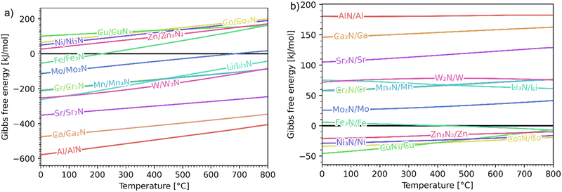 |
| | Fig. 2 Ellingham diagrams of the reactions of cycle II for the systems based on Ca, Cr, Mn, Fe, Co, Ni, Cu, Zn, Sr, Mo, W, Li, and Al: (a) standard  per mol N2 as a function of temperature in the range of 0–800 °C for the nitridation reactions according to eqn (2a), and; (b) standard per mol N2 as a function of temperature in the range of 0–800 °C for the nitridation reactions according to eqn (2a), and; (b) standard  per mol H2 as a function of temperature in the range of 0–800 °C for the hydrogenation reactions according to eqn (2b). Indicated are the corresponding metal/metal nitride systems. per mol H2 as a function of temperature in the range of 0–800 °C for the hydrogenation reactions according to eqn (2b). Indicated are the corresponding metal/metal nitride systems. | |
The formation of the metal nitrides (eqn (2a)) proceeds spontaneously at 1 bar and at below 800 °C for Al/AlN, Ca/Ca2N, Sr/Sr2N, W/W2N, Mn/Mn4N, Cr/Cr2N, and Li/Li3N; at below 687 °C for Mo/Mo2N; and at below 219 °C for Fe/Fe3N. For the systems Ni/Ni3N, Zn/Zn3N2, Co/Co3N, and Cu/CuN3, reaction (2a) does not proceed spontaneously at 1 bar. The hydrogenation with formation of NH3 (eqn (2b)) proceeds spontaneously at below 800 °C for CuN3/Cu, Co3N/Co, Ni3N/Ni, and Zn3N2/Zn; and at above 416 °C for Fe3N/Fe. For the remaining metal nitrides, reaction (2b) does not proceed spontaneously at 1 bar. At higher pressures, the formation of metal nitrides by nitridation and of NH3 by hydrogenation become more thermodynamically favourable. For the Fe-based system, the ideal cycle analysis returns only the Fe/Fe3N pair as a potential candidate to close a nitridation/hydrogenation cycle. However, nitridation of Fe did not lead to any detectable reaction (see Fig. S141 and S142, ESI†). Note that the Fe-nitridation step becomes thermodynamically favourable at below 219 °C, but at such relatively low temperatures the reaction is kinetically controlled and presumably inhibited from attaining reasonable rates using the TGA experimental setup. Furthermore, very specific conditions, e.g. polished surfaces and nitridation by NH3, had to be applied in the past for the synthesis of Fe3N.30 Further investigation is thus warranted, potentially also at higher pressures, which thermodynamically favour the nitridation step according to Le Châtelier's principle (see reaction (2a)).
Previous studies report the formation of metal hydrides or metal imides,18,20 and their presence was also observed in some preliminary experimental TGA runs (see ESI†). The formation of such species can change the energetics of the NH3 production in these cycles and will therefore be further examined in this paper, in particular for the reference Sr-based system. The complete list of species and reactions considered, along with their thermodynamic data and corresponding Ellingham diagrams, are given in the ESI.† The detailed theoretical analysis is summarized here for the Sr-based system.
Sr-based system.
The nitridation step encompasses the following reactions (listed are the corresponding values of their standard enthalpy change at 25 °C):| |  | (3) |
| |  | (4) |
| |  | (5) |
| |  | (6) |
Fig. 3 shows the Ellingham diagram of these reactions: the Gibbs free energy change per mol N2 is plotted as a function of temperature in the range of 0–800 °C for: (a) standard  ; and (b) ΔGrxn at 50 bar (below the pressure of the H–B process) assuming 20% reaction extent (comparable to the single-pass conversion of the H–B process). The shaded areas indicate the regions favouring the formation of NH3. With the exception of reaction (3) with pure Sr, all reactions are endothermic. Among the SrH2 nitridations, reaction (4) yielding H2 appears to be the most favourable one at above 245 °C. However, since the ΔGrxn of reaction (5) lies close to the abscissa and exhibits a very shallow slope, small errors in the derived thermodynamic data can have a significant effect on the equilibrium temperature for the onset of the reaction. With increasing pressure, reactions (4) and (6) become less favourable as a consequence of Le Chatelier's principle. On the other hand, reaction (5) is unaffected by pressure change and, interestingly, yields NH3 in the nitridation step.
 |
| | Fig. 3 Ellingham diagram of the nitridation step for reactions (3)–(6). Variation of the Gibbs free energy change per mol N2 as a function of temperature for (a) standard  ; and (b) ΔGrxn at 50 bar assuming 20% reaction extent. ; and (b) ΔGrxn at 50 bar assuming 20% reaction extent. | |
The hydrogenation step involves mainly the following exothermic reactions (listed are the corresponding values of their standard enthalpy change at 25 °C):
| |  | (7) |
| |  | (8) |
| |  | (9) |
| |  | (10) |
| |  | (11) |
Fig. 4 shows the Ellingham diagram of these reactions: the standard Gibbs free energy change per mol H
2 is plotted as a function of temperature in the range of 0–800 °C for: (a) standard

; and (b) Δ
Grxn at 50 bar assuming 20% reaction extent (comparable to that of the H–B process). The shaded areas indicate the regions favouring the formation of NH
3. All reactions are exothermic.
Reactions (10) and (11) involving Sr
2HN proceed spontaneously below 218 and 245 °C, respectively. At these relatively low temperatures, slow kinetics might affect their rates. Higher pressures shift the equilibrium to the right, which would allow the reactions to proceed at higher temperatures, with a better outlook for fast kinetics.
Reaction (7) is highly exergonic and hinders the formation of NH
3 by
reactions (8) and (9). Note that none of the hydrogenation reactions reform pure Sr. Nevertheless, the material cycle can be closed through the formation of SrH
2 during hydrogenation, which in turn reacts with N
2 to form Sr
2N and Sr
2HN during nitridation.
 |
| | Fig. 4 Ellingham diagram of the hydrogenation step for the reactions (7)–(11). Variation of the Gibbs free energy change per mol H2 as a function of temperature for: (a) standard  ; and (b) ΔGrxn at 50 bar assuming 20% reaction extent. ; and (b) ΔGrxn at 50 bar assuming 20% reaction extent. | |
Fig. 5 shows the chemical equilibrium composition of the Sr–H–N system as a function of temperature at 1 bar. The initial conditions were chosen to be 1 mol of Sr2N + 10 mol H2 (excess H2 not visible in the plot). For clarity, species with less than 10−3 mol have been omitted from the plot (Sr, SrN, SrN2, Sr3N2). Since the Ellingham diagram of Fig. 4 includes the reactions (10) and (11), the equilibrium composition plot with initial conditions 1 mol Sr2HN + 10 mol H2 was also constructed to confirm that it ends in the same equilibrium state. Noticeable NH3 evolution is possible at equilibrium up to around 400 °C, but slow kinetics are expected at below 200 °C. Thus, in the temperature range of interest 200–400 °C, the equilibrium system at 1 bar contains NH3 and N2 in the gas phase and SrH2 and Sr2HN in the solid phase. Both reactions (10) and (11) yield SrH2 and exhibit comparable Gibbs free energy curves (see Fig. 2(a)), but the former produces NH3 while the latter produces N2. This impedes the ability to draw conclusions about the gas phase composition based on the measured mass change of the solid phase, as it will be discussed in the Experimental Screening section. As expected from Le Chatelier's principle, higher pressures favour NH3 formation, as indicated by the curves at 10 and 50 bars (see Fig. 5). At 300 °C and 50 bars, the equilibrium composition consists predominantly of NH3 in the gas phase and SrH2 in the solid phase.
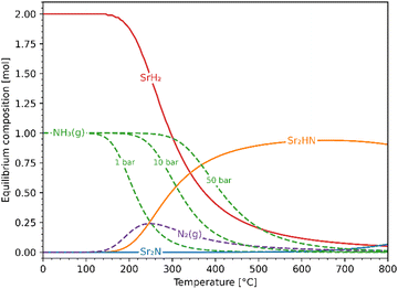 |
| | Fig. 5 Equilibrium composition of the Sr–H–N system as a function of temperature at 1 bar with initial conditions Sr2N + 10H2. Also shown are the NH3 curves at 10 and 50 bar. Solid lines: solid phases; dashed lines: gaseous phases. | |
Experimental screening
Thermogravimetric nitridation and hydrogenation experimental runs were performed for the following metal precursors: Sr, Ca, Cr, Mn, Fe, Co, Ni, Cu, Zn, Mo, W, Li, and Al. Successful nitridation was achieved for Sr (Sr2N), Ca (unidentifiable nitride), Cr (Cr2N, CrN), Mn (Mn5N2, Mn4N), and Al (AlN). Of those, only the Sr-based and Al-based nitrides produced NH3 at clearly detectable levels during hydrogenation. Representative experimental measurements are given in the ESI.† The details of the experimental analysis are summarized here for the reference Sr-based system.
Nitridation.
A 45.31 mg sample of pure Sr coated in oil was first dried at 300 °C in an Ar flow. After drying, the sample directly underwent nitridation by heating it from 100 to 600 °C with a heating ramp of 2 °C min−1 under a 200 ml min−1 flow of 100% N2. Fig. 6 shows the variations of mass (recorded by the TGA) and ion current (recorded by the mass spectrometer) as a function of time and temperature during this run. The mass increase of 7.82% is close to the theoretical 7.99% for full conversion of Sr to Sr2N according to reaction (3) (marked with dashed lines). The onset of the reaction proceeded at 200 °C, and its rate increased and peaked at around 400 °C. The H2 mass spectrometer signal deviated slightly in the range 300–400 °C, presumably due to trace amounts of evaporated oil.
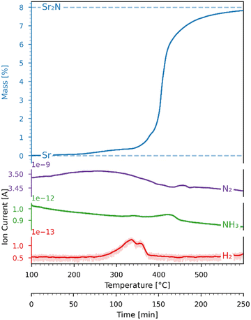 |
| | Fig. 6 Variations of mass (recorded by the TGA) and ion current (recorded by the mass spectrometer) as a function of time and temperature for the Sr-nitridation under 100% N2. Blue dashed lines: theoretical mass changes for no conversion (0%) and full conversion to Sr2N (7.99%) according to reaction (3). The ion current signals correspond to N2 (purple), NH3 (green), and H2 (red). | |
Hydrogenation.
The Sr2N sample used for the hydrogenation was first nitridated according to Fig. 6, ground into a powder form, and loaded back into the TGA. The sample was hydrogenated by heating it from 100 to 500 °C with a ramp of 2 °C min−1 under a 200 ml min−1 flow of 5% H2 in Ar. Fig. 7 shows the variations of mass (recorded by the TGA), NH3 concentration (recorded by the ammonia analyzer), and ion current (recorded by the mass spectrometer) as a function of time and temperature during this run. The NH3 signal is shown before (light green) and after (dark green) being smoothed by a Savitzky–Golay filter. Indicated with blue dashed lines are the theoretical mass changes for no conversion (0%) and full conversion to Sr2HN (0.53%) and to SrH2 (−5.27%) according to reactions (7)–(9). Indicated with a blue dash-dotted line is the equilibrium between SrH2 and Sr2HN, as predicted in Fig. 5, calculated by  , where nSr2HN and nSrH2 are the mole amounts in equilibrium and ntot being their sum. Equilibrium composition predicts a mass change of −0.54%. The onset of the reaction proceeded at 207 °C, and its rate peaked at around 339 °C, coinciding with the peak of NH3 of 55 ppm. The mass of Sr2N was 22.08 mg at the start of the ramp and 21.84 mg at the end, which corresponds to a total mass change of −1.06%. Assuming full conversion of Sr2N to Sr2HN and SrH2, this corresponds to a Sr2HN mass of 15.02 mg (68.79%) and a SrH2 mass of 6.82 mg (31.22%), resulting in 0.53 mg of nitrogen atoms released. The mass of NH3 produced was 0.27 mg, which is equivalent to a nitrogen mass of 0.22 mg. Therefore, around 40% of the released N-atoms were used to form NH3. The full conversion of Sr2N to SrH2 would have amounted to a theoretical yield of 1.63 mg of released nitrogen atoms, hence the yield of the measured NH3 production is 13.37%. This is still below the typical yield of the H–B process, but a promising starting point considering the experimental run was performed at ambient pressure. Note, that the initial elevated signal of NH3 and N2 was purely an artefact of the gas flow switch from 100% Ar to 5% H2 in Ar, as verified in blank runs.
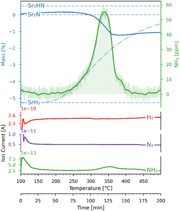 |
| | Fig. 7 Variations of mass (recorded by the TGA) and ion current (recorded by the mass spectrometer) as a function of time and temperature for the Sr2N-hydrogenation under 5% H2 in Ar. Blue dashed lines: theoretical mass changes for no conversion (0%) and full conversion to Sr2HN (0.53%) and SrH2 (−5.27%) according to reactions (7)–(9). Blue dash-dotted line: equilibrium between SrH2 and Sr2HN. The ion current signals correspond to N2 (purple), NH3 (green), H2 (red). | |
Fig. 8 shows the mass balance evaluation performed on the hydrogenation run of Fig. 7. The top plot shows the variation of the masses of the TGA sample and nitrogen released in the form of NH3 as a function of time and temperature; the second plot shows the difference between them. The bottom plots show the ion currents (recorded by the mass spectrometer) before (light color) and after (dark color) being smoothed by a Savitzky–Golay filter. The temperature range has been narrowed to focus on the section where the reactions occur. The mass change in mg measured by the TGA mTGA is displayed by the orange line, which is the sum of nitrogen atoms (MN = 14.0067 g mol−1) released and hydrogen (MH = 1.00794 g mol−1) atoms gained by the sample. The concentration measurement in ppm of the NH3 analyzer was converted to a mass in mg and then converted to an equivalent mass of nitrogen atoms mN,NH3 = mNH3·MN/MNH3 which is plotted as a green line. This plot indicates that not all of the released nitrogen atoms reacted to NH3 but recombined to N2 instead. While the mass spectrometer registered a drop in H2 concentration as the rate of reaction increased, it was not sensitive enough to register a change in N2 concentration. The difference in mg between mTGA and mN,NH3 (displayed in the second plot as a green line) reveals the presence of three distinct reaction zones of nearly linear slopes. The linear regressions are indicated by the red dashed lines. In the first zone, in the range 207–311 °C, all the released nitrogen is converted to NH3. In the second zone, in the range 311–362 °C, the sample releases more nitrogen atoms than are converted to NH3. The selectivity towards NH3 in the experiment is higher than that expected from the equilibrium analysis (see Fig. 5). In the third zone, in the range 362–405 °C, the negative slope in the lower plot suggests that the uptake of hydrogen atoms exceeds the release of nitrogen atoms.
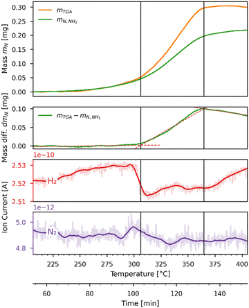 |
| | Fig. 8 Comparison of nitrogen mass equivalents as measured by the TGA (orange) and the NH3 analyzer (green) as a function of time and temperature during the Sr2N-hydrogenation run of Fig. 7. The top plot shows the measured and predicted nitrogen masses in mg. The second plot shows the difference between the TGA and NH3 analyzer nitrogen mass in mg. The bottom plots show the ion current (recorded by the mass spectrometer) for H2 (red) and N2 (purple). | |
Solid characterization.
The high reactivity of the samples with ambient humid air made it difficult to perform the XRD measurements free of contamination. Fig. 9 shows the XRD patterns of the solid product after Sr-nitridation (see Fig. 6). The Sr2N reference pattern (ICSD #411612) can be clearly identified. Since the TGA indicated nearly full conversion of Sr to Sr2N, it can be assumed that contamination occurred when handling the sample, as evidenced by the presence of SrHN (ICSD #158968), SrO (ICSD #163625), and Sr(OH)2 (ICSD #15167). Fig. 10 shows the XRD patterns of the solid product after Sr2N-hydrogenation (see Fig. 7). Also here, oxidation with air occurred during sample handling, as evidenced by the presence of SrO2 (MP mpid-1179089) and Sr(OH)2 (ICSD #15167). The reference pattern for Sr2HN (ICSD #138636) is slightly shifted but can still be identified. The presence of SrH2 (ICSD #33160) is inconclusive as it shares its highest intensity peaks with the contaminants. Its formation is strongly implied by the TGA results since the only way for Sr2N to undergo weight loss is through the formation of either Sr or SrH2, but the latter is thermodynamically more favourable as indicated by the Gibbs free energy change at 339 °C for reactions (8) and (Sr-R020, see Table S24 in ESI†):  ;
;  . The absence of a distinct peak at 2Θ = 12.8° for Sr2N (see Fig. 9) supports the assumption of complete conversion, consistent with the results of the TGA run (see Fig. 7).
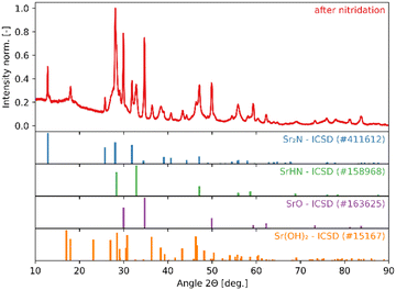 |
| | Fig. 9 XRD patterns of the solid product of Sr-nitridation (see Fig. 6). Peak intensities have been normalized. | |
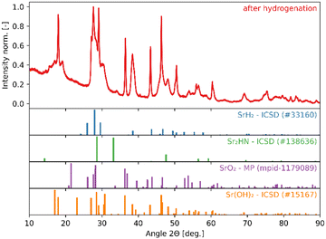 |
| | Fig. 10 XRD patterns of the solid product of Sr2N-hydrogenation (see Fig. 7). Peak intensities have been normalized. | |
Fig. 11 shows the SEM images of the solid products of Sr-nitridation (left) and Sr2N-hydrogenation (right). The sample after nitridation exhibits a uniform and porous morphology beneficial for diffusion, but the fine structures are prone to sinter which slows the kinetic rates. The sample after hydrogenation features similar porous surface seen in the reactant, next to a smoother and compact surface which might become a diffusion barrier.
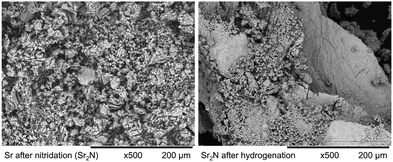 |
| | Fig. 11 SEM images of the solid products of Sr-nitridation (left) and Sr2N-hydrogenation (right) (500× magnification). | |
Conclusions
The thermochemical production of ammonia via a two-step nitridation-hydrogenation cycle (cycle II) has been investigated for several metal nitride systems. The combined theoretical and experimental analysis served as a rapid screening of candidate materials for the cycle. The challenges were: (1) obtaining thermodynamic data of relevant species needed for creating the Ellingham diagrams and for computing the chemical equilibrium compositions; (2) quantifying on-line the evolution of NH3 during hydrogenation and closing mass balances for both steps of the cycle. Only mono-metallic nitrides were examined in this study, but the screening methodology can also be applied to bi-metallic nitrides. In particular, the Sr-based system was selected as a reference for the detailed theoretical and experimental screening. For this system, the Ellingham diagrams and chemical equilibrium compositions indicated that NH3 formation is thermodynamically favourable in the temperature range of 200–400 °C even at 1 bar. Increasing the operating pressure to 50 bar should increase the NH3 yield and approach 100% at up to around 300 °C. The analysis further unveiled the presence of several competing reactions involving SrH2 and Sr2HN. TGA runs for Sr-nitridation yielded nearly full conversion to Sr2N, while runs for Sr2N-hydrogenation yielded a mixture of Sr2HN (68.79%) and SrH2 (31.22%). Both steps of the cycle were performed at ambient pressure. Mass balance calculations based on the experimental weight change and gas analysis indicated that a sample of 22.08 mg Sr2N produced a total of 0.27 mg NH3, corresponding to an ammonia yield of 13.37%. In general, the experimental results are consistent with the equilibrium predictions. Interestingly, the selectivity towards NH3 in the hydrogenation run is higher than that expected from the equilibrium analysis at 1 bar, which further predicts that NH3 formation should increase with pressure. Stability over multiple cycles has still to be proven, preferably at below 300 °C and up to 50 bar during hydrogenation to approach complete conversion to NH3 as predicted by thermodynamics. TGA experimental runs were also performed for the systems based on Ca, Cr, Mn, Fe, Co, Ni, Cu, Zn, Mo, W, Li, and Al, but only the Al-based cycle produced NH3 during hydrogenation of AlN. Further screening of mono/bi-metallic nitrides is required to determine their suitability for generating ammonia through the thermochemical cycle at moderate pressures and without added catalysis.
Author contributions
D. N. and A. S.: conceptualization, investigation, writing – original draft, review & editing. D. N.: methodology. T. E. A. S.: investigation. M. E. G. and B. B.: investigation, writing – review & editing. A. S.: supervision.
Data availability
The data supporting this article have been included as part of the ESI.†
Conflicts of interest
There are no conflicts to declare.
Acknowledgements
We thank Prof. Greta R. Patzke, Dr Madhusudhan Naik Jarpla, and Dr Carlos Tirana from the Department of Chemistry at University of Zurich for the XRD analysis. We further thank Thomas Frei and Francesco Sperelli for their support with the TGA and SEM measurements and Timmy Frischknecht for his support with the initial theoretical screening.
References
-
IEA, Ammonia Technology Roadmap, OECD, Paris, 2021.
- J. W. Erisman, M. A. Sutton, J. Galloway, Z. Klimont and W. Winiwarter, Nat. Geosci., 2008, 1, 636–639 Search PubMed.
- F. B. Juangsa, A. R. Irhamna and M. Aziz, Int. J. Hydrogen Energy, 2021, 1–23 Search PubMed.
- A. Valera-Medina, F. Amer-Hatem, A. K. Azad, I. C. Dedoussi, M. De Joannon, R. X. Fernandes, P. Glarborg, H. Hashemi, X. He, S. Mashruk, J. McGowan, C. Mounaim-Rouselle, A. Ortiz-Prado, A. Ortiz-Valera, I. Rossetti, B. Shu, M. Yehia, H. Xiao and M. Costa, Energy Fuels, 2021, 35, 6964–7029 CrossRef CAS.
- C. Smith, A. K. Hill and L. Torrente-Murciano, Energy Environ. Sci., 2020, 13, 331–344 RSC.
-
IEA, Chemicals, Paris, 2022.
- S. A. Grigoriev, V. N. Fateev, D. G. Bessarabov and P. Millet, Int. J. Hydrogen Energy, 2020, 45, 26036–26058 Search PubMed.
- L. Wang, M. Xia, H. Wang, K. Huang, C. Qian, C. T. Maravelias and G. A. Ozin, Joule, 2018, 2, 1055–1074 CrossRef CAS.
- Q. Wang, J. Guo and P. Chen, J. Energy Chem., 2019, 36, 25–36 Search PubMed.
- M. Romero and A. Steinfeld, Energy Environ. Sci., 2012, 5, 9234–9245 RSC.
- K. J. Warren and A. W. Weimer, Sol. Compass, 2022, 1, 100010 CrossRef.
- B. Bulfin, L. Buttsworth, A. Lidor and A. Steinfeld, Chem. Eng. J., 2021, 421, 127734 Search PubMed.
- M. E. Gálvez, M. Halmann and A. Steinfeld, Ind. Eng. Chem. Res., 2007, 46, 2042–2046 CrossRef.
- M. E. Gálvez, A. Frei, M. Halmann and A. Steinfeld, Ind. Eng. Chem. Res., 2007, 46, 2047–2053 CrossRef.
- M. E. Gálvez, I. Hischier, A. Frei and A. Steinfeld, Ind. Eng. Chem. Res., 2008, 47, 2231–2237 Search PubMed.
- R. Michalsky, P. H. Pfromm and A. Steinfeld, Interface Focus, 2015, 5, 1–10 CrossRef PubMed.
- C. J. Bartel, J. R. Rumptz, A. W. Weimer, A. M. Holder and C. B. Musgrave, ACS Appl. Mater. Interfaces, 2019, 11, 24850–24858 CrossRef CAS PubMed.
- R. Michalsky, A. M. Avram, B. A. Peterson, P. H. Pfromm and A. A. Peterson, Chem. Sci., 2015, 6, 3965–3974 RSC.
- S. Abanades, B. Rebiere, M. Drobek and A. Julbe, Chem. Eng. Sci., 2024, 283, 119406 CrossRef CAS.
- H. Yan, W. Gao, Q. Wang, Y. Guan, S. Feng, H. Wu, Q. Guo, H. Cao, J. Guo and P. Chen, J. Phys. Chem. C, 2021, 125, 6716–6722 CrossRef CAS.
- N. P. Nguyen, S. Kaur, H. E. Bush, J. E. Miller, A. Ambrosini and P. G. Loutzenhiser, Adv. Energy Mater., 2024, 14, 2302740 CrossRef CAS.
- R. J. Lee Pereira, I. S. Metcalfe and W. Hu, Appl. Energy
Combust. Sci., 2023, 16, 100226 Search PubMed.
- W. Sun, C. J. Bartel, E. Arca, S. R. Bauers, B. Matthews, B. Orvañanos, B. R. Chen, M. F. Toney, L. T. Schelhas, W. Tumas, J. Tate, A. Zakutayev, S. Lany, A. M. Holder and G. Ceder, Nat. Mater., 2019, 18, 732–739 Search PubMed.
- A. Jain, S. P. Ong, G. Hautier, W. Chen, W. D. Richards, S. Dacek, S. Cholia, D. Gunter, D. Skinner, G. Ceder and K. A. Persson, APL Mater., 2013, 1, 011002 Search PubMed.
- J. Vieten, B. Bulfin, P. Huck, M. Horton, D. Guban, L. Zhu, Y. Lu, K. A. Persson, M. Roeb and C. Sattler, Energy Environ. Sci., 2019, 12, 1369–1384 RSC.
-
N. W. Ashcroft and N. D. Mermin, Solid State Physics [Festkörperphysik], Oldenbourg Wissenschaftsverlag, München, 2001 Search PubMed.
-
A. Roine, Outokumpu HSC Chemistry® for Windows (Version 5.0), Outokumpu Research Oy, Pori, Finland, 2002 Search PubMed.
-
M. W. Chase, NIST-JANAF Thermochemical Tables 2 Volume-Set, American Institute of Physics, 4th edn, 1998 Search PubMed.
- D. Zagorac, H. Muller, S. Ruehl, J. Zagorac and S. Rehme, J. Appl. Crystallogr., 2019, 52, 918–925 Search PubMed.
- Y. Inokuti, N. Nishida and N. Ohashi, Metallurgical, 1975, 6, 773–784 Search PubMed.
|
| This journal is © The Royal Society of Chemistry 2024 |
Click here to see how this site uses Cookies. View our privacy policy here.  Open Access Article
 a,
Tiago
Elias Abi-Ramia Silva
 a,
María Elena
Gálvez
 b,
Brendan
Bulfin
 c and
Aldo
Steinfeld
 *a
*a
 ) proceeded at above 1300 °C, while the hydrolysis step (
 ) proceeded at below 375 °C; both steps were conducted at ambient pressure. Computational screening identified the candidates redox pairs Mo2N/MoO2, Mn5N2/MnO, BN/B2O3, VN/VO2, CeN/Ce7O12, FeN/Fe3O4, CrN/Cr2O3, WN2/WO3, MnN/MnO,16,17 while NH3 generation was experimentally confirmed during the hydrolysis of Li3N/LiO2, Ca3N2/CaO, Mg3N2/MgO, TiN/TiO2, ZrN/ZrO2.18,19 Cycle II was initially explored with Sr2N, Ca3N2, and Mn6N2.58, though the hydrogenation step did not recycle the pure metal but yielded the formation of metal hydrides and metal imides, i.e., SrH2 and Ca2HN.18 Five consecutive cycles with NH3 generation were shown for the LiH/Li2NH system20 and the Co3Mo3N/Co6Mo6N system,21 the latter performed at 700 °C and 1 bar for both steps. A recent high-throughput computational screening revealed 111 potential nitrides for this cycle.22 Low confidence in the approximated material properties used in the calculations highlighted the importance of complementary experimental validation.
 as a function of temperature: (a)
  per mol N2 for the nitridation reactions according to eqn (2a), and; (b)
  per mol H2 for the hydrogenation reactions according to eqn (2b). All the reactions considered are listed in the ESI.†

 per mol N2 as a function of temperature in the range of 0–800 °C for the nitridation reactions according to eqn (2a), and; (b) standard
  per mol H2 as a function of temperature in the range of 0–800 °C for the hydrogenation reactions according to eqn (2b). Indicated are the corresponding metal/metal nitride systems.


 ; and (b) ΔGrxn at 50 bar (below the pressure of the H–B process) assuming 20% reaction extent (comparable to the single-pass conversion of the H–B process). The shaded areas indicate the regions favouring the formation of NH3. With the exception of reaction (3) with pure Sr, all reactions are endothermic. Among the SrH2 nitridations, reaction (4) yielding H2 appears to be the most favourable one at above 245 °C. However, since the ΔGrxn of reaction (5) lies close to the abscissa and exhibits a very shallow slope, small errors in the derived thermodynamic data can have a significant effect on the equilibrium temperature for the onset of the reaction. With increasing pressure, reactions (4) and (6) become less favourable as a consequence of Le Chatelier's principle. On the other hand, reaction (5) is unaffected by pressure change and, interestingly, yields NH3 in the nitridation step.

 ; and (b) ΔGrxn at 50 bar assuming 20% reaction extent.


 ; and (b) ΔGrxn at 50 bar assuming 20% reaction extent (comparable to that of the H–B process). The shaded areas indicate the regions favouring the formation of NH3. All reactions are exothermic. Reactions (10) and (11) involving Sr2HN proceed spontaneously below 218 and 245 °C, respectively. At these relatively low temperatures, slow kinetics might affect their rates. Higher pressures shift the equilibrium to the right, which would allow the reactions to proceed at higher temperatures, with a better outlook for fast kinetics. Reaction (7) is highly exergonic and hinders the formation of NH3 by reactions (8) and (9). Note that none of the hydrogenation reactions reform pure Sr. Nevertheless, the material cycle can be closed through the formation of SrH2 during hydrogenation, which in turn reacts with N2 to form Sr2N and Sr2HN during nitridation.

 ; and (b) ΔGrxn at 50 bar assuming 20% reaction extent.
 , where nSr2HN and nSrH2 are the mole amounts in equilibrium and ntot being their sum. Equilibrium composition predicts a mass change of −0.54%. The onset of the reaction proceeded at 207 °C, and its rate peaked at around 339 °C, coinciding with the peak of NH3 of 55 ppm. The mass of Sr2N was 22.08 mg at the start of the ramp and 21.84 mg at the end, which corresponds to a total mass change of −1.06%. Assuming full conversion of Sr2N to Sr2HN and SrH2, this corresponds to a Sr2HN mass of 15.02 mg (68.79%) and a SrH2 mass of 6.82 mg (31.22%), resulting in 0.53 mg of nitrogen atoms released. The mass of NH3 produced was 0.27 mg, which is equivalent to a nitrogen mass of 0.22 mg. Therefore, around 40% of the released N-atoms were used to form NH3. The full conversion of Sr2N to SrH2 would have amounted to a theoretical yield of 1.63 mg of released nitrogen atoms, hence the yield of the measured NH3 production is 13.37%. This is still below the typical yield of the H–B process, but a promising starting point considering the experimental run was performed at ambient pressure. Note, that the initial elevated signal of NH3 and N2 was purely an artefact of the gas flow switch from 100% Ar to 5% H2 in Ar, as verified in blank runs.


 ;
;  . The absence of a distinct peak at 2Θ = 12.8° for Sr2N (see Fig. 9) supports the assumption of complete conversion, consistent with the results of the TGA run (see Fig. 7).


