 Open Access Article
A 3D printed hydrostatic skeleton for an earthworm-inspired soft burrowing robot
Ryuma
Niiyama
 *a,
Kazuma
Matsushita
*b,
Masahiro
Ikeda
a,
Keung
Or
a and
Yasuo
Kuniyoshi
b
aMeiji University – Ikuta Campus, 1-1-1 Higashimita, Tamaku, Kawasaki, Kanagawa 214-8571, Japan. E-mail: niiyama@meiji.ac.jp; Tel: +81 044 934 7266
bThe University of Tokyo, 7-3-1 Hongo, Bunkyoku, Tokyo, Japan
First published on 11th October 2022
Abstract
Moving through soil is challenging for robots, particularly for soft robots. Herein, we propose a support structure, based on the hydrostatic skeleton of earthworms, to overcome this problem. To create extremely flexible, thin-walled, worm-sized deformed segments, a specialized 3D printer for low-hardness rubber was utilized. To obtain large radial deformation, we investigated the properties of the soft materials for 3D printing and the geometry of the segments. Notably, segments are deformed with multiply-wound shape memory alloy wires. We constructed an earthworm robot by connecting shape memory alloy-driven segments in series and experimentally demonstrated that this robot could propel in the soil. The proposed robot is unique in that it has a small diameter of 10 mm and exhibits a peristaltic motion in soil.
1 Introduction
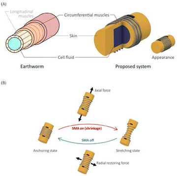
Earthworms are unique subterranean organisms. Their entire body is soft, and they can burrow into the soil by performing a movement termed peristaltic locomotion. Peristaltic locomotion is a method of movement in which axially elongating and radially expanding waves are propagated from the front segment to the back. The radially expanding segments anchor the body in the soil, and the elongating segments move forward. The earthworm achieves peristaltic locomotion using its hydrostatic skeleton structure and two types of muscles: longitudinal and circumferential (Fig. 1).A hydrostatic skeleton is a soft skeletal system in which an internal fluid supports the external muscular membrane. One of the characteristics of a hydrostatic skeleton is that owing to the incompressibility of the internal fluid, muscle contraction in one direction produces expansion in other directions. In other words, when an earthworm contracts the circumferential muscles of one node, the diameter of the node decreases, thereby axially pushing the internal fluid. Consequently, the node elongates axially.
The peristaltic locomotion exhibited by earthworms using hydrostatic skeletons has two significant advantages. First, worms can move through a small space. This can be achieved by varying the diameter and length of each segment. When moving through the soil, peristaltic locomotion requires less soil to be moved than in other modes of movement. Second, most of the body surface can be used as a ground contact area. In worms moving peristaltically, all the segments, except for the axially elongated segments, are grounded.
A suitable purpose for developing an earthworm-inspired robot would be to investigate soil conditions with delicate obstacles, such as plant roots. To realize a robot that can dig through the soil like an earthworm, the robot should be miniaturized to the size of an earthworm. Moreover, it should be sufficiently powerful to dig through the soil. Thus far, to the best of our knowledge, no robot that satisfies these conditions has been reported. Solving the trade-off problem of reducing the size of a robot and increasing its power output is challenging. Previously, we developed a single deformable segment with approximately the same size as an earthworm that was capable of generating approximately the same force as the latter.1 We succeeded in developing an actuated segment but not an earthworm robot.
In this study, we developed an earthworm robot that can dig through the soil. We investigated elastomer materials that could be used as the artificial hydrostatic skeleton. Subsequently, we built a prototype earthworm robot and experimented with the soil.
2 Earthworm-inspired soft robots
2.1 Anatomy of earthworms
An earthworm moves through the soil by repeatedly piercing the soil with its thin pointed head. Then, it inflates its head to create a space.2 An adult earthworm weighing approximately 10 g has a reported maximum force of 1 N to thrust its head in the direction of travel, and a force of approximately 1 N to radially expand its burrow.3 Earthworms can also feed on soil; however, a comparison of their feeding rate and daily movement rate suggests that earthworms achieve soil movement by peristaltic movement rather than feeding.4 Therefore, in this study, we assumed that the migration of earthworms in soils is not affected by their feeding mechanisms.Some studies have also focused on the mechanical properties of the soil rather than the earthworm output. Ruiz et al. simulated the relationship between the ease of penetration into the soil and the soil moisture and clay content, the apex angle of the conical head, and so on.2 The simulations suggest that with an increase in the moisture content and a decrease in the clay content, soil can easily be penetrated, as long as it is not saturated. However, the apical angle of the head has little effect on the ease of penetration.
2.2 Conventional earthworm robots
Prototype robots that mimic worms of various scales and configurations have been proposed (Table 1). However, no robots can move while digging into the soil. Liu et al. developed a prototype earthworm robot that could anchor to tunnel walls in soil using an origami structure.5 This robot could move in a trench of compacted soil but not in a buried area of uncompacted soil.| Actuator | Body structure | Diameter (mm) | Axial elongation | Movement in soil | Cite | |
|---|---|---|---|---|---|---|
| Real earthworms | Biological muscle | Hydrostatic skeleton | −(10) | −(1) | ° | 3 |
| Earthworm robots | SMA | Silicone shell | °(10) | × | ° | 6 |
| SMA | Mesh tube | ×(22) | ° | × | 7 | |
| Pneumatic actuator | Silicone tube | ×(20) | ° | × | 5 | |
| Pneumatic actuator | Silicone tube and O-ring | ×(35) | ° | × | 8 | |
| Servomotor and cable | Mesh body | ×(206) | ° | ° | 9 | |
| Single servomotor and tendons | Rubber skin | ×(76) | × | ° | 10 | |
| DC geared motor | Origami ball and leaf spring | ×(88) | × | ° | 11 | |
| DEA | Rigid rings | ×(30) | ° | × | 12 | |
| DEA | Rigid plate | ×(20) | ° | × | 13 | |
| Voice coil actuator | Silicone shell | ×(54) | ° | × | 14 | |
| Sea floor exploration | Pneumatic cylinder | Rubber tube | ×(150) | ° | × | 15 |
| Lunar exploration | DC motor | Pantograph | ×(130) | × | ° | 16 |
| Planetary exploration | Stepper motor | Pantograph | ×(130) | × | ° | 17 |
| Pipe inspection | Pneumatic actuator | Natural rubber and coil spring | °(10) | ° | × | 18 |
| Pneumatic actuator | Natural rubber and coil spring | ×(15) | ° | × | 19 | |
| Pneumatic actuator | Natural rubber and coil spring | ×(50) | ° | × | 20 | |
| Medical endoscope | Pneumatic actuator | Silicone and fiber | ×(15) | ° | × | 21 |
| SMA and PDMS spring | Polyacetal tube | ×(15) | × | ° | 22 |
Several robots use shape memory alloy (SMA) actuators to reproduce worm-scale robots.6,7 An SMA is similar to biological muscles in that it contracts linearly. An SMA wire actuator contracts when heated. Generally, it is driven by a power supply connected to both ends of the SMA, which generates heat using resistive heating when a current is passed through it. SMAs require less space when mounted on a robot and can be installed inside or outside the robot. Therefore, an SMA is a relatively easy actuator that mimics the muscular arrangement of living organisms. Seok et al. developed a prototype robot that mimicked the peristaltic motions of an earthworm using an SMA and mesh tubes.7 The robot could extend axially by contracting the SMA wrapped around the circumference of its torso. This robot is unsuitable for moving in the soil because the soil penetrates the mesh tubes. By contrast, Menciassi et al. developed a prototype robot with an axial arrangement of SMAs. This robot was approximately 10 mm in diameter, which is approximately the size of an earthworm. However, the robot could not exert an axial extensional force. Consequently, it could not easily dig through the soil. Horchler et al. developed a prototype peristaltic robot using a motor and cable.9 This giant worm-like robot had a maximum diameter of approximately 200 mm; therefore, it could not dig through the soil using peristaltic locomotion.
Several robots, such as an earthworm robot that uses pneumatic actuators, have achieved peristaltic locomotion with body structures that are different from those of earthworms.5,8 Pneumatic actuators require an air tube per section. As such, worm robots that require multiple nodes and multiple air tubes are therefore not suitable for moving in the soil. Next, a dielectric elastomer actuator (DEA)-based earthworm robot has been proposed.12,13 This earthworm robot can extend axially by placing a circular DEA perpendicular to the axis. A DEA requires a high voltage of 1000 V or more to operate. However, high voltages cannot easily be cyclically supplied to a robot moving in the soil. As the extension of these robots is less than 1 mm, they cannot dig through the soil. Other types of robots include those using voice coil actuators, plate springs, and motors, all of which are large with diameters of 50 mm or more.
Subsurface exploration robotics is a field closely related to subterranean mobility.15–17 In both fields, robots have a screw or drill in the front used to dig into the earth. These robots are large in scale and aim to scrape excavated soils off the ground. They are significantly different from the minimally invasive soil moving aimed at in this study.
Owing to the efficacy of peristaltic motion, robots can easily move inside pipes18–20 and the body.21,22 These studies also used pneumatic actuators, which are not suitable for driving in soil.
Conventional earthworm robots have not been able to travel in the soil for the following reasons: first, their large diameter requires a large propulsive force to overcome friction, and second, there is an insufficient mechanism to hold the body in place in the tunnel. In this study, we designed a robot to address these limitations. Concerning the power source, our robot has actuators driven by electrical energy, which are relatively easy to provide using a battery in the future. In the experiments, we supplied energy from outside the robot using extremely thin cables. An SMA was attached to a surface of the robot. Unlike pneumatic actuators and DEAs, SMAs do not require thick air or high-voltage wires.
Concerning the challenge of anchoring in the soil, earthworm robots have shapes that facilitate the generation of a radial force and bristles that enable them to move in one direction. A significant challenge in the movement of earthworm robots is that the nodes that hold their body in place in the soil slip backward, impairing movement efficiency. Some studies have focused on the ability of earthworm robots to immobilize themselves in the soil. Several analytical studies have shown that, for an earthworm robot to advance efficiently by peristaltic locomotion, the body must not slip against the environment.9,23 Kandhari et al. showed that depending on the pattern of the peristaltic motion, the surface of the body must exert anisotropic friction for the robot to move forward.24 Earthworms exploit anisotropic friction by generating backward-facing bristles on their body surfaces. Several studies have attempted to analyze the bristles of earthworms. Menciassi et al. increased the efficiency of a robotic movement by installing a microscale hooked metal plate on a worm robot.6 Liu et al. demonstrated that by using an origami structure, an earthworm robot could be anchored to a compacted soil wall.5 The robot in this paper also incorporates a structure that mimics bristles.
Our pilot study provided a single module of a hydrostatic skeleton with a high axial push-out force.1 The prototype was a cylindrical chamber 10 mm in diameter. It was filled with water and could achieve 60% elongation in the longitudinal direction. It exerted a force of approximately 2 N. These values are comparable to those of living earthworms with similar diameters in terms of the elongation force. The deformable segment of our prototype contracts radially but does not expand. For the earthworm robot to switch between fixation and non-fixation by pressing its body against the wall of the tunnel in the soil, the radial constriction must be maximized. The prototype segment has a simple cylindrical shape. The only part that shrinks radially is the SMA-wrapped part; neither end of the segment can shrink in the radial direction. The geometry of the prototype segment is unsuitable for anchoring the robot's body because the actively undeformed parts might become stuck in the tunnel.
3 3D printed hydrostatic skeleton
3.1 Basic concept
We proposed an artificial hydrostatic skeleton (hydrostat) segment (Fig. 1). The artificial hydrostat comprised a soft cylindrical chamber that contained incompressible liquid (water) and was deformable using artificial muscles with SMA actuators. Only the circumferential muscles of the earthworm were reproduced, whereas the longitudinal muscles were omitted, and the recovery force of the elastic material was used. Features not found in previous studies included the following: (1) 3D printed thin-walled and barrel-shaped segments and (2) bio-inspired bristles for anisotropic friction.To achieve miniaturization and large deformation, we utilized a 3D printer for low-hardness rubber. The minimum hardness of silicone rubber used in studies on soft robotics is approximately 10 A shore hardness, which is insufficient to realize robotic earthworms. We utilized a special 3D printer (M3DS-SA5, MITS Electronics, Japan) capable of layering flexible resins with a shore hardness of A2. This printer was also useful for creating small, thin-walled, hollow shapes. If miniaturization approached the size of real earthworms, the same burrowing mechanics could be applied.
When moving on the ground or in a pipe, the amount of elongation and contraction is important for locomotion because resisting forces are absent. However, in subterranean locomotion, the force to push the soil away is important, and according to previous studies, the hydrostatic skeleton exerts a large elongation force.1
3.2 Soft materials for hydrostatic skeleton
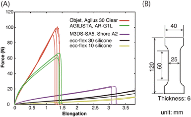
The material properties required to fabricate earthworm-inspired robots include low hardness and tensile strength. We analyzed the disparity between the low-hardness 3D printing materials used in this study and both the existing rubber-like materials for 3D printing and two-component silicone rubber. As shown in Table 2, five materials are used as samples: a rubber-like material for 3D printing, two major rubber-like materials for 3D printing, and two silicone rubbers used for cast moldings.| No. | Type | Manufacturer | Material |
|---|---|---|---|
| 1 | 3D printing (M3DS-SA5) | MITS electronics | Shore A2 rubber-like resin |
| 2 | 3D printing (objet Connex3) | Stratasys Ltd | Agilus 30 clear |
| 3 | 3D printing (AGILISTA-3200) | KEYENCE Corp. | AR-G1L |
| 4 | Platinum-catalyzed silicone | Smooth-On, Inc. | Ecoflex 10 |
| 5 | Platinum-catalyzed silicone | Smooth-On, Inc. | Ecoflex 30 |
We performed tensile tests to determine the properties of the soft materials for use in the earthworm robot. Fig. 2(B) shows an overview of the specimens used in the tensile tests. The JIS standard was used to perform the tensile tests (tension test: JIS K 6251). Fig. 2(A) shows the results of tensile tests.
Two platinum-cured silicone rubbers that cannot be 3D printed have sufficient elongation and strength, although the realization of tiny hollow structures is challenging. UV-curable rubber-like resins used in inkjet 3D printers are harder than silicone rubber and tear at a lower elongation rate. UV-cured soft materials are highly viscous. By comparison, the material employed in this study is as soft as silicone rubber, yet it is 3D printable and can be used to create extremely fine hollow structures and protrusions.
4 Soft burrowing robot
4.1 Earthworm-inspired design
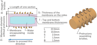
Miniaturization, large deformation, and anchoring bodies in soil tunnels have been the challenges of previous studies. To address these issues, we proposed a design with multiple hydrostatic segments connected in series. Fig. 3 shows a schematic design of the soft burrowing robot and an overall photograph of the actual prototype robot. The body of the robot consisted of four segments. One segment, covered with spikes, was squeezed and elongated with a single SMA wire. Finally, we designed the segments with a diameter-to-length aspect ratio of approximately 1![[thin space (1/6-em)]](https://www.rsc.org/images/entities/char_2009.gif) :
:![[thin space (1/6-em)]](https://www.rsc.org/images/entities/char_2009.gif) 2 (Fig. 4). The hydrostatic segment measures 22 mm in length and 10 mm in diameter, not including the spikes. We considered a suitable diameter of 10 mm for mimicking an actual earthworm. In preliminary experiments, we also realized prototypes of relatively narrower segments and found that they were likely to buckle. The robot had a conical head at the front and a conductor guide at the rear to bundle the cables that were connected to the SMA. The conductor guide collected the cables from the body and ejected them into the rear of the robot.
2 (Fig. 4). The hydrostatic segment measures 22 mm in length and 10 mm in diameter, not including the spikes. We considered a suitable diameter of 10 mm for mimicking an actual earthworm. In preliminary experiments, we also realized prototypes of relatively narrower segments and found that they were likely to buckle. The robot had a conical head at the front and a conductor guide at the rear to bundle the cables that were connected to the SMA. The conductor guide collected the cables from the body and ejected them into the rear of the robot.
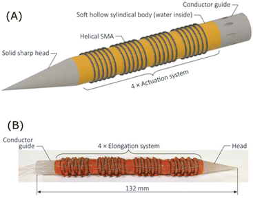 | ||
| Fig. 3 Overview of the earthworm-inspired soft burrowing robot. (A) CAD model of the multi-segment structure without spikes. (B) Prototype robot. | ||
The improvement related to generating a propulsive force is thin protrusions that mimic the bristles of earthworms. The tips of the protrusions were cut at an angle to achieve anisotropic friction on the surface of the segment. These spikes were used to secure the SMA wire wrapped around the segment. In the case of a smooth cylinder without spikes, repeated expansion and contraction resulted in undesired misalignment of the circular SMA wire. We used coiled SMA wires (Biometal BMX150, Toki Corp. Japan.) wound around the segment for nine laps.
The barrel shape, which is not found in earthworms, is an important improvement in the production of soft robots. Both ends of the segment cannot be thinned because the SMA wire cannot be wrapped around them, and the caps are in place. In the initial cylindrical prototype, when the SMA contracted, its ends became the largest in diameter and stuck in the tunnel. The barrel shape enabled the center of the segment to be in contact with the soil tunnel before deformation. However, it could be detached when it became thin due to the contraction of the SMA.
4.2 Finite element method modeling
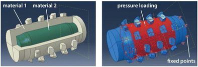
We built a 3D finite element method (FEM) model to further investigate the deformation behavior of the hydrostatic segment. We compared a cylindrical hollow structure with spikes filled with an incompressible material and an empty filling at two different wall thicknesses. They were also compared to solid structures. All the models had the same external dimensions, varying only in their internal structures.The FEM analysis was performed using SIMULIA Abaqus CAE. The segments were modeled using ten-node tetrahedral elements (C3D10). The material model of the segment body was set as an elastic material with a Young's modulus of 0.106 MPa and a Poisson's ratio of 0.2. The incompressible fluid inside the segment was simulated using an extremely soft elastic material with a Young's modulus of 0.0106 MPa and a Poisson's ratio of 0.48. The fluid was approximated to a solid material in this experiment because of the challenge of accurately operating the coupling between the soft material and fluid. The Poisson's ratio of the segment body was set low to focus on the deformation of the fillings in this experiment.
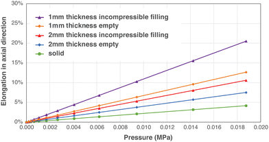
In the simulation, one end face of the segment was fixed on a plane and the displacement of the other end was measured. A uniform pressure load distribution of 0.01875 MPa was applied to the cylindrical surface of the segment (Fig. 5). This pressure simulated the contraction force of the wrapped SMA. Models with wall thicknesses of 1 mm and 2 mm and a common end wall thickness of 1.5 mm were prepared. The displacement of the center point on the end surface was measured during deformation.
The simulation results of the five models are presented in Fig. 6. In addition, Fig. 7 shows the state before and after the deformation of the 2 mm-thickness body with incompressible filling. The results show that, compared with a structure whose contents are empty, a structure whose contents are filled with soft material can convert pressure from the surroundings into elongation. In addition, elongation in the long-axis direction is greater for thinner walls. However, the wall thickness cannot further be reduced. This is related to the strength against breakage and the accuracy of the 3D printer. In our prototyping, the 3D printing of the 1 mm-thick segments occasionally failed, and the tension of the SMA wire often resulted in tears. Therefore, the segments used for the multi-segment soft robot in this study were 2 mm wall-thick, water-filled segments.
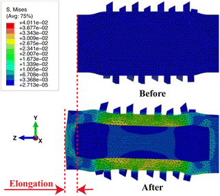 | ||
| Fig. 7 Before and after the deformation of a 2 mm thickness segment with incompressible filling. The colour scale indicates Von Mises stress values. | ||
5 Experiments
5.1 Burrowing forces
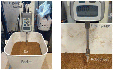
The head of the robot was conical with a 15° angle at the tip and a total length of 20 mm. Basic experiments were conducted to determine the force required to burrow into the soil based on the size of the soft burrowing robot.The robot head was attached to the tip of a digital force gauge (FGPseries, Nidec-Shimpo, Japan). The head was lowered using a force gauge stand and thrust into the soil (Fig. 8). The head was thrust to a depth of 15 mm below the ground surface, and the force applied to the head was measured. The speed at which the actuator system extended axially was 20 mm min−1.
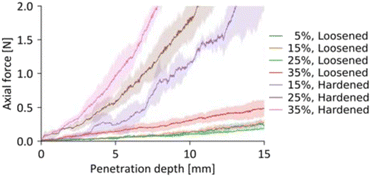
The soil was a heat-treated horticultural soil (No. 050952, TACHIKAWA HEIWA NOUEN CO., Ltd). The soil used in the experiment was 8 kg and was placed in buckets. The amount of moisture and the compaction rate of the soil affected the force exerted on the head. In this experiment, the prepared soil had 5%, 15%, 25%, and 35% water content relative to the mass. Uncompacted soil and that compacted to 85% volume were also prepared. However, soil with a water content of 5% was not prepared, as it was challenging to compact the soil because of its low water content.
Fig. 9 shows the results of the experimental thrust of the robot head into the soil. The results of the experiment showed that for uncompacted (loosened) soil, the head could be inserted 15 mm with a force of 6 N or less at any moisture content. In other words, the earthworm robot cannot easily dig rapidly through the compacted soil. However, within the range 5–10 mm, the head of the robot could penetrate the soil even with a force of 2 N. We predict that the speed of travel of the robot will be significantly slower in compacted soil.
5.2 Methods
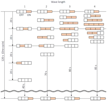
According to the measurement in Section 5.1, an uncompacted soil with a moisture content of 25% by weight exhibiting the lowest penetration force was adopted. The box containing the soil was sufficiently large; thus, the effect of the wall was negligible.Fig. 10 shows the four peristaltic movement patterns used in the experiments. The difference between each operating pattern was the number of segments that were simultaneously activated. At each phase in the pattern, the SMA was contracted at a voltage of 5 V for 20 s. This value indicated the time required for the SMA to contract fully. As the number of segments that contract simultaneously increased, the time of one cycle decreased. In all the patterns, a period of contraction and propulsion was followed by a break period for cooling. Therefore, one cycle had a total duration of 120 s. The break period prevented the SMA from becoming extremely hot and damaging the skin of the robot.
Two experiments were conducted wherein the robot was at different depths in the soil. In the first, the top of the robot's body was at a depth of 0 mm, and in the second, the top was at a depth of 5 mm in the soil (Fig. 11). The robot could not be observed if it was completely buried in the soil. Therefore, we experimented with the condition that the robot's body was slightly exposed at a depth of 0 mm to observe its movement. Then, we operated the robot when it was completely buried in the soil to demonstrate that it was capable of digging through the soil.
 | ||
| Fig. 11 Position of the worm robot in the experiment. (A) Semi-buried depth of 0 mm. (B) Fully-buried, depth of 5 mm. | ||
5.3 Peristaltic experiment in semi-buried conditions
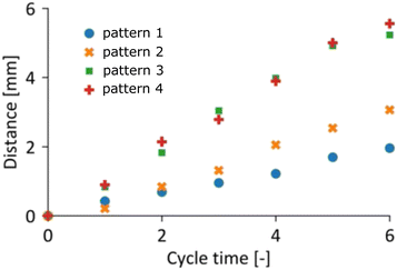
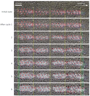
The soft burrowing robot was tested at a depth of 0 mm, and it exhibited forwarding locomotion in all four locomotion patterns. As shown in Fig. 12, a pattern wherein several segments were simultaneously activated results in a relatively long travel distance. In pattern 4, the earthworm moved 0.93 mm per cycle at a speed of 0.46 mm min−1 (Fig. 13).Friction and slippage between the soil and robot's surface are critical for propulsion. The experimental results show that anisotropic friction is generated by spikes that mimic bristles. Observations showed that the soil was fragile and collapsible, and the grains that made up the soil rolled and filled the spaces between the spikes. In other words, a subterranean robot is in an extremely different situation than a robot that moves peristaltically in a smooth pipe with a constant diameter. The soil condition, such as the amount of moisture and porosity, affects the force of penetration and also the anchoring capacity.
5.4 Peristaltic experiment in a fully buried condition
The earthworm-inspired robot was positioned in the soil, and it performed six cycles of peristaltic movements. We measured the robot's position before it was buried in the soil, and the soil was removed after all the cycles. Our experiments confirm that the earthworm robot digs through the soil in peristaltic movement patterns as shown in Table 3. By using pattern 4, which had the longest travel distance, the distance was measured when the robot performed 6 and 12 cycles of peristaltic movement as shown in Table 4. The experimental results showed that the earthworm robot could propel at approximately 3 mm per cycle and a speed of 1.5 mm min−1 in the soil.| Pattern | Travel distance (mm) |
|---|---|
| 1 | 1.2 |
| 2 | 2.4 |
| 3 | 2.4 |
| 4 | 2.7 |
| Trial | 1–6 Cycles (mm) | 7–12 Cycles (mm) |
|---|---|---|
| 1 | 2.5 | 2.6 |
| 2 | 2.0 | 4.1 |
| 3 | 2.3 | 3.5 |
| 4 | 3.7 | 5.1 |
| 5 | 3.1 | 1.7 |
| mean ± s.d. | 2.7 ± 0.6 | 3.4 ± 1.2 |
6 Conclusions
We constructed an earthworm-inspired soft-burrowing robot with a 3D-printed artificial hydrostatic skeleton. The robot had a multi-segment structure and performed peristaltic motions driven by SMA wires. Using a 3D printer for low-hardness soft materials, we modeled a thin-walled hollow structure with fine spikes. Through tensile testing, we showed that the 3D printed soft material was more deformable than the silicone rubber and rubber-like resins used in other soft robots. Through finite element simulations, we showed that elongation was achieved by combining thin walls and incompressible contents. Hydrostatic segments, which converted radial contraction into longitudinal elongation, were filled with an incompressible liquid (water). The proposed earthworm-inspired soft subsoil robot consisted of four segments and exhibited peristaltic motions. The diameter of the multi-segment earthworm robot, excluding the spikes, was 10 mm. We determined the soil conditions in which the required force of penetration into the soil was small. The peristaltic pattern enabled the robot to propel itself to a depth of 5 mm in the soil. In experiments comparing several peristaltic patterns, we found that the distance traveled was greater in relatively fast peristaltic patterns than those wherein several segments were simultaneously activated. The results suggest that moving in granular soil, which is fragile and collapsible, requires a design concept that differs from that of a robot moving in a pipe. The miniaturized hydrostatic segment with spikes proposed in this study is a design solution.Several limitations and challenges were identified in this study. The proposed robot had a slow traveling speed of approximately 1.5 mm min−1 and needs improvement to efficiently convert peristaltic motion into locomotion. Another noticeable enhancement would be the addition of steering capability to the robot, which currently only moved in straight lines. One strategy involves embedding several longitudinal actuators and contracting them independently. Controlling soil conditions is also important for propelling; earthworms appear to alter the condition of the surrounding soil by secreting mucus. Thus, an appropriate liquid-secreting earthworm robot may be a research topic for future studies. We can assume a tethered and retractable form to prevent a situation where the robot is lost in the soil and never comes back. Alternatively, enabling the robot to stand-alone using built-in batteries and control devices is another major future challenge.
Conflicts of interest
The authors declare that they have no conflicts of interest.Acknowledgements
This work was supported by JSPS KAKENHI Grant Numbers JP18H05466 and JP20K19890.Notes and references
- K. Matsushita, M. Ikeda, K. Or, R. Niiyama and Y. Kuniyoshi, IEEE/SICE International Symposium on System Integration (SII), 2022, pp. 47–52 Search PubMed.
- S. Ruiz, D. Or and S. J. Schymanski, PLoS One, 2015, 10, e0128914 CrossRef PubMed.
- K. Quillin, J. Exp. Biol., 2000, 203, 2757–2770 CrossRef CAS PubMed.
- K. J. Quillin, J. Exp. Biol., 1999, 202, 661–674 CrossRef PubMed.
- B. Liu, Y. Ozkan-Aydin, D. I. Goldman and F. L. Hammond, 2nd IEEE International Conference on Soft Robotics (RoboSoft), 2019, pp. 828–833.
- A. Menciassi, S. Gorini, G. Pernorio, L. Weiting, F. Valvo and P. Dario, IEEE International Conference on Robotics and Biomimetics (ROBIO), 2004, pp. 274–278.
- S. Seok, C. D. Onal, K.-J. Cho, R. J. Wood, D. Rus and S. Kim, IEEE/ASME Transactions on mechatronics, 2012, 18, 1485–1497 Search PubMed.
- A. A. Calderón, J. C. Ugalde, J. C. Zagal and N. O. Pérez-Arancibia, IEEE international conference on robotics and biomimetics (ROBIO), 2016, pp. 31–38.
- A. D. Horchler, A. Kandhari, K. A. Daltorio, K. C. Moses, J. C. Ryan, K. A. Stultz, E. N. Kanu, K. B. Andersen, J. A. Kershaw and R. J. Bachmann, et al. , Soft Robot., 2015, 2, 135–145 CrossRef.
- B. Winstone, T. Pipe, C. Melhuish, M. Callaway, A. C. Etoundi and S. Dogramadzi, 6th IEEE International Conference on Biomedical Robotics and Biomechatronics (BioRob), 2016, pp. 449–456.
- H. Fang, Y. Zhang and K. Wang, Bioinspiration Biomimetics, 2017, 12, 065003 CrossRef PubMed.
- H. Choi, S. Ryew, K. Jung, H. Kim, J. W. Jeon, J. Nam, R. Maeda and K. Tanie, IEEE/RSJ International Conference on Intelligent Robots and Systems (IROS), 2002, pp. 1730–1735.
- K. Jung, J. C. Koo, Y. K. Lee and H. R. Choi, et al. , Bioinspiration Biomimetics, 2007, 2, S42 CrossRef PubMed.
- M. P. Nemitz, P. Mihaylov, T. W. Barraclough, D. Ross and A. A. Stokes, Soft Robot., 2016, 3, 198–204 CrossRef PubMed.
- N. Tadami, M. Nagai, T. Nakatake, A. Fujiwara, Y. Yamada, T. Nakamura, H. Yoshida, H. Sawada and T. Kubota, IEEE/RSJ International Conference on Intelligent Robots and Systems (IROS), 2017, pp. 4950–4956.
- T. Nakatake, M. Konno, A. Mizushina, Y. Yamada, T. Nakamura and T. Kubota, IEEE International Conference on Advanced Intelligent Mechatronics (AIM), 2016, pp. 407–412.
- H. Omori, T. Murakami, H. Nagai, T. Nakamura and T. Kubota, IEEE International Conference on Robotics and Automation (ICRA), 2011, pp. 649–654.
- M. Kamata, S. Yamazaki, Y. Tanise, Y. Yamada and T. Nakamura, IEEE International Conference on Advanced Intelligent Mechatronics (AIM), 2017, pp. 309–314.
- T. Kishi, M. Ikeuchi and T. Nakamura, IEEE/RSJ International Conference on Intelligent Robots and Systems (IROS), 2013, pp. 3297–3302.
- Y. Mano, R. Ishikawa, Y. Yamada and T. Nakamura, IEEE/RSJ International Conference on Intelligent Robots and Systems (IROS), 2018, pp. 8177–8183.
- H. Heung, P. W. Chiu and Z. Li, IEEE international conference on robotics and biomimetics (ROBIO), 2016, pp. 497–502.
- M. E. Karagozler, E. Cheung, J. Kwon and M. Sitti, The First IEEE/RAS-EMBS International Conference on Biomedical Robotics and Biomechatronics, BioRob 2006., 2006, pp. 105–111.
- K. A. Daltorio, A. S. Boxerbaum, A. D. Horchler, K. M. Shaw, H. J. Chiel and R. D. Quinn, Bioinspiration Biomimetics, 2013, 8, 035003 CrossRef PubMed.
- A. Kandhari, Y. Wang, H. J. Chiel, R. D. Quinn and K. A. Daltorio, Soft Robot., 2021, 8, 485–505 CrossRef PubMed.
| This journal is © The Royal Society of Chemistry 2022 |

