
Fabrication of oriented hBN scaffolds for thermal interface materials†
Heng Shenab,
Chao Caiab,
Jing Guoab,
Zhenchao Qianab,
Ning Zhao*a and
Jian Xu*a
aBeijing National Laboratory for Molecular Sciences, Laboratory of Polymer Physics and Chemistry, Institute of Chemistry, Chinese Academy of Sciences, Zhongguancun North First Street 2, Beijing, 100190, P. R. China. E-mail: zhaoning@iccas.ac.cn; jxu@iccas.ac.cn
bUniversity of Chinese Academy of Sciences, Beijing, 100049, P. R. China
First published on 29th January 2016
Abstract
Thermal interface materials are widely used in thermal management, and usually require a high thermal conductivity, low coefficient of thermal expansion (CTE) and adequate softness. Herein, hBN/PDMS composites are fabricated by the infiltration of a PDMS prepolymer in the hBN scaffolds followed by a thermal curing process. The scaffolds are prepared by an ice templating method with hBN microplatelets, leading to a good alignment of hBN platelets along the z direction in the PDMS matrix. This unique structure results in a high thermal conductivity, which is about 3 times higher than that of the composites fabricated by a casting method, and the thermal conductivity is as high as 1.4 W m−1 K−1 along the z direction at ∼20 wt% of hBN microplatelets. The composites also possess low CTEs which are <100 ppm K−1 along the z direction and maintain an adequate softness.
Introduction
The high power and performance of devices cause elevated temperatures which inevitably negatively affect efficiency and safety. Thermal interface materials (TIMs) which can dissipate heat efficiently attract significant attentions in thermal management applications.1 Thermal conductive composites composed of a polymer and inorganic fillers such as Al2O3, AlN, SiC and Si3N4, are the most widely used TIMs due to their easy processability and low cost.2–5 Recently, carbon materials have been widely used in the fabrication of heat spreaders because of their super high thermal conductivity,6–8 however, the excellent electrical conductivity may limit their applications in microelectric devices. Hexagonal boron nitride (hBN) is a new type of promising thermal conductive filler owing to its excellent thermal conductivity and stable chemical properties. In addition, its electrical insulating property makes it more appropriate for TIMs used in electronics.9 As an analogue to graphite, the hBN microplatelet has a flake structure and shows a conspicuous anisotropic thermal conductivity. The in-plane thermal conductivity of the hBN microplatelet (∼600 W m−1 K−1) is about 30 times that of the out-of-plane thermal conductivity.10 Although many hBN/polymer composites have been reported, the thermal conductivity of these materials are usually not satisfactory.11–14Surface modification of hBN is a common method to enhance the thermal conductivity, but the improvement is very limited.15–20 The orientation of hBN in the polymer matrix has a more profound effect on the thermal conductivity. The well aligned hBN fillers in the polymer matrix result in a higher thermal conductivity along the alignment direction.10,21–31 Due to the high aspect ratio of hBN platelets, the orientation along the horizontal direction is easier to realize using several simple methods including stretching,22 doctor blading,24–26 vacuum filtration27 and oscillatory shearing.28 However, in practical applications, the TIMs usually should have a high thermal conductivity along the thickness direction (z direction) which requires perpendicular orientation of the hBN fillers. Magnetic alignment has been successfully employed to achieve highly thermal conductive hBN/polymer composites along the z direction.10,21,23,29,31 However, this strategy seems complicated because the hBN platelets need to be decorated with superparamagnetic iron oxide nanoparticles and the magnetic field needs to be well controlled. A high voltage electric field was also used to orient the platelets,32 however, a high voltage implies safety risks. Therefore, the facile fabrication of well ordered hBN/polymer composites with a high thermal conductivity along the z direction is still a challenge.
In this study, we developed a facile way of fabricating hBN/PDMS composites with a good vertical orientation of hBN microplatelets. The hBN/PDMS composites were prepared by vacuum infiltration of a PDMS prepolymer into the hBN scaffolds and then thermally cured. The results show that the thermal conductivity of hBN/PDMS composites with ∼20 wt% hBN fillers was as high as 1.4 W m−1 K−1 along the z direction, almost four-fold that of the composites fabricated by the conventional casting method. The hBN/PDMS composites also had a low coefficient of thermal expansion (CTE) (<100 ppm K−1) along the z direction and adequate softness. All these outstanding properties imply that the hBN/PDMS composites prepared are ideal candidates for TIMs.
Experimental section
Materials
hBN microplatelets (−325 mesh powder, 99.5%) and sodium metasilicate (Na2SiO3) were purchased from Alfa Aesar. Polyvinylpyrrolidone (PVP K-30) was purchased from Sinopharm Chemical Reagent Co., Ltd. The PDMS prepolymer (Sylgard 184) was purchased from Dow Corning.Preparation of 3D hBN scaffolds
The ice templating procedure is similar to previous reprots.33,34 Typically, 1.5, 2 and 2.5 g of hBN microplatelets, respectively, were dispersed in 8 mL of deionized water with 0.1 g of PVP as the dispersant. After sonication for 30 min, Na2SiO3 (5 wt% of the weight of hBN) was added into the dispersion and the mixture was sonicated for another 10 min. The hBN suspension was poured into a columniform polythene mold with a diameter of 25 mm placed on the top of a cold rod, which was cooled to −60 °C by refrigerating fluid. After the suspension was frozen completely, the resultant sample was freeze-dried for 24 h. Finally, the freeze-dried sample was calcined at 700 °C for 1 h to remove PVP and the 3D hBN scaffolds were obtained, which were denoted as Scaffold a1, a2 and a3, respectively. The samples frozen at −196 °C were also prepared and denoted as Scaffold b1, b2 and b3.Preparation of hBN/PDMS composites
The hBN scaffolds were put into the degassed PDMS prepolymer (base/curing agent 10![[thin space (1/6-em)]](https://www.rsc.org/images/entities/char_2009.gif) :1, wt/wt), followed by degassing in a vacuum oven at 30 °C for 2 h to make sure the prepolymer infiltrated the scaffolds completely. After that, the scaffolds were taken out and thermally cured at 80 °C for 6 h. The composites fabricated with Scaffolds a1, a2 and a3 were denoted as Composite A1, A2 and A3, respectively, and denoted as Composite B1, B2 and B3 for Scaffolds b1, b2 and b3. The content of the hBN microplatelets in the composites was calculated according to the density and the mass measured. For comparisons, hBN/PDMS composites were fabricated by a simple casting as follows: hBN scaffolds were pulverized and the powder was mixed with PDMS prepolymer. After stirring vigorously, the mixtures were degassed and thermally cured at 80 °C for 6 h. The composites were denoted as Composite C1, C2 and C3.
:1, wt/wt), followed by degassing in a vacuum oven at 30 °C for 2 h to make sure the prepolymer infiltrated the scaffolds completely. After that, the scaffolds were taken out and thermally cured at 80 °C for 6 h. The composites fabricated with Scaffolds a1, a2 and a3 were denoted as Composite A1, A2 and A3, respectively, and denoted as Composite B1, B2 and B3 for Scaffolds b1, b2 and b3. The content of the hBN microplatelets in the composites was calculated according to the density and the mass measured. For comparisons, hBN/PDMS composites were fabricated by a simple casting as follows: hBN scaffolds were pulverized and the powder was mixed with PDMS prepolymer. After stirring vigorously, the mixtures were degassed and thermally cured at 80 °C for 6 h. The composites were denoted as Composite C1, C2 and C3.
Characterization
The scanning electron microcopy (SEM) test was carried out on a JSM-7500F (JEOL, Japan) at an accelerating voltage of 5 kV. The SEM-EDS test was carried out at 15 kV. Powder X-ray diffraction (XRD) patterns were performed on an Empyrean X-ray diffractometer using Cu Kα radiation (PANalytical, Netherlands). The thermal diffusivity (α) of the composites was investigated by using a laser-flash diffusivity instrument LFA 447 (NETZSCH, Germany). The specimens were prepared to be 12.7 mm in diameter and 1–2 mm in thickness and spray-coated with a thin layer of fine graphite powder at both sides. The specific heat (c) was detected by differential scanning calorimetry (DSC) Q2000 (TA Instruments, America) at a heating rate of 10 °C min−1. The density (ρ) was measured by using an automatic density analyzer ULTRAPYC 1200e (Quantachrome Instruments, America). The thermal conductivity was calculated from the equation: λ(T) = α(T) × ρ(T) × c(T), and T was 30 °C. The thermal infrared images were detected by a thermal infrared imager, PCE-TC3 (PCE Instruments, Germany). The CTE of the composites was measured by a thermal dilatometer, DIL 402PC (NETZSCH, Germany), the columniform samples were prepared according to the Al2O3 standard sample with a diameter of 6 mm and a length of 25 mm, and the test was conducted from room temperature to 200 °C with 5 °C min−1. The compression test was performed on a WDT-10 tensile tester (Kaiqiangli Testing Instrument CO., LTD, China). The columniform specimens were loaded in the compression mode with a rate of 2.5 mm min−1.Results and discussion
As shown in Scheme 1, the three dimensional (3D) hBN scaffold was fabricated by a typical ice templating method.33–38 PVP was added into the suspension to improve the dispersibility of hBN in water. In brief, when the hBN suspension was poured into a mold on a precooled rod, ice crystals rapidly nucleated at the bottom of the suspension and parallel ice fingers gradually formed due to the significant temperature gradient. Meanwhile, the hBN microplatelets were repelled by the growing ice fingers and assembled in the cell wall structure into the inter-finger spaces. Because hBN is chemically inert and there is no strong interaction between the microplatelets, Na2SiO3 was incorporated into the system as an adhesive to fix the 3D networks after freeze-drying. PVP was removed through calcination, resulting in the formation of the 3D hBN scaffold.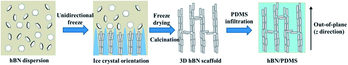 | ||
| Scheme 1 Schematic illustration of the fabrication process of hBN/PDMS composites with the vertical alignment of hBN microplatelets. | ||
The hBN microplatelets had a good flake structure with an average lateral size of 4.1 ± 1.6 μm (Fig. S1†). Fig. 1a and b shows the typical cross section morphology of the resultant 3D hBN Scaffold a2 (using −60 °C) and b2 (using −196 °C), where the ice growth direction is out of the page. It can be seen that the hBN microplatelets form an ordered cell wall structure, and some bridges connecting the adjacent lamellar walls can also be observed. Differently, the wall of Scaffold b2 was much thinner, with a decreased lamellar spacing than that of Scaffold a2. This is because the process of ice-growing is affected by the freezing temperature.34 The lower freezing temperature resulted in more nucleations of ice crystals and thinner ice fingers. The EDS detection reveals that the Na and Si elements existed in the hBN scaffolds, in comparison to the pristine hBN (Fig. S2†), indicating that Na2SiO3 was coated on the surface of hBN. The existence of Na2SiO3 played a critical role in immobilizing the 3D networks of hBN, since the scaffolds could not be obtained by hBN alone under the same condition. The cross section SEM images of the corresponding composites are shown in Fig. 1c and d. We can see that the ordered 3D networks were maintained well after the infiltration of the PDMS prepolymer, and no pores were observed, indicating the complete infiltration of PDMS in the hBN scaffolds. The cross section SEM images along the z direction of Composite A2 are given in Fig. S3,† and further proved the highly anisotropic structure of the hBN scaffold in PDMS. Similar results of other samples are shown in Fig. S4 and S5.† In contrast, the hBN microplatelets arranged in a disordered structure in the composites fabricated by a conventional casting method (Fig. S6†). The calculated content of the fillers was 15.6, 19.8 and 23.7 wt% in hBN/PDMS Composite A1, A2 and A3, respectively (Table S1†). Composite C was fabricated according to the calculated weight fraction of Composite A, and the detected density was 1.16 g cm−3 (15.6 wt%), 1.20 g cm−3 (19.8 wt%), and 1.22 g cm−3 (23.7 wt%), respectively. The density of Composite C matched with that of Composite A, which further supported the conclusion that PDMS completely infiltrated the hBN scaffolds. The photos of Scaffold a2 and Composite A2 are shown in Fig. S7,† the composite could be easily cut into different shapes and thicknesses according to the practical application requirement.
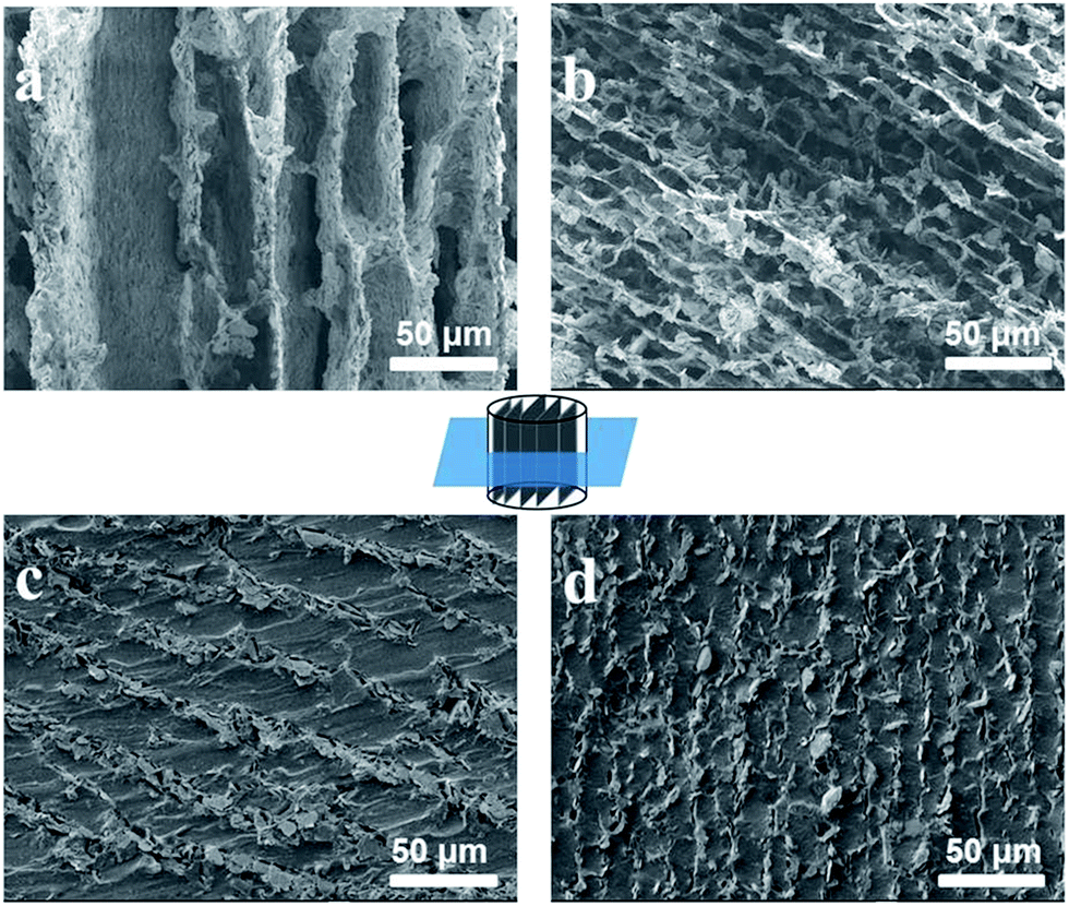 | ||
| Fig. 1 Cross section SEM images of (a) Scaffold a2, (b) Scaffold b2, (c) Composite A2 and (d) Composite B2, in which the z direction is out of the page. | ||
The XRD analysis of the hBN/PDMS composites shown in Fig. 2 gives additional evidence of the alignment of hBN microplatelets. The hBN microplatelets have two characteristic peaks at approximately 26.9° and 41.6°, which are assigned to the (002) and (100) crystallographic planes of hBN, and the ratio of the intensity of the two peaks presents the alignment mode of hBN microplatelets.24,26 For Composite C, prepared by the conventional casting method, the hBN microplatelets are randomly distributed, and the intensity of peak (002) is much higher than that of (100), as shown in Fig. 2a. For Composite A in Fig. 2b fabricated by the ice templating method, however, a decreased (002) peak and an increased (100) peak were observed significantly. The changes suggest that a larger amount of hBN microplatelets oriented vertically in Composite A than in Composite C, indicating the high efficiency of the alignment induced by ice templating. Similar XRD results are also found for Composite B (Fig. S8†).
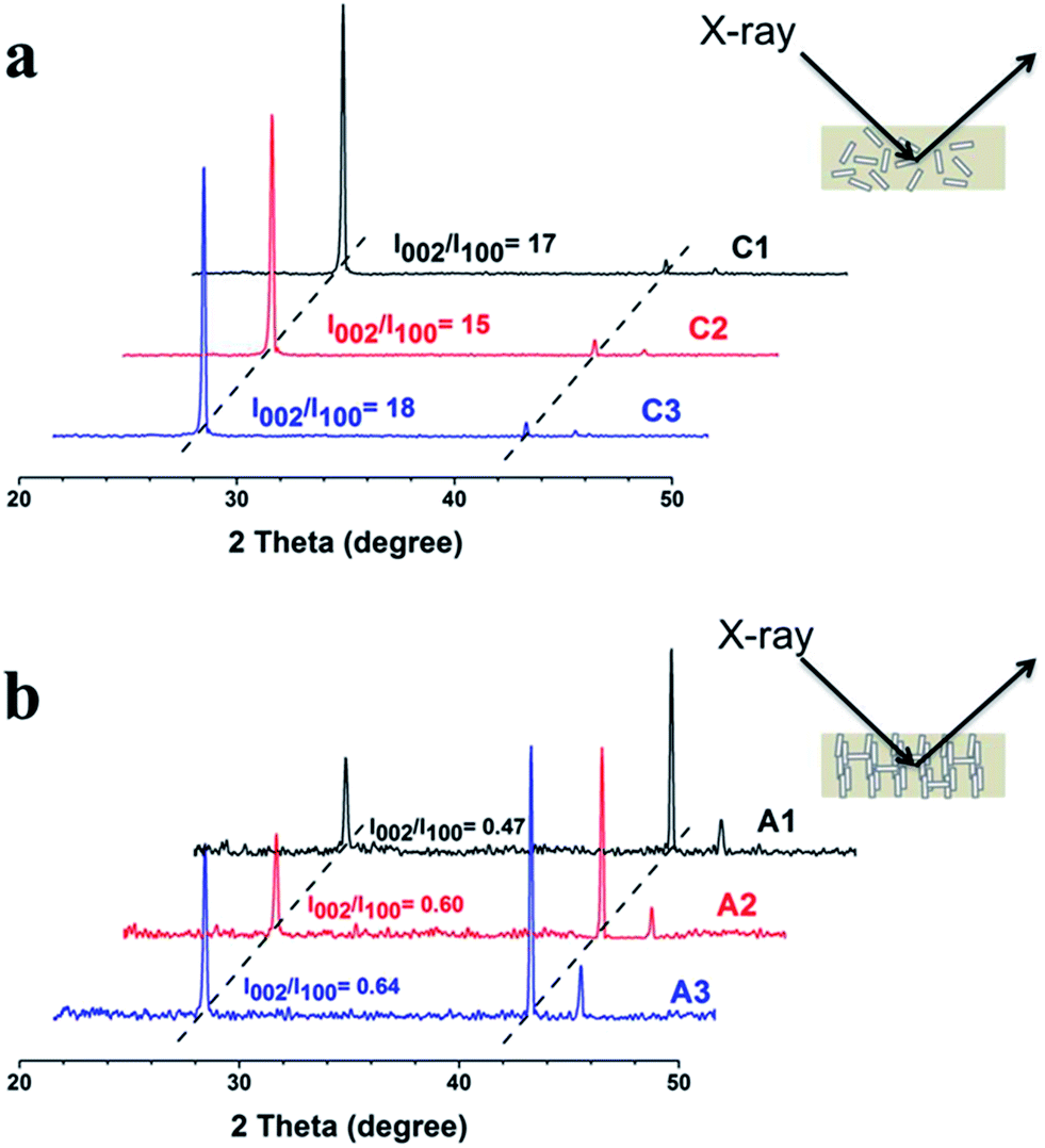 | ||
| Fig. 2 XRD patterns of (a) Composite C and (b) Composite A. | ||
The filler alignment significantly affected the thermal conductivity of the hBN/PDMS composites (Fig. 3). The thermal conductivity of the pristine PDMS was only 0.15 W m−1 K−1. However, the thermal conductivity increased a lot for Composite A. The enhancement, defined as 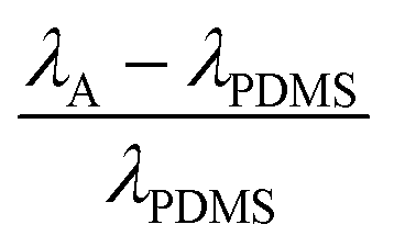 , reached 666%, 840% and 1033% for filler loadings of 15.6, 19.8 and 23.7 wt%, respectively. The thermal conductivity of Composite A increased nearly three-fold compared with that of Composite C with the same filler loading because of the orientation of hBN microplatelets in the PDMS matrix. Direct thermal conductive paths were formed by the hBN walls from the bottom to the top, and the instinctively high in-plane thermal conductivity of the hBN microplatelet was utilized sufficiently. Composite C has a low thermal conductivity along the z direction since the hBN microplatelets were in a disordered arrangement. Schematic diagrams of the heat flow in the composites are shown in Fig. 3b. It should be noted that the introduction of Na2SiO3 on the hBN surface had no obvious influence on the thermal conductivity of hBN (Fig. S9†).
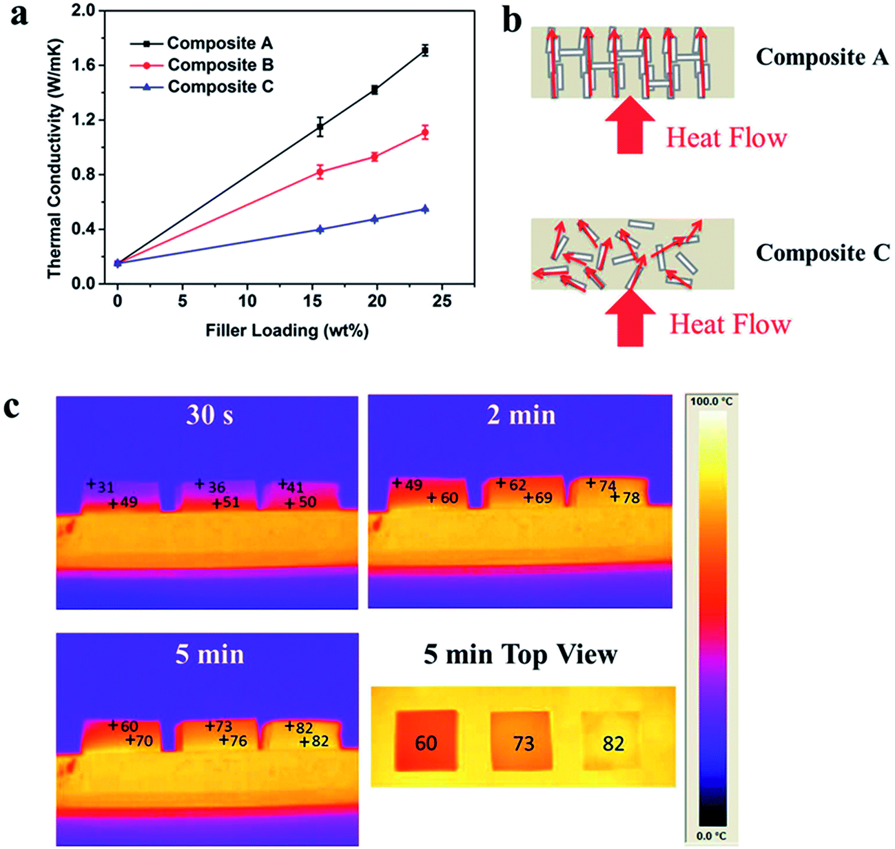 | ||
| Fig. 3 (a) Thermal conductivities of Composite A, B and C as a function of the filler loading. (b) Schematic diagram of the heat flow in Composite A and C. (c) Thermal infrared images of PDMS, Composite C2 and Composite A2 (left to right) at 30 s, 2 min, and 5 min. | ||
For the similar aligned structure, Composite B had a lower conductivity than that of Composite A. The modified effective medium approximation (EMA) was used to analyze the experimental results. This model takes several parameters into consideration, including the thermal conductivity of the filler and matrix, volume fraction, filler shape and orientation, and thermal boundary resistance (Rb) at the filler–matrix interface.39 The actual Rb is extracted by fitting the experimental thermal conductivities to EMA equations (see details in ESI†). Rb was found to be 420 × 10−9 m2 K W−1 for Composite C (Fig. S10†) and 60 × 10−9 m2 K W−1 for Composite B (Fig. S11†), respectively. It reveals that the vertical orientation of the hBN microplatelets efficiently decreases the thermal boundary resistance between hBN and the matrix, which is consistent with previous reports.10,29 However, it failed to extract the Rb of Composite A. This is probably because the filler is supposed to be well dispersed in the matrix in EMA. However, a large number of hBN microplatelets stack together to form a wall structure in Composite A, and only a small part of the platelets form an interface with the matrix, making the samples unfit for EMA. This is also the reason why Composite A has a higher thermal conductivity than Composite B.
Thermal infrared image technology was used to further evaluate the heat dissipation ability of the composites visually (Fig. 3c). PDMS, Composite C2 and Composite A2 were placed from left to right on a hot platform heated to 90 °C. We can see that Composite A2, with the highest thermal conductivity, was most effective in heat conduction. It had the lowest thermal gradient along the z direction, demonstrating that the heat spread fastest from the bottom side to the top. The temperature of the top side of Composite A was close to that of the hot platform in 5 min. Inversely, PDMS had the largest thermal gradient along the z direction due to its poorer thermal conductive properties. This result further demonstrates that the 3D hBN scaffold is efficient for construction of thermal conductive paths because of the formation of vertically oriented hBN microplatelets.
In addition to the high thermal conductivity, a low CTE is important for TIMs as well, especially in the microelectronic industry. TIMs with a low CTE can lower the stress induced from thermal expansion that may damage devices. The CTE of common TIMs is usually required to be below 150 ppm K−1.11 The CTE of hBN microplatelets is also anisotropic, −2.7 ppm K−1 along the in-plane direction and 38 ppm K−1 along the out-of-plane direction,10 and it is efficient in reducing the CTE of the composites.13,40,41 Fig. 4a reveals that along the z direction, the CTE of Composite A decreased dramatically with the increased loading, and is lower than 100 ppm K−1. However, Composite C with a random orientation of hBN shows a much higher CTE, which decreased relatively slightly with the increased loading. It is speculated that for Composite A, most of the hBN aligned along the z direction so that the negative in-plane CTE contributed to the reduction of the apparent CTE, and the stable skeleton of the hBN scaffold restricted the expansion of the PDMS matrix, which further reduced the CTE of the composites. The CTEs of Composite A perpendicular to the z direction are shown in Fig. S12,† and are much larger than those along the z direction because of the anisotropic structure of Composite A.
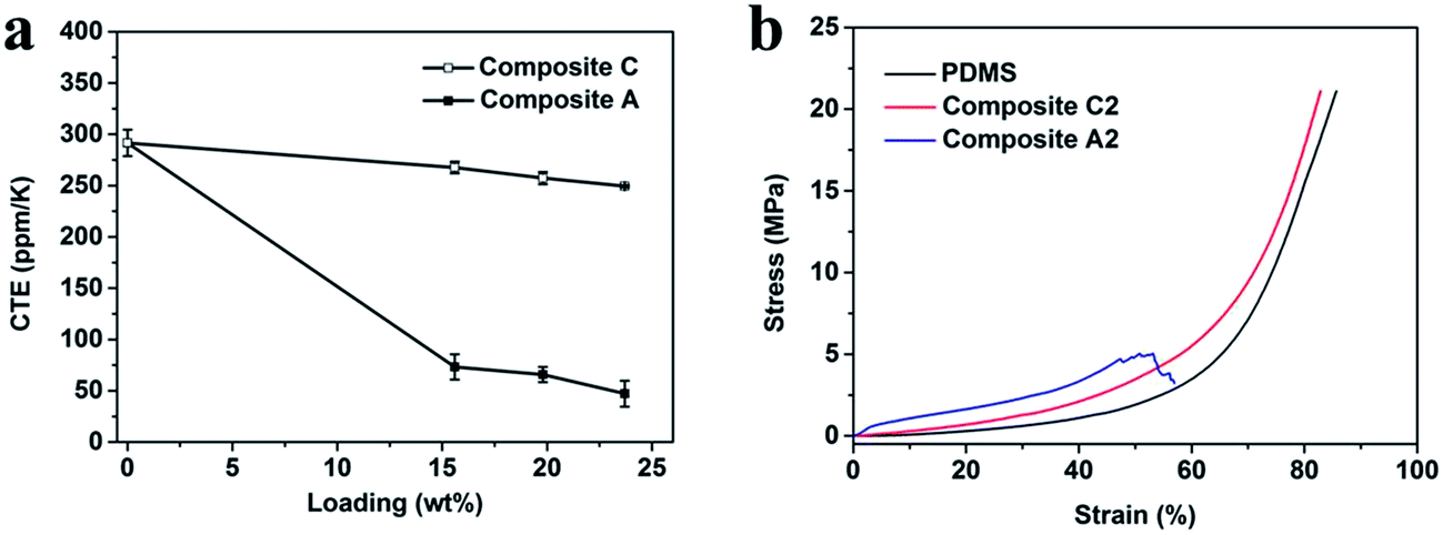 | ||
| Fig. 4 (a) CTEs of Composite A and C along the z direction. (b) Stress–strain curves of PDMS, Composite A2 and Composite C2. | ||
Softness is another important issue for TIMs. The large interface contact thermal resistance due to the air gaps between TIMs and devices will hinder efficient thermal conduction. Therefore, deformation under a small contact pressure is required, to be fully connected with the contact surfaces.8,18 Therefore, PDMS was chosen as the matrix on account of not only its electrical insulation but also its softness. Fig. 4b gives the typical compression curves of PDMS, Composite C2 and Composite A2. The compression behavior of Composite C2 with a random orientation of hBN was similar to PDMS, and they could be compressed to the maximum force of the equipment without any damage. Although Composite A2 has a vertical alignment of hBN microplatelets, it can still be compressed to approximately 50% before cracking. The Young’s modulus of PDMS, and Composite A are listed in Table S2.† The Young’s modulus of Composite A increased with the filler content, and was about one order of magnitude higher than PDMS, but it was still much smaller than epoxy composites, of which the Young’s modulus is as high as several GPa.10
Conclusion
In summary, 3D hBN scaffolds have been successfully prepared by an ice templating method. The scaffolds had a well ordered microstructure with most of the hBN microplatelets aligning vertically. This ordered structure can be maintained in hBN/PDMS composites during the vacuum infiltration process, resulting in a high thermal conductivity of the composites along the z direction. This method is facile, without special surface modification of hBN, and controllable with a high efficiency compared with the previously reported methods. The hBN/PDMS composites also showed a low CTE and softness. This facile strategy for fabrication of TIMs with excellent properties shows potential value in thermal management applications.Acknowledgements
The authors are grateful for Dr Guoliang Dai and Dr Hong Xiao for the help in PCE-TC3 measurement, and thank the Ministry of Science and Technology of China (2014CB643600) and National Natural Science Foundation of China (51173194 and 21421061) for the financial support of this work.References
- A. L. Moore and L. Shi, Mater. Today, 2014, 17, 163–174 CrossRef CAS.
- Y. Zhou, H. Wang, F. Xiang, H. Zhang, K. Yu and L. Chen, Appl. Phys. Lett., 2011, 98, 1–4 Search PubMed.
- X. Huang, T. Iizuka, P. Jiang, Y. Ohki and T. Tanaka, J. Phys. Chem. C, 2012, 116, 13629–13639 CAS.
- J. Cao, X. Zhao, J. Zhao, J. Zha, G. Hu and Z. Dang, ACS Appl. Mater. Interfaces, 2013, 5, 6915–6924 CAS.
- T. Kusunose, T. Yagi, S. H. Firoz and T. Sekino, J. Mater. Chem. A, 2013, 1, 3440–3445 CAS.
- L. Liu, L. Xiao, X. Zhang, M. Li, Y. Chang, L. Shang and Y. Ao, RSC Adv., 2015, 5, 57853–57859 RSC.
- J. S. Park, Y. J. An, W. Shin, J. H. Han and S. Lee, RSC Adv., 2015, 5, 46989–46996 RSC.
- J. Gu, N. Li, L. Tian, Z. Lv and Q. Zhang, RSC Adv., 2015, 5, 36334–36339 RSC.
- X. Huang, P. Jiang and T. Tanaka, IEEE Electr. Insul. Mag., 2011, 27, 8–16 CrossRef.
- Z. Lin, Y. Liu, S. Raghavan, K. S. Moon, S. K. Sitaraman and C. P. Wong, ACS Appl. Mater. Interfaces, 2013, 5, 7633–7640 CAS.
- W.-Y. Zhou, S.-H. Qi, H.-Z. Zhao and N.-L. Liu, Polym. Compos., 2007, 28, 23–28 CrossRef CAS.
- T.-L. Li and S. L.-C. Hsu, J. Appl. Polym. Sci., 2011, 121, 916–922 CrossRef CAS.
- T. L. Li and S. L. C. Hsu, J. Phys. Chem. B, 2010, 114, 6825–6829 CrossRef CAS PubMed.
- M. Donnay, S. Tzavalas and E. Logakis, Compos. Sci. Technol., 2015, 110, 152–158 CrossRef CAS.
- J. Hou, G. Li, N. Yang, L. Qin, M. E. Grami, Q. Zhang, N. Wang and X. Qu, RSC Adv., 2014, 4, 44282–44290 RSC.
- J. Yu, H. Mo and P. Jiang, Polym. Adv. Technol., 2015, 26, 514–520 CrossRef CAS.
- J. Yu, X. Huang, C. Wu, X. Wu, G. Wang and P. Jiang, Polymer, 2012, 53, 471–480 CrossRef CAS.
- K. Wattanakul, H. Manuspiya and N. Yanumet, J. Appl. Polym. Sci., 2011, 119, 3234–3243 CrossRef CAS.
- T. Ji, L.-Q. Zhang, W.-C. Wang, Y. Liu, X.-F. Zhang and Y.-L. Lu, Polym. Compos., 2012, 33, 1473–1481 CrossRef CAS.
- K. Sato, H. Horibe, T. Shirai, Y. Hotta, H. Nakano, H. Nagai, K. Mitsuishi and K. Watari, J. Mater. Chem., 2010, 20, 2749–2752 RSC.
- H. B. Cho, Y. Tokoi, S. Tanaka, H. Suematsu, T. Suzuki, W. Jiang, K. Niihara and T. Nakayama, Compos. Sci. Technol., 2011, 71, 1046–1052 CrossRef CAS.
- W. L. Song, P. Wang, L. Cao, A. Anderson, M. J. Meziani, A. J. Farr and Y. P. Sun, Angew. Chem., Int. Ed., 2012, 51, 6498–6501 CrossRef CAS PubMed.
- H. S. Lim, J. W. Oh, S. Y. Kim, M. J. Yoo, S. D. Park and W. S. Lee, Chem. Mater., 2013, 25, 3315–3319 CrossRef CAS.
- B. H. Xie, X. Huang and G. J. Zhang, Compos. Sci. Technol., 2013, 85, 98–103 CrossRef CAS.
- H. J. Ahn, Y. J. Eoh, S. D. Park and E. S. Kim, Thermochim. Acta, 2014, 590, 138–144 CrossRef CAS.
- H. Shen, J. Guo, H. Wang, N. Zhao and J. Xu, ACS Appl. Mater. Interfaces, 2015, 7, 5701–5708 CAS.
- X. Zeng, L. Ye, S. Yu, H. Li, R. Sun, J. Xu and C. Wong, Nanoscale, 2015, 6774–6781 RSC.
- Z. Kuang, Y. Chen, Y. Lu, L. Liu, S. Hu, S. Wen, Y. Mao and L. Zhang, Small, 2015, 11, 1655–1659 CrossRef CAS PubMed.
- C. Yuan, B. Duan, L. Li, B. Xie, M. Huang and X. Luo, ACS Appl. Mater. Interfaces, 2015, 7, 13000–13006 CAS.
- M. Tanimoto, T. Yamagata, K. Miyata and S. Ando, ACS Appl. Mater. Interfaces, 2013, 5, 4374–4382 CAS.
- C. Yuan, B. Xie, M. Huang, R. Wu and X. Luo, Int. J. Heat Mass Transfer, 2016, 94, 20–28 CrossRef CAS.
- H. B. Cho, T. Nakayama, Y. Tokoi, S. Endo, S. Tanaka, T. Suzuki, W. Jiang, H. Suematsu and K. Niihara, Compos. Sci. Technol., 2010, 70, 1681–1686 CrossRef CAS.
- B. Wicklein, A. Kocjan, G. Salazar-Alvarez, F. Carosio, G. Camino, M. Antonietti and L. Bergström, Nat. Nanotechnol., 2014, 1–7 Search PubMed.
- H. L. Gao, L. Xu, F. Long, Z. Pan, Y. X. Du, Y. Lu, J. Ge and S. H. Yu, Angew. Chem., Int. Ed., 2014, 53, 4561–4566 CrossRef CAS PubMed.
- M. C. Gutiérrez, M. L. Ferrer and F. Del Monte, Chem. Mater., 2008, 20, 634–648 CrossRef.
- M. M. Porter, R. Imperio, M. Wen, M. A. Meyers and J. McKittrick, Adv. Funct. Mater., 2014, 24, 1978–1987 CrossRef CAS.
- E. Munch, M. E. Launery, D. H. Alsem, E. Saiz, A. P. Tomsia and R. O. Ritchie, Science, 2008, 322, 1516–1520 CrossRef CAS PubMed.
- X. Zeng, Y. Yao, Z. Gong, F. Wang, R. Sun, J. Xu and C.-P. Wong, Small, 2015, 11, 6205–6213 CrossRef CAS PubMed.
- C.-W. Nan, R. Birringer, D. R. Clarke and H. Gleiter, J. Appl. Phys., 1997, 81, 6692–6699 CrossRef CAS.
- C. Zhi, Y. Bando, C. Tang, H. Kuwahara and D. Golberg, Adv. Mater., 2009, 21, 2889–2893 CrossRef CAS.
- M. Tanimoto and S. Ando, J. Photopolym. Sci. Technol., 2014, 27, 193–198 CrossRef CAS.
Footnote |
| † Electronic supplementary information (ESI) available. See DOI: 10.1039/c6ra00980h |
| This journal is © The Royal Society of Chemistry 2016 |