
Electrophoretic displays for IR emissivity modulation and temperature control†
Jonathan
Chrun
ab,
Alexandre
Da Silva
 ab,
Cédric
Vancaeyzeele
*a,
Frédéric
Vidal
a,
Pierre-Henri
Aubert
a and
Laurent
Dupont
b
ab,
Cédric
Vancaeyzeele
*a,
Frédéric
Vidal
a,
Pierre-Henri
Aubert
a and
Laurent
Dupont
b
aLaboratoire de Physicochimie des Polymères et des Interfaces (LPPI – EA 2528), I-Mat, CY Cergy Paris Université, 5 mail Gay-Lussac, 95000 Cergy-Pontoise, France. E-mail: cedric.vancaeyzeele@cyu.fr
bOptics Department, Institut Mines-Télécom Atlantique, 29280 Plouzané, France
First published on 22nd November 2022
Abstract
The fabrication of an electrophoretic display operating in the infrared range (MWIR and LWIR) for temperature regulation is described. For this purpose, aluminium-doped zinc oxide (AZO) nanoparticles were the electrophoretic particles of choice. The infrared absorption properties of AZO NPs arise from their localized surface plasmon resonance which results in specific wavelength absorption, depending on the size, shape and aluminium doping ratio. These AZO nanoparticles were then formulated to be incorporated into electrophoretic inks with Isopar L as the solvent. To confer good electrophoretic mobility to AZO, a charge control agent Span 80 was added. Once formulated, these inks were used in an electrophoretic cell that displays a dynamic IR emissivity modulation feature. The cell architecture consists of an electrophoretic ink confined between an asymmetric interdigitated electrode array and an infrared-transparent cover. The final devices present emissivity variations up to Δε 30% in IR-II (MWIR) and Δε 8% in IR-III (LWIR).
Introduction
Thermal regulation has attracted interest in energy saving, which is currently one of the major concerns of society. For military purposes, materials or devices with the ability to regulate their thermal radiations are sought for thermal camouflage applications. In any case, one has to consider that bodies at non-null temperatures give off light or IR radiation.1 The emissivity of a body can be defined as the radiative flux of thermal radiation emitted by a surface element at a given temperature, related to the reference value which is the flux emitted by a black body at this same temperature. In other words, emissivity is a property of a surface which reflects the ability of a material to emit energy. Therefore, the thermal radiation of a body depends on its temperature and emissivity. Thus, there are two main strategies to achieve thermal radiation modulation: one is to change the surface temperature of the body at a constant emissivity, and the other is to tune its surface emissivity at a constant temperature. In this last case, such materials are defined as variable emissivity materials and operate by means of an external stimulus.The use of materials with modulated emissivity in buildings may save energy dedicated to thermal regulation by limiting the excessive use of heaters and air conditioners.2–5 A niche application would be the thermal regulation of spacecrafts.6 In orbit, the spacecraft is subjected to drastic temperature changes, depending on sun or shadow exposures, leading to potential damage to onboard components. Currently the thermal regulation systems of spacecraft display high energy consumption with an associated impact on the onboard mass. Therefore, new materials or devices based on emissivity control to adjust the heat flow, into and out of a building or a spacecraft are being investigated. In a military context, materials or devices with the ability to regulate their thermal radiations are sought to adjust their IR signature with that of their environment and so to reduce the probability to be recognized by means of an IR camera. Indeed, mid-wave infrared (MWIR from 3 to 5 μm) or long-wavelength infrared (LWIR, from 8 to 13 μm) cameras can convert the radiative energy into a pseudo temperature called apparent temperature. Two strategies are currently studied to achieve a dynamic thermal camouflage by adjusting the apparent temperatures of the body in relation to its background environment; either by controlling the surface temperature or by tuning the surface emissivity of the body. The surface temperature can be controlled easily using heat sinks, radiators, Peltier modules as described by BAE Systems with the camouflage system called ADAPTIV.7 However, one of the main drawbacks of this technology is the non-negligible power consumption and/or requirement of a permanent power supply. As a result, to outreach such limitations coatings with variable emissivity have been increasingly studied since the 1990s. Several review articles have reported materials, metamaterials or devices which can dynamically change their emissivity under stimulation.8–10 IR-thermochromic11–13 and IR-electrochromic14–17 materials have been thoroughly investigated. IR-thermochromic materials such as vanadium dioxide (VO2), maintain the same emissivity over a temperature range and for a specific temperature, called the critical temperature (Tc). When the ambient temperature exceeds Tc, the emissivity of these materials changes. IR-electrochromic or electro-emissive materials can modulate their emissivity under the application of a bias voltage. WO3, conductive polymers, lithium titanate, graphene, etc. are the main representatives of electrically IR responsive materials. Humidity and mechanical strain IR responsive materials have also been reported and applied to devices. However, to the best of our knowledge, technologies based on electrophoretic inks, currently used in the visible domain for applications such as e-book readers, have not been applied to devices with variable emissivity.
Electrophoretic display technology is widely used in the visible spectrum of light, nowadays. An electrophoretic pixel is formed by two flat electrodes placed face to face, of which at least one is transparent (e.g. a transparent conductive oxide: ITO, most of the time). The embedded electrophoretic ink is composed of charged pigmented nanoparticles stabilized by a polymeric shell and dispersed in a solvent or a mixture of solvents.18 The principle involved in those displays is based on moving the coloured nanoparticles to show them or not on the front screen of the device and thus obtain a pattern with colour contrast. Under the effect of the electrophoretic force, the positively charged nanoparticles migrate positively from the anode (+) to the cathode (−) and the negatively charged particles will conversely migrate in the opposite direction allowing controlling the display. In an open circuit the particles maintain their position, which confer to the device bistability and so, a low energy consumption.19
To shift towards the infrared part of the electromagnetic spectrum, we considered an electrophoretic ink composed of metal oxide semiconductor-based nanoparticles. They are known to show light or IR absorption because they are able to interfere with incident IR vibration through their localized surface plasmon resonance (LSPR). Under quasi-static conditions, the incident electrical field of light is perceived as being uniform by the nanoparticle itself, which is very small in size when compared to the incident IR wavelength. While under the effect of the incident oscillating electrical field, the electronic cloud of free charge carriers on the nanoparticle starts to oscillate.20,21 The fact that the cloud of free electrons (or holes) is delocalized leads to the formation of a vibrating dipole in the particle's surface, finally leading to IR energy absorption. As a first approximation, the wavelength absorbed and the resulting vibration depends only on the dielectric permittivity of the external medium, and the one of the metal or metal oxide nanoparticle.22–24 Nevertheless, other parameters can shift the maximum wavelength of absorption, such as the size and the shape of the particles.24–26 The properties and use of metallic nanoparticles possessing a plasmonic absorption band in the visible range is well known and widely used for many years, particularly as biosensors,27–29 whereas, metallic oxide nanoparticles possessing a plasmonic band in the infrared range have only recently been studied.30 Among the various oxides reported in the literature, zinc oxides doped with aluminium (AZO) have been thoroughly studied by Della Gaspera et al.30–33 They showed that the nanoparticle plasmonic absorption could encompass the beginning of LWIR with the maximum absorbance at a wavelength close to 8 μm. In addition, research conducted by Peng's group in the early 2000s and based on a solvothermal nanocrystal synthesis route largely provided access to these materials using safer chemicals and low reaction temperatures.34–36 Even if these nanoparticles exhibit a constant IR absorption, they do not show any emissivity modulation without external stimulation and so far, they have not been used as electrophoretic inks to develop dynamic emissivity devices.
In this work, we have designed the first prototype of an electrophoretic display with dynamic IR modulation.37 We used AZO nanoparticles that display IR absorption through their localized surface plasmon resonance (LSPR). The nanoparticle dispersions were then used to formulate an electrophoretic ink, which is the key component of the original prototype of electrophoretic display for IR emissivity modulation. Then, the extent of apparent temperature modulation was characterized as well as the bistability of the device. The original prototype of the electrophoretic display is endowed with dynamic IR emissivity modulation through electrical stimuli. Given the relationship between the IR emissivity modulation and the apparent temperature variation in contrast with the background environment, we tracked its commutation efficiency with IR cameras working in LWIR and MWIR.
Experimental section
Chemicals
Hexadecene (HDE, 92%, Sigma-Aldrich), zinc stearate (Zn(St)2, Acros Organics), aluminium acetylacetonate (Al(acac)3, 99%, TCI Chemicals), 1-dodecanol (98%, Sigma-Aldrich), cyclohexane (99.9%, VWR), ethanol (99.9%, VWR), span 80 (Sigma-Aldrich), Isopar L (VWR) and oleic acid (90%, Sigma-Aldrich) were used without further purification.Instrumentation
X-Ray diffraction spectra were recorded on a XPERT-3 (PANanlytical) with a copper anode (λ = 1.5405980 Å). Electrothermal atomic absorption spectroscopy (ET-AAS) titrations were performed using an atomic absorption spectrometer 200 Series AA (Agilent Technologies) equipped with a graphite tube atomizer GTA 120 and zinc and aluminium hollow cathode lamps (Varian). For scanning transmission electron microscopy (STEM), the nanoparticles were deposited on carbon coated copper TEM grids and imaged using a field emission gun scanning electron microscope (Gemini SEM300, Carl Zeiss, Germany) with an acceleration voltage of 20 keV under a high vacuum. Fourier transform infrared (FTIR) spectroscopy of nanoparticle-based solutions was performed on a Bruker spectrometer (Equinox 55) by averaging 16 consecutive scans with a resolution of 4 cm−1. The liquid cell was composed of two NaCl windows separated by a 100 μm Teflon gasket. Infrared spectroscopy (IR): attenuated total reflection (ATR)-FT-IR spectroscopy was performed on solid dried nanoparticles using a Tensor 27 (Bruker) FT-IR instrument equipped with an ATR accessory unit. The electrophoretic mobility and the hydrodynamic size of nanoparticles were determined by phase analysis light scattering (PALS) and dynamic light scattering (DLS), respectively, using a Nano ZS Malvern Instrument working at λ = 633 nm and backscattering angle θ = 173°. A square-shaped wave electric field from 2.5 to 20 kV m−1 was applied using a dip cell especially designed by Malvern for measurements in non-aqueous environments. Optical microscopy imaging was performed on an Olympus BX60M microscope with an UMPlan FI objective (10×/0.3 BD). The tension generator used is a WaveStation 2012 10 MHz from LeCroy coupled with a Voltage Amplifier A400DI from FLC Electronics and allows the incoming voltage to be multiplied by 20. The band II camera (MWIR) used for thermal imaging is a Thermovision 550 with a spectral range from 3 μm to 5 μm, with a cutting filter of 3.6 μm and a 320 × 256 pixel resolution. It can measure the apparent temperature of objects between −20 °C and 250 °C, with an accuracy of ±2 °C and a sensitivity of less than 0.1 °C. The Band III camera (LWIR) is a FLIR AX5 model with an extended spectral range from 8 μm to 13 μm and a 320 × 256 pixel resolution. It can measure the temperature of objects between −40 °C and 550 °C with an accuracy of ±5 °C and lower sensitivity at 0.05 °C.Synthesis of the nanoparticles
Here, a “one-pot” simple and fast synthesis method is used to prepare the metal oxide nanoparticles, by introducing all the reagents at the same time in a round-bottom flask. Meaning 632 mg of zinc stearate (Zn(St)2), 100 mg of aluminium acetylacetonate (Al(acac)3), 15 mL of hexadecene used as the solvent, 0.95 mL of oleic acid and 4.5 mL of dodecanol. After degassing and inerting (N2) the reaction system, the mixture is firstly heated up to 120 °C for 10 to 20 minutes under vigorous stirring. Then, it is set at 230 °C for 3 hours, while mechanical stirring is maintained. At the end of the reaction, the flask is taken out of the sand bath and left to cool until it reaches room temperature. Ethanol is added to the solution to flocculate the nanoparticles. Then, they are purified three times by precipitation-redispersion in a minimum volume of cyclohexane with a centrifuge (5000 rpm for 20 minutes at 20 °C).Formulation of the electrophoretic ink
The final electrophoretic ink containing doped zinc oxide nanoparticles is prepared with 10 mg mL−1 purified aluminium doped zinc oxide (AZO) nanoparticles dispersed with 0.08 mM SPAN 80 as a charge controller agent in Isopar L.Electrophoretic cell fabrication
The cell fabrication involves etching the electrodes via a photolithography process (Fig. S1, ESI†). Briefly, chrome coated glass substrates are cut to the chosen dimensions (generally in the 2.54 × 2.54 cm format). Then, a thin layer of photoresist S1805 is deposited by spin coating on the conductive layer and then cured at 120 °C. Subsequently, the substrate is exposed to UV light while using an etching mask placed directly on the photoresist film. The whole substrate is placed in a chemical developer to remove the resin exposed under the UV lamp, thus leaving the corresponding conductive layer unprotected. The substrate is then rinsed with water and then placed in an acidic bath to etch the unprotected conductive layer of chromium. Once etched, the substrate is rinsed with deionized water and acetone, revealing the etched electrodes on the glass substrate. Additionally, glue joints are placed on the glass substrate using a digital dispensing robot around the electrodes to create a vat and confine the 10 μL of electrophoretic ink as close as possible to the active areas. This glue joint is then cured under a UV lamp leading to the formation of cavities at around 85 μm (±5 μm) depth. Finally, the electrophoretic cell is sealed by adding a second layer of glue joint on top of the first one with a polyethylene film (80% IR transmission) laminated under vacuum. The whole display unit is then cured under UV to finalize the sealing of the electrophoretic cell.Theoretical background: model for IR emissivity and temperature modulation of the electrophoretic device
Each of the three layers constituting the electrophoretic cell (cover/ink/electrodes) has their own reflectivity R, transmittance t, emissivity ε and temperature T. A schematic representation of the model used for the infrared modelling is presented in Fig. S2 (ESI†). The external environment is modelled with an IR emissive source which can be either hot or cold. This radiation is partly reflected on the surface of the object before being observed by an infrared sensor. The source and the sensor are typically placed under specular conditions, with respect to the surface of the object (the same θ angle). Complementarily, a more complex model derived from the detailed one in the ESI† considers the contributions of the cover, the medium (electrophoretic ink) and the electrodes to better understand the contribution effect of each layer on the infrared properties of the electrophoretic device (Fig. S3, ESI†).38 In order to construct a theoretical model of such a device, the three layers constituting the electrophoretic cell, are considered at the same temperature. The cover and the medium are also considered to be non-reflecting (Rc = Rm = 0), and the transmission coefficient of the electrodes is considered null (te = 0). Each of the three layers constituting the object radiates either directly towards the IR camera, or indirectly, by reflecting IR radiation first on the electrodes before going towards the IR camera (considering cover and ink only). So, it leads to the following equation: Tapp![[thin space (1/6-em)]](https://www.rsc.org/images/entities/char_2009.gif) obj4 = (1 − tc2·tm2·Re)·Tobj4 + tc2·tm2·Re·Tsource4, where Tapp obj is the apparent temperature of the cell, tc corresponds to the IR transmission of the cover, tm the IR transmission of the electrophoretic medium, Re the IR reflectivity of the electrode and Tsource the temperature of the source. The IR transmission terms are squared because the radiation passes through the cover and the medium twice, firstly on the incident path and the second time on the way back after being reflected on the surface of the reflective electrode or the substrate. Thus, the emissivity of the object can be expressed according to the specific parameters of each constituent layer of the cell and therefore becomes: εobj = 1 − tc2·tm2·Re. The as-built electrophoretic device is able to switch from an emissive to a reflective state, while the particles migrate into the ink. To model this migration and this emissivity modulation of the device, the transmission coefficient tm of the medium is defined as a variable. Thus, it can take two extreme values from tem(m) when the particles are uniformly dispersed in the solution to tref(m) when the particles are stacked on the collection electrode. The two corresponding states of the electrophoretic cell (i.e. object) are the emissive and reflective one, respectively. This difference in emissivity between the two states therefore becomes: εem(obj) = 1 − tc2·tem(m)2·Re, where εref(obj) = 1 − tc2·tref(m)2·Re and the variation in emissivity is Δε = Re·tc2·(tref(m)2 − tem(m)2). This equation shows that electrophoretic cells exhibit optimum performance when the electrode reflection coefficient (Re) and the cover transmission coefficient (tc) are maximum (Re = tc = 1). Thus, when the object is in its reflective state, the medium must be as IR-transparent as possible (tref(m) = 1). Conversely, when the object is in its emissive state, the medium must be as IR-opaque as possible and therefore tem(m) = 0.
obj4 = (1 − tc2·tm2·Re)·Tobj4 + tc2·tm2·Re·Tsource4, where Tapp obj is the apparent temperature of the cell, tc corresponds to the IR transmission of the cover, tm the IR transmission of the electrophoretic medium, Re the IR reflectivity of the electrode and Tsource the temperature of the source. The IR transmission terms are squared because the radiation passes through the cover and the medium twice, firstly on the incident path and the second time on the way back after being reflected on the surface of the reflective electrode or the substrate. Thus, the emissivity of the object can be expressed according to the specific parameters of each constituent layer of the cell and therefore becomes: εobj = 1 − tc2·tm2·Re. The as-built electrophoretic device is able to switch from an emissive to a reflective state, while the particles migrate into the ink. To model this migration and this emissivity modulation of the device, the transmission coefficient tm of the medium is defined as a variable. Thus, it can take two extreme values from tem(m) when the particles are uniformly dispersed in the solution to tref(m) when the particles are stacked on the collection electrode. The two corresponding states of the electrophoretic cell (i.e. object) are the emissive and reflective one, respectively. This difference in emissivity between the two states therefore becomes: εem(obj) = 1 − tc2·tem(m)2·Re, where εref(obj) = 1 − tc2·tref(m)2·Re and the variation in emissivity is Δε = Re·tc2·(tref(m)2 − tem(m)2). This equation shows that electrophoretic cells exhibit optimum performance when the electrode reflection coefficient (Re) and the cover transmission coefficient (tc) are maximum (Re = tc = 1). Thus, when the object is in its reflective state, the medium must be as IR-transparent as possible (tref(m) = 1). Conversely, when the object is in its emissive state, the medium must be as IR-opaque as possible and therefore tem(m) = 0.
Results and discussion
Synthesis and characterization of aluminium doped zinc oxide nanoparticles (AZO NP)
The chosen nanoparticles are the aluminium doped zinc oxide nanocrystals (AZO) because of their plasmonic absorption in the wavelength of interest, meaning the LWIR and MWIR regions. The incorporation of aluminium as a dopant in the zinc oxide mesh makes it possible to increase the number of free charge carriers and thus to control the IR absorption bands. Conversely, the pristine zinc oxide (ZnO) nanoparticles show no absorbance in the IR. A colloidal dispersion of nanoparticles can be directly achieved in non-polar solvents through a solvothermal one-pot synthesis pathway.39The alcoholysis reactions of zinc stearate and aluminium acetylacetonate with 1-dodecanol are triggered at 250 °C for 5 h followed by condensation of the formed alcohol that gives rise to the nuclei of aluminium doped zinc oxide nanocrystals (Fig. 1a). The nucleation and growth in hexadecene (HDE) of the AZO crystals is made possible by the addition of oleic acid (OLAC) used as the stabilizing agent. By the end of the synthesis, the nanoparticles are purified by precipitation in a centrifuge with the addition of ethanol, and then finally dispersed and stored for long periods in cyclohexane.
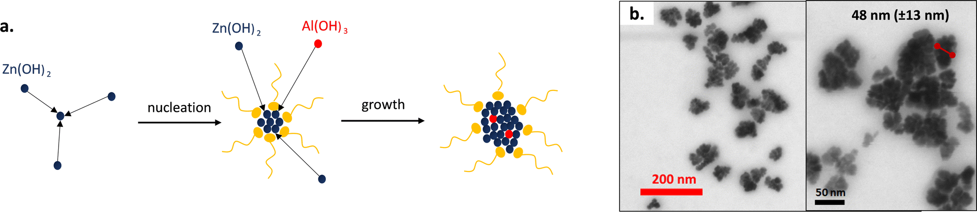 | ||
| Fig. 1 (a) Scheme of aluminium doped zinc oxide nanoparticle formation. (b) STEM images of AZO nanocrystals. | ||
AZO NPs were observed in STEM (Fig. 1b). They exhibit a nanoflower morphology, conversely to the pristine ZnO nanocrystals which show a nanodot shape (Fig. S4, ESI†). We can assume that during the nucleation phase, many nuclei are formed due to the high reactivity of the alcohol initiator and the aluminium precursor. The former nuclei tend to aggregate in order to reduce their surface energy and finally form the nanoflowers. Peng's group has already observed such morphology for indium doped tin oxide nanoparticles.40,41 They have shown that the synthesis of nanocrystals could lead to nanoflowers or nanodots depending on the reactivity of the precursors. The petals are not independent of each other, resulting from crystal aggregations, but are rather linked together by the crystal lattice.
The mean diameter of the AZO nanoflowers was estimated to be around 48.4 ± 12.5 nm. It was confirmed by DLS measurements of AZO dispersed in cyclohexane with a mean diameter of around 51 nm. A polydispersity index PDI of 0.19 was obtained, which corroborates the quite large particle dispersity usually reported for such solvothermal one-pot method.30,42
For a deeper insight, the AZO nanostructures were analysed by XRD spectrometry and compared with the pristine ZnO XRD spectrum shown in Fig. 2a. ZnO XRD diffractogram (black curve) fit with the zincite peaks from an EVA database (attributed peaks), which shows that ZnO nanocrystals do indeed crystallize in the same form as zincite with a crystal lattice of the wurtzite mesh type. The wurtzite is a hexagonal lattice type (unitary lattice) where the zinc atoms are occupying the tetrahedral sites formed by the oxygen atoms and complementarily, the oxygen atoms are placed in the tetrahedral sites formed by the zinc atoms. Because the XRD diffractogram of AZO is perfectly overlaid as well, AZO nanoparticles crystallize in the form of zincite with a wurtzite lattice too. In addition, the nanoparticles containing aluminium did not show new peaks when compared to pristine ZnO. Aluminium therefore does not crystallize independently in the form of aluminium oxide.
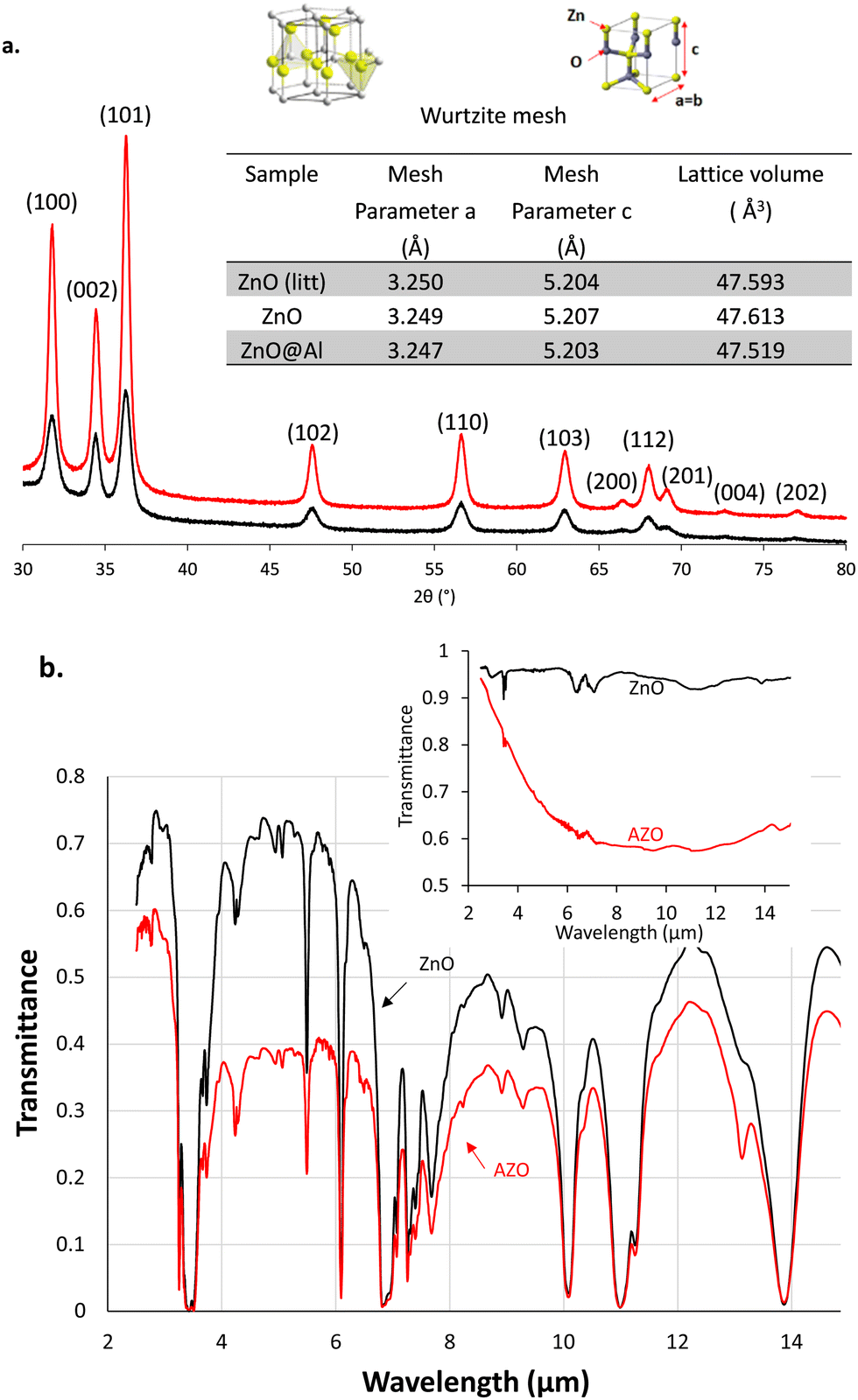 | ||
| Fig. 2 (a) XRD measurement on AZO (in red) and ZnO (in black) nanocrystals. ZnO data from the litterature43 were used as a reference. (b) FT-IR spectrum of 8 mg L−1 of AZO in HDE (red) and pur HDE (black). Inset: the IR-ATR spectrum of dried nanoparticles of AZO (red) and ZnO (black). | ||
The (110) peak was selected to determine the “a” parameter and the (002) peak to determine the “c” parameter from Bragg's formula (2·dhkl·sin(θ) = n·λ). From the lattice parameters the volume of the hexagonal unit cell was then calculated using the formula giving the volume of a cylinder with a hexagonal base V = a2·c·sin(π/3) (inset table in Fig. 2a). The lattice volume was measured equal to 47.613 Å3 for pristine ZnO, consistent with those reported in the literature.43 The lattice volume contracts with the Al doping of nanoparticles. Indeed, AZO has a smaller volume of 47.519 Å3. We can assume that aluminium atoms are then incorporated into the crystal structure of zinc oxide essentially by substituting zinc atoms into the unit cell of wurtzite. The diameter of the zinc atom is larger than that of aluminium, this leads to a volume contraction of the unit cell. As previously observed by Buonsanti et al.,42 the reduction of the lattice parameter did not lead to a shift in diffraction angles from the wurtzite structure to higher values, which could have been expected from a decrease in d-spacings between the atomic planes. XRD also provides information about the crystallite size when evaluating the width at peaks β mid-height and using the Scherrer formula: diameter (nm) = 0.9λ/βcosθ, where λ = 0.1540598 for the copper anode of the apparatus and θ is the angle at the maximum of the peak. Hence, for ZnO, the size of the crystals obtained by XRD is equal to 13.52 ± 1.89 nm, close to the mean size of the nanoparticles observed by electron microscopy 15.9 ± 3.4 nm (Fig. S4, ESI†). However, for AZO nanoparticles, large differences appear in the size of the crystals obtained by XRD reaching about 16.82 ± 1.04 nm and the mean size of the nanoflowers of around 48 nm estimated by STEM. This can be explained by the fact that the crystal size obtained using Scherrer's formula corresponds to the size of the “petals” of the nanoflowers (17.4 ± 3.9 nm by STEM) and not the size of the nanoflowers themselves. The aluminium doping level was obtained by electrothermal atomic absorption spectroscopy using external standard calibration curves for both atoms (Fig. S5, ESI†) and reached 2.3 at% in aluminium when compared to the zinc atom amount. This doping level is far below the aluminium ratio initially added at the beginning of the reaction (25 at%) but remain within the doping ranges reported in the literature for similar reactions (3.5 at% of Al).32
The doping with aluminium metal of zinc oxide nanoparticles confers them a localized surface plasmon resonance in the IR range wavelengths of interest. The dried AZO nanoparticles absorb in the wide IR range while the pristine ZnO exhibited almost no IR absorption as shown in the IR-ATR spectrum (inset in Fig. 2b). Once dispersed in HDE at 8 mg mL−1, AZO absorption overlays with that of the solvent and provides a reduced transmittance below 0.4 with a downwardly shifted baseline in the FT-IR spectrum (Fig. 2b). We took advantage of this particular IR property for the design of an electrophoretic display with IR emissivity modulation.
IR absorbing electrophoretic ink
An electrophoretic ink consists of a colloidal suspension of particles in a non-polar solvent exhibiting a wide electrochemical window. The ink formulation generally consists of halogenated or hydrocarbon-based solvents to which charge control agents and nanoparticles are added. The charge control agent is a dispersing agent, generally a surfactant, added to the ink medium and whose role is to improve the colloidal stability and the electrophoretic mobility of the particles by enhancing their surface charge density and boosting the dielectric properties of the low polar solvent.18,44 Interparticle forces in nonpolar colloids show long-range electrostatic interactions that are tuneable by surface adsorption of neutral, anionic or cationic charge control agents. Typically, the screening lengths in oil are much larger and the charge densities are much lower.45,46 The electrophoretic ink was prepared by dispersing up to 10 mg mL−1 of purified AZO nanoparticles in Isopar L with Span 80 as a charge control agent. SPAN 80 is a commonly used charge control agent for electrophoretic ink.47–50 Given that the free charge carriers on the surface of AZO, responsible for their LSPR, are holes, they make them de facto positively charged. The solvent Isopar L, a mixture of C11 to C15 saturated hydrocarbon chains, was selected due to it is relatively low toxicity and its reduced number of absorption bands in our IR range of interest (Fig. 5a: γC–Hsp3 from 3 to 3.5 μm in MWIR and γC![[double bond, length as m-dash]](https://www.rsc.org/images/entities/char_e001.gif) C and γCC–H at 6.9 and 7.3 μm, respectively, before LWIR). In the proposed electrophoretic set up, the solvent aims to be strictly a dispersion medium for the nanoparticles which are active in the infrared. It is therefore necessary for the solvent to be as transparent as possible in the infrared ranges to optimize the final performance of the device. In addition, Isopar L has a fairly good permittivity of 2.18 for an aliphatic solvent, which promotes good dissociation of charges on the surface of the particles. It also has a low viscosity of 1.55 mm2 s−1 at 40 °C (μHDE = 2.62 mm2 s−1 at 40 °C) allowing better nanoparticle mobility under electric fields. The optimum Span 80 concentration was determined to be equal to 0.08 mM, which gave a ζ potential of 110 mV for an optimal particle's electrophoretic migration (Fig. S7, ESI†). The average particle diameter was increased to around 110 nm (PDI = 0.25), possibly resulting from their solvation or partial flocculation.51
C and γCC–H at 6.9 and 7.3 μm, respectively, before LWIR). In the proposed electrophoretic set up, the solvent aims to be strictly a dispersion medium for the nanoparticles which are active in the infrared. It is therefore necessary for the solvent to be as transparent as possible in the infrared ranges to optimize the final performance of the device. In addition, Isopar L has a fairly good permittivity of 2.18 for an aliphatic solvent, which promotes good dissociation of charges on the surface of the particles. It also has a low viscosity of 1.55 mm2 s−1 at 40 °C (μHDE = 2.62 mm2 s−1 at 40 °C) allowing better nanoparticle mobility under electric fields. The optimum Span 80 concentration was determined to be equal to 0.08 mM, which gave a ζ potential of 110 mV for an optimal particle's electrophoretic migration (Fig. S7, ESI†). The average particle diameter was increased to around 110 nm (PDI = 0.25), possibly resulting from their solvation or partial flocculation.51
Adaptative IR emissive electrophoretic pixel
After carrying out the formulation of IR sensitive electrophoretic inks, the mixture was placed in a home-made electrophoretic cell fabricated under clean room conditions. The architecture of the electrophoretic cell is composed of a covering film, a substrate serving as a support for the electrodes and the formulated IR-absorbing electrophoretic ink (Fig. 3a). This ink is therefore confined between the top cover and the substrate by a glue joint as mentioned earlier. The properties of each of the components must be very specific to obtain the best possible performance in infrared modulation. First, to take advantage of the IR-absorption ability of the particles suspended in the electrophoretic ink to confer the emissive feature to the cell, the cover and the solvent must be as transparent as possible for the IR wavelengths. The working principle of the cell is based on controlling the displacement of the IR-absorbing particles which are embedded in the ink. Thus, the cell can alternate between emissive and reflective states by either placing the particles on the optical path of the IR-reflective background or out of this path. In the cell, the reflective background consists of asymmetrical interdigitated chromium electrodes (Fig. S1, ESI†). One of the electrode digits is wider and used to reflect IR radiation. This first electrode is called the “reflective electrode”. The second thinner interdigitated electrode is used to densely gather the particles on it, namely, the “collection electrode”. To lead to apparent temperature variations via changes in emissivity, this asymmetry seen in Fig. 3b is essential. Optical contrast of the apparent temperature recorded by a thermal camera is generated by masking or uncovering the reflective electrode. The three possible cases are presented in Fig. 3c, one reflective and two emissive states (1&2). In the reflective state, the particles are clustered on the surface of the thinner collection electrode to clear the large surface of the reflective electrode and reveal their reflective behavior. The emissive state 1 corresponds to a state where the particles are homogeneously dispersed in the ink throughout the cell. This therefore masks a large-area of reflective and collection electrodes. The resulting infrared properties of the device will thus approach those of the particles. The emissive state 2 corresponds to a similar state where the particles are stacked on the surface of the reflective electrode. Much like the emissive state 1, the device will have the IR properties of the particles.37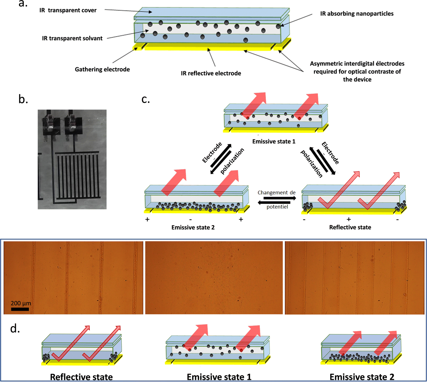 | ||
| Fig. 3 (a) Composition of the electrophoretic cell. (b) Photographs of the in-plan interdigital electrodes with 45% active reflective surface and 110 μm gap between electrodes. (c) Different states allowing to obtain reflective and emissive states with an electrophoretic cell. (Migration of the NPs, related to their zeta potential, and applied potential at the electrodes are arbitrarily selected in the scheme for illustration purposes only.) (d) Schema of the different states of the cell and the corresponding snapshot of the nanoparticles under electrophoretic migration (±200 V at 50 mHz) observed by optical microscopy (Video S1 in the ESI†). | ||
Complementarily, the optical microscopy observations of the operating electrophoretic cell (±200 V at 50 mHz) highlight the three distinct states for the electrophoretic cell (Fig. 3d). The frequency for the electrophoretic cell commutation was set arbitrarily at F = 50 mHz, a low value compared to the time required for the nanoparticles to migrate from one electrode to the other. In the picture on the left, the particles appear clustered on the collection electrode digits, thus uncovering the bigger digits of the reflective electrode and switching the device into the reflective state. This state is obtained when the potential applied to the collection electrode is negative, confirming that the particles are positively charged in the presence of Span 80 in Isopar L according to ζ-potential measurements. While reversing the potential at the electrodes, the emissive state 1 is revealed (middle). The nanoparticles are fully dispersed in the ink while masking the large reflective electrode and the collection electrode areas. Finally, keeping this polarization after some time leads to the emissive state 2 (right) where the nanoparticles are well distributed at the surface of the reflective electrode (brownish colour over the electrode bigger digits). Indeed, the large reflective electrode is covered by absorbing particles, thus setting the system in emissive state 2. During the reversal of potential, agglomerates of particles detach from the collection electrode and break very quickly to allow the particles to spread over the surface of the reflective electrode as shown in Video S1 in the ESI.†
The resulting effect on the apparent temperature of the electrophoretic migration of AZO nanoparticles from the reflective state to emissive state 2 was monitored using a FLIR infrared camera (Fig. 4a and Video S2 in the ESI†). To appropriately measure the emissivity leading to an apparent temperature measurement, the real temperature of the object and the source temperature must be known (see theoretical model in Section 2.6). Thus, the set-up for apparent temperature measurement is composed of the source, i.e. a black body at 65 °C, which is a regulated heat source presenting an emissivity close to 1, an adjustable sample holder and an infrared camera. All this set-up laid in a thermally insulated enclosure for the entire measurement duration.52 The black body and the infrared camera are placed under specular conditions in order to be able to control the apparent temperature reflected at the surface of the sample and thus to determine emissivity variations. While the blackbody is set at 65 °C, the electrophoretic cell remains at room temperature without further temperature modulation. Due to the IR-absorption properties of the nanoparticles and their ability to move from or to the collection electrode, the entire cell will display a higher apparent temperature in the reflective state where the black body is almost entirely reflected to the IR-camera, rather than in the emissive state, where IR-absorbent particles are hiding the reflective electrode.
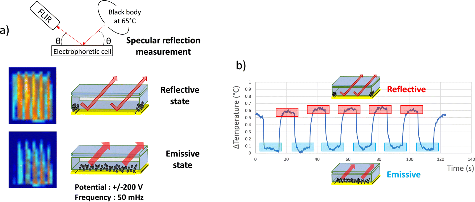 | ||
| Fig. 4 (a) Schema of the set up used to carry out IR camera observations and effect of dynamic emissivity modulation of the electrophoretic cell (in the reflective and emissive state) on the specular reflection of the heat flow of a black body at 65 °C, potential ±200 V and F = 50 mHz (Video S2 in ESI†). (b) Observed temperature modulation of the cell. | ||
The temperature measured with the IR camera was integrated on the surface of the electrophoretic pixel. The mean temperature differences observed in between the two states (see the picture in the inset Fig. 4a) were registered during the electric field application (Fig. 4b). The observed contrast value of 0.6 °C between 31 °C and 31.6 °C on average corresponds to a variation in emissivity of Δε = 1.25% between εref(obj) = 0.754 and εem(obj) = 0.742. Moreover, as shown in the graph, the emissive and reflective states seem repeatedly stable during successive permutations. Thus, the infrared electrophoretic cells seem to present perfectly reversible states. The proof of concept to produce an electrophoretic display dedicated to IR emissivity modulation and temperature control was demonstrated.
Optimization and bistability of the electrophoretic pixel
In order to fabricate an electrophoretic pixel with a large dynamic range of emissivity modulation, two parameters were changed. As previously stated, the emissive state of the device arises from the absorption of the AZO nanoparticles in IR wavelengths through their localized surface plasmon resonance. Then, a simple increase in nanoparticle concentration should result in a more IR-absorbing ink. Fig. 5a compares the transmission spectra of pure Isopar L, the solvent of the ink, an ink formulated with 10 mg mL−1 and another with 40 mg mL−1 AZO. Accordingly, the most concentrated ink has the highest IR absorption. This IR-transmission spectrum therefore shows great potential of more concentrated inks, leading to better contrast in IR-emissivity and thus in apparent temperature control. Similarly, the reflective state has been improved by changing reflective components, i.e. the “reflective electrode”. The former asymmetrical interdigitated electrodes were prepared by etching a 110 μm gap between 200 μm large reflective electrode digits and 20 μm large collection electrode digits. Thus, the reflective electrode corresponded to 45% of the cell surface. A new layout for the interdigitated electrodes has been prepared with 200 μm large strips for the reflective electrode, 20 μm large strips for the collection electrode and a 50 μm gap in between them which lead to 63% of the active reflective surface.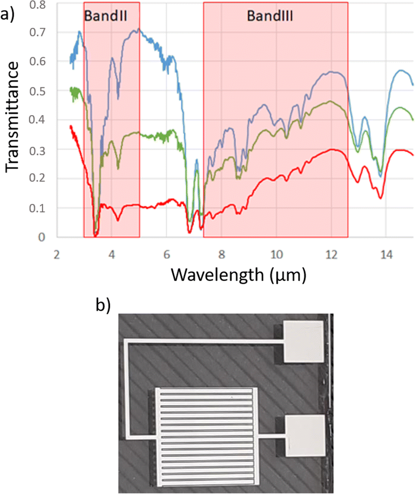 | ||
| Fig. 5 (a) IR spectrum of Isopar L (blue), NP AZO at 10 mg mL−1 (green) and 40 mg mL−1 in Isopar L. (b) Optimized interdigit electrodes with 63% reflective surface and 50 μm gap between electrodes. | ||
The optimized electrophoretic cell, characterized by apparent temperature measurement while being permuted over time in Fig. 6a with a frequency for the commutation set arbitrarily at F = 25 mHz, showing great improvement when compared with the first generation of cells. Indeed, the permutations applied here allowed to reach an apparent temperature contrast of more than 4 °C in LWIR. It corresponds to an emissivity variation of more than Δε 8% between εref(obj) = 0.71 and εem(obj) = 0.79. In addition, the potential differences used to make the particles migrate from one electrode to another are lower than those used in the first generation of cells. The applied field is reduced from 400 Vpp for 110 μm spacing (3.6 V μm−1) to nearly 60 Vpp for 50 μm spacing (1.2 V μm−1) in the last cell architecture presented. This cell presents very interesting characteristics concerning the stability of the states over time. Indeed, over the eight permutations displayed in the graph shown in Fig. 6a, the resulting apparent temperature value for emissive state 2 and the reflective state remained stable at around 31 °C and 35.5 °C, respectively. It can be noticed that there are some irregularities in the waveform curve of the apparent temperature commutation. It comes from random irregularity in the migration of the nanoparticles that partly depends on the history of the electrophetic cell and is the result of some localized but reversible agglomerations of the nanoparticles on the surface of the reflective electrode. The electrical potential modulation needs further improvement to avoid them.
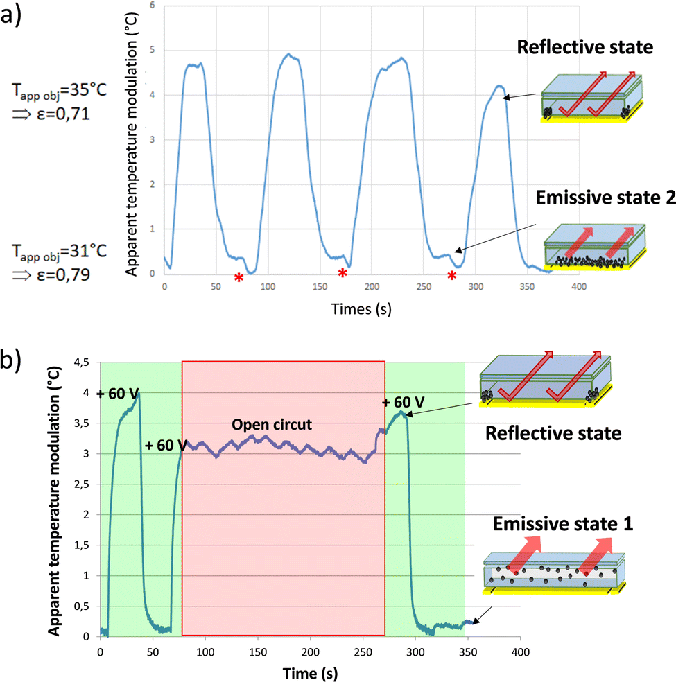 | ||
| Fig. 6 (a) Performance of optimized electrophoretic cell (potential ±30 V and F = 25 mHz). (b) Evaluation of the bistability of the electrophoretic cell (potential +60 V/0 V at F = 25 mHz + open circuit). Apparent temperature observed with an FLIR camera in LWIR. The blackbody is set at 65 °C. | ||
When the cell is in an emissive state, i.e. all the particles are pressed against the reflective electrode and the potential change begins, a slight increase in emissivity is observed (formation of a shoulder just after the plateau, red asterisk in Fig. 6a). During the state transition, the nanoparticles are dispersed throughout the cell, masking the collection electrode in addition to the reflective one. This slight difference represents about 0.4 °C, meaning a bit less than 10% of the total contrast generated. The latter corresponds to the ratio (8%) between the surface occupied by the collection electrode and the total surface of the cell. The aforementioned transitional state generated corresponds here to emissive state 1 with the particles distributed uniformly in the cell.
In Fig. 6b the study considering the bistability of the electrophoretic cell by apparent temperature measurement is presented. So, this emissive state 1 presents better performances in IR absorption than the emissive state 2 with the nanoparticles gathered at the surface of the reflective electrode. Another advantage of keeping particles in suspension in the cell is that they are no longer stacked against the reflective electrode, which might limit the formation of aggregates as well as irreversible adsorption of particles on the electrode surface. It would then benefit in improving ink stability over time.
In Fig. 6b, a typical permutation is displayed with an apparent temperature difference of 4 °C. During the second permutation, the electric field is cut off (red square, open circuit) while the particles are stacked on the collection electrode, thus leaving the device in a reflective state. During this “field off” phase, the oscillations observed are due to the temperature control of the black body kept around 65 °C. This off field was maintained for more than 150 seconds, time during which the cell maintains a relatively stable apparent temperature. Thereafter, the electrical field is reapplied, allowing the cell to return into the emissive state 1. The latter corresponds to the default state of the cell with particles dispersed in the ink and obtained by applying 0 V mean potential. As displayed, the reflective state remained stable over time. The bistability of the device is therefore verified over at least 150 seconds for the reflective state and over much longer durations for the emissive state 1. Power supply is required only during the electrophoretic cell commutation, making it a low energy consumption device.
In order to characterize the performance of the electrophoretic cells also in the MWIR region, the infrared camera of the setup was exchanged with a MWIR (band II) camera with signal acquisition from 3 μm to 5 μm wavelengths. The apparent temperature during the first permutation increased from 32 °C to 46 °C. This difference in apparent temperature of 14 °C corresponds to a variation in emissivity of Δε = 30% between εref(obj) = 0.47 and εem(obj) = 0.77. During the following cycles of commutation, the apparent temperature variations displayed by the device stabilized at around 10 °C between 32 °C and 42 °C, which corresponds to an emissivity variation of Δε = 21% between εref(obj) = 0.56 and εem(obj) = 0.77. This slight initial decrease in contrast performance might be attributed to slight nanoparticle aggregation on the reflective electrode over time.
Conclusion
The synthesis of aluminium-doped zinc oxide (AZO) nanoparticles was studied to develop a reproducible and easy-to-implement process resulting in nanoparticles sufficiently doped to obtain the desired LSPR absorption properties, i.e. in the MWIR and LWIR wavelengths. The so-called “one-pot” solvothermal method was chosen. Briefly the zinc and aluminium precursors, alcohol initiator and stabilizing agent were dissolved and heated-up in a low polarity hydrocarbon solvent. The obtained AZO nanoparticles were doped with 2.3 at% of Al. They are nanoflowers with about 50 nm average diameter exhibiting 17 nm crystal petals and structured in a wurtzite-type mesh, typical of zincite. These IR absorbing AZO nanoparticles were then wisely used as the IR sensitive component of electrophoretic inks which are also composed of a charge control agent (Span 80) dispersed in Isopar L. Finally, this ink was placed in the home-made electrophoretic cell designed to display IR emissivity modulation and to achieve temperature control. The architecture of the electrophoretic cell is composed of a covering layer, a substrate serving as a support for the in plane interdigitated electrodes and the formulated infrared absorbing electrophoretic ink. Optical and IR contrast are achieved by masking or uncovering the reflective electrode with AZO nanoparticles by means of an electrophoretic migration, perfectly controlled by applying a potential difference at the electrodes. The apparent temperature variations on the cell were observed through an IR-camera by variation in emissivity detection. The first generation of electrophoretic cells made it possible to obtain a proof of concept, exhibiting performances in variation of emissivity, which were certainly modest, but sufficient to be observed with a commercial IR-camera, at around Δε = 1.25% in IR-III/LWIR. The display optimizations achieved with AZO nanoparticle concentration and surface of the reflective electrode increase have significantly improved its performances, thus showing an emissivity modulation reaching more than Δε = 30% between εref(obj) = 0.47 and εem(obj) = 0.77 in IR-II/MWIR and up to Δε = 8% between εref(obj) = 0.71 and εem(obj) = 0.79 in IR-III/LWIR. The electrophoretic display presented here stands as a good candidate for light weight and low energy consuming radiator fabrication, allowing us to consider further useful applications such as spacecraft efficient thermal control and much more.Conflicts of interest
There are no conflicts to declare.Acknowledgements
The authors thank DGA (Délégation Générale pour l’Armement) for funding support (PhD funding no. 2017512 and 2020505). We also would like to thank the Conseil regional île de France for the cofunding the ZEISS Gemini SEM 300 (Cerasem project - grant number 15013107).References
- T. Kogure and K.-C. Leung, The Astrophysics of Emission-Line Stars, Springer New York, New York, NY, 2007, vol. 342 Search PubMed.
- R. D. Rauh, Electrochim. Acta, 1999, 44, 3165–3176 CrossRef CAS.
- D. R. Rosseinsky and R. J. Mortimer, Adv. Mater., 2001, 13, 783–793 CrossRef CAS.
- J. C. Gustafsson-Carlberg, O. Inganäs, M. R. Andersson, C. Booth, A. Azens and C. G. Granqvist, Electrochim. Acta, 1995, 40, 2233–2235 CrossRef CAS.
- R. J. Mortimer, Electrochim. Acta, 1999, 44, 2971–2981 CrossRef CAS.
- F. Vidal, G. Petroffe, L. Beouch, S. Cantin, C. Chevrot, P.-H. Aubert and J.-P. Dudon, Smart Materials, Springer International Publishing, Cham, 2022, pp. 221–254 Search PubMed.
- O. Thorén, BAE Systems – ADAPTIV, https://www.baesystems.com/en/feature/adativ-cloak-of-invisibility, accessed Nov 2022.
- Z. Li and W. Chen, Mater. Chem. Front., 2021, 5, 6315–6332 RSC.
- J. Niu, Y. Wang, X. Zou, Y. Tan, C. Jia, X. Weng and L. Deng, Appl. Mater. Today, 2021, 24, 101073 CrossRef.
- R. Hu, W. Xi, Y. Liu, K. Tang, J. Song, X. Luo, J. Wu and C.-W. Qiu, Mater. Today, 2021, 45, 120–141 CrossRef CAS.
- C. G. Granqvist, Sol. Energy Mater. Sol. Cells, 2007, 91, 1529–1598 CrossRef CAS.
- K. L. Lewis, A. M. Pitt, T. Wyatt-Davies and J. R. Milward, MRS Proc., 1994, 374, 105 CrossRef.
- F. Yu-Dong, W. Zhi-Min, M. Ya-Li and Z. Fu-Jia, Chin. Phys., 2007, 16, 1704–1709 CrossRef.
- T. D. Swanson and G. C. Birur, Appl. Therm. Eng., 2003, 23, 1055–1065 CrossRef.
- D. M. Douglas, T. Swanson, R. Osiander, J. Champion, A. G. Darrin, W. Biter and P. Chandrasekhar, AIP Conference Proceedings, AIP, 2002, vol. 608, pp. 204–210.
- E. B. Franke, C. L. Trimble, J. S. Hale, M. Schubert and J. A. Woollam, J. Appl. Phys., 2000, 88, 5777–5784 CrossRef CAS.
- P. Chandrasekhar, B. J. Zay, D. Lawrence, E. Caldwell, R. Sheth, R. Stephan and J. Cornwell, J. Appl. Polym. Sci., 2014, 131, 40850 Search PubMed.
- I. Ota, J. Ohnishi and M. Yoshiyama, Proc. IEEE, 1973, 61, 832–836 CAS.
- M. Goulding, N. Smith, L. Farrand, C. Topping, S. Norman, A. Sauter, G. Cooper, H. S. Jin and J. Y. Lee, Soc. Inf. Disp. Symp. Dig. Tech. Pap., 2015, 46, 326–329 CrossRef CAS.
- G. V. Hartland, Chem. Rev., 2011, 111, 3858–3887 CrossRef CAS.
- S. Nath, S. Jana, M. Pradhan and T. Pal, J. Colloid Interface Sci., 2010, 341, 333–352 CrossRef CAS PubMed.
- G. Mie, Ann. Phys., 1908, 330, 377–445 CrossRef.
- T. R. Jensen, M. L. Duval, K. L. Kelly, A. A. Lazarides, G. C. Schatz and R. P. Van Duyne, J. Phys. Chem. B, 1999, 103, 9846–9853 CrossRef CAS.
- X. Fan, W. Zheng and D. J. Singh, Light: Sci. Appl., 2014, 3, 179–186 CrossRef.
- K. L. Kelly, E. Coronado, L. L. Zhao and G. C. Schatz, J. Phys. Chem. B, 2003, 107, 668–677 CrossRef CAS.
- M. Rycenga, C. M. Cobley, J. Zeng, W. Li, C. H. Moran, Q. Zhang, D. Qin and Y. Xia, Chem. Rev., 2011, 111, 3669–3712 CrossRef CAS PubMed.
- A. J. Haes and R. P. Van Duyne, Anal. Bioanal. Chem., 2004, 379, 920–930 CrossRef CAS PubMed.
- E. Hutter and J. H. Fendler, Adv. Mater., 2004, 16, 1685–1706 CrossRef CAS.
- K. A. Willets and R. P. Van Duyne, Annu. Rev. Phys. Chem., 2007, 58, 267–297 CrossRef CAS PubMed.
- S. D. Lounis, E. L. Runnerstrom, A. Llordés and D. J. Milliron, J. Phys. Chem. Lett., 2014, 5, 1564–1574 CrossRef CAS PubMed.
- E. Hammarberg, A. Prodi-Schwab and C. Feldmann, J. Colloid Interface Sci., 2009, 334, 29–36 CrossRef CAS.
- E. Della Gaspera, A. S. R. Chesman, J. Van Embden and J. J. Jasieniak, ACS Nano, 2014, 8, 9154–9163 CrossRef CAS.
- S. D. Lounis, E. L. Runnerstrom, A. Bergerud, D. Nordlund and D. J. Milliron, J. Am. Chem. Soc., 2014, 136, 7110–7116 CrossRef CAS.
- L. Qu, Z. A. Peng and X. Peng, Nano Lett., 2001, 1, 333–337 CrossRef CAS.
- Z. A. Peng and X. Peng, J. Am. Chem. Soc., 2002, 124, 3343–3353 CrossRef CAS.
- J. J. Li, Y. A. Wang, W. Guo, J. C. Keay, T. D. Mishima, M. B. Johnson and X. Peng, J. Am. Chem. Soc., 2003, 125, 12567–12575 CrossRef CAS.
- J. Chrun, L. Dupont, F. Vidal, P.-H. Aubert, C. Vancaeyzeele, E. Petitpas, S. Fagour and S. Legall, Infradred Reflectivity Control Device, WO2021205280, 2021 Search PubMed.
- J. Chrun, Doctoral dissertation, Ecole nationale supérieure Mines-Télécom Atlantique Bretagne Pays de la Loire, 2021.
- L. Cademartiri and G. A. Ozin, Philos. Trans. R. Soc., A, 2010, 368, 4229–4248 CrossRef CAS.
- A. Narayanaswamy, H. Xu, N. Pradhan, M. Kim and X. Peng, J. Am. Chem. Soc., 2006, 128, 10310–10319 CrossRef CAS.
- A. Narayanaswamy, H. Xu, N. Pradhan and X. Peng, Angew. Chem., Int. Ed., 2006, 45, 5361–5364 CrossRef CAS.
- R. Buonsanti, A. Llordes, S. Aloni, B. A. Helms and D. J. Milliron, Nano Lett., 2011, 11, 4706–4710 CrossRef CAS PubMed.
- C. F. Klingshirn, B. K. Meyer, A. Waag, A. Hoffmann and J. Geurts, Zinc Oxide, Springer Berlin Heidelberg, Berlin, Heidelberg, 2010, vol. 120 Search PubMed.
- B. J. Park, S. Y. Hong, H. H. Sim, H. J. Choi and Y. S. Yoon, Mater. Chem. Phys., 2012, 135, 259–263 CrossRef CAS.
- S. K. Sainis, V. Germain, C. O. Mejean and E. R. Dufresne, Langmuir, 2008, 24, 1160–1164 CrossRef CAS PubMed.
- M. E. Parent, J. Yang, Y. Jeon, M. F. Toney, Z. L. Zhou and D. Henze, Langmuir, 2011, 27, 11845–11851 CrossRef CAS PubMed.
- M. J. Joung, C. A. Kim, S. D. Ahn, Y. E. Lee, S. Y. Kang, K. S. Suh and C. H. Kim, MRS Proc., 2003, 769, H6.20 CrossRef.
- X.-N. Yao, J.-P. Wang, X.-X. Zhang and X.-C. Wang, in Second International Conference on Smart Materials and Nanotechnology in Engineering, ed. J. Leng, A. K. Asundi and W. Ecke, 2009, vol. 7493, p. 749352.
- C. A. Kim, S.-Y. Kang, G. H. Kim, S. D. Ahn, J. Oh and K. S. Suh, Mol. Cryst. Liq. Cryst., 2009, 499, 282–289 Search PubMed.
- A. Noël, D. Mirbel, A. Charbonnier, E. Cloutet, G. Hadziioannou and C. Brochon, J. Polym. Sci., Part A: Polym. Chem., 2017, 55, 338–348 CrossRef.
- E. L. Michor and J. C. Berg, Langmuir, 2015, 31, 9602–9607 CrossRef CAS PubMed.
- S. Le Gall, Doctoral dissertation, Ecole nationale supérieure Mines-Télécom Atlantique Bretagne Pays de la Loire, 2018.
Footnote |
| † Electronic supplementary information (ESI) available. See DOI: https://doi.org/10.1039/d2tc04147b |
| This journal is © The Royal Society of Chemistry 2023 |