 Open Access Article
Mono-, bi- and tri-metallic platinum group metal-free electrocatalysts for hydrogen evolution reaction following a facile synthetic route†
Seyed Ariana
Mirshokraee
a,
Mohsin
Muhyuddin
a,
Jacopo
Orsilli
a,
Enrico
Berretti
 b,
Laura
Capozzoli
b,
Alessandro
Lavacchi
b,
Carmelo
Lo Vecchio
b,
Laura
Capozzoli
b,
Alessandro
Lavacchi
b,
Carmelo
Lo Vecchio
 c,
Vincenzo
Baglio
c,
Anna
Galli
a,
Andrea
Zaffora
c,
Vincenzo
Baglio
c,
Anna
Galli
a,
Andrea
Zaffora
 d,
Francesco
Di Franco
d,
Monica
Santamaria
d,
Francesco
Di Franco
d,
Monica
Santamaria
 d,
Luca
Olivi
 e,
Simone
Pollastri
 ef and
Carlo
Santoro
 *a
*a
aDepartment of Materials Science, University of Milano-Bicocca, U5, Via Cozzi 55, 20125, Milano, Italy. E-mail: carlo.santoro@unimib.it
bIstituto di Chimica Dei Composti OrganoMetallici (ICCOM), Consiglio Nazionale Delle Ricerche (CNR), Via Madonna Del Piano 10, 50019 Sesto Fiorentino, Firenze, Italy
cIstituto di Tecnologie Avanzate per l'Energia “Nicola Giordano” (ITAE), Consiglio Nazionale delle Ricerche (CNR), Via Salita S. Lucia sopra Contesse 5, Messina, 98126, Italy
dDepartment of Engineering, University of Palermo, Viale delle Scienze, 90128, Palermo, Italy
eArea Science Park, Elettra-Sincrotrone Trieste, Basovizza, Trieste, Italy
fDepartment of Physics, Computer Science and Mathematics, University of Modena and Reggio Emilia, Via Campi 103, 41125 Modena, Italy
First published on 20th July 2023
Abstract
In this work, platinum group metal-free (PGM-free) electrocatalysts were synthesized, characterized, and tested for hydrogen evolution reaction (HER). These materials were mono-, bi- and trimetallic Ni-based electrocatalysts with the addition of a second or a third transition metal (TM), such as iron and cobalt. TM–phthalocyanine (TMPc) was used as a metal precursor, mixed with a conductive carbon backbone and subjected to pyrolysis under controlled temperature and atmosphere conditions. Two temperatures of pyrolysis (600 °C and 900 °C) were used. The effect of TM loading in the precursors, different pyrolysis temperatures on the surface chemistry and morphology, and electrocatalytic activity towards HER were evaluated. The increase of NiPc in the initial mixture is beneficial to improving the electrocatalytic activity. The addition of a second and a third metal reflects positively on the HER performance. Interestingly, the pyrolysis temperature influences both the formation and growth of the nanoparticles, and this information is supported by high-resolution transmission electron microscopy (HR-TEM) and light synchrotron X-ray absorption spectroscopy (XAS) measurements.
Keywords: Hydrogen evolution reaction; PGM-free electrocatalyst; Hydrogen production; Ni-based electrocatalyst.
1 Introduction
Hydrogen with clear-sighted solutions to climate challenges is emerging as a modern energy vector. Owing to its higher power, greater energy density, and negligible contribution to carbon footprint, hydrogen can be regarded as a rational and sustainable fuel. The clean production of hydrogen through water electrolysis can be coupled with renewable energy resources, i.e., wind and solar, that would otherwise lose their practicality due to weather dependency and intermittent disruption. Hence, hydrogen can potentially fuel the automobile, domestic and industrial sectors with zero emissions.1–3Presently, low-temperature water electrolyzers have three main classes.3 The first category, named alkaline water electrolyzers (AWEs), is technologically mature and commercially available. In AWEs, the anode and cathode are immersed into an electrolyte solution containing about 6 M KOH, and the two compartments are divided by a porous diaphragm. This separation does not allow for pressurizing the hydrogen formed. The two electrodes need to be separated, increasing the ohmic resistance of the system and lowering the performance. AWEs, in fact, produce hydrogen at low current density in the order of 0.5 A cm−2.4–6 On the other hand, the second type is represented by proton exchange membrane water electrolyzers (PEMWEs). The electrodes in PEMWEs are separated by a polymeric proton exchange membrane, allowing the electrochemical pressurization of the hydrogen within the system itself. PEMWEs have the highest performance and are able to reach up to 5 A cm−2.7 However, the main drawback is the extensive usage of platinum group metal (PGM) and critical raw materials (CRMs) in their components. The last and the least established technology consists of anion exchange membrane water electrolyzers (AEMWEs). AEMWEs may be promising as they synergistically combine the advantages of both AWEs and PEMWEs; they are capable of working without relying on CRMs and supplementary hydrogen pressurizing systems, and provide high current density (>1 A cm−2). The mass-scale deployment of water electrolyzers is limited by the higher cost and scarcity of PGMs and CRMs. Therefore, AEMWEs could be an ideal option if the performance can be improved.8 In order to fulfill the potential high request from the market in terms of hydrogen production at a low cost, alkaline technologies (both AWE and AEMWE) need to be used. This selection takes the advantage of avoiding PGMs and CRMs, which will lower the cost and make the systems affordable.
In alkaline systems (AWE and AEMWE), the slow kinetics and high overpotentials of the hydrogen evolution reaction (HER) and oxygen evolution reaction (OER) at the cathode and anode, respectively, are major technological constraints that prevent the widespread application of water electrolysis.9,10 A plethora of efforts has been devoted to improve the performance of the anode and cathode electrocatalysts, while not using PGMs and CRMs. Focusing on HER in an acidic environment, the best HER electrocatalyst performance is achieved by platinum supported over carbon (Pt/C). However, Pt belongs to the overpriced and scarce PGM electrocatalysts, which are considered CRMs by the EU.11 Often, this solution is also translated into alkaline environments. In an alkaline environment, it is possible to operate without PGMs. Therefore, the replacement of PGMs with efficient and nonprecious PGM-free electrocatalysts is the main focus of current research on HER and water electrocatalysis.12
One promising approach is to employ transition metals (TMs), such as Fe, Co, and Ni, which are embedded in a carbon matrix, in the form of atomically dispersed TM or nanoparticles that can form alloys (in the case of more than one TM) when subjected to high-temperature processes.12–16 Under less corrosive alkaline conditions, these materials display reasonable kinetic activity.17,18 In addition, the defect-rich structure of carbon ensures a catalytically conductive platform.19,20 Among the existing TMs, Ni-based electrocatalysts have shown promising electrocatalytic activity toward the evolution of hydrogen.21 Belonging to the 10th group of the periodic table, Ni shares many similar electronic properties with Pd and Pt, both of which are excellent electrocatalysts for HER. In Ni-based electrocatalysts, the Ni nanoparticles and atomically dispersed Ni play an important role in improving the HER electrocatalysis.22–24 Thus, the HER activity of different Ni morphologies (such as film, particle, dendrite, etc.) was investigated by Ahn et al., and it was shown that dendrites with highly populated (111) facets at the sharp edge and downshift d-band center showed the best performance.25 In another investigation, a hybrid Ni/NiO/CoSe2 with a lower charge transfer was developed.26 However, similar to the 3D ordered macro-/mesoporous Ni,27 one drawback of Ni/NiO/CoSe2 was that the urchin-like Ni NPs showed poor stability and/or suffered from insufficient electrocatalytic activity.28 To overcome this problem, the synthesis of the single-atom Ni doped on nanoporous graphene was reported.29 This electrocatalyst has much higher stability and a lower overpotential. In related works, the Ni–Fe alloy and Ni–Cu (bi-metallic) NPs encapsulated with an N-doped graphitized carbon shell (NiFe@NC) were developed, showing excellent HER activity and stability.30,31 The tri-metallic alloy, Fe–Co–Ni, was synthesized and analyzed by Hao et al.32 According to the DFT calculation results, the choice of TMs are important and their ratio affects the HER performance.33 TM-based trimetallic alloys are promising electrocatalysts owing to their cost effectiveness and their electrocatalytic activity. However, more studies need to be done in order to understand how the different metals give synergistic outcomes.34–36
This work presents a strategy to improve the HER electrocatalysis in an alkaline medium by enhancing the electrocatalytic activity of Ni-based electrocatalysts through mono-, bi-, and trimetallic incorporations and alloying starting from simple and low-cost molecular catalysts, such as TM phthalocyanine (TM–Pc). The experimental design targets two underlying aims: (a) to elucidate the influence of different functionalization temperatures on the HER activity of monometallic electrocatalysts with different Ni phthalocyanine (NiPc) weight percentages (wt%), and (b) to identify the effect of the addition of a second and third TM in the Ni-based electrocatalyst in a bimetallic and trimetallic fashion subjected to different functionalization temperatures on the HER activity.
The fabrication of the electrocatalysts involved mixing commercially available electro-conductive Ketjen-black carbon (KJB) with different TM–Pc by ball-miller, and then functionalizing at two different temperatures of 600 °C and 900 °C via atmosphere-controlled pyrolysis (1 h in an inert atmosphere (ultra-high pure Ar flux)). Firstly, the electrocatalysts based on KJB and NiPc were mixed in different wt% of the NiPc (30, 20, 15, and 10 wt%). Their performance was then recorded and compared to identify the influence of the Ni content on the HER activity. The next step of this study was related to the examination of the effects of a different component (mono, bi and trimetallic), with an overall 30 wt% of TMs-Pc component used to synthesize the Ni-based electrocatalyst samples. A mono-metallic Ni-based electrocatalyst (30 wt% of NiPc), bi-metallic Ni–Co electrocatalyst (15 wt% of NiPc and 15 wt% of CoPc), and tri-metallic Ni–Fe–Co electrocatalyst (10 wt% of NiPc, FePc, and CoPc respectively) were synthesized, and their performances were compared in alkaline medium. The effects of synthesis conditions such as functionalization temperatures on the overall electrochemical performance in the alkaline conditions were closely analyzed for every sample group. The outcomes of the given research work contribute to the development of efficient electrocatalysts for HER to replace PGM-based electrocatalysts.
2 Results and discussion
2.1 Morphological investigation
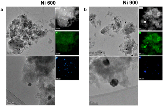
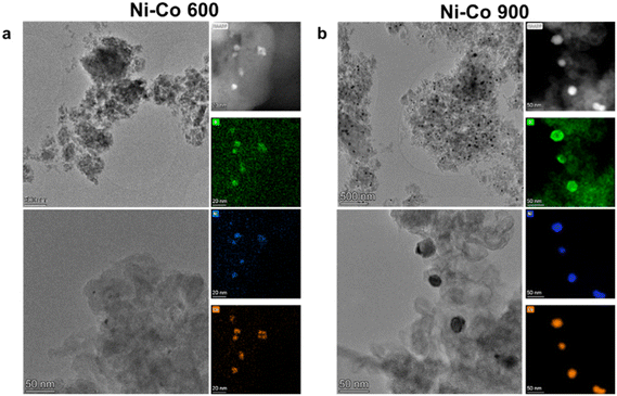
The physicochemical characterizations of the as-developed electrocatalysts began through morphological and compositional investigations using multiple spectroscopic and microscopic techniques, such as high-resolution transmission electron microscopy (HRTEM), scanning transmission electron microscopy (STEM), and energy dispersive X-ray spectroscopy (EDX). From the characterization, some degree of nanoparticle formation was visible for all of the sample series (mono-, bi- and tri-metallic), both for 600 °C to 900 °C, with an important dimensional increase for the higher temperatures. Starting from the mono-metallic Ni samples, the comparison of the two process temperatures is shown in Fig. 1, where an increase of the dimension of the nanoparticles can be observed as the temperature increases, together with a change of shape. In Ni 600, the nanoparticles tend to have a cubic shape, with an average side dimension of 26 nm. Meanwhile, the nanoparticles modify their shape to spherical in Ni 900, with an average diameter of about 45 nm. This change is almost doubled with respect to the 600 °C ones. Regarding the compositional maps obtained by EDX by comparing the Ni and the O maps, a superimposition of the signal from the two elements can be observed in Ni 900. This observation reveals that the Ni nanoparticles in the former sample are mainly in the form of oxides. This is much more difficult for sample Ni 600, where no strong oxide signal can be correlated to the Ni presence in the nanoparticles, suggesting a very thin oxide layer on the surface.The characterization results over Ni–Co 600 and Ni–Co 900 are reported in Fig. 2. From the HRTEM images, although spherical nanoparticles can be found in both electrocatalyst structures, there are more nanoparticles with larger sizes in Ni–Co 900 (average diameter 36 nm) compared to Ni–Co 600 (average diameter 5 nm). The HAADF results confirm this observation. Regarding the EDX results, it is possible to see that the visible particles in both samples are made of both Ni and Co, with an average atomic ratio of 1![[thin space (1/6-em)]](https://www.rsc.org/images/entities/char_2009.gif) :
:![[thin space (1/6-em)]](https://www.rsc.org/images/entities/char_2009.gif) 2, and that they are mainly made by oxides. The presence of a strong background signal for nickel and cobalt in the 600 °C sample also suggests an incomplete conversion of the two elements in the nanoparticles.
2, and that they are mainly made by oxides. The presence of a strong background signal for nickel and cobalt in the 600 °C sample also suggests an incomplete conversion of the two elements in the nanoparticles.
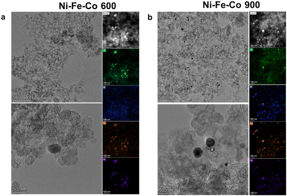
Regarding the comparison between the Ni–Fe–Co 600 and Ni–Fe–Co 900 (tri metallic) electrocatalysts in Fig. 3, HRTEM and HAADF demonstrate the existence of nanoparticles in the electrocatalyst structures for both temperature ranges. Qualitatively speaking, it is interesting to notice how the particles tend to maintain a smaller dimensional dispersion for the 600 °C sample (about 28 nm diameter), while an increase in the number of nanoparticles and a bigger dimensional spread (from 15 to 60 nm) can be seen in the 900 °C sample. Moreover, according to the EDX acquisitions, nanoparticles in Ni–Fe–Co 600 were composed mainly of Fe oxides (>90% at) with Ni as a lesser element (<2% at). Meanwhile, for the Ni–Fe–Co 900, the ratio between the elements seems to change, with an increase in the Co (approx. 50% at) and an intermediate amount of Fe (approx. 30% wt).
2.2 Raman analysis
In Fig. 4, the Raman spectra of the Ni-based electrocatalysts are shown. The Raman spectra were mainly composed of typical carbon signatures, where the G band located at ∼1580 cm−1 is attributed to the E2g2 vibration mode of sp2 bonded carbon atoms in graphite with D6h4 crystal symmetry, while the D band or the defect band emerges at ∼1350 cm−1 due to in-plane defects and heteroatoms and imperfections in sp2 carbon structures.37–39 Two other peaks can also be recognized, especially in the spectra related to the functionalized electrocatalyst at 600 °C. The first one is the D2 band (D*), which appears at ∼1620 cm−1 as a shoulder on the G band.40 The discontinuity defects offer the lost momentum needed to satisfy the resonant process in intravalley double resonance scattering, and it causes the emergence of the D* band.41–44 This defect-induced Raman feature usually shows up in very poorly organized carbon structures, and is absent in highly crystalline structures.41,45–48 Another peak occurs only in poor crystallized carbon at ∼1500 cm−1 and is called the D3 band. Defects outside the plane of aromatic layers, such as tetrahedral carbons, are the reasons for the existence of D3 band.38,40 The integrated intensity ratio ID/IG for the D band and G band is used as quantitative parameters of the graphitization process and for characterizing the defect quantity in graphitic materials. Graphitization plays an important role the electron transfer during electrocatalysis. Besides graphitization, defects and discontinuities within the carbonaceous structure are considered electrocatalytically active moieties for HER.49,50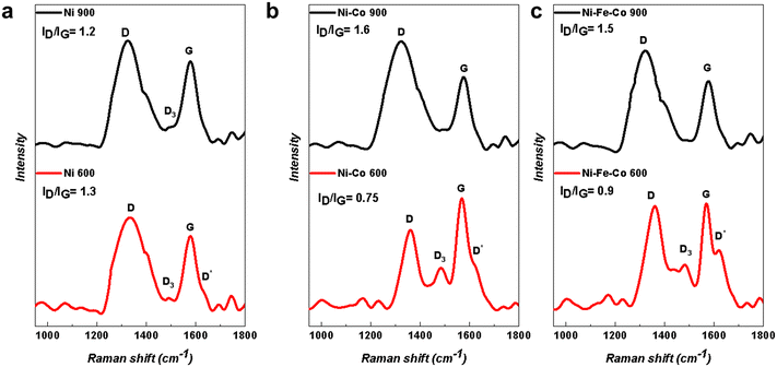 | ||
| Fig. 4 Raman spectra of the Ni-based electrocatalysts with two different functionalization temperatures of 600 °C and 900 °C for the (a) Ni; (b) Ni–Co; and (c) Ni–Fe–Co samples. | ||
According to the Raman spectra in Fig. 4, the electrocatalysts with a functionalization temperature of 900 °C had a higher degree of graphitization compared to the samples with a functionalized temperature of 600 °C. In fact, by increasing the functionalization temperature, the intensity ratio ID/IG was changed. In the case of the mono-atomic Ni-based electrocatalyst samples (Ni 600 and Ni 900) (Fig. 4a), the ID/IG ratio decreased. However, in the case of bi-metallic (Ni–Co 600 and Ni–Co 900) and tri-metallic (Ni–Fe–Co 600 and Ni–Fe–Co 900) (Fig. 4b and c), the situation is the opposite and an increase in the ID/IG ratio can be observed.
2.3 X-ray diffraction results and interpretation
XRD was used to study the crystallographic features of the as-developed electrocatalysts, as shown in Fig. 5. Two broad peaks centering at ca. 24° (002) and 44° (101) that belong to the amorphous carbon are visible.51 These peaks came from the backbone carbon of the electrocatalyst that makes up the majority of the electrocatalyst itself. Except for the NiPc sample, the electrocatalysts functionalized at 600 °C showed two broad (002) and (101) carbon peaks (Fig. 5b and c) and no other peaks were detected. However, in the case of nickel, the XRD peaks related to metallic Ni showed up (Fig. 5a). This is because the amount of NiPc in this sample (30 wt%) is higher than in other samples (15 wt% from each metal-Pc in bi-metallic and 10 wt% from each metal-Pc in tri-metallic). This partially contradicts the TEM images, where nanoparticles were detected. However, it is probable that these nanoparticles were present in such a small fraction that it was below the detection limit of the XRD instrument. | ||
| Fig. 5 XRD spectra of Ni-based electrocatalysts with two different functionalization temperatures of 900 °C and 600 °C for the (a) Ni; (b) Ni–Co; and (c) Ni–Fe–Co samples. | ||
Meanwhile, in the XRD spectra related to the electrocatalyst with a functionalization temperature of 900 °C, sharper peaks belonging to the metallic species appeared (Fig. 5a–c). It is a sign of the existence of the metal cluster inside the as-synthesized electrocatalysts functionalized at 900 °C. The metallic nanoparticles appeared in these samples due to the fact that the metal atoms have enough mobility to shape the nanoparticles and small metallic clusters at 900 °C.52,53 Even in the KJB Ni-based electrocatalysts, the intensity of the metallic Ni XRD peaks increased from Ni 600 °C to Ni 900 °C.
2.4 XPS analysis
The survey spectra shown in Fig. S1† reveal that no undesired elements are present on the surface of the six prepared samples. Atomic percentages, derived from the survey spectra, show that the electrocatalysts treated at higher temperatures have a relatively higher content of carbon (C1s) and a lower content of nitrogen (N1s). As detailed in Table S1,† the carbon amount ranges from 92.9% to 94.4% for the electrocatalysts treated at 600 °C, and it swings between 95.7% and 97.3% for the electrocatalysts treated at 900 °C. The major contribution in the nitrogen species is encountered for Ni–Fe–Co 600 (5.1%), whereas Ni–Co 900 and Ni 900 possess only 1.1%. This is probably due to the degradation and consequent evaporation of the nitrogen species at a higher temperature. On the surface of each electrocatalyst, there is even a low atomic percentage of metal particles (<0.4%), such as iron, cobalt, or nickel.Carbon, which accounts for over 90% of the overall electrocatalyst composition, is an extremely important component of the electrocatalysts studied in alkaline media. Nowadays, it is believed that the effect of graphitic, pyridinic, and pyrrolic nitrogen is negligible compared to the hydroxyl group over the electrocatalyst surface.54 Moreover, the atomic percentage of nitrogen is very low in many samples, and this results in highly scattered signals in the XPS spectra. In an attempt to deconvolute the spectra (Fig. S2†), it seems that Ni–Fe–Co 600 and Ni–Co 600 exhibit the largest relative percentages of N-metal interactions, as described in Table S2,† whereas the signal is too weak to have an experimental value for the other electrocatalysts.
Deconvoluted C1s spectra of the six samples are highlighted in Fig. 6. Graphitic carbon at 284.4 eV, secondary carbons bonded to C–N or C–O at 285 eV, CNx defects at 286.2 eV, C–OH/C–OC at 287.1 eV, C![[double bond, length as m-dash]](https://www.rsc.org/images/entities/char_e001.gif) O at 288 eV and COOH at 289.4 eV were considered and fitted to obtain the relative percentages of each species, and are reported in the histogram of Fig. 7. Ni 900 is characterized by the lowest relative percentage of either graphitic carbon or C–N defects, whereas Ni–Co 900 showed the largest content of C–N defects and the second higher percentage of graphitic carbon (62.1%) among the investigated KJB-supported compounds. By comparing the Ni–Fe–Co catalysts, treated at 600 °C or 900 °C, the relative percentages of graphitic and C–N defects are slightly larger for Ni–Fe–Co 600. In contrast, the secondary carbons bonded to nitrogen or oxygen are lower than that obtained for Ni–Fe–Co 900. Furthermore, it is necessary to highlight that the atomic percentage of nitrogen for Ni–Fe–Co 900 (5.1%) is about three times that of Ni–Fe–Co 600 (1.8%).
O at 288 eV and COOH at 289.4 eV were considered and fitted to obtain the relative percentages of each species, and are reported in the histogram of Fig. 7. Ni 900 is characterized by the lowest relative percentage of either graphitic carbon or C–N defects, whereas Ni–Co 900 showed the largest content of C–N defects and the second higher percentage of graphitic carbon (62.1%) among the investigated KJB-supported compounds. By comparing the Ni–Fe–Co catalysts, treated at 600 °C or 900 °C, the relative percentages of graphitic and C–N defects are slightly larger for Ni–Fe–Co 600. In contrast, the secondary carbons bonded to nitrogen or oxygen are lower than that obtained for Ni–Fe–Co 900. Furthermore, it is necessary to highlight that the atomic percentage of nitrogen for Ni–Fe–Co 900 (5.1%) is about three times that of Ni–Fe–Co 600 (1.8%).
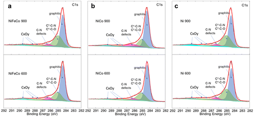 | ||
| Fig. 6 Comparison of the XPS C1s signal for (a) Ni–Fe–Co 600 and Ni–Fe–Co 900, (b) Ni–Co 600 and Ni–Co 900, and c) Ni 600 and Ni 900. | ||
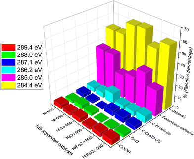 | ||
| Fig. 7 Histogram of the relative percentages of C1s species for the Ni-based KJB-supported electrocatalysts collected by the integration of the deconvoluted peaks provided in Fig. 6. | ||
2.5 XAS results and analysis
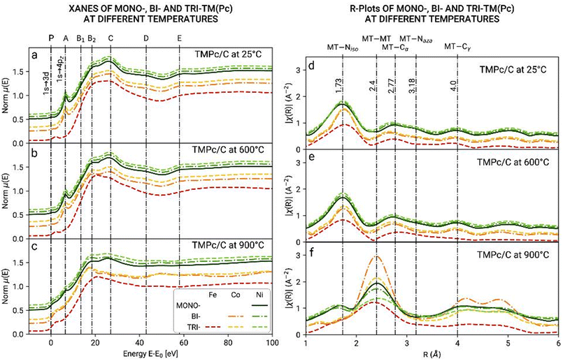
Ex situ XAS analysis of the electrocatalysts Ni, Ni–Co and Ni–Fe–Co pyrolyzed at 600 °C and 900 °C was carried out. XAS measurements were performed to study the oxidation, folding and evolution of the chemical environment of the singular and alloyed TMs (Fe, Co, or Ni). XANES and EXAFS spectra were analyzed using the Athena software (Demeter package).55 The data were acquired around the K absorption edge for Ni in the energy range centered at the edge nominal value (namely E0(Ni) = 8333 eV), in a range that spans the energies from (E0 – 300) to (E0 + 1000 eV). For Fe and Co, the ranges are limited to E0 + 600 eV due to the interference of the borders of Co and Ni (E0(Fe) = 7112 eV and E0(Co) = 7709 eV). The XANES data were normalized at E–E0. In this way, the same features were observed in the same energetic value (Fig. 8). On the top axis, the features common to phthalocyanine samples were marked, as reported by Rossi et al.56Fig. 8a and b show the spectra of the samples collected at room temperature and after being heated at 600 °C. All of the XANES spectra except for those referring to the Fe K-edge (red) show the features of the phthalocyanine molecules, in particular the peak A2, assigned to the 1s to 4p transition and the pre-edge peak, A1, which is assigned to the 1s to 3d dipole forbidden (quadrupole) transition, better shown in the subplots on the bottom-right.56,57
The Fe spectra, on the contrary, did not show the A2 peak. The pre-edge was shifted from 0 to 3 eV, and the other features also appeared less resolved (see the B2, D and E bands). The pre-edge peaks observed on the iron spectra had the same energy observed in other iron oxides (α- and γ-Fe2O3 and Fe3O4) (Fig. S3†). Instead, in the heated sample (600 °C and 900 °C), the Fe spectrum showed the 1s to 4p transition peak, although with very low intensity with respect to the other transition metals. The different XANES spectra for iron suggested a different geometry, with the symmetry changing from D4h to C4v, and the change of the structure from planar to square pyramidal with the bonding of an oxygen atom.58
The XANES spectra collected on the pyrolyzed samples show a change in the profiles, reflecting a change in the structure around the transition metals. Fig. 8d–f show the EXAFS spectra in the R space, wherein the top x-axis displays the assignments of the different peaks considering the possible environments (phthalocyanine and metallic).56,59–61Fig. 8d and e show the features related to the phthalocyanine molecule: TM–Niso, TM–Cα, TM–Naza, and TM–Cγ bonds. Fig. 8f shows the formation of metallic bonds (TM–TM) during thermal treatment with the appearance of a new peak at around 2.4 Å. It can be inferred then that metal nanoparticles are formed at a temperature between 600 °C and 900 °C.
Linear combination fitting (LCF) analysis of the XANES spectra of the pyrolyzed samples at 900 °C (Fig. S4†) also shows the formation of metallic bonds. Indeed, the measured spectra could be reproduced by combining the spectrum collected on the Ni-based electrocatalysts heated at 600 °C with the metal spectrum. For Co, an acceptable fit cannot be obtained without using CoO, suggesting that Co is also present in this form (Table S3†).
XANES spectra do not allow us to distinguish between the TM–N2, TM–N3, and TM–N4 bonds. This would be theoretically possible with FT-EXAFS refinements, but the presence of different kinds of foldings in the samples makes it really difficult to reliably perform the fitting of the EXAFS spectra. However, in the pyrolyzed Ni and Fe, the LCFs show that new metal bondings are created in all of the systems analyzed, while Co is the only metal to be also oxidized. The fitted percentages for the metallic component are nearly the same for all of the samples (between 40% and 47%) with the exception of Co in the Ni–Co samples, for which the metallic component seems to be higher. Regarding the Pc component, we observe nearly the same percentage (around 53–60%) for Fe and Ni, but a much lower value for Co, as the oxide also is formed. This fact suggests that in any case, cobalt seems to be more prone to react, even though it is converted both in its metallic and oxide forms.
2.6 Electrochemical measurements
| Sample | Overpotential (V) |
|---|---|
| Ni (30%) 900 | 0.32 |
| Ni (30%) 600 | 0.34 |
| Ni (20%) 900 | 0.35 |
| Ni (20%) 600 | 0.46 |
| Ni (15%) 900 | 0.40 |
| Ni (15%) 600 | 0.47 |
| Ni (10%) 900 | 0.44 |
| Ni (10%) 600 | 0.50 |
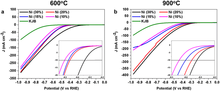
Initially, the NiPc used as a precursor for the synthesis of the Ni-based HER electrocatalyst varied between 10 wt% and 30 wt%. These tests were carried out in order to establish correlations between the metal content and performance. HER performances of the Ni electrocatalysts with different weight percentages (wt%) of NiPc were examined (Fig. 9). In the obtained result, the relationship between the wt% of the NiPc in the electrocatalysts and their HER performance were reported. Ni (30%) 900, which has the highest amount of NiPc wt%, showed the best performance with an overpotential of 0.32 ± 0.01 V (at −10 mA cm−2). By decreasing the amount of NiPc in samples, the overpotential increased. It was found that by increasing the NiPc wt%, the HER active sites increase too. This was mainly based on the metallic nanoparticles, as confirmed through the microscopic and spectroscopic investigations (Table 3). Meanwhile, the effects of different thermal treatment temperatures on the HER activity performance are significant. The electrocatalysts pyrolyzed at 900 °C showed much lower overpotential in comparison to the same electrocatalyst, but with a lower pyrolysis temperature (600 °C). According to the reported results in the other characterization sections, the electrocatalysts with 900 °C pyrolysis temperature possess a greater number of Ni nanoparticles, which play an important role as active sites for HER.62
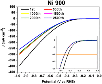
The stability test on Ni 900 (30 wt% of NiPc) is shown in Fig. 10. At 10 mA cm−2, the measured overpotential changed significantly within the first 500 cycles (it dropped from −0.32 ± 0.01 V to −0.36 ± 0.01 V). Between the 500th and 2500th cycles, the HER electrocatalytic activity remained stable. This electrocatalyst has shown considerable durability in 1 M KOH solution.
In agreement with the existing literature, the increase of Ni loading in the electrocatalyst, from 10 wt% to 30 wt%, improved the HER electrocatalytic activity.63–66 By increasing the Ni loading, the number of active sites in the electrocatalyst increased, leading to the enhancement of the Ni-based electrocatalytic activity.67 In addition, the effect of different functionalization temperatures on the electrocatalyst with different NiPc was demonstrated. The HER performance due to the functionalization at two different temperatures of 600 °C and 900 °C is not much in the electrocatalyst with 30 wt% (0.02 mV different in overpotential). However, the difference in the overpotential suddenly increased when the NiPc wt% decreased.
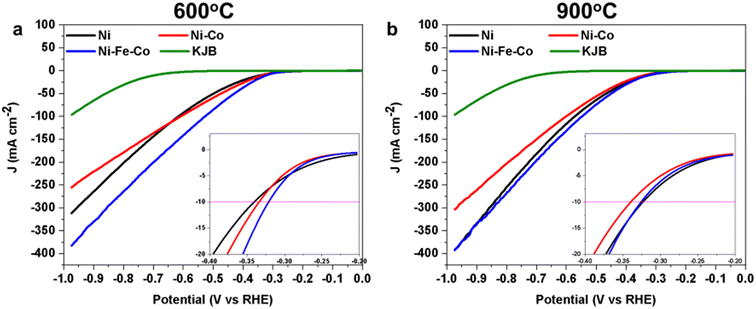
| Samples | Overpotential (V) |
|---|---|
| Ni 900 | 0.32 |
| Ni–Fe–Co 900 | 0.32 |
| Ni–Fe–Co 600 | 0.32 |
| Ni 600 | 0.34 |
| Ni–Co 900 | 0.34 |
| Ni–Co 600 | 0.34 |
The stability tests over the Ni–Co 900 and Ni–Fe–Co 900 electrocatalysts are shown in Fig. S5.† For these samples, similar to Ni 900, a performance reduction in the first 500 cycles was also observed. However, their overpotentials remained stable between the 500th and 2500th cycles, which indicates their stability in 1 M KOH solution.
For the sake of comparison, stability tests were also performed for 30 wt%. NiPc/KJB without pyrolysis treatment (Fig. S6†). However, when comparing the stability tests of the Ni samples with and without thermal treatment, valuable insights were gained regarding the positioning of the Pc rings within the electrocatalyst. The Ni 900 sample exhibited notable stability, whereas the Ni (30%) sample without thermal treatment (Fig. S6†) displayed very poor stability (less than 150 cycles). This instability might be due to the fact that the Pc rings remained on the surface of the underlying carbon structure, and were not embedded into the carbon skeleton.77
2.7 Outlook and perspectives
Bimetallic and trimetallic nitrogen-doped carbon electrocatalysts have also been studied and presented in the literature. For bimetallic electrocatalysts, Lihua Hu et al. worked on a high-density nickel–cobalt alloy embedded in nitrogen-doped carbon nanosheets. Zhang et al. also reported on the Fe–Ni bimetallic N-doped carbon framework performance for HER.68,69 Compared to these related works, with respect to the loading of NiPc and CoPc in Ni–Co electrocatalysts, the HER performances of Ni–Co 600 and Ni–Co 900 are acceptable. The effect of thermal treatment was also shown, which allowed for the formation of metallic alloy nanoparticles at high temperatures. Despite their high potential, trimetallic electrocatalysts have not received much attention and only a few studies were presented. In this way, Yuling Xu et al. worked on the Fe/Co/Ni alloy electrode. Ziqi Zhang et al. also demonstrated the real potential of trimetallic electrocatalysts, reporting their work on FeNiMo trimetallic nanoparticles encapsulated in carbon cages.32,70 However, Mo is not stable in alkaline conditions. A comparison between the obtained results and the literature is presented in Table S4 (ref. 50 and 68–76).†Many lessons were learned from the current work. Ni-based electrocatalysts were shown to be promising for HER. Nickel being the 10th group, shares a similar electronic configuration compared to Pd and Pt. Despite starting from a single atom precursor (e.g., phthalocyanine), at both 600 °C and 900 °C pyrolysis temperature, nanoparticles of different nanometric scales are present. At room temperature (no heat treatment) and 600 °C, the majority of the active sites is in the TM–Nx configuration and this is confirmed by the FT EXAFS plots. Unfortunately, XPS could not be used to quantitatively identify the metal percentage, as it was below the detection limit. Importantly, through XPS, it was possible to identify the TM–Nx relative percentage by deconvoluting the N1s spectra. Higher temperature led to the formation of a greater number of metallic nanoparticles that are beneficial for HER. This was confirmed by both TEM and EXAFS, as well as XRD.
For Ni-based monometallic electrocatalysts, higher nickel-containing precursors are also beneficial in improving the electrocatalytic activity. Future studies might further increase the amount of NiPc within the precursor. The higher electrocatalytic activity achieved with Ni 900 highlights that Ni nanoparticles, rather than Ni–Nx (atomically dispersed active site), are more efficient for HER. At 600 °C, a lower of nanoparticles with lower dimensions were also identified. However, Ni–Nx active sites were prevalent. Importantly, the low durability of the NiPc–KJB electrocatalyst without undergoing thermal treatment highlights the fact that the Pc is not embedded in the carbonaceous backbone.
Interestingly, the addition of the second metal (Co) and the third metal (Fe) has an effect on surface chemistry and electrocatalytic activity. In general, the addition of more metals within the electrocatalyst creates a more difficult situation to explain since a greater multitude of active sites are present. In fact, the TM(s)Pc exist and are embedded in the carbon structure. The nanoparticles are formed already at 600 °C and the alloys are created. FT EXAFS plots highlight the formation of nanoparticles at higher temperature. The trimetallic electrocatalyst showed similar electrocatalytic activity after the pyrolysis at 600 °C and 900 °C, and similar results were obtained compared to Ni 900. However, in bimetallic and trimetallic configurations, the weight percentage of the TM(s) was maintained at 30%. Therefore, in the trimetallic configurations, the weight percentage of Ni was only 10 wt%. Further study will focus on increasing the weight percentage of the TM(s) to enhance the quantity of TM(s) over the carbon support, which in this study, was lower than 2 wt%. We can speculate that the formation of nanoparticles (alloys and oxides) and the co-presence of multiple single active centers are beneficial for HER, acting synergistically. In this case, it is quite complicated to discriminate among the reactivity of each single active site, as a multitude of active sites are present.
All of the relevant morphological and analytical observations for Ni-based electrocatalysts are summarized in Table S5.†
3 Conclusion
The mono-/bi-/tri-metallic Ni-based electrocatalysts were synthesized by mixing the required TM–Pc with a conductive carbon backbone, and then applying the thermal treatment in a controlled atmosphere and temperature. The electrocatalysts, functionalized at two different temperatures (600 °C and 900 °C), were characterized and tested for HER. The results showed that the increase in Ni–Pc wt% in the initial mixture (from 10 wt% to 30 wt%), enhanced the HER activity. The effect of different pyrolysis temperatures on electrocatalysts was studied by XAS and HR-TEM characterization techniques, demonstrating the formation of nanoparticles, especially at higher temperatures (larger number and size). In the comparison between the two functionalized temperatures, the samples functionalized at 900 °C had a greater number of nanoparticles with larger sizes. Ni 900 (containing 30 wt% of NiPc as the initial precursor) demonstrated higher electrocatalytic activity as a monometallic electrocatalyst with an overpotential of 0.32 ± 0.01 V (at −10 mA cm−2). Excellent durability was also demonstrated in alkaline media using accelerated stress tests. It is also evident that adding a second (Co) and third (Fe) metal has a positive impact on the HER electrocatalytic activity.4 Experimental section
4.1 Materials
KJB was purchased from Nanografi Nano Technology (Turkey), and it was used as the carbon backbone for the HER electrocatalyst. Potassium hydroxide (KOH), acetone ((CH3)2CO), and Nafion® 5 wt% hydro-alcoholic solutions were purchased from Sigma-Aldrich. Nickel(II) phthalocyanine (C32H16N8Ni, named NiPc), iron(II) phthalocyanine (C32H16N8Fe, named FePc,), and cobalt(II) phthalocyanine (C32H16CoN8, named CoPc) were purchased from Acros Organics. Argon (Ar) and nitrogen (N) gases used in this study possess ultra-high purity. Ultrapure deionized water obtained from a Millipore Milli-Q system (resistivity >18 MΩ cm) was used for the experiments.4.2 Electrocatalyst synthesis
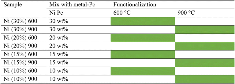
A high-energy ball miller (Emax Retsch) was used to homogeneously mix the KJB carbon with different amounts of NiPc (10, 15, 20, and 30 wt%) using a rotation rate of 400 rpm for 20 min. Then, the functionalization thermal treatment was applied over the mixed samples with two different temperatures of 900 °C and 600 °C, separately, in the controlled Ar atmosphere (UHP Ar at 100 cm3 min−1). According to the previous paper, the heating rate for increasing and decreasing the temperature was 5 °C min−1 before and after the dwell time, respectively.78 The synthesized samples are reported in Table 3.With the same approach, the TMs of choice (FePc, NiPc, and CoPc) were mixed with carbon, and functionalized with thermal treatment at two different temperatures of 600 °C and 900 °C (Table 4).
4.3 Characterization
Each spectrum was collected at room temperature with a variable energy step: a large step (5 eV) in the first 200 eV, a smaller step (0.2 eV) in the X-ray absorption near-edge structure (XANES) region, and a k-constant step of 0.03 Å−1 in the extended X-ray absorption fine-structure (EXAFS) region. The measurements for each sample were run with 3 accumulations to increase the signal-to-noise ratio. Athena software was used to normalize the XANES spectra of the samples and model compounds to the atomic background.55
The normalized XANES spectra were then analyzed through linear combination fitting (LCF) of spectra from model compounds (available from the beamline database), using the Athena software.
4.4 Hydrogen evolution reaction (HER)
In this work, the three-electrode technique with the rotating disk electrode (RDE) was applied to measure HER. A glassy carbon (GC) disk with a geometric area of 0.1963 cm2 was mounted on RDE equipment (Pine WaveVortex RDE system coupled with a Pine bipotentiostat) and used as a working electrode. For this experiment, an electrode rotation speed of 1600 rpm was maintained during the HER measurements. A saturated calomel electrode (SCE) and a Pt wire were used as a reference electrode and the counter electrode, respectively.For testing the electrochemical properties of Ni-based electrocatalysts in powder form, proper inks were required. The inks were prepared by mixing (5 mg) of electrocatalyst powder with 15 μL of 5 wt% Nafion® D-520 ionomer solution and 985 μL of isopropanol with sonication, as suggested in previous reports. The 0.6 mg cm−2 loading of the mentioned inks was achieved by depositing over a GC disk.90,91 Electrochemical measurements were performed in alkaline media (1 M KOH). Nitrogen gas was flushed into the alkaline solution from 25 min before starting the measurements to remove residual oxygen from the electrolyte solution and prevent unwanted reactivity. The measured potentials were converted into potential versus reversible hydrogen electrode (RHE) using the following equation:92
| ERHE = Eref + 0.059·pH + E0ref |
Author contributions
Conceptualization: SAM, MM, AL, CS. Data curation: SAM, MM, JO, EB, LC, AL, CLV, AZ, AG, FDF. Formal Analysis: SAM, MM, JO, EB, LC, AL, CLV, AZ. Funding acquisition: VB, AL, CS. Investigation: SAM, MM, EB, AL, CLV, AZ, LO, SP, CS. Methodology: AL, CS. Project administration: CS. Resources: SAM, JO, CLV, EB, LC, AL, AZ, FDF, MS. Supervision: LO, SP, MS, VB, AL, CS. Visualization: SAM, MM, CLV, EB, LC, AL. Writing – original draft: SAM, MM, JO, LC, AL, CLV, VB, AZ, FDF, SP, CS. Writing – review & editing: SAM, MM, JO, EB, SP, CS.Conflicts of interest
There are no conflicts to declare.Acknowledgements
S. A. M. acknowledges a Ph.D. scholarship on Green Issues from action IV.5 of the PON Research and Innovation 2014–2020 “Education and research for recovery – REACT-EU” program. C. S. would like to thank the support from ENEA – UNIMIB agreement (Procedure 1.1.3 PNRR POR H2). C. S. would like to acknowledge the Ministry of Foreign Affairs and International Cooperation – Directorate General for Cultural and Economic Promotion and Innovation (Italian Republic) within the bilateral project Italy-Israel (WE-CAT). V. B. and A. L. thank the Italian Ministry MUR for funding through the FISR 2019 project AMPERE (FISR2019_01294). The beamtime at the XAFS beamline of Elettra was provided through the proposal 20220263 and scheduled in December 2022.References
- A. Kusoglu, Chalkboard 1-the many colors of hydrogen, Electrochem. Soc. Interface, 2021, 30, 44 CrossRef.
- E. Commission, Hydrogen, https://energy.ec.europa.eu/topics/energy-systems-integration/hydrogen_en, (accessed 7 July 2023) Search PubMed.
- C. Santoro, A. Lavacchi, P. Mustarelli, V. Di Noto, L. Elbaz, D. R. Dekel and F. Jaouen, What is next in anion-exchange membrane water electrolyzers? Bottlenecks, benefits, and future, ChemSusChem, 2022, 15, e202200027 CrossRef CAS PubMed.
- M. David, C. Ocampo-Martínez and R. Sánchez-Peña, Advances in alkaline water electrolyzers: A review, J. Energy Storage, 2019, 23, 392–403 CrossRef.
- M. Rashid, M. K. Al Mesfer, H. Naseem and M. Danish, Hydrogen production by water electrolysis: a review of alkaline water electrolysis, PEM water electrolysis and high temperature water electrolysis, International Journal of Engineering and Advanced Technology, 2015, 4, 2949–8958 Search PubMed.
- M. Schalenbach, A. R. Zeradjanin, O. Kasian, S. Cherevko and K. J. Mayrhofer, A perspective on low-temperature water electrolysis–challenges in alkaline and acidic technology, Int. J. Electrochem. Sci., 2018, 13, 1173–1226 CrossRef CAS.
- M. Carmo, D. L. Fritz, J. Mergel and D. Stolten, A comprehensive review on PEM water electrolysis, Int. J. Hydrogen Energy, 2013, 38, 4901–4934 CrossRef CAS.
- S. Mukerjee, Y. Yan and H. Xu, Hydrogen at scale using low-temperature anion exchange membrane electrolyzers, Electrochem. Soc. Interface, 2021, 30, 73 CrossRef.
- Q. Li and S. Sun, Recent advances in the organic solution phase synthesis of metal nanoparticles and their electrocatalysis for energy conversion reactions, Nano Energy, 2016, 29, 178–197 CrossRef CAS.
- F. Safizadeh, E. Ghali and G. Houlachi, Electrocatalysis developments for hydrogen evolution reaction in alkaline solutions–a review, Int. J. Hydrogen Energy, 2015, 40, 256–274 CrossRef CAS.
- E. Commission, Critical raw material, https://single-market-economy.ec.europa.eu/sectors/raw-materials/areas-specific-interest/critical-raw-materials_en, (accessed 7 July 2023) Search PubMed.
- X. Zou and Y. Zhang, Noble metal-free hydrogen evolution catalysts for water splitting, Chem. Soc. Rev., 2015, 44, 5148–5180 RSC.
- S. Sultan, J. N. Tiwari, A. N. Singh, S. Zhumagali, M. Ha, C. W. Myung, P. Thangavel and K. S. Kim, Single atoms and clusters based nanomaterials for hydrogen evolution, oxygen evolution reactions, and full water splitting, Adv. Energy Mater., 2019, 9, 1900624 CrossRef.
- Q. Zhang and J. Guan, Atomically dispersed catalysts for hydrogen/oxygen evolution reactions and overall water splitting, J. Power Sources, 2020, 471, 228446 CrossRef CAS.
- M. Ďurovič, J. Hnát and K. Bouzek, Electrocatalysts for the hydrogen evolution reaction in alkaline and neutral media. A comparative review, J. Power Sources, 2021, 493, 229708 CrossRef.
- F. Ullah, K. Ayub and T. Mahmood, High performance SACs for HER process using late first-row transition metals anchored on graphyne support: A DFT insight, Int. J. Hydrogen Energy, 2021, 46, 37814–37823 CrossRef CAS.
- A. Baghban, S. Habibzadeh and F. Zokaee Ashtiani, On the evaluation of hydrogen evolution reaction performance of metal-nitrogen-doped carbon electrocatalysts using machine learning technique, Sci. Rep., 2021, 11, 21911 CrossRef CAS PubMed.
- Y. Meng, X. Huang, H. Lin, P. Zhang, Q. Gao and W. Li, Carbon-based nanomaterials as sustainable noble-metal-free electrocatalysts, Front. Chem., 2019, 7, 759 CrossRef CAS PubMed.
- L. Du, Y. Shao, J. Sun, G. Yin, J. Liu and Y. Wang, Advanced catalyst supports for PEM fuel cell cathodes, Nano Energy, 2016, 29, 314–322 CrossRef CAS.
- L. Du, G. Zhang, X. Liu, A. Hassanpour, M. Dubois, A. C. Tavares and S. Sun, Biomass-derived nonprecious metal catalysts for oxygen reduction reaction: The demand-oriented engineering of active sites and structures, Carbon Energy, 2020, 2, 561–581 CrossRef CAS.
- M. Gong, D.-Y. Wang, C.-C. Chen, B.-J. Hwang and H. Dai, A mini review on nickel-based electrocatalysts for alkaline hydrogen evolution reaction, Nano Res., 2016, 9, 28–46 CrossRef CAS.
- Q. Wang, R. Guo, Z. Wang, D. Shen, R. Yu, K. Luo, C. Wu and S. Gu, Progress in carbon-based electrocatalyst derived from biomass for the hydrogen evolution reaction, Fuel, 2021, 293, 120440 CrossRef CAS.
- J. Zhu, L. Hu, P. Zhao, L. Y. S. Lee and K.-Y. Wong, Recent advances in electrocatalytic hydrogen evolution using nanoparticles, Chem. Rev., 2019, 120, 851–918 CrossRef PubMed.
- S. A. Mirshokraee, M. Muhyuddin, R. Lorenzi, G. Tseberlidis, C. L. Vecchio, V. Baglio, E. Berretti, A. Lavacchi and C. Santoro, Litchi-derived platinum group metal-free electrocatalysts for oxygen reduction reaction and hydrogen evolution reaction in alkaline media, SusMat, 2023, 3, 248–262 CrossRef CAS.
- S. H. Ahn, S. J. Hwang, S. J. Yoo, I. Choi, H.-J. Kim, J. H. Jang, S. W. Nam, T.-H. Lim, T. Lim and S.-K. Kim, Electrodeposited Ni dendrites with high activity and durability for hydrogen evolution reaction in alkaline water electrolysis, J. Mater. Chem., 2012, 22, 15153–15159 RSC.
- Y. F. Xu, M. R. Gao, Y. R. Zheng, J. Jiang and S. H. Yu, Nickel/nickel (II) oxide nanoparticles anchored onto cobalt (IV) diselenide nanobelts for the electrochemical production of hydrogen, Angewandte Chemie, 2013, 125, 8708–8712 CrossRef.
- T. Sun, C. Zhang, J. Chen, Y. Yan, A. A. Zakhidov, R. H. Baughman and L. Xu, Three-dimensionally ordered macro−/mesoporous Ni as a highly efficient electrocatalyst for the hydrogen evolution reaction, J. Mater. Chem. A, 2015, 3, 11367–11375 RSC.
- S. A. Abbas, M. I. Iqbal, S.-H. Kim and K.-D. Jung, Catalytic activity of urchin-like Ni nanoparticles prepared by solvothermal method for hydrogen evolution reaction in alkaline solution, Electrochim. Acta, 2017, 227, 382–390 CrossRef CAS.
- T. Sun, L. Xu, D. Wang and Y. Li, Metal organic frameworks derived single atom catalysts for electrocatalytic energy conversion, Nano Res., 2019, 12, 2067–2080 CrossRef CAS.
- L. Du, L. Luo, Z. Feng, M. Engelhard, X. Xie, B. Han, J. Sun, J. Zhang, G. Yin and C. Wang, Nitrogen–doped graphitized carbon shell encapsulated NiFe nanoparticles: A highly durable oxygen evolution catalyst, Nano Energy, 2017, 39, 245–252 CrossRef CAS.
- Y. Shen, Y. Zhou, D. Wang, X. Wu, J. Li and J. Xi, Nickel–copper alloy encapsulated in graphitic carbon shells as electrocatalysts for hydrogen evolution reaction, Adv. Energy Mater., 2018, 8, 1701759 CrossRef.
- Y. Xu, Y. Liu, X. Zhang, K. Liu, R. Wang, Y. Yang, Z. Fang and J. Chen, Enhanced hydrogen evolution performance by nanoarchitectonics of Fe/Co alloy electrode beyond Fe/Co/Ni alloy electrode, Int. J. Hydrogen Energy, 2023, 48, 757–765 CrossRef CAS.
- Y. Yang, Z. Lin, S. Gao, J. Su, Z. Lun, G. Xia, J. Chen, R. Zhang and Q. Chen, Tuning electronic structures of nonprecious ternary alloys encapsulated in graphene layers for optimizing overall water splitting activity, ACS Catal., 2017, 7, 469–479 CrossRef CAS.
- Y. Xiao, Y. Liu, Z. Tang, L. Wu, Y. Zeng, Y. Xu and Y. He, Porous Ni–Cr–Fe alloys as cathode materials for the hydrogen evolution reaction, RSC Adv., 2016, 6, 51096–51105 RSC.
- L. Yu, T. Lei, B. Nan, J. Kang, Y. Jiang, Y. He and C. Liu, Mo doped porous Ni–Cu alloy as cathode for hydrogen evolution reaction in alkaline solution, RSC Adv., 2015, 5, 82078–82086 RSC.
- A. Zaffora, F. Di Franco, D. Pupillo, B. Seminara, G. Tranchida and M. Santamaria, Highly active and stable NiCuMo electrocatalyst supported on 304 stainless steel porous transport layer for hydrogen evolution in alkaline water electrolyzer, Adv. Sustainable Syst., 2023, 7, 2200486 CrossRef CAS.
- A. C. Ferrari, J. C. Meyer, V. Scardaci, C. Casiraghi, M. Lazzeri, F. Mauri, S. Piscanec, D. Jiang, K. S. Novoselov and S. Roth, Raman spectrum of graphene and graphene layers, Phys. Rev. Lett., 2006, 97, 187401 CrossRef CAS PubMed.
- C. Beny-Bassez and J. Rouzaud, Characterization of carbonaceous materials by correlated electron and optical microscopy and Raman microspectroscopy, Scanning Electron Microsc., 1984, 1985, 11 Search PubMed.
- D. Testa, G. Zuccante, M. Muhyuddin, R. Landone, A. Scommegna, R. Lorenzi, M. Acciarri, E. Petri, F. Soavi and L. Poggini, Giving new life to waste cigarette butts: Transformation into platinum group metal-free electrocatalysts for oxygen reduction reaction in acid, neutral and alkaline Environment, Catalysts, 2023, 13, 635 CrossRef CAS.
- O. Beyssac, J.-N. Rouzaud, B. Goffe, F. Brunet and C. Chopin, Graphitization in a high-pressure, low-temperature metamorphic gradient: A Raman microspectroscopy and HRTEM study, Contrib. Mineral. Petrol., 2002, 143, 19–31 CrossRef CAS.
- B. Wang, X. Li, B. Luo, J. Yang, X. Wang, Q. Song, S. Chen and L. Zhi, Pyrolyzed bacterial cellulose: a versatile support for lithium ion battery anode materials, Small, 2013, 9, 2399–2404 CrossRef CAS PubMed.
- L. M. Malard, M. H. Guimarães, D. L. Mafra and A. Jorio, Group-theory analysis of electrons and phonons in N-layer graphene systems, Phys. Rev. B: Condens. Matter Mater. Phys., 2009, 79, 125426 CrossRef.
- L. G. Cançado, A. Jorio, E. M. Ferreira, F. Stavale, C. A. Achete, R. B. Capaz, M. V. D. O. Moutinho, A. Lombardo, T. Kulmala and A. C. Ferrari, Quantifying defects in graphene via Raman spectroscopy at different excitation energies, Nano Lett., 2011, 11, 3190–3196 CrossRef PubMed.
- C. Casiraghi, S. Pisana, K. Novoselov, A. K. Geim and A. Ferrari, Raman fingerprint of charged impurities in graphene, Appl. Phys. Lett., 2007, 91, 233108 CrossRef.
- K. Saenger, J. Tsang, A. Bol, J. Chu, A. Grill and C. Lavoie, In situ x-ray diffraction study of graphitic carbon formed during heating and cooling of amorphous-C/Ni bilayers, Appl. Phys. Lett., 2010, 96, 153105 CrossRef.
- M. Hu, J. Reboul, S. Furukawa, N. L. Torad, Q. Ji, P. Srinivasu, K. Ariga, S. Kitagawa and Y. Yamauchi, Direct carbonization of Al-based porous coordination polymer for synthesis of nanoporous carbon, J. Am. Chem. Soc., 2012, 134, 2864–2867 CrossRef CAS PubMed.
- N. Bozovic, I. Bozovic and J. Misewich, X-ray nanocrystallography of individual carbon nanotubes, Nano Lett., 2008, 8, 4477–4482 CrossRef CAS PubMed.
- D. Graf, F. Molitor, K. Ensslin, C. Stampfer, A. Jungen, C. Hierold and L. Wirtz, Spatially resolved Raman spectroscopy of single-and few-layer graphene, Nano Lett., 2007, 7, 238–242 CrossRef CAS PubMed.
- L. Zhang, Y. Jia, X. Yan and X. Yao, Activity origins in nanocarbons for the electrocatalytic hydrogen evolution reaction, Small, 2018, 14, 1800235 CrossRef PubMed.
- M. Muhyuddin, N. Zocche, R. Lorenzi, C. Ferrara, F. Poli, F. Soavi and C. Santoro, Valorization of the inedible pistachio shells into nanoscale transition metal and nitrogen codoped carbon-based electrocatalysts for hydrogen evolution reaction and oxygen reduction reaction, Mater. Renewable Sustainable Energy, 2022, 11, 131–141 CrossRef.
- A. S. Rajan, S. Sampath and A. K. Shukla, An in situ carbon-grafted alkaline iron electrode for iron-based accumulators, Energy Environ. Sci., 2014, 7, 1110–1116 RSC.
- Z. Yang, Z. Yu, H. Wei, X. Xiao, Z. Ni, B. Chen, Y. Deng, S. N. Habisreutinger, X. Chen and K. Wang, Enhancing electron diffusion length in narrow-bandgap perovskites for efficient monolithic perovskite tandem solar cells, Nat. Commun., 2019, 10, 4498 CrossRef PubMed.
- S. Sun, G. Zhang, N. Gauquelin, N. Chen, J. Zhou, S. Yang, W. Chen, X. Meng, D. Geng and M. N. Banis, Single-atom catalysis using Pt/graphene achieved through atomic layer deposition, Sci. Rep., 2013, 3, 1775 CrossRef.
- R. Gokhale, Y. Chen, A. Serov, K. Artyushkova and P. Atanassov, Direct synthesis of platinum group metal-free Fe-NC catalyst for oxygen reduction reaction in alkaline media, Electrochem. Commun., 2016, 72, 140–143 CrossRef CAS.
- B. Ravel and M. Newville, ATHENA, ARTEMIS, HEPHAESTUS: data analysis for X-ray absorption spectroscopy using IFEFFIT, J. Synchrotron Radiat., 2005, 12, 537–541 CrossRef CAS PubMed.
- G. Rossi, F. d'Acapito, L. Amidani, F. Boscherini and M. Pedio, Local environment of metal ions in phthalocyanines: K-edge X-ray absorption spectra, Phys. Chem. Chem. Phys., 2016, 18, 23686–23694 RSC.
- Q. Chang, Y. Liu, J.-H. Lee, D. Ologunagba, S. Hwang, Z. Xie, S. Kattel, J. H. Lee and J. G. Chen, Metal-coordinated phthalocyanines as platform molecules for understanding isolated metal sites in the electrochemical reduction of CO2, J. Am. Chem. Soc., 2022, 144, 16131–16138 CrossRef CAS PubMed.
- J. Guo, X. Yan, Q. Liu, Q. Li, X. Xu, L. Kang, Z. Cao, G. Chai, J. Chen and Y. Wang, The synthesis and synergistic catalysis of iron phthalocyanine and its graphene-based axial complex for enhanced oxygen reduction, Nano Energy, 2018, 46, 347–355 CrossRef CAS.
- V. Bambagioni, C. Bianchini, J. Filippi, A. Lavacchi, W. Oberhauser, A. Marchionni, S. Moneti, F. Vizza, R. Psaro and V. Dal Santo, Single-site and nanosized Fe–Co electrocatalysts for oxygen reduction: Synthesis, characterization and catalytic performance, J. Power Sources, 2011, 196, 2519–2529 CrossRef CAS.
- J. Zang, F. Wang, Q. Cheng, G. Wang, L. Ma, C. Chen, L. Yang, Z. Zou, D. Xie and H. Yang, Cobalt/zinc dual-sites coordinated with nitrogen in nanofibers enabling efficient and durable oxygen reduction reaction in acidic fuel cells, J. Mater. Chem. A, 2020, 8, 3686–3691 RSC.
- A. Alsudairi, J. Li, N. Ramaswamy, S. Mukerjee, K. Abraham and Q. Jia, Resolving the iron phthalocyanine redox transitions for ORR catalysis in aqueous media, J. Phys. Chem. Lett., 2017, 8, 2881–2886 CrossRef CAS PubMed.
- J. Ding, H. Yang, S. Zhang, Q. Liu, H. Cao, J. Luo and X. Liu, Advances in the electrocatalytic hydrogen evolution reaction by metal nanoclusters-based materials, Small, 2022, 18, 2204524 CrossRef CAS PubMed.
- J. Salmones, J. Wang, M. Valenzuela, E. Sánchez and A. Garcia, Pore geometry influence on the deactivation behavior of Ni-based catalysts for simultaneous production of hydrogen and nanocarbon, Catal. Today, 2009, 148, 134–139 CrossRef CAS.
- A. Venugopal, S. N. Kumar, J. Ashok, D. H. Prasad, V. D. Kumari, K. Prasad and M. Subrahmanyam, Hydrogen production by catalytic decomposition of methane over Ni/SiO2, Int. J. Hydrogen Energy, 2007, 32, 1782–1788 CrossRef CAS.
- T. Choudhary, C. Sivadinarayana, C. C. Chusuei, A. Klinghoffer and D. Goodman, Hydrogen production via catalytic decomposition of methane, J. Catal., 2001, 199, 9–18 CrossRef CAS.
- S. K. Saraswat and K. Pant, Thermo catalytic decomposition of methane: A novel approach to COx free hydrogen and carbon nanotubes production over Ni/SiO2 catalyst, Energy, 2012, 1, 2 Search PubMed.
- S. Karimi, F. Bibak, F. Meshkani, A. Rastegarpanah, J. Deng, Y. Liu and H. Dai, Promotional roles of second metals in catalyzing methane decomposition over the Ni-based catalysts for hydrogen production: A critical review, Int. J. Hydrogen Energy, 2021, 46, 20435–20480 CrossRef CAS.
- L. Hu, J. Shi, Z. Peng, Z. Zheng, H. Dong and T. Wang, A high-density nickel–cobalt alloy embedded in nitrogen-doped carbon nanosheets for the hydrogen evolution reaction, Nanoscale, 2022, 14, 6202–6211 RSC.
- Z. Zhang, L. Cong, Z. Yu, L. Qu and W. Huang, Facile synthesis of Fe–Ni bimetallic N-doped carbon framework for efficient electrochemical hydrogen evolution reaction, Mater. Today Energy, 2020, 16, 100387 CrossRef.
- Z. Zhang, L. Cong, Z. Yu, L. Qu, M. Qian and W. Huang, FeNiMo trimetallic nanoparticles encapsulated in carbon cages as efficient hydrogen evolution reaction electrocatalysts, Mater. Adv., 2020, 1, 54–60 RSC.
- H. Wang, H.-W. Lee, Y. Deng, Z. Lu, P.-C. Hsu, Y. Liu, D. Lin and Y. Cui, Bifunctional non-noble metal oxide nanoparticle electrocatalysts through lithium-induced conversion for overall water splitting, Nat. Commun., 2015, 6, 7261 CrossRef CAS PubMed.
- C. Zhu, A. L. Wang, W. Xiao, D. Chao, X. Zhang, N. H. Tiep, S. Chen, J. Kang, X. Wang and J. Ding, In situ grown epitaxial heterojunction exhibits high-performance electrocatalytic water splitting, Adv. Mater., 2018, 30, 1705516 CrossRef PubMed.
- X. Wang, W. Li, D. Xiong, D. Y. Petrovykh and L. Liu, Bifunctional nickel phosphide nanocatalysts supported on carbon fiber paper for highly efficient and stable overall water splitting, Adv. Funct. Mater., 2016, 26, 4067–4077 CrossRef CAS.
- C. Lei, Y. Wang, Y. Hou, P. Liu, J. Yang, T. Zhang, X. Zhuang, M. Chen, B. Yang and L. Lei, Efficient alkaline hydrogen evolution on atomically dispersed Ni–N x Species anchored porous carbon with embedded Ni nanoparticles by accelerating water dissociation kinetics, Energy Environ. Sci., 2019, 12, 149–156 RSC.
- Z. Bai, S. Li, J. Fu, Q. Zhang, F. Chang, L. Yang, J. Lu and Z. Chen, Metal-organic framework-derived Nickel Cobalt oxysulfide nanocages as trifunctional electrocatalysts for high efficiency power to hydrogen, Nano Energy, 2019, 58, 680–686 CrossRef CAS.
- K. E. Salem, A. A. Saleh, G. E. Khedr, B. S. Shaheen and N. K. Allam, Unveiling the optimal interfacial synergy of plasma-modulated trimetallic Mn-Ni-Co phosphides: Tailoring deposition ratio for complementary water splitting, Energy Environ. Mater., 2023, 6, e12324 CAS.
- W. Orellana, C. Z. Loyola, J. F. Marco and F. Tasca, Evidence of carbon-supported porphyrins pyrolyzed for the oxygen reduction reaction keeping integrity, Sci. Rep., 2022, 12, 8072 CrossRef CAS PubMed.
- E. Giordano, E. Berretti, L. Capozzoli, A. Lavacchi, M. Muhyuddin, C. Santoro, I. Gatto, A. Zaffora and M. Santamaria, Boosting DMFC power output by adding sulfuric acid as a supporting electrolyte: Effect on cell performance equipped with platinum and platinum group metal-free cathodes, J. Power Sources, 2023, 563, 232806 CrossRef CAS.
- C. Lo Vecchio, A. S. Aricò and V. Baglio, Application of low-cost Me-NC (Me= Fe or Co) electrocatalysts derived from edta in direct methanol fuel cells (DMFCs), Materials, 2018, 11, 1193 CrossRef PubMed.
- C. L. Vecchio, A. S. Aricò, G. Monforte and V. Baglio, EDTA-derived CoNC and FeNC electro-catalysts for the oxygen reduction reaction in acid environment, Renewable Energy, 2018, 120, 342–349 CrossRef.
- S. Chen, F. Bi, K. Xiang, Y. Zhang, P. Hao, M. Li, B. Zhao and X. Guo, Reactive template-derived CoFe/N-doped carbon nanosheets as highly efficient electrocatalysts toward oxygen reduction, oxygen evolution, and hydrogen evolution, ACS Sustainable Chem. Eng., 2019, 7, 15278–15288 CrossRef CAS.
- R. Mercado, C. Wahl, J. En Lu, T. Zhang, B. Lu, P. Zhang, J. Q. Lu, A. L. Allen, J. Z. Zhang and S. Chen, Nitrogen-doped porous carbon cages for electrocatalytic reduction of oxygen: Enhanced performance with iron and cobalt dual metal centers, ChemCatChem, 2020, 12, 3230–3239 CrossRef CAS.
- X.-W. Song, S. Zhang, H. Zhong, Y. Gao, L. A. Estudillo-Wong, N. Alonso-Vante, X. Shu and Y. Feng, FeCo nanoalloys embedded in nitrogen-doped carbon nanosheets/bamboo-like carbon nanotubes for the oxygen reduction reaction, Inorg. Chem. Front., 2021, 8, 109–121 RSC.
- S. H. Liu and H. C. Kuo, Core-shell FeCo N-doped biocarbons as stable electrocatalysts for oxygen reduction reaction in fuel cells, Int. J. Energy Res., 2021, 45, 8285–8295 CrossRef CAS.
- Y. Zhou, Y. Zhang, X. Xu, S. Zhao, Z. Guo, K.-H. Wu, C. Tan and Z. Wang, Bimetallic metal-organic framework derived metal-carbon hybrid for efficient reversible oxygen electrocatalysis, Front. Chem., 2019, 7, 747 CrossRef CAS PubMed.
- E. Gul, L. Riva, H. K. Nielsen, H. Yang, H. Zhou, Q. Yang, Ø. Skreiberg, L. Wang, M. Barbanera and M. Zampilli, Substitution of coke with pelletized biocarbon in the European and Chinese steel industries: An LCA analysis, Appl. Energy, 2021, 304, 117644 CrossRef CAS.
- A. Serov, K. Artyushkova, N. I. Andersen, S. Stariha and P. Atanassov, Original mechanochemical synthesis of non-platinum group metals oxygen reduction reaction catalysts assisted by sacrificial support method, Electrochim. Acta, 2015, 179, 154–160 CrossRef CAS.
- N. Ramaswamy and S. Mukerjee, Influence of inner-and outer-sphere electron transfer mechanisms during electrocatalysis of oxygen reduction in alkaline media, J. Phys. Chem. C, 2011, 115, 18015–18026 CrossRef CAS.
- A. Di Cicco, G. Aquilanti, M. Minicucci, E. Principi, N. Novello, A. Cognigni and L. Olivi, Novel XAFS capabilities at ELETTRA synchrotron light source, J. Phys.: Conf. Ser., 2009, 190, 012043 CrossRef.
- M. Muhyuddin, A. Friedman, F. Poli, E. Petri, H. Honig, F. Basile, A. Fasolini, R. Lorenzi, E. Berretti and M. Bellini, Lignin-derived bimetallic platinum group metal-free oxygen reduction reaction electrocatalysts for acid and alkaline fuel cells, J. Power Sources, 2023, 556, 232416 CrossRef CAS.
- M. Muhyuddin, D. Testa, R. Lorenzi, G. M. Vanacore, F. Poli, F. Soavi, S. Specchia, W. Giurlani, M. Innocenti and L. Rosi, Iron-based electrocatalysts derived from scrap tires for oxygen reduction reaction: Evolution of synthesis-structure-performance relationship in acidic, neutral and alkaline media, Electrochim. Acta, 2022, 433, 141254 CrossRef CAS.
- G. Jerkiewicz, Standard and reversible hydrogen electrodes: Theory, design, operation, and applications, ACS Catal., 2020, 10, 8409–8417 CrossRef CAS.
- M. Muhyuddin, J. Filippi, L. Zoia, S. Bonizzoni, R. Lorenzi, E. Berretti, L. Capozzoli, M. Bellini, C. Ferrara and A. Lavacchi, Waste face surgical mask transformation into crude oil and nanostructured electrocatalysts for fuel cells and electrolyzers, ChemSusChem, 2022, 15, e202102351 CrossRef CAS PubMed.
- S. A. Mirshokraee, M. Muhyuddin, R. Morina, L. Poggini, E. Berretti, M. Bellini, A. Lavacchi, C. Ferrara and C. Santoro, Upcycling of waste lithium-cobalt-oxide from spent batteries into electrocatalysts for hydrogen evolution reaction and oxygen reduction reaction: A strategy to turn the trash into treasure, J. Power Sources, 2023, 557, 232571 CrossRef CAS.
Footnote |
| † Electronic supplementary information (ESI) available. See DOI: https://doi.org/10.1039/d3im00058c |
| This journal is © Institute of Process Engineering of CAS 2023 |

