A tight squeeze: geometric effects on the performance of three-electrode electrochemical-aptamer based sensors in constrained, in vivo placements†
Kaylyn K.
Leung
 ae,
Julian
Gerson
 be,
Nicole
Emmons
 be,
Brian
Roehrich
 a,
Elsi
Verrinder
 ae,
Lisa C.
Fetter
 ce,
Tod E.
Kippin
 bd and
Kevin W.
Plaxco
 *ace
*ace
aDepartment of Chemistry and Biochemistry, University of California Santa Barbara, Santa Barbara, CA 93106, USA. E-mail: kwp@ucsb.edu
bDepartment of Psychological and Brain Sciences, University of California, Santa Barbara, CA 93106, USA
cBiomolecular Sciences and Engineering, University of California, Santa Barbara, California 93106, USA
dDepartment of Molecular Cellular and Developmental Biology, University of California, Santa Barbara, CA 93106, USA
eCenter for Bioengineering, University of California Santa Barbara, Santa Barbara, CA 93106, USA
First published on 1st March 2023
Abstract
Electrochemical, aptamer-based (EAB) sensors are the first molecular monitoring technology that is (1) based on receptor binding and not the reactivity of the target, rendering it fairly general, and (2) able to support high-frequency, real-time measurements in situ in the living body. To date, EAB-derived in vivo measurements have largely been performed using three electrodes (working, reference, counter) bundled together within a catheter for insertion into the rat jugular. Exploring this architecture, here we show that the placement of these electrodes inside or outside of the lumen of the catheter significantly impacts sensor performance. Specifically, we find that retaining the counter electrode within the catheter increases the resistance between it and the working electrode, increasing the capacitive background. In contrast, extending the counter electrode outside the lumen of the catheter reduces this effect, significantly enhancing the signal-to-noise of intravenous molecular measurements. Exploring counter electrode geometries further, we find that they need not be larger than the working electrode. Putting these observations together, we have developed a new intravenous EAB architecture that achieves improved performance while remaining short enough to safely emplace in the rat jugular. These findings, though explored here with EAB sensors may prove important for the design of many electrochemical biosensors.
Introduction
The ability to measure the concentrations of clinically relevant molecular targets continuously and in real time in the living body would significantly advance our ability to diagnose, monitor, treat, and understand disease. Towards this goal, we are developing electrochemical aptamer-based (EAB) sensors: a reagentless, reversible molecular sensing platform that performs well in vivo. In these, the binding of a specific target induces a conformational change in an electrode-attached, redox-reporter-modified aptamer (Fig. 1a), resulting in an easily detectable change in the redox reporter's electron transfer kinetics that we typically monitor using square wave voltammetry.1–6 Because this conformation-linked signaling mechanism does not rely on any specific chemical or enzymatic reactivity of the target itself, the development of EAB sensors against new targets is relatively easy. With this signal transduction mechanisms that mimics those found in naturally occurring chemoperception systems, EAB sensors also support real-time, high-frequency measurements in complex sample matrices, including unprocessed bodily fluids.2,7–10 Building on these advantages, EAB sensors have already been used to measure the rise and fall of more than a half-dozen therapeutics,1,2,6,11 drugs of abuse, and metabolites5 in real time in the blood of live rats. The resulting high-frequency, real-time molecular measurements have even been shown to support closed-loop, feedback-controlled drug delivery;1,12 an advance that could usher in a new era in which pharmacological therapies can be delivered with unprecedented precision.13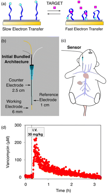 | ||
| Fig. 1 (a) Electrochemical aptamer-based (EAB) sensors are comprised of redox-reporter-modified, conformation-shifting aptamers attached to a gold electrode via a self-assembled monolayer. The phrase “conformation-shifting” refers to an aptamer that has been reengineered such that target binding reversibly alters its shape, changing in turn the rate of electron transfer of the attached redox reporter. (b) EAB sensors support molecular measurements in vivo. To do so in the rat jugular, we have used bundled, catheter-enclosed sensors. In one architecture, for example, a gold wire working electrode, a platinum wire counter electrode, and a chloride-anodized silver wire reference electrode are staggered within a 20-gauge catheter such that the counter electrode remains within the catheter, and half of the reference electrode and all of the working electrode extend into the lumen of the vein. (c) This is then surgically inserted into the external jugular vein of an anesthetized rat. (d) Using this and related architectures we have monitored the plasma concentrations of multiple drugs and metabolites in live rats.1,2,5,6,11 Shown here, for example, are 14 s-resolved plasma vancomycin measurements performed using the described architecture emplaced in the rat jugular after an intravenous injection of the drug. | ||
In our prior work, we have deployed in vivo EAB sensors as a 3-electrode system consisting of a gold wire working electrode modified with the target-recognizing aptamer, a chloride-anodized silver wire reference electrode (RE), and a platinum wire counter electrode (CE). These are individually insulated using heat-shrink polytetrafluoroethylene (PTFE) and then bundled together in a staggered fashion and placed in a catheter. To date, we have published work with in vivo EAB sensors using two specific arrangements following this general scheme. In one, 75 μm diameter wires were used for all three electrodes and only the gold working electrode extends out of the catheter and into the vein.1,2,5,6,11,14 In a second, we employed 200 μm diameter wires placed in the catheter (Fig. 1b) such that half of the reference electrode and all of the working electrode extend out of the catheter and into the vein (Fig. 1c).15 In both cases, we retained the counter electrode within the catheter, so as to reduce the length of the sensor and thus avoid interfering with the heart.
As extensive prior literature demonstrates and as shown here, the in vivo EAB architectures we have employed support unprecedentedly highly-time resolved measurements of plasma drug and metabolite levels (e.g., Fig. 1d). This said, however, several aspects of the fabrication of intravenous EAB sensors remain unexamined, suggesting that their performance could be further improved. Specifically, here we explore the extent to which the relative placement of the three electrodes in an intra-catheter EAB sensor alters the device's performance, with the expectation that better understanding this will guide us towards improved signal-to-noise ratios and smaller, less invasive devices.
Results and discussion
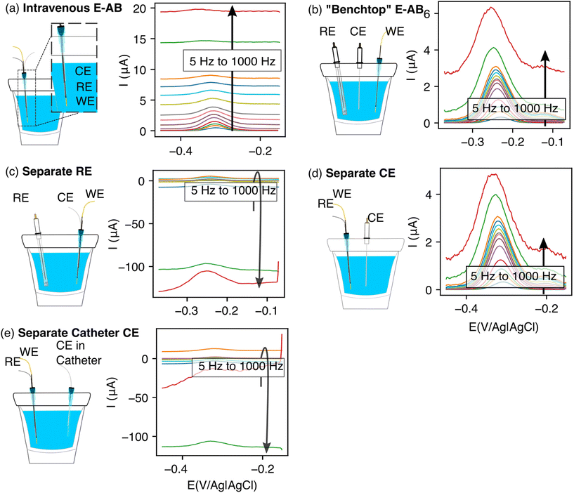
The performance of EAB sensors depends strongly on whether their electrodes are placed inside or outside of a catheter. To see this, we first used in vitro experiments to compare a “bundled-electrodes” intravenous architecture, in which the counter and reference electrodes are retained within a catheter and the working electrode extends out of the lumen, with a sensor comprised of three physically separated, catheter-free electrodes. Doing so, we find that the baseline currents associated with the bundled architecture are (1) high and (2) a relatively strong function of square wave frequency (Fig. 2a). This behavior contrasts with that seen in the “benchtop” EAB sensor where the reference and counter electrodes are separated from the bundle (Fig. 2b). The high baselines associated with the bundled sensor reduce the peak currents, suggesting the details of the placement of EAB electrodes within a catheter may harm sensor performance.We next set out to determine which of the three electrodes in an EAB sensor are responsible for the high baseline currents associated with our initial bundled architecture. As our first experiment, we characterized a sensor in which the counter and working electrodes were placed in the catheter, but the reference electrode (here a commercial, glass-frit Ag/AgCl reference) was physically separated. Under these conditions, the baseline currents we observe are as high and as strongly frequency dependent as those seen with the initial bundled architecture (Fig. 2c). Following this, we separated the counter electrode, leaving the reference and the working electrode in the catheter. With this case, we recover the low baselines and reduce the frequency dependence observed for the separated electrodes architecture (Fig. 2d). Building on these observations, we next separated the counter electrode but placed it in a second catheter. The baseline currents we observed for this architecture were again as high and as strongly frequency dependent as those of the initial bundled architecture (Fig. 2e).
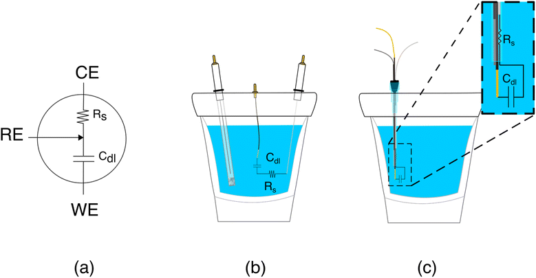
The poorer performance seen when the counter electrode is placed inside a catheter arises due to the high solution resistance this architecture produces. To see why this may be true, consider the working principles of a 3-electrode electrochemical cell. In the absence of redox reactions, this cell can be modeled as a series RC circuit comprised of a resistor of resistance Rs, which captures the resistance of the solution between the working and counter electrodes, and a capacitor of capacitance Cdl, which captures the capacitance of the electric double layer (Fig. 3a and b).16 How rapidly the capacitor charges (i.e., the time it takes for the formation of the double layer) depends on a time constant given by the product RsCdl. This, in turn, determines the current observed at a specific time after the potential is applied, which defines the baseline current at a given square wave frequency (in square wave voltammetry, the current is sampled at the end of each square wave). Specifically, smaller time constants (i.e., faster charging) decrease the baseline current seen at higher square wave frequencies (i.e., shorter time delays before current sampling). In contrast, longer time constants increase the baseline currents. For architectures including a catheter-enclosed counter electrode, the small cross section of the solution within the catheter ensures that Rs is much larger, increasing the product RsCdl and, in turn, the baseline currents increase substantially as a function of square wave frequencies (Fig. 4a).
 | ||
| Fig. 4 As evident with multiple electrochemical techniques, the electrochemical behavior of EAB sensors depends strongly on whether the counter electrode is positioned inside or outside of the catheter. (a) For example, employing square wave voltammetry (here at 100 Hz and 25 mV amplitude), the baseline current is significantly higher, and the peak height is smaller when the counter electrode is retained within the catheter (blue) versus when it is placed outside of the catheter (red). (b) In chronoamperometry, we apply a −0.45 V potential step and observe the resulting current transiently. When the counter electrode is placed inside the catheter (blue curve), the response time constant of the electrode is notably reduced. (c) Differences in the Nyquist plot seen when we characterized our architectures using electrochemical impedance spectroscopy further supports our arguments. Specifically, when the counter electrode is placed inside the catheter (blue curve), the x intercept, which indicates the solution resistance (Rs), increases 60-fold (Table 1). In contrast, the increase in the imaginary impedance (on the y axis) is so similar for both cases resulting in Cdl values that are within error of one another (Table 1). | ||
Characterization of our various sensor architectures using chronoamperometry and impedance spectroscopy supports the above conclusions. Specifically, using chronoamperometry to measure the sensor's temporal response to a potential jump we find that, as expected given the above arguments, the time constants observed when the counter electrode is free in solution are shorter than those seen when the counter electrode is contained within a catheter (Fig. 4b). Using electrochemical impedance to distinguish between the resistive components (arising due to Rs) and capacitive components (arising due to Cdl) of our sensors produces a similar picture.17 Specifically, Rs increases and Cdl is largely unchanged when we move the counter electrode from free in solution to constrained within a catheter. In a Nyquist plot, in which the imaginary impedance is plotted as a function of the real impedance (Fig. 4c), we find that the x intercept, which is indicative of Rs, is significantly higher when the counter electrode is inside the catheter than when it is outside. In contrast, the capacitive contributions remain unchanged (Table 1).
| Parameter | Counter electrode inside the catheter | Counter electrode outside the catheter |
|---|---|---|
| R s | 6540 ± 350 Ω | 104 ± 4 Ω |
| C dl | 0.49 ± 0.02 μF | 0.50 ± 0.02 μF |
| χ 2 | 1.0313 | 0.0091524 |
With our realization that sensor performance improves when the counter electrode is placed outside the catheter, we next designed a 2nd bundled sensor architecture in which the reference electrode is placed inside of the catheter and the counter and working electrodes both extend beyond the catheter tip (Fig. 5). As noted above, however, a potential problem associated with such architectures is that, using the 1.5 cm counter electrode length we usually employ, the bare electrodes extend at least 2 cm beyond the catheter tip, risking interactions between the counter electrode and the heart (Fig. 1c). Thus motivated, we next explored the extent to which we can reduce the length of the exposed counter electrode without unduly degrading sensor performance. To our surprise, given the generally held requirement for three electrode cells that the counter electrode must be larger than the area of the working electrode,18–20 we found no significant differences in sensor performance when we shortened the counter electrode from 1.5 cm to 3 mm (Fig. 5). We believe that this (to us unexpected) result arises due to the thiol passivating layer on our working electrode, which reduces the double layer capacitance of the working electrode. Irrespective of its origins, however, the practical upshot of this observation is that we can employ a short enough counter electrode to ensure that the sensor does not reach the heart.
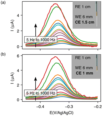 | ||
| Fig. 5 Reducing the counter electrode size by 15-fold does not significantly affect the performance of EAB sensors. Specifically, we obtain near identical voltammograms whether using a (a) 1.5 cm counter electrode or (b) one that is just 1 mm in length. For results at intermediate counter electrode lengths, see Fig. S1.† Insets illustrate the length of counter electrode exposed in each geometry. | ||
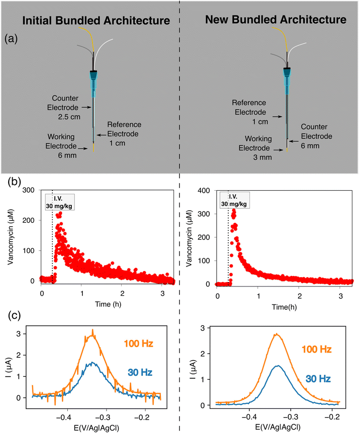
Building on the above observations we next designed an intravenous sensor architecture employing a fully exposed, 6 mm-long counter electrode (Fig. 6a). Unfortunately, however, we observed transient shorting when the potential was first applied to the sensor. We suspect that this occurred because the tight fit of these wires inside the catheter leaves the PTFE shrink-tubing we used to insulate the electrodes susceptible to microtears, leading to short-circuiting between the reference and working electrodes. Fortunately, replacing the 200 μm diameter silver and 250 μm diameter platinum wires with 125 μm diameter wires (Fig. 6a) eliminated this effect.
Extending the counter electrode outside of the catheter improves the signal-to-noise of intravenous EAB sensors. To illustrate this, we monitored plasma vancomycin levels upon a 30 mg kg−1 intravenous dose using both our initial architecture and the above-described, new architecture (Fig. 6a). The 1.0 μM noise (defined as the standard deviations of the fluctuations around the baseline prior to dosing) associated with the new architecture under these experimental conditions is approximately 3 times smaller than that we see for our first bundled architecture (Fig. 6b). One source of this discrepancy is the fact that voltammograms collected in the rat jugular using this new architecture exhibit less noise associated with the heartbeat (Fig. 6c). Given the results reported here, we suspect that this noise occurs as the animal's pulse dilates and constricts the vein and, thus, the catheter, causing the Rs to vary periodically for our first bundled architecture.
The effects we observe may be relevant to 3-electrode EAB sensor deployments beyond the bundled intravenous sensors explored here. For example, there has been growing interest in less-invasive EAB sensors deployed as subdermal or intradermal microneedles.21,22 In these scenarios, there is limited liquid or limited electrolyte present, which could similarly lead to high resistances between the counter electrode and working electrode. Consistent with our findings, as a result of the limited electrolyte present, others have measured high signal to noise when such EAB sensors are placed in the dermal tissue of a rat,21 suggesting that reducing the resistance between the working and counter electrodes could improve the performance of such sensors.
Conclusions
Here we have shown that changing the relative placements of their three electrodes can significantly improve the performance of catheter-bound in vivo sensors. Specifically, the voltammogram baselines were lower and peak heights higher for architectures in which the counter electrode emerges from the lumen of the catheter. We attribute this difference to a reduction in the resistance between the working electrode and counter electrodes. We have also shown that the EAB counter electrode can be significantly smaller than the working electrode without harming sensor performance. Finally, we combined these two observations to create a new, intravenous EAB sensor architecture that achieves significantly improved performance when placed in the jugular veins of live rats.Conflicts of interest
The authors declare the following competing financial interest(s): One author (K. W. P.) has a financial interest in and serves on the scientific advisory boards of two companies attempting to commercialize EAB sensors. Following the completion of this work, two authors (K. L. and J. G.) became employees of a company attempting to commercialize EAB sensors.Acknowledgements
The in vivo experiments were aided by J. Gibson and K. Honeywell, who helped with monitoring and termination for multiple in vivo experiments. The primary author greatly thanks K. Son for helping accurately diagnose the cause of the shorting. Advice, feedback and general electrochemical knowledge was supplemented by Prof. L. Sepunaru. This work was supported by the NIH (R01AI145206), by the Office of Naval Research (N00014-20-1-2164), by the Otis Williams Postdoctoral Fellowship Fund (KL) and the Department of Defense through the National Defense Science and Engineering Graduate Fellowship (NE).References
- P. Dauphin-Ducharme, K. Yang, N. Arroyo-Currás, K. L. Ploense, Y. Zhang, J. Gerson, M. Kurnik, T. E. Kippin, M. N. Stojanovic and K. W. Plaxco, Electrochemical Aptamer-Based Sensors for Improved Therapeutic Drug Monitoring and High-Precision, Feedback-Controlled Drug Delivery, ACS Sens., 2019, 4(10), 2832–2837, DOI:10.1021/acssensors.9b01616.
- N. Arroyo-Currás, J. Somerson, P. A. Vieira, K. L. Ploense, T. E. Kippin and K. W. Plaxco, Real-Time Measurement of Small Molecules Directly in Awake, Ambulatory Animals, Proc. Natl. Acad. Sci. U. S. A., 2017, 114(4), 645–650, DOI:10.1073/pnas.1613458114.
- P. Dauphin-Ducharme and K. W. Plaxco, Maximizing the Signal Gain of Electrochemical-DNA Sensors Graphical Abstract HHS Public Access, Anal. Chem., 2016, 88(23), 11654–11662, DOI:10.1021/acs.analchem.6b03227.
- B. S. Ferguson, D. A. Hoggarth, D. Maliniak, K. Ploense, R. J. White, N. Woodward, K. Hsieh, A. J. Bonham, M. Eisenstein, T. E. Kippin, K. W. Plaxco and H. T. Soh, Real-Time, Aptamer-Based Tracking of Circulating Therapeutic Agents in Living Animals, Sci. Transl. Med., 2013, 5(213), 213ra165, DOI:10.1126/scitranslmed.3007095.
- K. W. Plaxco, A. Idili, J. Gerson and T. Kippin, Seconds-Resolved, in Situ Measurements of Plasma Phenylalanine Disposition Kinetics in Living Rats, Anal. Chem., 2021, 93(8), 4023–4032, DOI:10.1021/acs.analchem.0c05024.
- A. Idili, N. Arroyo-Currás, K. L. Ploense, A. T. Csordas, M. Kuwahara, T. E. Kippin, K. W. Plaxco, N. Arroyo-Curras, K. L. Ploense, A. T. Csordas, M. Kuwahara, T. E. Kippin and K. W. Plaxco, Seconds-Resolved Pharmacokinetic Measurements of the Chemotherapeutic Irinotecan: In Situ in the Living Body, Chem. Sci., 2019, 10(35), 8164–8170, 10.1039/c9sc01495k.
- J. Das, K. B. Cederquist, A. A. Zaragoza, P. E. Lee, E. H. Sargent and S. O. Kelley, An Ultrasensitive Universal Detector Based on Neutralizer Displacement, Nat. Chem., 2012, 4(8), 642–648, DOI:10.1038/nchem.1367.
- F. Patolsky, Y. Weizmann and I. Willner, Redox-Active Nucleic-Acid Replica for the Amplified Bioelectrocatalytic Detection of Viral DNA, J. Am. Chem. Soc., 2002, 124(5), 770–772, DOI:10.1021/ja0119752.
- J. A. Hansen, R. Mukhopadhyay, J. Hansen and K. V. Gothelf, Femtomolar Electrochemical Detection of DNA Targets Using Metal Sulfide Nanoparticles, J. Am. Chem. Soc., 2006, 128(12), 3860–3861, DOI:10.1021/ja0574116.
- J. J. Gooding, Electrochemical DNA Hybridization Biosensors, Electroanalysis, 2002, 14(17), 1149–1156, DOI:10.1002/1521-4109(200209)14:17<1149::AID-ELAN1149>3.0.CO;2-8.
- N. Arroyo-Currás, P. Dauphin-Ducharme, G. Ortega, K. L. Ploense, T. E. Kippin and K. W. Plaxco, Subsecond-Resolved Molecular Measurements in the Living Body Using Chronoamperometrically Interrogated Aptamer-Based Sensors, ACS Sens., 2018, 3(2), 360–366, DOI:10.1021/acssensors.7b00787.
- N. Arroyo-Currás, G. Ortega, D. A. Copp, K. L. Ploense, Z. A. Plaxco, T. E. Kippin, J. P. Hespanha and K. W. Plaxco, High-Precision Control of Plasma Drug Levels Using Feedback-Controlled Dosing, ACS Pharmacol. Transl. Sci., 2018, 1(2), 110–118, DOI:10.1021/acsptsci.8b00033.
- T. M. Rawson, D. O’Hare, P. Herrero, S. Sharma, L. S. P. Moore, E. de Barra, J. A. Roberts, A. C. Gordon, W. Hope, P. Georgiou, A. E. G. Cass and A. H. Holmes, Delivering Precision Antimicrobial Therapy through Closed-Loop Control Systems, J. Antimicrob. Chemother., 2018, 73(4), 835–843, DOI:10.1093/jac/dkx458.
- A. M. Downs, J. Gerson, M. N. Hossain, K. Ploense, M. Pham, H. B. Kraatz, T. Kippin and K. W. Plaxco, Nanoporous Gold for the Miniaturization of in Vivo Electrochemical Aptamer-Based Sensors, ACS Sens., 2021, 6(6), 2299–2306, DOI:10.1021/ACSSENSORS.1C00354.
- J. Chung, L. Sepunaru and K. W. Plaxco, On the Disinfection of Electrochemical Aptamer-Based Sensors, ECS Sens. Plus, 2022, 1(1), 011604, DOI:10.1149/2754-2726/ac60b2.
- A. J. Bard and L. R. Faulkner, Double-Layer Capacitance and Charging Current in Electrochemical Measurements, in Electrochemical Methods: Fundamentals and Applications, 2001, pp. 14–18 Search PubMed.
- A. J. Bard and L. R. Faulkner, Techniques Based On Concepts Of Impedance, in Electrochemical Methods: Fundamentals and Applications, 2001, pp. 368–416 Search PubMed.
- P. Westbroek, Analytical Electrochemistry in Textiles, Woodhead Publishing, 2005, pp. 3–36. DOI:10.1533/9781845690878.1.1.
- N. Elgrishi, K. J. Rountree, B. D. McCarthy, E. S. Rountree, T. T. Eisenhart and J. L. Dempsey, A Practical Beginner's Guide to Cyclic Voltammetry, J. Chem. Educ., 2018, 95(2), 197–206, DOI:10.1021/acs.jchemed.7b00361.
- M. Ciobanu, J. P. Wilburn, M. L. Krim and D. E. Cliffel, Fundamentals, in Handbook of Electrochemistry, Elsevier, 2007, pp. 3–29. DOI:10.1016/B978-044451958-0.50002-1.
- Y. Wu, F. Tehrani, H. Teymourian, J. Mack, A. Shaver, M. Reynoso, J. Kavner, N. Huang, A. Furmidge, A. Duvvuri, Y. Nie, L. M. Laffel, F. J. Doyle, M. E. Patti, E. Dassau, J. Wang and N. Arroyo-Currás, Microneedle Aptamer-Based Sensors for Continuous, Real-Time Therapeutic Drug Monitoring, Anal. Chem., 2022, 94(23), 8335–8345, DOI:10.1021/acs.analchem.2c00829.
- S. Lin, X. Cheng, J. Zhu, B. Wang, D. Jelinek, Y. Zhao, T. Y. Wu, A. Horrillo, J. Tan, J. Yeung, W. Yan, S. Forman, H. A. Coller, C. Milla and S. Emaminejad, Wearable Microneedle-Based Electrochemical Aptamer Biosensing for Precision Dosing of Drugs with Narrow Therapeutic Windows, Sci. Adv., 2022, 8(38), eabq4539, DOI:10.1126/SCIADV.ABQ4539/.
Footnote |
| † Electronic supplementary information (ESI) available. See DOI: https://doi.org/10.1039/d2an02096c |
| This journal is © The Royal Society of Chemistry 2023 |

