 Open Access Article
Creative Commons Attribution 3.0 Unported Licence
A simple decagram-scale synthesis of an atomically dispersed, hierarchically porous Fe–N–C catalyst for acidic ORR†
Burak
Koyuturk‡
a,
Eliyahu M.
Farber‡
 b,
Friedrich E.
Wagner
c,
Tim-Patrick
Fellinger
 *ad and
David
Eisenberg
 *b
*b
aChair of Technical Electrochemistry, Department of Chemistry and Catalysis Research Center, Technical University of Munich, Lichtenbergstraße 4, D-85748 Garching, Germany
bSchulich Faculty of Chemistry, Grand Technion Energy Program, Russell Berrie Nanotechnology Institute, Technion–Israel Institute of Technology, Technion City, Haifa, 3200003, Israel. E-mail: eisenberg@technion.ac.il
cDepartment of Physics, Technical University of Munich, D-85748 Garching, Germany
dBundesanstalt für Materialforschung und -prüfung (BAM), Unter den Eichen 44-46, 12203 Berlin, Germany. E-mail: tim-patrick.fellinger@bam.de
First published on 18th May 2022
Abstract
Carbons doped with iron and nitrogen (Fe–N–Cs) are highly promising electrocatalysts for energy conversion reactions in the oxygen, nitrogen and carbon cycles. Containing no platinum group metals, they nevertheless compete with platinum-based catalysts in crucial fuel cell reactions, such as oxygen reduction in acid. Yet deployment of Fe–N–Cs in fuel cells requires also a flow-enhancing pore structure, and a scalable synthesis procedure – a rarely-met combination of requirements. We now report such a simple synthesis of over 10 g of an Fe–N–C catalyst with high activity towards oxygen reduction in acid. Atomically-dispersed Fe–N4 active sites were designed orthogonally and simultaneously with hierarchical micro-, meso- and macroporosity, by exploiting a dual role of magnesium ions during pyrolysis. Combining the “active site imprinting” and “self-templating” strategies in a single novel magnesium iminodiacetate precursor yielded a catalyst with high specific surface area (SSA > 1600 m2 g−1), a flow-enhancing hierarchical porosity, and high relative abundance of the most desirable D1-type Fe–N4 sites (43%, by Mössbauer spectroscopy at 4.2 K). Despite the relatively low iron contents, the catalysts feature halfwave potentials up to 0.70 V vs. RHE at pH 1 and a mass activity of 1.22 A g−1 at 0.8 V vs. RHE in RDE experiments. Thanks to the simple and scalable synthesis, this active and stable catalyst may serve as a workhorse in academic and industrial research into atomically-dispersed ORR electrocatalysis.
Introduction
Proton-exchange-membrane fuel cells (PEMFCs) are efficient and clean power devices, an integral part of the vision of clean and sustainable energy economy. Electric PEMFC-powered vehicles running on carbon-neutral fuels (e.g. green hydrogen1) can help cut CO2 emissions and reduce our reliance on fossil fuels.2,3 To make PEMFCs commercially viable, the cathode catalysts for the oxygen reduction reaction (ORR) must use as little platinum group metals (PGMs) as possible.4,5 Research into PGM-free ORR electrocatalysts began in 1964, when Jasinski reported molecular cobalt phthalocyanine to be active towards the ORR in alkaline medium.6 Recent years have witnessed an exponential increase in the number of heterogeneous ORR electrocatalysts, based on carbon and either free or low in PGMs.7–13 Lately, single atom catalysts (SACs) have emerged as a new frontier in ORR electrocatalysis research.14–19 Containing atomically dispersed, heteroatom-coordinated metals (e.g. Fe–N4) on a conductive carbon matrix, such materials exhibit outstanding ORR activity and selectivity in acid and alkaline media in comparison to other PGM-free catalysts.18–26To translate the promise of SACs into practical fuel cell cathodes, highly active catalytic sites are not enough.27 First, to achieve high power density, the reactants and products must move fast through the material. This calls for hierarchically porous carbons, combining high surface areas for active site exposure, with a network of flow-enabling larger pores.28 Second, the materials must be synthesized reproducibly and in large quantity, to enable extensive fundamental investigations and to allow for commercial scale-up. Most current syntheses of Fe–N–C SACs yield catalytic powders on the ten milligram scale,12,18,20,21,29–36 whereas a hundred gram scale is needed to power automotive fuel cell stacks at current performance levels.37–39 Large scale syntheses of Fe–N–C materials have been reported recently,40,41 albeit relying on commercial activated carbons, rich in micropores yet lacking significant flow-enhancing meso- or macroporosity. To the best of our knowledge, the only hierarchically porous, atomically dispersed Fe–N–C commercially produced on a gram scale is the proprietary material developed by Serov and Atanassov et al., and offered by Pajarito Powder, USA.19,42–45
We now report a scalable, simple, decagram-scale synthesis of an active and stable Fe–N–C SAC for the ORR in acid (E½ = 0.70 V vs. RHE). Our goal is to simplify the synthesis without losing activity, to allow researchers in academia and industry access to gram quantities of an efficient ORR catalyst. To this end, we successfully united two templating strategies in a single heat-treatment. The first strategy is active site imprinting, a novel approach towards well-defined, atomically-dispersed iron-nitrogen moieties in carbon electrocatalysts.26,46,47 In this method, N-coordinated non-precious cations such as Mg2+ or Zn2+ can be embedded via N-coordination into a carbon surface during pyrolysis. Then, ion-exchange (transmetalation) with iron yields iron–nitrogen moieties, at temperatures low enough (80 °C) to prevent carbothermal reduction of iron and the undesirable generation of Fe(0) or Fe3C phases.46–49
In parallel, in order to create a flow-enhancing hierarchical porosity, we relied on the self-templating strategy.50–55 In this method, pyrolysis of a metal–organic coordination polymer yields a carbon skeleton embedded with metal oxide or carbonate particles; removal of the inorganic phases by simple washing leaves behind a heteroatom-doped, hierarchically porous carbon with a high specific surface area (SSA). Alkaline earth metals (Mg2+, Ba2+) are most commonly used for this application.50,52–55 Iron itself, however, cannot be employed to yield single atom Fe–N–Cs directly, since carbothermal reduction of iron would result in inorganic iron phases as undesirable side products, leading to pore blocking49 and corrosive Fenton activity.56
Thus, we took advantage the ability of Mg to act as a dual template, both imprinting active sites46 and templating hierarchical porosity.52–54 By pyrolyzing a novel and inexpensive magnesium iminodiacetate precursor, followed by washing and low-temperature transmetalation, we obtained a hierarchically porous, graphitized carbon, containing a significant proportion (43%) of desirable “surface Fe–N4” (also called “D1”) sites.57–59 Moreover, the synthesis was successfully scaled-up from the hundred mg to over ten gram scale. We provide an active, stable, and scalable material with the potential to become a useful workhorse for academic and industrial research groups interested in PGM-free, hierarchically porous, atomically-dispersed ORR catalysts.
Results and discussion
Magnesium iminodiacetate (Mg-IDA), a metal–organic coordination polymer (MOCP), was precipitated in hot water from basic magnesium carbonate and iminodiacetic acid (NH(CH2COOH)2, IDA) at a 1![[thin space (1/6-em)]](https://www.rsc.org/images/entities/char_2009.gif) :
:![[thin space (1/6-em)]](https://www.rsc.org/images/entities/char_2009.gif) 1 molar ratio. During pyrolysis, the iminodiacetate ligand is carbonized into an N-doped carbon, while the magnesium carboxylates decompose to give MgO nanoparticles and CO2.60 Exothermic crystallization of MgO was observed by thermal gravimetric analysis between 750 and 1000 °C (Fig. S1†).53,60 This temperature range is thus useful for pyrolysis, due to expected variations in the MgO particle sizes and degrees of agglomeration.52–54 Mg-IDA was pyrolyzed at a range of temperatures (Tpyrolysis = 800, 850, 900, 950 °C), resulting in fine black powders (denoted as Mg/NC_Tpyrolysis). The carbons are highly porous, foam-like, and dotted with bright particles, as seen by scanning electron microscopy (SEM, Fig. 1a). The particle sizes are in the 10–100 nm range, and are composed of crystalline MgO (powder X-ray diffraction, XRD, Fig. S2†). Scherrer analysis reveals typical coherent scattering lengths of 8–10 nm (Fig. S2,† inset). This is smaller than the particle size, indicating agglomeration and/or defects.55 The MgO was removed by HCl washing, leaving behind a sponge-like, hierarchically porous morphology (Fig. 1b), expected to be beneficial for mass transport during electrocatalysis. Importantly, the carbon texture is robust across the 800–950 °C temperature range. Transmetalation was then carried out in an anhydrous methanolic solution of FeCl2, under reflux at 80 °C. The resulting Fe–N–Cs are named [Fe(NC_Tpyrolysis)], adapting on the nomenclature used in coordination chemistry.
1 molar ratio. During pyrolysis, the iminodiacetate ligand is carbonized into an N-doped carbon, while the magnesium carboxylates decompose to give MgO nanoparticles and CO2.60 Exothermic crystallization of MgO was observed by thermal gravimetric analysis between 750 and 1000 °C (Fig. S1†).53,60 This temperature range is thus useful for pyrolysis, due to expected variations in the MgO particle sizes and degrees of agglomeration.52–54 Mg-IDA was pyrolyzed at a range of temperatures (Tpyrolysis = 800, 850, 900, 950 °C), resulting in fine black powders (denoted as Mg/NC_Tpyrolysis). The carbons are highly porous, foam-like, and dotted with bright particles, as seen by scanning electron microscopy (SEM, Fig. 1a). The particle sizes are in the 10–100 nm range, and are composed of crystalline MgO (powder X-ray diffraction, XRD, Fig. S2†). Scherrer analysis reveals typical coherent scattering lengths of 8–10 nm (Fig. S2,† inset). This is smaller than the particle size, indicating agglomeration and/or defects.55 The MgO was removed by HCl washing, leaving behind a sponge-like, hierarchically porous morphology (Fig. 1b), expected to be beneficial for mass transport during electrocatalysis. Importantly, the carbon texture is robust across the 800–950 °C temperature range. Transmetalation was then carried out in an anhydrous methanolic solution of FeCl2, under reflux at 80 °C. The resulting Fe–N–Cs are named [Fe(NC_Tpyrolysis)], adapting on the nomenclature used in coordination chemistry.
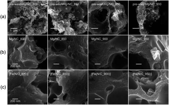 | ||
| Fig. 1 Scanning electron micrographs of (a) MgO@NC as pyrolyzed, (b) Mg/NC after washing, (c) [Fe(N/C)] after transmetalation. | ||
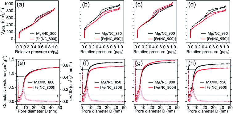
To quantify the hierarchical porosity, the carbons were characterized by N2 physisorption porosimetry at 77 K, both before and after transmetalation (Fig. 2a–d). All isotherms belong to the H4 type.61 A steep increase in gas uptake at low p/p0 values reveals the presence of micropores (<2 nm). The subsequent slope, the indicated plateau, and desorption hysteresis arise from N2 physisorption in mesopores (2–50 nm), while the further uptake at high p/p0 values indicates additional macropores (>50 nm). The steep desorption at p/p0 ≈ 0.4 is characteristic for cavitation/blocking effects, indicating that the mesopores are connected via small bottlenecks.61,62 All carbons exhibit high SSAs and large total pore volumes (1100–1700 m2 g−1, Table 1), as calculated by Brunauer–Emmett–Teller (BET) theory. Both the high SSA values and the significant mesopore content make these carbons promising for mass transport during electrocatalysis. Pore size distributions, calculated from the adsorption isotherms using a quenched-solid DFT model for slit, cylindrical and spherical pores, shows three similar peaks in the carbons, centred at diameters of 1.0, 3.5 and 6.5 nm (Fig. 2e–h).
| Sample | SSA (m2 g−1) | S micro (m2 g−1) | S meso (m2 g−1) | V micro (cm3 g−1) | V total (cm3 g−1) |
|---|---|---|---|---|---|
| Mg/NC_800 | 1175 | 372 | 803 | 0.14 | 1.34 |
| [Fe(N/C_800)] | 1116 | 183 | 933 | 0.08 | 1.35 |
| Mg/NC_850 | 1780 | 686 | 1094 | 0.27 | 1.52 |
| [Fe(N/C_850)] | 1569 | 477 | 1092 | 0.20 | 1.40 |
| Mg/NC_900 | 1565 | 563 | 1002 | 0.22 | 1.49 |
| [Fe(N/C_900)] | 1614 | 471 | 1143 | 0.20 | 1.62 |
| Mg/NC_950 | 1708 | 666 | 1042 | 0.25 | 1.46 |
| [Fe(N/C_950)] | 1496 | 505 | 991 | 0.20 | 1.31 |
Importantly, the isotherms retain their shape following transmetalation, revealing that the ion exchange does not harm the hierarchically porous morphology of the catalysts. The micropore surface area (Smicro) is reduced slightly (by 3–12%) following the ion-exchange, due to some blocking of micropores by residual iron oxides (see below). For [Fe(N/C_800)], [Fe(N/C_850)] and [Fe(N/C_950)] the characteristic pore sizes remain unchanged after transmetalation. Overall, the active site imprinting is orthogonal to the design of the hierarchically porosity of the carbon support.
To be active in electrocatalysis, carbons must be electrically conductive, which requires a sufficient degree of graphitization. The latter can be estimated by Raman spectroscopy, using the intensity ratio between the D band (ν = 1350 cm−1, typical of defects) and the G band (ν = 1580 cm−1, typical to graphitic regions).53 All Mg/NC samples exhibit similar Raman spectra (Fig. 3), with graphitic domains ranging in length (La) between 13.4–14.4 nm (Table 2). This degree of graphitization indicates sufficient and similar conductivities in the material.53,63
| Sample | Surface elemental composition (at%) | Surface nitrogen distribution (%) | Graphitization | |||||||
|---|---|---|---|---|---|---|---|---|---|---|
| C | N | O | Pyridinic | Pyrrolic | Metal-N | Graphitic | N–O | I D/IG | L a 67 (nm) | |
| Mg/NC_800 | 87.90 | 6.61 | 5.49 | 35.92 | 30.38 | 18.17 | 11.85 | 3.69 | 1.4 | 13.7 |
| [Fe(N/C)_800] | 87.76 | 6.60 | 5.64 | 31.51 | 32.73 | 21.36 | 11.60 | 2.80 | ||
| Mg/NC_850 | 88.20 | 6.29 | 5.51 | 34.39 | 29.44 | 21.47 | 11.01 | 3.69 | 1.38 | 13.9 |
| [Fe(N/C)_850] | 87.16 | 6.04 | 6.81 | 31.11 | 28.05 | 25.95 | 10.60 | 4.28 | ||
| Mg/NC_900 | 89.44 | 6.78 | 3.77 | 31.95 | 24.53 | 23.63 | 14.50 | 5.39 | 1.43 | 13.4 |
| [Fe(N/C)_900] | 88.93 | 5.63 | 5.44 | 32.97 | 22.30 | 24.40 | 14.16 | 6.18 | ||
| Mg/NC_950 | 91.11 | 5.02 | 3.87 | 28.57 | 26.43 | 18.56 | 17.13 | 9.31 | 1.33 | 14.4 |
| [Fe(N/C)_950] | 90.06 | 4.81 | 5.12 | 30.00 | 23.28 | 23.73 | 17.10 | 5.89 | ||
Nitrogen surface functionalities play a key role in forming the active sites. X-ray photoelectron spectra (XPS) in the N 1s region were collected for the Mg–N–Cs, and deconvoluted into five different types of nitrogen (Fig. 4a–d): pyridinic (398.2–398.8 eV), metal-bound (399.4–400.0 eV), pyrrolic (400.1–400.5 eV), graphitic (401.2–401.5 eV) and oxidized nitrogen species (>403 eV).64,65 The effect of pyrolysis temperature on the surface concentrations of nitrogen, carbon and oxygen is summarized in Table 2. The total surface nitrogen content is constant between 800 °C and 900 °C, and decreases at 950 °C. With increasing pyrolysis temperature, the proportion of edge-located nitrogen atoms (pyridinic, pyrrolic) decreases, and that of graphitic nitrogen increases. This reveals the lateral growth of graphitic nanostructures, and relates to enhanced conductivity.46,52,64 Metal–nitrogen bonds are found at the surface both before and after transmetalation, indicating the coordination of Mg2+ and then Fe2+ to nitrogen moieties. Following transmetalation, the N 1s spectra retain their general shape (Fig. 4e–h), as well as the surface concentration of graphitic nitrogen atoms (Table 2). The relative proportion of Me–N bonds rises with the pyrolysis temperature and peaks at 900 °C, indicating an optimal coordination environment at this temperature. Trace amounts of Mg (0.13–0.22 wt%) remain in the bulk of the acid washed material, as revealed by inductively coupled plasma mass spectrometry (ICP-MS, Table S1†), and supporting the case for a strong Mg–N4 coordination.66
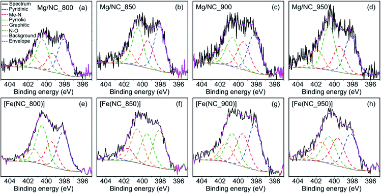 | ||
| Fig. 4 Deconvoluted XPS spectra in the N 1s region, for the (a)–(d) Mg/NC and (e)–(h) [Fe(N/C)] samples. | ||
Finally, the robustness of the carbon composition along the pyrolysis was investigated by heating Mg/NC_800 in argon from room temperature to 950 °C in a thermogravimetric setup coupled to mass spectrometry (Fig. S3†). Following the initial steep mass decrease due to desorption of physisorbed gases, CO2 signals (m/z = 44, 45, 22) and NO signals (m/z = 30) evolve only after 700 °C. This slow and steady loss of carboxylic and nitrogen groups corroborates the SEM observations that the carbons are not significantly changed over a broad pyrolysis range, and that their synthesis is robust.
[Fe(NC)_900] was selected for further analysis and tests, exhibiting the highest proportion of metal-bound nitrogens (24.4%) and the highest SSA (1614 m2 g−1). To observe the finest nanopores (<5 nm), high-resolution transmission electron microscopy (HR-TEM) was performed for Mg/NC_900 and [Fe(N/C_900)] (Fig. 5a and b). The carbon is homogeneously nanoporous, corroborating the hierarchical porosity, and promising fast flow to active sites during catalysis. The dispersion of nitrogen and iron dopants in the transmetalated sample was mapped using a high angle annular dark field (HAADF) detector and energy dispersive X-ray spectroscopy (EDS) in scanning transmission electron microscopy (STEM) mode.49,68 The micrographs reveal atomically dispersed Fe atoms, along with an even distribution of nitrogen atoms, overall revealing a successful ion-exchange process toward Fe–N–C SACs (Fig. 5c–f). Some Fe-based nanoparticles (2–4 nm) are also observed as side products of the transmetalation, albeit at a low concentration. Such iron-containing nanoparticles explain the slight decrease in micropore area that follows transmetalation (Table 1), as they likely block micropores.
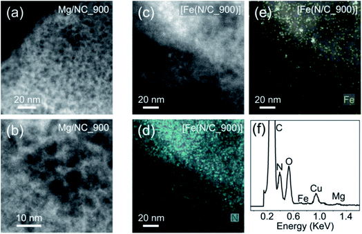 | ||
| Fig. 5 HRTEM micrographs of (a) and (b) Mg/NC_900; (c) [Fe(N/C_900)]; HR-STEM mapping of (d) nitrogen and (e) iron in [Fe(N/C_900)]; (f) EDS spectrum of [Fe(N/C_900)]. | ||
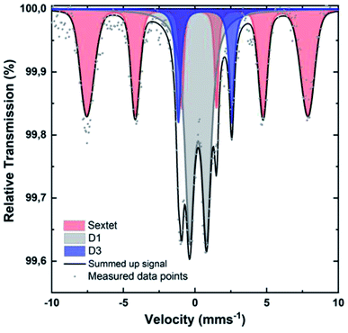
To identify the iron species in [Fe(NC_900)], the sample was studied by Mössbauer spectroscopy at 4.2 K. Recently, room temperature measurements were shown to potentially cause overestimation of Fe–N4 moieties, since oxidic iron nanoparticles/clusters may appear as doublets at room temperature.47,69 Such oxidic nanoclusters reveal their characteristic magnetism in measurements at 4.2 K, where a magnetic hyperfine splitting can be observed because the particles are magnetically ordered and superparamagnetic relaxations are blocked. The 4.2 K Mössbauer spectrum of [Fe(NC_900)] exhibits a sextet and two doublets (Fig. 6). The sextet is assigned to oxidic Fe nanoparticles, which may have formed through iron coordination with oxygen surface groups, or during the aqueous acid work-up that follows the transmetalation step. The two quadrupole doublets in the spectrum correspond to the doublets named D1 and D3 in the literature47 according to their isomer shift and electric quadrupole interaction (Table S2†). The D3 doublets, typically arising from high spin Fe2+,47 were reported in room temperature Mössbauer measurements of Fe–N–C electrocatalysts, but could not be correlated to ORR activity. In contrast, the intensity of the D1 doublets correlates positively with the ORR activity.57–59 Importantly, D1 contributes as much as 43% to the total iron content of 0.8 wt% of the studied catalyst, which could be calculated from the total absorption of the Mössbauer spectrum (Tables S2–S4†), making [Fe(NC_900)] a promising electrocatalyst with many utilizable single atom catalytic sites.
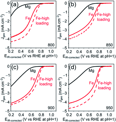
The electrocatalytic ORR activity of the obtained Fe–N–C was tested in a standard three electrode rotating disc electrode (RDE) setup in 0.1 M HClO4 electrolyte and compared to the respective Mg/NCs. The thin-film electrodes were prepared by drop-casting, at catalyst loadings of 200 and 500 μg cm−2. All four Mg/NC samples exhibited poor ORR activities: the linear sweep voltammograms (LSVs) show onset potentials of 0.7 V vs. RHE at pH = 1, and low current densities of 1.5–2.5 mA cm−2 at 0.2 V (Fig. 7). Transmetalation with iron improved the ORR activity drastically: the kinetic region is shifted positively by more than 300 mV, the onset potential increases to 0.83 V, and current densities at 0.2 V are in the range of 4 mA cm−2. The kinetics remain limiting over the potential range. Half-wave potentials (E½), typical (though loading-dependent) ORR activity descriptors, ranged between 0.63–0.70 V vs. RHE (Table 3), indicating high ORR activity of these Fe–N–C electrocatalysts.70 The mass activities extracted from LSV curves are similar to that of commercially available Fe–N–C catalysts.71
| Sample | E ½ (V) | I m (A g−1) at 0.8 V |
|---|---|---|
| [Fe(NCs)]_800 | 0.63 | 0.36 ± 0.10 |
| [Fe(NCs)]_850 | 0.68 | 0.96 ± 0.12 |
| [Fe(NCs)]_900 | 0.69 | 0.95 ± 0.04 |
| [Fe(NCs)]_950 | 0.70 | 1.22 ± 0.11 |
The stability of the carbon electrocatalysts towards corrosion was measured for [Fe(N/C_900)] by repeated cycling experiments in an N2-saturated electrolyte. Corrosive conditions at the cathode may be caused by the start-up and shut-down of PEM fuel cells.72 The voltage was cycled between open circuit potential (OCP) and 1.4 V vs. RHE, revealing a small increase in double layer capacitance and pseudo-capacitive currents, and a slight decrease in current density after 1000 cycles (Fig. S4†).73 For carbons with such large SSA (>1100 m2 g−1), relatively large pore sizes (>6 nm), and significant oxygen content (>5.44 at% in [Fe(NC_900)] by ICP-MS), this degradation is remarkably low, indicating that carbon corrosion is very moderate.
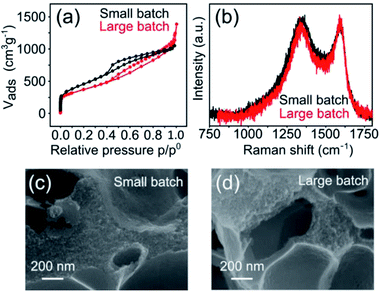
The hierarchically porous, atomically dispersed Fe–N–C electrocatalysts reported herein are also very easy to produce. To demonstrate the scalability of the synthesis, we carried out a five-fold increase in scale of the Mg-IDA precipitation, and then repeated the synthesis. A total of about 0.2 kg Mg-IDA was prepared. The next stages of the synthesis – pyrolysis at 900 °C, acid wash, drying and transmetalation in methanolic FeCl2 solution – were done in two batches, yielding 25 g of MgO@NC_900 and finally 10.1 grams of [Fe(N/C_900)]. The Raman spectra and HRSEM micrographs are identical, revealing remarkably similar degrees of graphitization and porous microstructure (Fig. 8). The isotherms are similar in shape. The large batch carbon has a lower surface area (1323 vs. 1614 m2 g−1) and a higher gas uptake near p = p0, suggesting a slightly higher degree of large meso- and small macropores. ICP-MS measurements reveal identical nitrogen content (7.8 and 7.6 wt% for the small and large batches, respectively). The electrochemical activity of the batches is also similar (Table S4†), with identical onset potentials (0.84 ± 0.01) and half-wave potentials (0.69 ± 0.005).
Conclusions
We report a simple and scalable (decagram scale) synthesis of an atomically-dispersed, hierarchically porous Fe–N–C electrocatalyst for acidic ORR. Pyrolysis of magnesium iminodiacetate yielded Mg–N4 sites that could later be transmetalated with iron (“active site imprinting”), as well as MgO nanoparticles and particle agglomerates that served as templates for meso- and macroporosity (“pore self-templating”). Thorough material characterization by XRD, HRSEM, HRTEM, XPS, Raman spectroscopy, N2 sorption and Mössbauer spectroscopy at 4.2 K revealed the structure of the active sites (43% of the iron as surface-embedded Fe–N4) and the flow-enhancing porosity of the carbon support. Rotating disk half-cell tests revealed halfwave potentials of 0.7 V vs. RHE in 0.1 M HClO4, high mass activity, and high stability against carbon corrosion. The carbon could be scaled up by a factor of 100 very simply, while conserving the morphology and activity. The straightforward synthesis of the active ORR electrocatalyst provides simple access to reasonable amounts of single-atom Fe–N–C catalysts also for researchers not specialized in synthesis.Conflicts of interest
There are no conflicts to declare.Acknowledgements
B. K. and T.-P. F. would like to thank the German Federal Ministry of Economy and Energy (BMWi) for the financial support (project: innoKA, project number: 03ET6096A) and Prof. H. Gasteiger for hosting our group. Prof. P. Zelenay is acknowledged for hosting B. K. at LANL. E. M. F. would like to thank the Nancy and Stephen Grand Technion Energy Program, the Daniel Foundation and the Gutwirth Foundation for graduate research fellowships. D. E. dedicated the article to the living memory of Rabbi Menachem-Mendel Schneerson on the 70th anniversary of his leadership and inspiration. We thank Dr Kamira Weinfeld-Cohen, Dr Naama Koifman and Dr Yaron Kaufman (Technion) for help with XPS, HRSEM and HRTEM, respectively.Notes and references
- F. Eljack and M.-K. Kazi, Frontiers in Sustainability, 2021, 1, 14 CrossRef.
- T. Yoshida and K. Kojima, Electrochem. Soc. Interface, 2015, 24, 45 CrossRef CAS.
- Y. Manoharan, S. E. Hosseini, B. Butler, H. Alzhahrani, B. T. F. Senior, T. Ashuri and J. Krohn, Appl. Sci., 2019, 9, 2296 CrossRef CAS.
- M. M. Whiston, I. L. Azevedo, S. Litster, K. S. Whitefoot, C. Samaras and J. F. Whitacre, Proc. Natl. Acad. Sci. U. S. A., 2019, 116, 4899–4904 CrossRef CAS PubMed.
- C. S. Gittleman, A. Kongkanand, D. Masten and W. Gu, Curr. Opin. Electrochem., 2019, 18, 81–89 CrossRef CAS.
- R. Jasinski, Nature, 1964, 201, 1212–1213 CrossRef CAS.
- H. Jahnke, M. Schönborn and G. Zimmermann, in Physical and Chemical Applications of Dyestuffs, ed. F. P. Schäfer, H. Gerischer, F. Willig, H. Meier, H. Jahnke, M. Schönborn and G. Zimmermann, Springer, Berlin, Heidelberg, 1976, pp. 133–181 Search PubMed.
- S. Gupta, D. Tryk, I. Bae, W. Aldred and E. Yeager, J. Appl. Electrochem., 1989, 19, 19–27 CrossRef CAS.
- M. Lefèvre, E. Proietti, F. Jaouen and J.-P. Dodelet, Science, 2009, 324, 71–74 CrossRef PubMed.
- V. Glibin, G. Zhang, J.-P. Dodelet and S. Sun, J. Electrochem. Soc., 2021, 168, 094502 CrossRef CAS.
- K. Artyushkova, C. Walker, W. Patterson and P. Atanassov, Electrocatalysis, 2014, 5, 241–247 CrossRef CAS.
- F. Luo, S. Wagner, I. Onishi, S. Selve, S. Li, W. Ju, H. Wang, J. Steinberg, A. Thomas, U. I. Kramm and P. Strasser, Chem. Sci., 2021, 12, 384–396 RSC.
- H. Lee, M. J. Kim, T. Lim, Y.-E. Sung, H.-J. Kim, H.-N. Lee, O. J. Kwon and Y.-H. Cho, Sci. Rep., 2017, 7, 5396 CrossRef PubMed.
- W. Sangkhun, J. Ponchai, C. Phawa, A. Pengsawang, K. Faungnawakij and T. Butburee, ChemCatChem, 2022, 14, e202101266 CAS.
- S. Akula, M. Mooste, B. Zulevi, S. McKinney, A. Kikas, H.-M. Piirsoo, M. Rähn, A. Tamm, V. Kisand, A. Serov, E. B. Creel, D. A. Cullen, K. C. Neyerlin, H. Wang, M. Odgaard, T. Reshetenko and K. Tammeveski, J. Power Sources, 2022, 520, 230819 CrossRef CAS.
- C. Wan, X. Duan and Y. Huang, Adv. Energy Mater., 2020, 10, 1903815 CrossRef CAS.
- X. Xie, C. He, B. Li, Y. He, D. A. Cullen, E. C. Wegener, A. J. Kropf, U. Martinez, Y. Cheng, M. H. Engelhard, M. E. Bowden, M. Song, T. Lemmon, X. S. Li, Z. Nie, J. Liu, D. J. Myers, P. Zelenay, G. Wang, G. Wu, V. Ramani and Y. Shao, Nat. Catal., 2020, 3, 1044–1054 CrossRef CAS.
- L. Jiao, J. Li, L. L. Richard, Q. Sun, T. Stracensky, E. Liu, M. T. Sougrati, Z. Zhao, F. Yang, S. Zhong, H. Xu, S. Mukerjee, Y. Huang, D. A. Cullen, J. H. Park, M. Ferrandon, D. J. Myers, F. Jaouen and Q. Jia, Nat. Mater., 2021, 20, 1385–1391 CrossRef CAS PubMed.
- H. Adabi, A. Shakouri, N. Ul Hassan, J. R. Varcoe, B. Zulevi, A. Serov, J. R. Regalbuto and W. E. Mustain, Nat. Energy, 2021, 6, 834–843 CrossRef CAS.
- H. Zhang, H. T. Chung, D. A. Cullen, S. Wagner, U. I. Kramm, K. L. More, P. Zelenay and G. Wu, Energy Environ. Sci., 2019, 12, 2548–2558 RSC.
- J. Li, L. Jiao, E. Wegener, L. L. Richard, E. Liu, A. Zitolo, M. T. Sougrati, S. Mukerjee, Z. Zhao, Y. Huang, F. Yang, S. Zhong, H. Xu, A. J. Kropf, F. Jaouen, D. J. Myers and Q. Jia, J. Am. Chem. Soc., 2020, 142, 1417–1423 CrossRef CAS PubMed.
- M. Primbs, Y. Sun, A. Roy, D. Malko, A. Mehmood, M.-T. Sougrati, P.-Y. Blanchard, G. Granozzi, T. Kosmala, G. Daniel, P. Atanassov, J. Sharman, C. Durante, A. Kucernak, D. Jones, F. Jaouen and P. Strasser, Energy Environ. Sci., 2020, 13, 2480–2500 RSC.
- J. Yoon, S. Kim, H. Park, K. Prabakar and O. Lun Li, Mater. Lett., 2021, 291, 129561 CrossRef CAS.
- Y. Zhou, Y. Yu, D. Ma, A. C. Foucher, L. Xiong, J. Zhang, E. A. Stach, Q. Yue and Y. Kang, ACS Catal., 2021, 11, 74–81 CrossRef CAS.
- Q. Qu, S. Ji, Y. Chen, D. Wang and Y. Li, Trends Chem., 2021, 3, 954–968 CrossRef CAS.
- D. Menga, J. L. Low, Y.-S. Li, I. Arčon, B. Koyutürk, F. Wagner, F. Ruiz-Zepeda, M. Gaberšček, B. Paulus and T.-P. Fellinger, J. Am. Chem. Soc., 2021, 143, 18010–18019 CrossRef CAS PubMed.
- J. Fan, M. Chen, Z. Zhao, Z. Zhang, S. Ye, S. Xu, H. Wang and H. Li, Nat. Energy, 2021, 6, 475–486 CrossRef CAS.
- H. Sun, J. Zhu, D. Baumann, L. Peng, Y. Xu, I. Shakir, Y. Huang and X. Duan, Nat. Rev. Mater., 2019, 4, 45–60 CrossRef.
- S. Fu, C. Zhu, D. Su, J. Song, S. Yao, S. Feng, M. H. Engelhard, D. Du and Y. Lin, Small, 2018, 14, 1703118 CrossRef PubMed.
- G. Zhang, Y. Jia, C. Zhang, X. Xiong, K. Sun, R. Chen, W. Chen, Y. Kuang, L. Zheng, H. Tang, W. Liu, J. Liu, X. Sun, W.-F. Lin and H. Dai, Energy Environ. Sci., 2019, 12, 1317–1325 RSC.
- Y. Wang, Q. Li, L. Zhang, Y. Wu, H. Chen, T. Li, M. Xu and S.-J. Bao, J. Mater. Chem. A, 2021, 9, 7137–7142 RSC.
- T. Chen, J. Wu, C. Zhu, Z. Liu, W. Zhou, C. Zhu, C. Guan and G. Fang, Chem. Eng. J., 2021, 405, 125956 CrossRef CAS.
- Y. Deng, B. Chi, X. Tian, Z. Cui, E. Liu, Q. Jia, W. Fan, G. Wang, D. Dang, M. Li, K. Zang, J. Luo, Y. Hu, S. Liao, X. Sun and S. Mukerjee, J. Mater. Chem. A, 2019, 7, 5020–5030 RSC.
- F. Jaouen, J. Herranz, M. Lefèvre, J.-P. Dodelet, U. I. Kramm, I. Herrmann, P. Bogdanoff, J. Maruyama, T. Nagaoka, A. Garsuch, J. R. Dahn, T. Olson, S. Pylypenko, P. Atanassov and E. A. Ustinov, ACS Appl. Mater. Interfaces, 2009, 1, 1623–1639 CrossRef CAS PubMed.
- M. P. Oyarzún, N. Silva, D. Cortés-Arriagada, J. F. Silva, I. O. Ponce, M. Flores, K. Tammeveski, D. Bélanger, A. Zitolo, F. Jaouen and J. H. Zagal, Electrochim. Acta, 2021, 398, 139263 CrossRef.
- X. Yin, H. T. Chung, U. Martinez, L. Lin, K. Artyushkova and P. Zelenay, J. Electrochem. Soc., 2019, 166, F3240 CrossRef CAS.
- A. Serov, K. Artyushkova, E. Niangar, C. Wang, N. Dale, F. Jaouen, M.-T. Sougrati, Q. Jia, S. Mukerjee and P. Atanassov, Nano Energy, 2015, 16, 293–300 CrossRef CAS.
- A. Serov, M. J. Workman, K. Artyushkova, P. Atanassov, G. McCool, S. McKinney, H. Romero, B. Halevi and T. Stephenson, J. Power Sources, 2016, 327, 557–564 CrossRef CAS.
- M. David, S. M. Lyth, R. Lindner and G. F. Harrington, in Future-Proofing Fuel Cells, Springer, 2021, pp. 35–56 Search PubMed.
- H. Yang, L. Shang, Q. Zhang, R. Shi, G. I. N. Waterhouse, L. Gu and T. Zhang, Nat. Commun., 2019, 10, 4585 CrossRef PubMed.
- L. Zhao, Y. Zhang, L.-B. Huang, X.-Z. Liu, Q.-H. Zhang, C. He, Z.-Y. Wu, L.-J. Zhang, J. Wu, W. Yang, L. Gu, J.-S. Hu and L.-J. Wan, Nat. Commun., 2019, 10, 1–11 CrossRef PubMed.
- A. Serov, K. Artyushkova, N. I. Andersen, S. Stariha and P. Atanassov, Electrochim. Acta, 2015, 179, 154–160 CrossRef CAS.
- Q. Jia, N. Ramaswamy, U. Tylus, K. Strickland, J. Li, A. Serov, K. Artyushkova, P. Atanassov, J. Anibal, C. Gumeci, S. C. Barton, M.-T. Sougrati, F. Jaouen, B. Halevi and S. Mukerjee, Nano Energy, 2016, 29, 65–82 CrossRef CAS.
- World Intellectual Property Organization, WO2016133921A1, 2016.
- A. Serov and P. Atanassov, US Pat., US9673456B2, United States, 2017 Search PubMed.
- A. Mehmood, J. Pampel, G. Ali, H. Y. Ha, F. Ruiz-Zepeda and T.-P. Fellinger, Adv. Energy Mater., 2018, 8, 1701771 CrossRef.
- D. Menga, F. Ruiz-Zepeda, L. Moriau, M. Šala, F. Wagner, B. Koyutürk, M. Bele, U. Petek, N. Hodnik, M. Gaberšček and T.-P. Fellinger, Adv. Energy Mater., 2019, 9, 1902412 CrossRef CAS.
- B. Koyutürk, Towards the Scalable Synthesis of PGM-free Catalysts for Oxygen Reduction Reaction, PhD thesis, Technischen Universität München, 2020.
- T. Y. Burshtein, D. Aias, J. Wang, M. Sananis, E. M. Farber, O. M. Gazit, I. Grinberg and D. Eisenberg, Phys. Chem. Chem. Phys., 2021, 23, 26674–26679 RSC.
- M. Inagaki, H. Orikasa and T. Morishita, RSC Adv., 2011, 1, 1620–1640 RSC.
- G. A. Ferrero, M. Sevilla and A. B. Fuertes, Carbon, 2015, 88, 239–251 CrossRef CAS.
- D. Eisenberg, W. Stroek, N. J. Geels, C. S. Sandu, A. Heller, N. Yan and G. Rothenberg, Chem.–Eur. J., 2016, 22, 501–505 CrossRef CAS.
- D. Eisenberg, P. Prinsen, N. J. Geels, W. Stroek, N. Yan, B. Hua, J.-L. Luo and G. Rothenberg, RSC Adv., 2016, 6, 80398–80407 RSC.
- E. M. Farber, K. Ojha, T. Y. Burshtein, L. Hasson and D. Eisenberg, Mater. Adv., 2020, 1, 20–33 RSC.
- E. M. Farber, K. Ojha, T. Y. Burshtein and D. Eisenberg, J. Electrochem. Soc., 2020, 167, 064517 CrossRef CAS.
- Á. García, L. Pascual, P. Ferrer, D. Gianolio, G. Held, D. C. Grinter, M. A. Peña, M. Retuerto and S. Rojas, J. Power Sources, 2021, 490, 229487 CrossRef.
- T. Mineva, I. Matanovic, P. Atanassov, M.-T. Sougrati, L. Stievano, M. Clémancey, A. Kochem, J.-M. Latour and F. Jaouen, ACS Catal., 2019, 9, 9359–9371 CrossRef CAS.
- U. I. Kramm, I. Herrmann-Geppert, P. Bogdanoff and S. Fiechter, J. Phys. Chem. C, 2011, 115, 23417–23427 CrossRef CAS.
- U. I. Koslowski, I. Abs-Wurmbach, S. Fiechter and P. Bogdanoff, J. Phys. Chem. C, 2008, 112, 15356–15366 CrossRef CAS.
- J. S. Budkuley and G. K. Naik, Thermochim. Acta, 1998, 320, 115–120 CrossRef CAS.
- M. Thommes, K. Kaneko, A. V. Neimark, J. P. Olivier, F. Rodriguez-Reinoso, J. Rouquerol and K. S. W. Sing, Pure Appl. Chem., 2015, 87, 1051–1069 CrossRef CAS.
- M. Thommes, Chem. Ing. Tech., 2010, 82, 1059–1073 CrossRef CAS.
- M. Ghazinejad, S. Holmberg, O. Pilloni, L. Oropeza-Ramos and M. Madou, Sci. Rep., 2017, 7, 16551 CrossRef PubMed.
- K. Artyushkova, J. Vac. Sci. Technol., A, 2020, 38, 031002 CrossRef CAS.
- H. F. Gorgulho, F. Gonçalves, M. F. R. Pereira and J. L. Figueiredo, Carbon, 2009, 47, 2032–2039 CrossRef CAS.
- D. Eisenberg, T. K. Slot and G. Rothenberg, ACS Catal., 2018, 8, 8618–8629 CrossRef CAS.
- M. B. Vázquez-Santos, E. Geissler, K. László, J.-N. Rouzaud, A. Martínez-Alonso and J. M. D. Tascón, J. Phys. Chem. C, 2012, 116, 257–268 CrossRef.
- W. Liu, L. Zhang, X. Liu, X. Liu, X. Yang, S. Miao, W. Wang, A. Wang and T. Zhang, J. Am. Chem. Soc., 2017, 139, 10790–10798 CrossRef CAS PubMed.
- S. Wagner, H. Auerbach, C. E. Tait, I. Martinaiou, S. C. N. Kumar, C. Kübel, I. Sergeev, H.-C. Wille, J. Behrends, J. A. Wolny, V. Schünemann and U. I. Kramm, Angew. Chem., Int. Ed., 2019, 58, 10486–10492 CrossRef CAS PubMed.
- D. E. Beltrán and S. Litster, ACS Energy Lett., 2019, 4, 1158–1161 CrossRef.
- A. M. Damjanović, B. Koyutürk, Y.-S. Li, D. Menga, C. Eickes, H. A. El-Sayed, H. A. Gasteiger, T.-P. Fellinger and M. Piana, J. Electrochem. Soc., 2021, 168, 114518 CrossRef.
- T. Mittermeier, A. Weiß, F. Hasché, G. Hübner and H. A. Gasteiger, J. Electrochem. Soc., 2016, 164, F127 CrossRef.
- F. Forouzandeh, X. Li, D. W. Banham, F. Feng, S. Ye and V. Birss, J. Electrochem. Soc., 2018, 165, F3230 CrossRef CAS.
Footnotes |
| † Electronic supplementary information (ESI) available. See https://doi.org/10.1039/d2ta00925k |
| ‡ These authors contributed equally and may switch the order of their names when listing their publications. |
| This journal is © The Royal Society of Chemistry 2022 |


