 Open Access Article
Creative Commons Attribution 3.0 Unported Licence
Modelling the compression of a soft ellipsoid fingertip
Ge
Shi
,
Azadeh
Shariati
,
Ian
Eames
and
Helge
Wurdemann
 *
*
Department of Mechanical Engineering, University College London, London, UK. E-mail: h.wurdemann@ucl.ac.uk
First published on 9th November 2022
Abstract
A purely mechanical-driven haptic feedback system was developed for amputees by [G. Shi et al., IEEE Trans. Haptics, 2020, 13, 204–210]. The fingertip ellipsoid modulates the compression force and transmits it to the feedback actuator when the finger interacts with an object. In this paper, the haptic feedback system has been modelled using finite deformation theory. For the ellipsoid fingertip, the compression behaviour between two rigid, flat surfaces has been studied and can predict the force-indentation trend and deformed shape of the membrane with the contact area. For the feedback actuator, the model for the flat membrane is developed with elastic theory, in which the deformation resulting in contact area increase has been studied. The model has been validated with experimental results, which consists of the fingertip ellipsoid membrane being compressed by a rigid surface and the feedback actuator being pressurised. The results of force-indentation, pressure-indentation and the deformation of the membrane from ellipsoid modelling lay within the experimental data and fit the non-linear trend well. The results from modelling the feedback actuator have the same trend as the experimental data in the force–pressure relationship. The haptic feedback system is consistent as a functional tactile sensor after validation. We present the modelling and validation of the proposed model for the mechanical driven haptic feedback system.
1 Introduction
Existing prosthetic devices for amputees with upper-limb amputation range from cosmetic prostheses to body-powered and highly dexterous myo-electronic hand prosthetic devices. Extensive advancements have been achieved in providing amputees with sensation through (non-)invasive haptic feedback systems.Although research from ref. 1 and 2 provide reviews of mechano, vibro, electrotactile and hybrid systems, purely mechanical-driven feedback approaches, however, are seldom investigated. In 1933, Rosset described how pressure at the prosthetic fingertip could be transmitted to amputees.3 In 1953, Conzelman et al. were granted a patent on a similar haptic feedback system with incompressible fluid.4 In ref. 5, this initial idea resulted in a pneumatic closed-loop haptic feedback system prototype, which used compressible air instead of incompressible fluid, and was validated by subjects. Technical challenges of the two aforementioned approaches include the liability (i.e., appearance of leakages) and fabrication process. Pneumatic transmission has further limitations due to its density and compressibility when displacement of only a few millilitres in volume is required. In ref. 6, hydraulic haptic feedback system with conductive fluid and electronics to actuate was introduced and validated. The related PCBs and battery squeezed into upper-limb prosthetic give the amputees extra weight to carry. In ref. 7, we presented the development and evaluation of a 3D printed mechano-tactile haptic feedback system using a soft hydraulic tactile fingertip sensor. This haptic feedback system is purely mechanical and relies on a coupled hydraulic system. The latest technology in multi-material additive manufacturing, such as the Stratasys Objet500 Connex3, allows printing of dual material such as VeroClear, a polymethyl methacrylate, and Agilus 30, a thermoplastic elastomer with flexible, rubber-like qualities. Our haptic feedback system is made of an Agilus 30 fingertip sensor integrated with a VeroClear finger linked to a wearable haptic mechano-tactile actuator with an Agilus 30 membrane. The sensor and actuator are 3D printed and can be easily integrated into (3D printed) body-powered upper-limb prostheses. In the case of distal amputations, such as transradial amputees, the haptic feedback actuator can be interfaced with the residual limb/forearm through a socket. The range of forces that can be transmitted using our haptic feedback interface relies on the dimension of the design of the fingertip and haptic feedback actuator as well as the used material.
In this paper, we propose an analytical modelling approach for a fluidic haptic feedback system by understanding the deformation of the ellipsoid soft membrane (resulting in fluidic pressure change) and then the transmission of pressure to the haptic feedback membrane resulting in tactile forces. On the other hand, our analytical model will be able to provide the basis for future optimisation problems for the design for sensing interfaces based on ellipsoid membranes, for instance. In this sense, the design of membranes could be optimised by considering a defined force range as input and understanding, what material and geometric dimensions a sensor should be made of.
Despite the application of our proposed model to the fluidic haptic feedback system in this paper, there are a number of soft robotic areas that might benefit from our mathematical formulation. In general, our approach might support kinematic modelling of robotic structures that are made of a number of soft elastic membranes. Input such as the dimension of the membrane, material properties and membrane thickness will then return the overall deformation and compression of each. In particular, examples might include the locomotion of a bio-inspired robot made of a series of silicone elastomer spheres that are deformed by shape memory allow coils8 or a robotic manipulator made of stackable Hyperelastic Ballooning Membranes.9 Our analytical model would be able to determine the deformed shape of the membranes under certain forces and, hence, the motion of the actuators. Other examples concern the creation of tactile sensing elements that are pre-shaped ellipsoid membranes.10–13 Here, our mathematical model would be suitable to establish a calibration curve between the compression and the force acting on the membranes. For instance, the BioTac SP tactile sensor by Syntouch is made of an ellipsoid membrane which is filled with incompressible fluid inside the cavity able to measure mechano- and vibro-tactile forces through the pressure change. With our proposed analytical model, any deformation would return an increase in hydrostatic pressure and result in a force response. Beyond the application in the field of soft material robotics, ellipsoid membranes further exist in biological cells (fat cells and liver hepatocytes), tumours and organs (glands), which our analytical model could be applied to.14–16 Examples include studies on mechanical properties of capsules and biological cells with ellipsoid shapes.17–19 Applying our analytical model could help to diagnose unhealthy soft tissue and distinguish cancerous from healthy tissue during palpation and compression procedures.20
2 Background on modelling deformation of elastic pockets
The compression of an elastic membrane pocket by a rigid surface was first proposed by Mooney and Rivlin in 1940 and 1948.21,22 They established a theory of large deformations of elastic membrane pockets, which applies the hyper-elastic model to describe the relationship between deformation and stored energy. Based on the material theory, Adkins et al. solved the problem of thin elastic membrane inflation23 and proposed an approach based on the conversion of boundary conditions into an initial condition problem for an axisymmetric membrane. Hence, a number of problems have been studied based on the large deformation theory with different geometries, e.g., circular or square elastic membrane inflation was reformulated by simplified governing equations.24,25 By using the modified governing system of equations, the problem can be solved by a standard analytical method with appropriate boundary conditions, which was extended by Bouremel et al. for the free inflation and compression problem.26The problem of inflation and compression with different geometries rather than flat membrane inflation have been investigated in detail. For instance, Feng et al. studied the inflation of an axisymmetric semi-spherical elastic membrane that compressed with a flat rigid plate with a rigid support underneath.27 This model has been widely applied and its feasibility validated through applications such as micro-capsule and cell wall modelling,18,19,28,29 safety airbag modelling,30 modelling the behaviour of the membrane in contact with curved surfaces.31 Inflation and compression of toroidal membranes, in which the geometry has positive and negative curvatures, have also been studied.32,33 In addition, the inflation and compression of an elliptical membrane as a fingertip pulp model has been modelled by Serina.34 However, the mismatch of the angle in the parametric equation and polar coordinator causes the model to be less accurate.
In addition to the continuous elastic deformation theory, other methods have been applied to model the fingertip, such as Finite Element Analysis (FEA) and the static elastic model. In ref. 35, fingertip pulp was modelled as a solid elastic semi-sphere composed of an infinite number of vertical springs. In ref. 36 and 37, the compression of a fingertip was modelled by FEA methods and the force response fits the results of the model in ref. 34.
Fingertip modelling in the existing literature either requires tremendous computation like FEA or assumes the fingertip behaves as an elastic chunk and cannot predict the shape of deformation. As a result, the analytical method for calculating the compression of an ellipsoid fingertip membrane is still undeveloped. Hence, the contribution of our paper lies in a new analytical model for an ellipsoid geometry membrane allowing us to understand the change in shape, volume and, hence, pressure during deformation. We distinguish the non-linearity caused both by the ellipsoid shape and hyperelasity of materials. The results of our proposed model have been used to model and experimentally validate the response of the feedback actuator in order to predict the performance of a haptic feedback system with different material, different dimensions.
3 Mathematical model
3.1 Ellipsoid membrane model
The assumptions and conditions of this analysis are:• The ellipsoid membrane is axisymmetric in both undeformed and deformed conditions, and the shear stresses are zero from the profile view.
• The thickness of the ellipsoid membrane h0 is small relative to the entire dimensions, and therefore the change of thickness during deformation is considered negligible.
• The volume of the ellipsoid membrane is constant during compression due to the fluid being relatively incompressible.
• The pressure under the contact region is evenly distributed and equal to the pressure inside.
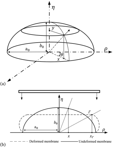
The fingertip is assumed as an ellipsoid membrane that is compressed vertically and quasi-statically by a flat, rigid, smooth plate from the top as shown in Fig. 1. The membrane is modelled as an axisymmetric, ellipsoid membrane with rigid fixed support underneath and filled with incompressible, inviscid fluid. The membrane is fitted into the cylindrical coordinates (x,y,θ) to describe the shape in its undeformed state. The centroid of the ellipsoid membrane is located at the origin with a major principal axis length a0 on the x axis and the minor principal axis length b0 on the y axis. The second cylindrical coordinates (ρ,η,θ) are used for compressed ellipsoid membranes. The xΓ denotes the value of x corresponding to the boundary Γ between the contact and free inflation regions. Elastic materials that can be fitted by a hyperelastic model, e.g., the Mooney–Rivlin model, Yeoh, or neo-Hookean model, are compatible with our model. In general, compatible materials would need to satisfy a number of criteria such as: it can be assumed that the material is incompressible, capable of large deformations and able to return to its initial state.
| W = C1(I1 − 3) + C2(I2 − 3), | (1) |
 | (2) |
 | (3) |
 obtained by ellipse standard equation
  . Throughout the paper, subscripts 1 and 2 indicate the variates in meridian and circumferential direction, respectively. The prime in the equations denotes the derivatives with respect to horizontal position x.
The principal stretch ratio λ1 is in meridian direction subscripts 1 and λ2 is in circumferential direction with subscripts 2, defined as the ratio between the undeformed lengths of an infinitesimal arc element and the deformed lengths, are:
 | (4) |
 | (5) |
 | (6) |
 | (7) |
 | (8) |
 . By substituting equations eqn (4), (7) and (8) into eqn (5), it is possible to obtain the equation set (λ1,λ2,ω), which are:
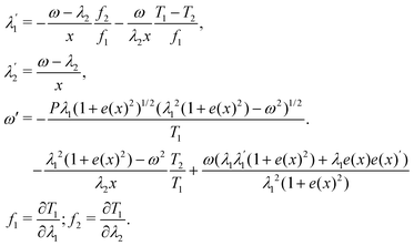 | (9) |
 | (10) |
 | (11) |
| η′ = 0, (x < xΓ). | (12) |
Therefore, the principal stretch in the contact region is
 | (13) |
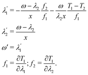 | (14) |
| Fc = AcPc = πxΓ2Pc, | (15) |
 | (16) |
 | (17) |
 | (18) |
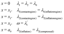 | (19) |
![[small eta, Greek, circumflex]](https://www.rsc.org/images/entities/i_char_e108.gif) − b0. The inflated membrane can then be compressed, with a maximum indentation depth of
− b0. The inflated membrane can then be compressed, with a maximum indentation depth of ![[H with combining macron]](https://www.rsc.org/images/entities/i_char_0048_0304.gif) max = Ĥinf.
max = Ĥinf.
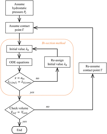
• Inflation: the membrane is first inflated with pressure P0 to the desired dimension with initial conditions λ1 = λ2 = λi = ω at the pole of the ellipsoid membrane (x = 0). The bisection method is applied to find the initial values λi that satisfy the condition ω = 0 at x = a0 and record λ2(inflation). This condition shows that the membrane is still an ellipse shape with a perpendicular tangent at x = a0. Once the dimension and shape of the ellipsoid membrane are determined, the volume of the inflated membrane Vinf is calculated using eqn (11).
• Compression: the second step requires assuming a liquid pressure Pc and contact point xΓ for the compressed ellipsoid. According to the initial condition λ1 = λ2 = λ0, apply the bisection method to find the λ0 that satisfies the second boundary conditions as shown in Fig. 2, which is the λ2(inflation) = λ2(contact) at x = a0. The volume of the compressed ellipsoid Vcom is then calculated by eqn (17) to check if the volume is equal to the inflated volume Vinf. If it is not equal, re-assume a contact boundary xΓ then repeat the previous calculation until the results satisfy all the restrictions and conditions shown in eqn (19).
Both steps are solved using the Runge Kutta method in Matlab 2021 with a tolerance of 10−2%; the solution is usually obtained in less than 20 iterations.
3.2 Feedback actuator model
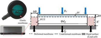
The round membrane on the feedback actuator has diameter ∅df; it is flat and elastic with thickness h0. The membrane is pressurised with Pc from the ellipsoid compression. Fig. 3 shows the configuration for membrane pressurisation. The elastic material of the membrane is incompressible, resulting in a Poisson's ratio (ν) of 0.5 and causing the deformation on top (the blue area in Fig. 3) to expand evenly on the side (the red area in Fig. 3) to keep the total volume at the same level. Assuming the contact between the membrane and rigid surface is frictionless, there are no shear forces on the membrane during the pressurisation. The Young's modulus E is defined as E = 6(1 + α)C1 as related by the Mooney–Rivlin model. The increased diameter of the contact area is: | (20) |
![[d with combining macron]](https://www.rsc.org/images/entities/i_char_0064_0304.gif) f in the contact area, the force output under the membrane is the function of df, Pc and E defined as:
f in the contact area, the force output under the membrane is the function of df, Pc and E defined as: | (21) |
4 Experiments: characterisation of the haptic feedback system
4.1 Introduction of the haptic feedback system
In our previous study, a purely hydraulic driven haptic feedback system was created with a polyjet 3D printer (Stratasys Objet500 Connex3).7 On the one hand, a soft elastic membrane shapes the outer surface of a rigid fingertip with an inner cavity. In this paper, the fingertip sensor is approximated by an ellipsoid membrane of 1 mm thickness inspired by the average size of a human index fingertip.34 The authors analysed the geometric dimensions of the index fingertip of 20 adults resulting in the measurements of 14 mm in height and 17 mm in width. On the other hand, a second elastic membrane is used for the base of the feedback actuator. A rigid housing with a cylindrical cavity is affixed on top of the elastic membrane. Water is used as the fluid medium inside the two cavities as well as the connecting hose. When forces are applied to the fingertip sensor, fluidic pressure inside the system acts on the membrane of the feedback actuator resulting in mechano-tactile sensation.4.2 Experimental protocol
This experiment was carried out to verify the results from the analytical model, which demonstrates the relationship between pressure, indentation and reaction force. The ellipsoid membrane was indented 3 mm at a perpendicular direction at a speed of 0.1 mm s−1, to minimised the effect of hysteresis. Related data of loading test, including pressure, indentation, the reaction force on the ellipsoid membrane and the force at the feedback actuator, is recorded by hardware sensors. Each trial was repeated five times, and the average across the trials was reported.4.3 Experimental setup
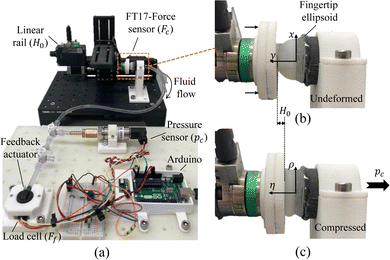
The experimental workbench was constructed as shown in Fig. 4. The setup consists of a liner rail (Zaber X LSM100A) with 0.05 mm sensitivity, a 3-axis force sensor (IIT FT17) with 0.318 mN sensitivity, a pressure sensor (OMEGA PXM 319001G) with 0.05 kPa sensitivity and a load cell (Honeywell FSA XX001RC4C5) with 0.22 mN sensitivity. The liner rail controls the indentation depth H0, and the fixed force sensor records the reaction force Fc on the ellipsoid membrane. The pressure transducer records the hydrostatic pressure Pc change during the test. The feedback actuator was fixed into the socket, and the elastic membrane was in contact with the load cell to measure the blocked force Ff from the feedback actuator. The elastic finger ellipsoid and elastic membrane in feedback actuator is made from Agilus30 by a polyjet 3D printer (Stratasys Objet500 Connex3) with 0.1 mm accuracy. The hyperelastic property of Agilus30 is determined by the strain–stress curve, and the constant of Mooney–Rivlin model is C1 = 160![[thin space (1/6-em)]](https://www.rsc.org/images/entities/char_2009.gif) 355 Pa and C2 = 46
355 Pa and C2 = 46![[thin space (1/6-em)]](https://www.rsc.org/images/entities/char_2009.gif) 559 Pa.38 The entire system was immersed into water completely including the pipe and degassed by a vacuum pump to remove the air bubble inside of the closed cavity.
559 Pa.38 The entire system was immersed into water completely including the pipe and degassed by a vacuum pump to remove the air bubble inside of the closed cavity.
5 Results and discussion
5.1 Experimental and computational results
Fig. 5(a) and (b) illustrate the reaction force Fcversus indentation H0 and the hydrostatic pressure Pcversus H0, respectively. Both Fc and Pc show an identical non-linear increasing behaviour. The reaction force Fc is sensitive with lower indentation depth, which from 0 N to 1.6 N accounts for 50% of total indentation (0 mm to 1.5 mm). After 1.5 mm, the compression force Fc and hydrostatic pressure Pc rises non-linearly with further compression. The stiffness of the membrane shows non-linear increasing behaviour in response, as the same indentation step causes a larger increase in Fc and Pc. For an indentation smaller than 2.4 mm, the results from the model lay within the mean standard error (MSE) of the experimental data; the MSE is 0.92 for Fc, 0.584 for Pc and 0.052 for Ac. Meanwhile, increasing the initial stretch λ0 results in the membrane stiffening at all indentation levels, especially after 1.2 mm where the deviation from the linear relationship behaves in a non-linear manner (Fig. 5(a)). If the initial stretch λ0 is assumed to be 2.3, the model results fit best to the average of the experimental data at all indentation levels. | ||
| Fig. 5 Comparison between the model results and the experimental data. (a) Reaction force Fc on the membrane versus indentation H0. Reaction force Fc from the model was calculated by eqn (21) (b) hydrostatic pressure Pcversus indentation H0. Hydrostatic pressure Pc in the model was assumed during the calculation of eqn (9) to meet boundary conditions. (c) Contact area Acversus reaction force Fc on the membrane. Contact area Ac from the model is calculated by Ac = πxΓ2. | ||
The contact area is a flat surface on top of the membrane that reflects the configuration of deformation in the compression stage. The contact area Ac calculated using Fc and Pc, i.e. (Ac = Fc/Pc). Fig. 5(c) shows that Ac increases rapidly at the initial compression stage, with 60% of the total contact area achieved at 4–5 N.
Fig. 6(a) shows the shape change of the membrane in the inflation stage based on the results from the model. At the initial inflation stage, the height rapidly increases, which in turn increases the aspect ratio (τ = b0/a0) as shown in Fig. 6(a). After the initial shape change, the entire membrane expands evenly by applying a higher pressure level with a larger initial stretch ratio λ0. Fig. 6(b) and (c) illustrate the stress resultant Ti and the stretch ratio λiversus the horizontal position x. Inflation leads to nonuniform distribution of stress and strain. The maximum stress resultant T1 and stretch ratio λ1 in the circumferential direction occurs at the pole of the ellipsoid membrane (x = 0) and decreases towards the edge of the membrane (x = a0). The stress resultant and the stretch ratio in the meridian direction demonstrate an opposite behaviour compared to the circumferential direction. The transition from initial inflation to entire expansion depends on the material property and aspect ratio. In order to inflate the ellipsoid membrane from a0 = 4.5 mm,τ = 0.6 to ρ = 9 mm with τ = 0.78. In this instance, it happens at λ0 = 2.3 and Pi = 2.1 kPa with Agilus30. The inflation determines the lower bound of pressure in compression.
 | ||
| Fig. 6 Inflated membrane. At the initial inflation stage, the height increases rapidly, causing the aspect ratio τ to likewise increases. With higher pressure inflation, the entire membrane inflates evenly. (a) Cross-section view of the inflated membranes with different initial stretch ratios λ0 calculated by eqn (10). (b) Principle stretch ratios λ1 and λ2 of an ellipsoid membrane calculated by eqn (9). (c) Resultant stress in the circumferential and meridian directions calculated by eqn (7). | ||
Under compression, the membrane is flattened on the top by a rigid plate while the free inflation region bulges around the membrane to keep the inside volume constant as shown in Fig. 7(a). Further compression results in higher hydrostatic pressure. Meanwhile, the stress resultant and the stretch ratio in the meridian and circumferential direction increase at all levels in response.
 | ||
| Fig. 7 Compressed membrane. With higher indentation, the membrane is flattened on the top and inflated on the side. (a) Profiles of compressed membranes with different indentation and pressure. The position of the membrane is calculated by eqn (16). (b) Principle stretch ratios λ1 and λ2 of an ellipsoid membrane calculated by eqn (14). (c) Resultant stress in the circumferential and meridian direction calculated by eqn (7). | ||
The points encircled with red in Fig. 7(b) and (c) are the contact boundary ![[x with combining tilde]](https://www.rsc.org/images/entities/i_char_0078_0303.gif) Γ, where
Γ, where ![[x with combining tilde]](https://www.rsc.org/images/entities/i_char_0078_0303.gif) Γ = xΓ/a0. From x = 0 to x = xΓ, the stretch ratio (λ1,λ2) and the stress resultant (T1,T2) remains similar to their initial values but briefly decrease. In the free inflation region (xΓ < x < a0), the stretch ratio and the stress resultant change their behaviour by increasing in the meridian direction and decreasing in the circumferential direction. In this instance, the edge of the ellipsoid membrane is constrained by satisfying λ2(inflation) = λ2(compressed) = 2 at (x = a0).
Γ = xΓ/a0. From x = 0 to x = xΓ, the stretch ratio (λ1,λ2) and the stress resultant (T1,T2) remains similar to their initial values but briefly decrease. In the free inflation region (xΓ < x < a0), the stretch ratio and the stress resultant change their behaviour by increasing in the meridian direction and decreasing in the circumferential direction. In this instance, the edge of the ellipsoid membrane is constrained by satisfying λ2(inflation) = λ2(compressed) = 2 at (x = a0).
After verifying the analytical model of an ellipse compression, the valve is open and forms a closed cavity with the ellipsoid membrane and feedback actuator. Increased hydrostatic pressure can transmit to the ∅9 mm membrane of the feedback actuator and pressurise the membrane to generate the blocked force. The hydrostatic pressure Pc and force from the feedback actuator Ff show a linear relationship in the experimental data and model results (Fig. 8). Overall, the model results show a higher force response than the experimental data; the model result reach a maximum force of 1.98 N at pressure 17.9 kPa while feedback force in the experimental data is 1.68 N at same pressure.
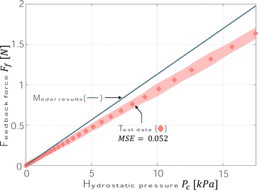 | ||
| Fig. 8 Linear relationships between the output force (calculated by eqn (21)) at the feedback actuator and the hydrostatic pressure for each feedback actuator membrane. | ||
5.2 Discussion
As we assumed that the undeformed status in the experimental condition is equivalent to the inflated membrane in the analytical model, which is different to the experimental setup with no inflation (hence, the stress on the membrane is zero before compression), the initial inflation pressure P0 has been considered in the compressed pressure Pc to compensate for the pressure difference in the pre-compression condition between the model and experiment. Our modelling results with minimum inflation pressure P0 should be identical to the experimental condition, which has no inflation at the beginning (see Fig. 5). However, the force and pressure curve is lower than the experimental results (P0 = 2.0 kPa, λ0 = 2.2). This might be due to the negligible friction between the membrane and rigid plate. The membrane stiffens with a higher inflation pressure P0 and stretch ratio λ0, which results in a higher reaction force and pressure at the same indentation depth. By stiffening the membrane, it compensates for the friction disturbance and the difference between the ideal and practical conditions. In fact, the force and pressure curve shows a good agreement with the experimental results (P0 = 2.1 kPa, λ0 = 2.3).After the membrane is inflated to the desired shape, the volume and the edge of the membrane is constrained by converging λ2(inflation) = λ2(contact) at x = a0 as it can be seen in Fig. 7(a) and (b). Within the contact region x ∈ (0,xΓ), the stretch of the membrane is isotropic, i.e. ‖λ1 − λ2‖ < 10−2. As the membrane is compressed further and the contact region increases, the zone of isotropic stretching likewise increases. Where x ∈ (xΓ,a0), the stretch in the meridian and circumferential directions are anisotropic. Meridian stress on the symmetry plane constrains the indention depth of the membrane. Moreover, circumferential stress constrains the expansion of the membrane in the vertical view.
As the indentation depth H0 increases close to ![[H with combining macron]](https://www.rsc.org/images/entities/i_char_0048_0304.gif) max, the initial stretch ratio λ0 gradually increases. The stress resultant Ti likewise increases with each compression step as it is evident from (Fig. 7(b) and (c)). The membrane resists further compression by acting with higher stiffness of the material on all membranes with a higher stretch ratio and stress. The maximum indentation depth
max, the initial stretch ratio λ0 gradually increases. The stress resultant Ti likewise increases with each compression step as it is evident from (Fig. 7(b) and (c)). The membrane resists further compression by acting with higher stiffness of the material on all membranes with a higher stretch ratio and stress. The maximum indentation depth ![[H with combining macron]](https://www.rsc.org/images/entities/i_char_0048_0304.gif) max is determined by the inflated height Ĥinf and original height b0, which means the inflation stage provides the lower bound of the indentation.
max is determined by the inflated height Ĥinf and original height b0, which means the inflation stage provides the lower bound of the indentation.
During the inflation stage, slight pressure might lead to a significant expansion in the geometry due to lack of constraints at the edge of the membrane for the initial inflation. The initial dimension of the ellipsoid membrane a0 and b0 with the inflation condition P0 and λ0 are varied and have different combinations of values but can yield the same desired dimension. As a0 and b0 decrease with increasing inflation pressure P0, Ĥinf increases as well as the maximum indentation depth ![[H with combining macron]](https://www.rsc.org/images/entities/i_char_0048_0304.gif) max evident by a good agreement with the experiment data in Fig. 5 at higher inflation pressure values P0. Hence, the combination with a slightly larger inflation height Ĥinf at higher inflation pressure P0 has been selected and compared with the indentation depth
max evident by a good agreement with the experiment data in Fig. 5 at higher inflation pressure values P0. Hence, the combination with a slightly larger inflation height Ĥinf at higher inflation pressure P0 has been selected and compared with the indentation depth ![[H with combining macron]](https://www.rsc.org/images/entities/i_char_0048_0304.gif) max. The initial inflation produces a nonuniform stretch and stress on the membrane as shown in Fig. 6(b) and (c). As the inflation pressure increases, the deviation level of stress and stretch ratio in the meridian and circumferential direction increases. Hence, the ellipsoid membrane shows anisotropy in the inflated states.
max. The initial inflation produces a nonuniform stretch and stress on the membrane as shown in Fig. 6(b) and (c). As the inflation pressure increases, the deviation level of stress and stretch ratio in the meridian and circumferential direction increases. Hence, the ellipsoid membrane shows anisotropy in the inflated states.
It is worth noting that we established a number of assumptions for our analytical model. In particular, the assumptions, that the model considers the compression of a pre-inflated membrane and that the thickness of the membrane remains unchanged, might add errors to our modelling formulation. In our paper, the membrane of the fingertip shows an anisotropic behaviour in its inflated state. In the experiments, however, the membrane is unstretched. When the inflated membrane is compressed in the computational model, the offset of the stress caused by the initial inflation remains. Hence, the results might show higher stress levels compared to the experimental results. On the other side, the change of thickness during the deformation is neglected because the thickness of the membrane is significantly smaller than the width and height of the fingertip membrane. A limitation might occur if membranes are considered that have larger thicknesses.
During the experimental procedure, the feedback actuator is mounted on a socket. The deflated membrane is then in full contact with the load cell restricting free inflation and generating blocked forces. The membrane exhibits a change in volume. Volume change ΔV (Fig. 3) can be calculated by ΔV = dfΔh. Under 17.935 kPa, the volume change ΔV is 1.38 mm3, which means the total volume change of the flat membrane being pressurised by Pc is 0.432% of the volume of the inflated membrane Vinf. Hence, the volume change of the ellipsoid membrane, in which the fluid flows to the feedback actuator, is negligible.
The maximum deviation between the experimental and computational results for the feedback actuator is about 18.56% at a pressure value of 17.9 kPa in Fig. 8. It can be observed that the deviation proportionally increases with the hydrostatic pressure. The reasons for this discrepancy might be manifold. One reason might be due to the increase in friction between the surface of the elastic membrane and the load cell preventing the membrane to stretch. This behaviour is neglected in our computational model of the feedback actuator. Another reason might relate to the manufacturing process of the actuator. The membrane is fixed onto the solid structure by the multi-material 3D printer by Stratasys. The bond between these two materials might vary in strength.
The computational results of our analytical model are compared to results reported in the literature as summarised in Table 1. The table shows the calculated or measured reaction force Fc at H0 = 0.5 mm and 2 mm indentation. As a reference, the experimental results of force-indentation of a fingertip were reported by Serina.39 Then, the computational results of an FEA36 are listed in the table as well as the results of our model using the material constants of skin tissue (C1 = 13![[thin space (1/6-em)]](https://www.rsc.org/images/entities/char_2009.gif) 400 Pa, C2 = 29
400 Pa, C2 = 29![[thin space (1/6-em)]](https://www.rsc.org/images/entities/char_2009.gif) 500 Pa)34 on the one hand and the material contestants of Aglius30 on the other hand. Maximum errors are calculated with respect to the experimental results of a fingertip compression. When considering the constants of Aglius30 material, the maximum error is similar to the results of the FEA. The error is lower (14.7%) for results taking the material constants of human skin tissue as input.
500 Pa)34 on the one hand and the material contestants of Aglius30 on the other hand. Maximum errors are calculated with respect to the experimental results of a fingertip compression. When considering the constants of Aglius30 material, the maximum error is similar to the results of the FEA. The error is lower (14.7%) for results taking the material constants of human skin tissue as input.
| 0.5 mm | 2 mm | ε max | |
|---|---|---|---|
| a ε max: maximum deviation error compared with experimental results from the fingertip compression. | |||
| Exp. results of fingertip compression39 | 0.32 N | 1.94 N | — |
| FEA results36 | 0.36 N | 2.09 N | 19.3%(0.5 mm) |
| Analytical (Skin) | 0.27 N | 1.99 N | 14.7%(0.5 mm) |
| Analytical (Agilus30) | 0.38 N | 2.11 N | 18.7%(0.5 mm) |
6 Conclusions
This paper derived and validated an analytical compression model for both an ellipsoid and a flat membrane as well as validated the models based on experimental data. The model is capable to capture the ellipsoid membrane's non-linear force response under compression in line with experimental data (Fig. 5). In our approach, we used the Cartesian coordinate to obtain the ODE equations, which differs from the use of a polar coordinate by ref. 34 resulting in a simplified set of ODEs. By inserting the dimension of the ellipsoid membrane (a0,b0), material property (C1,C2) and thickness (h0), the inflation and compression can be solved, considering the hydrostatic pressure Pc, reaction force Fc and contact area Ac with membrane shape deformation as illustrated in Fig. 5. In our case study, the elastic ellipsoid membrane has a major axis length of 9 mm with a minor axis length of 7 mm similar to the average size of a natural human fingertip producing similar non-linear force-indentation relationship of the human fingertip with a semblable force level of 0–4 N at 0–2 mm indentation.39Our theoretical computations can predict the inflated and compressed states of the ellipsoid membrane. Hence, by designing the haptic feedback system for different sizes of fingertip membranes and feedback actuators with different elastic materials, the model can predict the performance of the haptic feedback system and optimise the design to replicate the force-indentation curve. The deformation theory for the ellipsoid membrane is not only limited to modelling the fingertip compression but also has the potential to model inflation and compression of an ellipsoid membrane in generic cases.
Author contributions
Ge Shi: Methodology, software, hardware setup, formal analysis, investigation, data curation, writing – original draft, visualization. Azadeh Shariati: investigation, writing – review & editing. Ian Eames: methodology, software, formal analysis, writing – review & editing. Helge A. Wurdemann: conceptualization, methodology, resources, supervision, writing – review & editing, visualization, project administration, funding acquisition.Conflicts of interest
There are no conflicts to declare.Acknowledgements
This research has been supported by the Grand Challenges Small Grant received from UCL Grand Challenges, the Engineering and Physical Sciences Research Council (grant number: EP/V01062X/1) and UCL-IIT Delhi Seed Funding 2020-21 received from UCL Global Engagement.Notes and references
- J. S. Schofield, K. R. Evans, J. P. Carey and J. S. Hebert, Applications of sensory feedback in motorized upper extremity prosthesis: a review, Expert Rev. Med. Devices, 2014, 11, 499–511 CrossRef CAS PubMed.
- P. Svensson, U. Wijk, A. Björkman and C. Antfolk, A review of invasive and non-invasive sensory feedback in upper limb prostheses, Expert Rev. Med. Devices, 2017, 14, 439–447 CrossRef CAS PubMed.
- D. S. Childress, Closed-loop control in prosthetic systems: historical perspective, Ann. Biomed. Eng., 1980, 8, 293–303 CrossRef CAS PubMed.
- J. J. E. Conzelman, H. B. Ellis and C. W. O'brien, Prosthetic device sensory attachment, US Pat., 2656545, 1953 Search PubMed.
- C. Antfolk, A. Björkman, S.-O. Frank, F. Sebelius, G. Lundborg and B. Rosen, Sensory feedback from a prosthetic hand based on air-mediated pressure from the hand to the forearm skin, J. Rehabilitation Med., 2012, 44, 702–707 CrossRef PubMed.
- M. F. Simons, K. M. Digumarti, N. H. Le, H.-Y. Chen, S. C. Carreira, N. S. Zaghloul, R. S. Diteesawat, M. Garrad, A. T. Conn and C. Kent, et al., B: ionic glove: a soft smart wearable sensory feedback device for upper limb robotic prostheses, IEEE Rob. Automation Lett., 2021, 6, 3311–3316 Search PubMed.
- G. Shi, A. Palombi, Z. Lim, A. Astolfi, A. Burani, S. Campagnini, F. G. Loizzo, M. L. Preti, A. M. Vargas and E. Peperoni, et al., Fluidic haptic interface for mechano-tactile feedback, IEEE Trans. Haptics, 2020, 13, 204–210 Search PubMed.
- B. A. Trimmer, New challenges in biorobotics: incorporating soft tissue into control systems, Appl. Bionics and Biomechanics, 2008, 5, 119–126 CrossRef.
- N. Herzig, J. Jones, E. Perez-Guagnelli and D. D. Damian, Model and validation of a highly extensible and tough actuator based on a ballooning membrane, 2021 IEEE International Conference on Robotics and Automation (ICRA), 2021, 11961–11967 Search PubMed.
- J. Barreiros, I. Karakurt, P. Agarwal, T. Agcayazi, S. Reese, K. Healy and Y. Menguc, Self-sensing Elastomeric Membrane for Haptic Bubble Arrray., 2020 3rd IEEE International Conference on Soft Robotics (RoboSoft), 229–236 Search PubMed.
- S. Sareh, A. Jiang, A. Faragasso, Y. Noh, T. Nanayakkara, P. Dasgupta, L. D. Seneviratne, H. A. Wurdemann and K. Althoefer, Bio-inspired tactile sensor sleeve for surgical soft manipulators, 2014 IEEE International Conference on Robotics and Automation (ICRA), 1454–1459 Search PubMed.
- H. A. Sonar, A. P. Gerratt, S. P. Lacour and J. Paik, Closed-loop haptic feedback control using a self-sensing soft pneumatic actuator skin, Soft Robot., 2020, 7, 22–29 CrossRef PubMed.
- F. Veiga, B. Edin and J. Peters, Grip stabilization through independent finger tactile feedback control, Sensors, 2020, 20, 1748 CrossRef PubMed.
- O. S. Osman, J. L. Selway, M. A. Kepczyńska, C. J. Stocker, J. F. O’Dowd, M. A. Cawthorne, J. R. Arch, S. Jassim and K. Langlands, A novel automated image analysis method for accurate adipocyte quantification, Adipocyte, 2013, 2, 160–164 CrossRef CAS PubMed.
- D. R. Grimes and F. J. Currell, Oxygen diffusion in ellipsoidal tumour spheroids, J. R. Soc., Interface, 2018, 15, 20180256 CrossRef PubMed.
- A. Stanzione, A. Ponsiglione, G. A. Di Fiore, S. G. Picchi, M. Di Stasi, F. Verde, M. Petretta, M. Imbriaco and R. Cuocolo, Prostate volume estimation on MRI: accuracy and effects of ellipsoid and bullet-shaped measurements on PSA density, Acad. Radiol., 2021, 28, e219–e226 CrossRef PubMed.
- C. Pozrikidis, Modeling and simulation of capsules and biological cells, Chapman and Hall/CRC, 2003 Search PubMed.
- M. W. Keller and N. R. Sottos, Mechanical properties of microcapsules used in a self-healing polymer, Exp. Mech., 2006, 46, 725–733 CrossRef CAS.
- W.-H. Hsu, Y.-H. Chien and H.-Y. Tsai, Experimental and Modeling Analysis of the Cell-Wall Fracture of Nannochloropsis Oculata, J. Mech., 2020, 36, 789–797 CrossRef.
- C. L. Eccles, R. Patel, A. K. Simeonov, G. Lockwood, M. Haider and L. A. Dawson, Comparison of liver tumor motion with and without abdominal compression using cine-magnetic resonance imaging, Int. J. Radiat. Oncol., Biol., Phys., 2011, 79, 602–608 CrossRef PubMed.
- M. Mooney, A theory of large elastic deformation, J. Appl. Phys., 1940, 11, 582–592 CrossRef.
- R. S. Rivlin, Large elastic deformations of isotropic materials IV. Further developments of the general theory, Philos. Trans. R. Soc., A, 1948, 241, 379–397 CrossRef.
- J. E. Adkins and R. S. Rivlin, Large elastic deformations of isotropic materials IX. The deformation of thin shells, Philos. Trans. R. Soc., A, 1952, 244, 505–531 CrossRef.
- W. Yang and W. Feng, On axisymmetrical deformations of nonlinear membranes, J. Appl. Mech., 1970, 37, 1002–1011 CrossRef.
- W. Feng and P. Huang, On the inflation of a plane nonlinear membrane, J. Appl. Mech., 1974, 41, 767–771 CrossRef.
- Y. Bouremel, I. Eames, S. Madaan, S. Brocchini and P. T. Khaw, Compression of pressurised elastic pockets, Int. J. Non Linear Mech., 2018, 107, 10–15 CrossRef.
- W. Feng and W.-H. Yang, On the contact problem of an inflated spherical nonlinear membrane, J. Appl. Mech., 1973, 40, 209–214 CrossRef.
- G. Sun and Z. Zhang, Mechanical strength of microcapsules made of different wall materials, Int. J. Pharm., 2002, 242, 307–311 CrossRef CAS PubMed.
- S. Mettu, Q. Ye, M. Zhou, R. Dagastine and M. Ashokkumar, Ultrasonically synthesized organic liquid-filled chitosan microcapsules: part 2: characterization using AFM (atomic force microscopy) and combined AFM-confocal laser scanning fluorescence microscopy, Soft Matter, 2018, 14, 3192–3201 RSC.
- D. Margolis, J. Tylee and D. Hrovat, Heave mode dynamics of a tracked air cushion vehicle with semiactive airbag secondary suspension, J. Dyn. Syst., Meas., Control, 1975, 97, 399–407 CrossRef.
- X. Yang, L. Yu and R. Long, Contact mechanics of inflated circular membrane under large deformation: analytical solutions, Int. J. Solids Struct., 2021, 233, 111222 CrossRef.
- G. Tamadapu and A. DasGupta, Finite inflation analysis of a hyperelastic toroidal membrane of initially circular cross-section, Int. J. Non Linear Mech., 2013, 49, 31–39 CrossRef.
- X. Li and D. Steigmann, Finite deformation of a pressurized toroidal membrane, Int. J. Non Linear Mech., 1995, 30, 583–595 CrossRef.
- E. R. Serina, E. Mockensturm, C. Mote Jr and D. Rempel, A structural model of the forced compression of the fingertip pulp, J. Biomech., 1998, 31, 639–646 CrossRef CAS PubMed.
- T. Inoue and S. Hirai, Elastic model of deformable fingertip for soft-fingered manipulation, IEEE Trans. Robot., 2006, 22, 1273–1279 Search PubMed.
- J. Z. Wu, R. G. Dong, S. Rakheja and A. Schopper, Simulation of mechanical responses of fingertip to dynamic loading, Med. Eng. Phys., 2002, 24, 253–264 CrossRef CAS PubMed.
- J. Z. Wu, R. G. Dong, S. Rakheja, A. Schopper and W. Smutz, A structural fingertip model for simulating of the biomechanics of tactile sensation, Med. Eng. Phys., 2004, 26, 165–175 CrossRef CAS PubMed.
- F. F. Abayazid and M. Ghajari, Material characterisation of additively manufactured elastomers at different strain rates and build orientations, Addit. Manuf., 2020, 33, 101160 CAS.
- E. R. Serina, C. Mote Jr and D. Rempel, Force response of the fingertip pulp to repeated compression—effects of loading rate, loading angle and anthropometry, J. Biomech., 1997, 30, 1035–1040 CrossRef CAS PubMed.
| This journal is © The Royal Society of Chemistry 2022 |

