 Open Access Article
Creative Commons Attribution 3.0 Unported Licence
Tuning photoelectrochemical performance of poly(3-hexylthiophene) electrodes via surface structuring
Renbo
Wei
ab,
Maciej
Gryszel
 bc,
Ludovico
Migliaccio
bc and
Eric Daniel
Głowacki
 *bcd
*bcd
aSchool of Chemical Engineering, Northwest University, Xi’an 710069, Shaanxi, P. R. China
bLaboratory of Organic Electronics, Campus Norrköping, Linköping University, SE-60174, Norrköping, Sweden. E-mail: eric.glowacki@liu.se
cWallenberg Centre for Molecular Medicine, Linköping University, SE-58185, Linköping, Sweden
dWarsaw University of Technology, Faculty of Chemistry, 00-664 Warsaw, Poland
First published on 22nd June 2020
Abstract
Organic semiconductors are gaining increasing attention as promising active materials in aqueous electrochemical and photoelectrochemical applications. Controlling the semiconductor/electrolyte interface is a critical aspect. The aim of this work is to increase the electrochemical surface area of an archetypical polymeric semiconductor, poly(3-hexylthiophene), P3HT. Here we use a technique of blending with polystyrene, phase separation, followed by selective removal of polystyrene to obtain various nano/microstructures of P3HT. We evaluate how three-dimensional structuring of P3HT affects electrochemical capacitance, photovoltage generation, and photoelectrochemical currents. The aqueous wettability of the exposed surface is critical, and it can be significantly modified by employing oxygen plasma treatment. Structured and plasma-hydrophilized P3HT samples demonstrate higher photoelectrochemical currents for the oxygen reduction reaction. We find that regardless of structuring and photocurrent performance, the oxygen reduction on P3HT always proceeds to produce H2O2 with 90%+ faradaic efficiency. The results of our efforts are demonstrations of how to tune and to increase both electrochemical capacitive and faradaic behavior of P3HT layers. Our findings indicate some limitations imposed by the P3HT itself, including low photovoltages and photochemical bleaching. Overall, these findings answer several open questions in the field of P3HT photoelectrochemical interfaces, and provide some general guidelines that can be applied to other organic semiconducting materials.
Introduction
The question of effective electrochemical surface is of fundamental importance for photoelectrocatalytic processes occurring on semiconductor electrodes.1,2 While for many inorganic semiconductors the concept of surface structuring to increase photoelectrochemical performance is established with myriad examples,1,3,4 organic semiconductor-based electrodes have been little studied in this context. With organic semiconductor electrodes emerging as soft, ultrathin, and biocompatible alternatives to traditional materials for biomedical and bioelectronics applications,5,6 working towards maximizing effective electrochemical surface becomes increasingly relevant. This especially applies for the growing applications of organic semiconductor photoelectrode biointerfaces for photostimulation of excitable tissues7,8 and modulating cellular physiology.9–12 In this work, we endeavor to nano/microstructure the surface of the best-known example material in the aforementioned studies: poly(3-hexylthiophene), P3HT. P3HT was employed widely in organic photovoltaics,13 organic thin film transistors, and increasingly in bioelectronics applications.14 In bioelectronics, P3HT first emerged as a representative p-type material in electrolyte-gated transistors.15 P3HT can also be electrochemically-doped, modulating its conductivity.16 Recently, P3HT as a highly-efficient light absorber, has gained attention for photoactivated biointerfaces,17 alongside other organic semiconducting materials reported for this purpose.9,18 P3HT can act as a photothermal material, effectively converting visible light irradiation into heat.8 P3HT can also generate photoelectrochemical currents, driving faradaic reactions and altering the (electro)physiology of cells.19,20 Photoinduced physiological effects mediated by P3HT have been observed in a number of in vitro8,10,11 and in vivo21,22 models. P3HT can be conveniently coated from solution onto arbitrary substrates, but is also useful as an aqueous dispersion of nanoparticles.23 Structured pillars of P3HT can also make unique interfaces with cells.24 In all these applications, the fundamental questions hinge around electrochemical and photoelectrochemical phenomena, and how to regulate them. It is widely recognized that the primary photochemical process occurring at the surface of P3HT under irradiation in water is oxygen reduction,25 with hydrogen peroxide implicated as the final product.26 The effects of photogenerated reactive oxygen species is an area of substantial interest in biophysics.11,27 On the other hand, the possibility of hydrogen evolution via proton reduction on P3HT has been found to be very inefficient (in the absence of a cocatalyst) and occurs only in trace amounts compared to the dominant oxygen reduction reaction.25,28Herein, we have addressed the question of structuring P3HT for the purpose of tuning and enhancing its photoelectrochemical properties, and trying to understand the factors at play. The basic starting hypothesis is that by structuring the P3HT, a higher (photo)electrochemical surface area will emerge. An inspiration for this approach is bulk heterojunction solar cells, where the role of donor/acceptor phase separation is recognized to be one of the most critical parameters in supporting efficient photocharge generation.29 Many methods for structuring P3HT have been explored, in the context of photovoltaics, as well as bioelectronic interfaces.24 The influence of nano/microstructure and crystallinity on electrochemical transfer reactions with P3HT (primarily nonaqueous) has been studied in detail by Ratcliff and coworkers,16,30–32 and the work herein aims to build on that in the context of aqueous photoelectrochemistry.
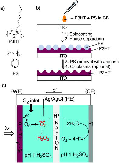
Here we have adapted a simple strategy that has been established in the literature,32–35 that of phase-separation templating. A constant quantity of P3HT is dissolved in solution together with varying amounts of polystyrene, PS (Fig. 1a). The solution is cast, and following evaporation of the solvent, the two polymers phase separate. By then applying a solvent which dissolves PS selectively, a templated structure of P3HT is left behind (Fig. 1b). Here we have tested a reliable series of different micro/nanostructured P3HT films which can be made on an underlying semitransparent electrode. We characterized the structured P3HT films, versus a planar reference, from the point of view of morphology, wettability, electrochemical capacitance, photovoltage generation, and finally photofaradaic oxygen reduction performance (Fig. 1c).
Results and discussion
Three-dimensional morphologies of P3HT
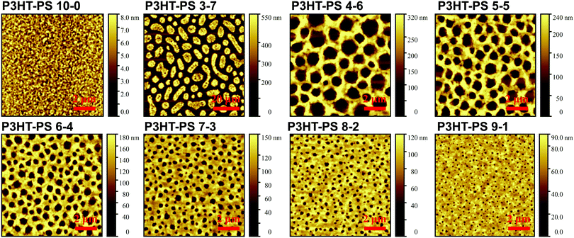
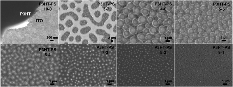
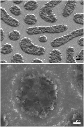
P3HT was dissolved in chlorobenzene and PS was added at various ratios. The P3HT + PS solution was then spin coated onto octyltriethoxysilane (OTS) modified indium tin oxide (ITO) substrates. The OTS modification was found to be crucial to prevent unwanted delamination during prolonged electrochemistry experiments in aqueous electrolytes. Otherwise, water can wet the ITO through the pores in the P3HT and can “lift up” the P3HT films. After spin-coating and solvent evaporation, microphase separation occurs between PS and P3HT domains in the resulting films. We found that rinsing the films in acetone overnight caused leaching out of all the PS, leaving behind a structured 3D surface of P3HT. We produced reproducible phase-separated structures by using a total of 10 mg ml−1 of dissolved P3HT material in the chlorobenzene, with varying the amount of added PS in steps (Shown in Table 1) to obtain ratios from 10–0 P3HT–PS to 3–7 P3HT–PS. AFMs showing the range of possible 3D structures for different mass ratios is presented in Fig. 2. Neat P3HT 10–0 films treated with acetone afforded a nanoscale RMS roughness of a few nanometers. The addition of PS content resulted in the formation of pores, with increasing PS loading corresponding to increased pore size and density. Once the PS content was increased such that ratio was 3–7 P3HT–PS, the 3D structure “inverted”. This ratio produces columns of P3HT with a diameter of several micrometers, and empty space between. The columns possess a finely-nanostructured surface. Scanning electron microscopy (SEM) corroborates the structures apparent in AFM, but yields additional useful information (Fig. 3 and 4). The larger micron-sized pores produced from mixing ratios of 4–6 to 8–2 P3HT–PS clearly penetrate all the way down to the underlying ITO substrate. This is apparent as the distinctive ITO crystallites can be seen at the bottom of most pores. The smaller pores present in 9–1 P3HT–PS, meanwhile, are apparently not open-ended and resemble dimples in the P3HT surface that never reach down to the underlying ITO. The structures formed from the 3–7 P3HT–PS mixing ratio are remarkable in that P3HT islands are formed with micron-scale depressions with additional nanoporous structure (Fig. 4). It should be noted that since the mass content of P3HT in each casting solution is constant, addition of PS causes the resultant structures to have a greater thickness. While a neat P3HT film has a thickness of around 48 nm (based on scanning profilometry), the structures formed from mixed layers have progressively higher thickness, with P3HT–PS 3–7 giving an effective height of 550 nm (based on AFMs shown in Fig. 2).Wettability
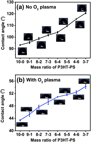
After establishing the different microstructures which were possible, the next evaluated parameter we turned our attention to was water contact angle. Aqueous wettability is a key consideration when using such semiconductor interfaces for photoelectrochemistry or bioelectronic interfaces. The measured water contact angles are plotted in Fig. 5. Increased pore size and pore density corresponds with increased contact angle, i.e. the greater the exposed P3HT surface, the more hydrophobic the sample is. This fits with the well-established principle that hydrophobic materials,36 like P3HT, when nano-microstructured, will display increased hydrophobicity. Treatment of the P3HT samples with mild O2 plasma changes the wettability significantly. The water contact angle drops by a factor of more than 2. The trend of increasing hydrophobicity with structured samples remains the same, albeit the dependence is shallower, as the contact angles vary over only a 10 degree range.Electrolytic capacitance
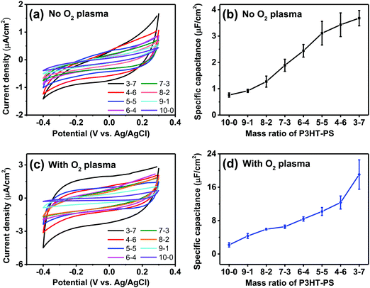
We next turned our attention to the electrochemical capacitance properties of these structured P3HT samples. We have used the cyclic voltammetry (CV) in the electrochemically-passive region to estimate the electrolytic capacitance.37 The CVs as well as calculated capacitance values are presented in Fig. 6. We observed a marked trend of increasing electrochemical capacitance accompanying increased porosity. Indeed, qualitatively the trends resemble those of contact angle shown in Fig. 5. We found that as-fabricated planar P3HT films had a capacitance of around 0.8 μF cm−2, which increases to 3 μF cm−2 following treatment with oxygen plasma. These values are in-line with what has been reported in the literature: P3HT films, characterized in the context of electrolyte-gated field effect transistors, have been measured to have electrolytic capacitance in the range of roughly 1–12 μF cm−2,38 similar to other organic films such as evaporated pentacene.39 Nevertheless, we find that there is a substantial effect of oxygen plasma increasing the electrolytic capacitance of P3HT films.Dynamic electrophotoresponse – intrinsic photovoltage and photocurrent generation
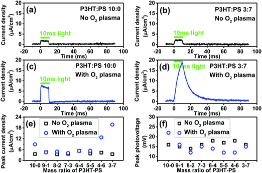
The photoelectrochemical behavior of P3HT is the most salient question we sought to evaluate here, as photoelectrochemistry is key to emerging bioelectronic applications of P3HT, as well as investigations seeking to use organic photosensitizers for catalytic reactions.28,40 In our previous works on organic photoelectrochemical neurostimulation devices, we introduced a simple technique for evaluating the dynamic photocurrent generation in thin films devices – the electrophotoresponse technique (EPR).7,41,42 Here, a thin film semiconductor is measured in short circuit conditions, between the underlying back contact, and a confined electrolyte above the semiconductor layer. The confined electrolyte forms an electrolytic contact, as it contains an ideally nonpolarizable electrode of Ag/AgCl. Square wave light pulses (pulse length of a few ms) illuminate the sample, allowing measurement of the photocharging of electrical double layers as well as possible sustained faradaic reactions. No external bias is applied to the sample. The dynamic voltage is registered on an oscilloscope. Connecting a transimpedance amplifier in series, one can measure photocurrents as well. We evaluated the P3HT samples with this configuration, using a pulsed green LED (515 nm, 50 mW cm−2). The results for photocurrents and photovoltages are plotted in Fig. 7. All samples, regardless of structure or oxygen plasma treatment, gave the same photovoltage of roughly 12–18 mV. This is the total photoinduced potential difference induced by the P3HT across the electrolyte. The low photovoltage generated by P3HT can be hypothesized to originate from a combination of sources. It is worthwhile to consider that solid-state photovoltaic diodes of the type ITO/P3HT/Al also afford roughly 20 mV of open circuit potential under illumination.43 This suggests that the voltage loss is not related to the electrochemical interface. The observation that our measured photovoltage value remains consistent despite surface structuring further indicated this is an intrinsic property of the P3HT. P3HT is an excitonic material, with exciton binding energy estimated to be around 0.9 eV.44 This likely incurs the largest voltage penalty. A further portion of the voltage loss may be resistance introduced at the ITO/P3HT interface, and recent works on P3HT photocathodes indicate that performance can be improved if a high work-function hole-sensitive interlayer is used.28 Next, effects from known hole trap levels45 in P3HT can further decrease photovoltage. Regardless of the origins, it is clear that photovoltage is low. In bioelectronic applications where P3HT is part of a free-standing device without bias,17 this limited photovoltage may be a significant limitation to consider. Despite the lack of changes in photovoltage observed in our series of samples, oxygen plasma treatment and structuring with the PS templating technique does impact the magnitude of the photocurrent which can be generated. For neat 10–0 P3HT films, oxygen plasma increases photocurrent from roughly 4 to 8 μA cm−2. Structured samples obtained with different mixing ratios all had the same level of photocurrent before being treated with oxygen plasma. After oxygen plasma treatment, photocurrents were substantially higher for samples with 4–6 or 3–7 P3HT–PS ratio. Films 3–7 P3HT–PS showed consistently the highest performance in terms of photocurrent (18 μA cm−2). The EPR photocurrent shape suggests the presence of a sustained photofaradaic reaction rather than pure capacitive charging, which is consistent with the state-of-the-art of knowledge about P3HT photoelectrochemistry – P3HT is known from several studies to photochemically reduce O2, most likely to superoxide/peroxide.25,26,46 It should be noted that these results demonstrate that the photovoltage/photocurrent generation of ITO/P3HT devices, often employed for bioelectronics interfaces, are far from optimal in that much of the voltage is lost (relative to the bandgap) and photocurrent yield is modest. For comparison, bilayer-type organic junctions generate 300–550 mV and 1 mA cm−2 dynamic photocurrents under similar experimental conditions.47Photoelectrochemistry–photocathodic oxygen reduction
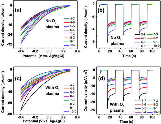
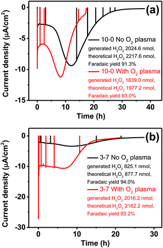
Having established, using the EPR method, the capacity of P3HT structures for photovoltage/photocurrent generation and encountering the limit caused by low intrinsic photovoltage generation, we next focused on three-electrode electrochemistry experiments to explore the full range of potential. In 3-electrode experiments, an applied external potential can probe the photogeneration and photofaradaic reactions without the imposed limit of internally-generated photovoltage. As is known, P3HT affords photocathodic behavior, where the dominant photofaradaic reaction is oxygen reduction.25,26,46,48 The results of cyclic voltammetry and pulsed-light chronoamperometry experiments for differently-structured P3HT samples, both before and after O2 plasma treatment, are shown in Fig. 8. In as-fabricated, non-treated samples (Fig. 8a and b), there is a clear trend of increased pore size/pore density leading to lower photochemical current. The highest photocurrent is present in the neat P3HT 10–0 sample, and then it declines for structured samples. Qualitatively, the photoelectrochemical behavior of all samples is the same, however. The treatment with O2 plasma changes the situation dramatically. Photocurrent in all cases increases relative to the untreated samples, with the largest differential being for the structured samples with highest porosity. The 3–7 P3HT–PS sample, for instance, shows the largest change, transitioning from the worst-performing samples in the series (max photocurrent roughly −18 μA cm−2 at −0.4 V), to the best-performing ones (−75 μA cm−2 at −0.4 V). The interpretation of this result we believe is related to the interplay of geometrically exposed surface and the wettability of that surface. Photoelectrochemistry of oxygen reduction requires water/protons, so wettability does play a role. On the other hand, a higher porosity exposes more surface but decreases wettability. In the end, the magnitude of photoelectrochemical current follows the same trend as the electrolytic capacitance shown in Fig. 6. Therefore, it would appear that registering electrochemical capacitance could be a relevant metric in tracking how nano/microstructuring affects faradaic behavior of semiconducting polymer electrodes.Having observed the impact of P3HT structuring on the photocathodic O2-reduction current, we proceeded with long-term photoelectrolysis experiments. In these, we compared neat P3HT samples with the best-performing structured ones, 3–7 P3HT–PS. We measured chronoamperometry at a fixed potential of 0 V vs. Ag/AgCl and continuous illumination and oxygenation (Fig. 9). The experiment is aimed to evaluate the stability of photocathodic oxygen reduction on P3HT, test if the increase in structuring provides a sustained benefit, and to quantify the product(s) of oxygen reduction. Once again, the positive effect of oxygen plasma treatment on photofaradaic current is evident. The plasma-treated 3–7 structured sample, moreover, affords a photocurrent that is nearly twice as high as the planar sample. Overall, the worst-performing sample of the series is the non-treated 3–7 structure, while its treated analogue performed the best. All samples retain photocurrent generation stability for roughly 10 hours, after this time a continuous decrease is observed. After a day, all samples cease to give photocurrent, and are visibly bleached, i.e. the samples are more transparent and the distinctive color of P3HT is clearly deteriorated. Oxygen-plasma treated samples generate more photocurrent, but degrade faster. Meanwhile, an interesting behavior observed for non-treated samples is that over the course of the first 10 hours of illumination, photocurrent actually increases, before peaking and then decreasing at a rate similar to the treated samples. This suggests a kind of activation of the surface that imparts it with similar catalytic properties as the oxygen-plasma treated samples. The observation that oxygenated water makes illuminated P3HT more hydrophilic was reported by Bellani et al.48 What is consistent in this picture is the presence of oxygen – clearly an oxygen-induced modification of the P3HT surface is conducive to the photofaradaic oxygen reduction reaction. As to the question of the product of the oxygen reduction reaction, we hypothesized, based on earlier indications from photochemical experiments,26 that hydrogen peroxide (H2O2) would be the dominant product. We utilized a dye/enzyme assay as described in previous works49 to quantify the amount of H2O2 produced over the course of the photoirradiation experiment. H2O2 can be the product of direct two-electron reduction of O2 or can be formed via single-electron reduction of O2 to superoxide, which via disproportionation of two superoxides yields H2O2. In any case, in a calculation of faradaic yield, the electron multiplicity for both pathways with respect to produced H2O2 is n = 2. We found that all the samples, regardless of the magnitude of photocurrent, had high faradaic yield 91–93% for H2O2 production. It can therefore be stated that our findings corroborate the growing body of evidence11,26,27 that P3HT, like many organic semiconductors, has a selectivity for oxygen reduction to H2O2 over other photocatalytic/photofaradaic processes. These values of faradaic yield compare favorably to other organic semiconductor photocathodes, where values in the range 70–96% have been reported depending on the materials and pH conditions.40,49 The results of the longer-term electrolysis experiments, taken together, indicate that P3HT is a relatively fragile semiconductor system for aqueous photoelectrochemistry.
Conclusions
In this work we have explored the effects of structuring thin films of the archetypical p-type organic semiconducting polymer P3HT. We have also sought to answer open questions about photoelectrochemical behavior of this material, including its photovoltage generation, electrochemical capacitance, products of faradaic oxygen reduction, and finally stability. The microphase separation method is a convenient and simple way to obtain structured thin films, and could be deployed on arbitrary substrates and likely with other semiconducting polymers. Structuring of the surface can substantially increase photoelectrochemical activity. In considering the (photo)electrochemical utility of the obtained film, both porosity and wettability are important factors. We have evaluated definitively that oxygen reduction, as the primary photofaradaic process occurring on P3HT, generates hydrogen peroxide as the dominant (90+%) product. The first critical limitation of P3HT is that very low photovoltages are intrinsically generated by the material. The second is that P3HT has limited stability, even in a photoelectrochemical cell with applied voltage removing photogenerated holes from the P3HT layer. The structuring, measurement techniques, and general principles that P3HT as a representative material have yielded in this study help to guide further research in the field of organic semiconductors for photoactive biointerfaces.Experimental methods
Materials
Poly(3-hexylthiophene) (P3HT, P3HT, regioregular, stereoregularity min 99%, TCI catalog# P2513, Mw 27–45k, max 100 ppm Pd) and n-octyltriethoxysilane (OTS) were purchased from TCI. Polystyrene, PS, with an average molecular weight of 35![[thin space (1/6-em)]](https://www.rsc.org/images/entities/char_2009.gif) 000 was supplied by Sigma Aldrich. Indium Tin Oxide (ITO) 15–20 Ω sq.−1 deposited on 1.1 mm thick borosilicate glass (Kintec) was used as a semitransparent conducting substrate throughout this work. All other chemicals were obtained from Sigma-Aldrich and used without any purification.
000 was supplied by Sigma Aldrich. Indium Tin Oxide (ITO) 15–20 Ω sq.−1 deposited on 1.1 mm thick borosilicate glass (Kintec) was used as a semitransparent conducting substrate throughout this work. All other chemicals were obtained from Sigma-Aldrich and used without any purification.
Fabrication of the photoelectrodes
ITO substrates were cut in the size of 2 cm × 2 cm and cleaned by sequential sonication in acetone (15 min), isopropanol (15 min), and finally deionized water (DI) (15 min). After drying under a stream of N2, these ITO substrates were exposed to O2 plasma (100 W, 5 min) and then silanized in a vapor of OTS at 90 °C for 2 hours. Finally, the ITO substrates were sonicated in acetone and washed with DI water to remove any OTS multilayers. 160 μl P3HT and PS solution (both dissolved in chlorobenzene) were spin-casted on the ITO side (30 s, 1000 rpm). The details of the contents of P3HT and PS used for the fabrication of photoelectrodes are listed in Table 1. Micro-phase separation occurs during the spin-coating process, resulting the formation of P3HT-rich phase and PS-rich phase on the ITO substrate. The PS phase was removed through washing with acetone overnight. O2 plasma application was kept constant for all “O2-plasma” samples (12.5 W, 13.56 MHz, 60 s).| P3HT–PS | P3HT–PS | P3HT–PS | P3HT–PS | P3HT–PS | P3HT–PS | P3HT–PS | P3HT–PS | |
|---|---|---|---|---|---|---|---|---|
| 10–0 | 9–1 | 8–2 | 7–3 | 6–4 | 5–5 | 4–6 | 3–7 | |
| P3HT (mg ml−1) | 10 | 10 | 10 | 10 | 10 | 10 | 10 | 10 |
| PS (mg ml−1) | 0 | 1.11 | 2.5 | 4.29 | 6.67 | 10 | 15 | 23.33 |
Microscopy and characterization
AFM measurements were conducted on a Dimension 3100 microscope equipped with a Nanoscope III controller from Bruker-Nano. Experiments were performed in ambient conditions using tapping mode. Si cantilevers with resonance frequency in the 150–300 kHz range are used. For SEM measurements a ZEISS Sigma 500 FE-SEM was used. SEM images were obtained after contacting of the ITO substrate to the sample stage, using copper tape. No additional conductive coatings were applied, as the conductivity of the ITO underlying the thin P3HT sample was found to be sufficient to prevent charging even up to acceleration voltages of 5 kV. Images were obtained using 4 kV acceleration voltage and secondary electron detectors, typically using mixed signals from the in-lens secondary electron detector as well as the SE2 detector to give the image better topographical perspective. The SE2 signal was favored (50+%) over in-lens to provide better topographical contrast, at the cost of high lateral resolution. The contact angle measurements were carried out in static mode on a Surface Tension Meter CAM200 (KSV Instruments). Deionised water drops of 5 μL were dispensed via standard a 10 μL-pipette. For each sample, 10 measurements were done and the mean was calculated.Electrochemical characterization
EPR was performed in 0.1 M KCl electrolyte using pulsed illumination (10 ms, 515 nm) at an irradiance of 50 mW cm−2 using the setup and techniques described previously.41 Electrochemical measurements of the photocathodes were performed in a three-electrode system, with a Pt coil as counter electrode, and the Ag/AgCl wire in 3 KCl as a reference electrode, with an Ivium technologies Vertex One potentiostat. All electrodes were placed in a Redox.me MM PEC H-CELL with two electrolyte chambers separated with a Nafion membrane, containing about 12 ml of electrolyte, (H2SO4, pH = 1). The active area of the sample mounted in the H-cell is limited to 1.0 cm2. For the photoelectrochemical measurements, a tungsten halogen lamp (calibrated to 100 mW cm−2, 1.00 sun) was used as a light source. The cathodic compartment was constantly purged with O2 during all measurements. All samples were illuminated from the substrate side, i.e. through the ITO. The cyclic voltammetry experiments were performed with the 20 mV s−1 scan rate within +0.3 V to −0.4 V range. For the capacitance measurements, the cathodic compartment was firstly purged with N2 for one hour and then cyclic voltammetry experiments were performed with the 100 mV s−1 scan rate within +0.3 V to −0.4 V range without any light source. N2 purging was done to eliminate the contribution of the oxygen reduction reaction to the current under cathodic polarizations.Determination of hydrogen peroxide concentration and faradaic efficiency
The quantification of the produced hydrogen peroxide was done spectrophotometrically by following the oxidation of 3,3′,5,5′-tetramethylbenzidine (TMB) in the presence of horseradish peroxidase (HRP) and citric acid–phosphate buffer solutions. Values of absorbance were measured at 653 nm with Synergy H1 Microplate reader (BioTek® Instruments, Inc.) in 96-well polystyrene flat bottom plates. Depending on hydrogen peroxide concentration in the sample, aliquots of different volumes (10–50 μl) were taken and added to a corresponding volume of HRP/TMB/buffer solution, in every case giving 300 μl of the solution. The obtained absorbance values were recalculated to concentration values basing on calibration curve formulas (R2 > 0.998 in every case). Faradaic efficiencies of the photoelectrolysis processes were determined basing on H2O2 concentration, electrolyte volume and theoretical molar amount of H2O2 generated (based on Faraday's law and integrated current).Conflicts of interest
The authors declare no conflicts of interest.Acknowledgements
The authors gratefully acknowledge financial support from the Knut and Alice Wallenberg Foundation within the framework of the Wallenberg Wood Science Centre 2.0, and the Wallenberg Centre for Molecular Medicine at Linköping, and the Swedish Foundation for Strategic Research (SSF). We are grateful for support from the National Science Centre, Poland within grant 2019/33/B/ST5/01212.References
- M. Grätzel, Nature, 2001, 414, 338–344 CrossRef PubMed.
- Semiconductor electrochemistry, ed. R. Memming, Wiley-VCH, Weinheim, 2nd edn, 2016 Search PubMed.
- M. J. Sailor, Porous Silicon in Practice, Wiley-VCH, Weinheim, 2011 Search PubMed.
- T. Hisatomi, J. Kubota and K. Domen, Chem. Soc. Rev., 2014, 43, 7520–7535 RSC.
- D. T. Simon, E. O. Gabrielsson, K. Tybrandt and M. Berggren, Chem. Rev., 2016, 116, 13009–13041 CrossRef CAS PubMed.
- S. Inal, J. Rivnay, A. O. Suiu, G. G. Malliaras and I. McCulloch, Acc. Chem. Res., 2018, 51, 1368–1376 CrossRef CAS PubMed.
- D. Rand, M. Jakešová, G. Lubin, I. Vebraite, M. David-Pur, V. Đerek, T. Cramer, N. S. Sariciftci, Y. Hanein and E. D. Głowacki, Adv. Mater., 2018, 30, 1707292 CrossRef PubMed.
- N. Martino, P. Feyen, M. Porro, C. Bossio, E. Zucchetti, D. Ghezzi, F. Benfenati, G. Lanzani and M. R. Antognazza, Sci. Rep., 2015, 5, 8911 CrossRef CAS PubMed.
- M. Sytnyk, M. Jakešová, M. Litviňuková, O. Mashkov, D. Kriegner, J. Stangl, J. Nebesářová, F. W. Fecher, W. Schöfberger, N. S. Sariciftci, R. Schindl, W. Heiss and E. D. Głowacki, Nat. Commun., 2017, 8, 91 CrossRef PubMed.
- F. Lodola, V. Rosti, G. Tullii, A. Desii, L. Tapella, P. Catarsi, D. Lim, F. Moccia and M. R. Antognazza, Sci. Adv., 2019, 5, eaav4620 CrossRef CAS PubMed.
- M. R. Antognazza, I. A. Aziz and F. Lodola, Oxid. Med. Cell. Longevity, 2019, 2019, 2867516 Search PubMed.
- M. Gryszel and E. D. Głowacki, Chem. Commun., 2020, 56, 1705–1708 RSC.
- M. C. Scharber, D. Mühlbacher, M. Koppe, P. Denk, C. Waldauf, A. J. Heeger and C. J. Brabec, Adv. Mater., 2006, 18, 789–794 CrossRef CAS.
- F. Benfenati and G. Lanzani, Lab. Anim., 2018, 47, 71–75 CrossRef PubMed.
- E. Macchia, R. A. Picca, K. Manoli, C. Di Franco, D. Blasi, L. Sarcina, N. Ditaranto, N. Cioffi, R. Österbacka, G. Scamarcio, F. Torricelli and L. Torsi, Mater. Horiz., 2020, 7, 999–1013 RSC.
- J. K. Harris, B. Neelamraju and E. L. Ratcliff, Chem. Mater., 2019, 31, 6870–6879 CrossRef CAS.
- G. Manfredi, E. Colombo, J. Barsotti, F. Benfenati and G. Lanzani, Annu. Rev. Phys. Chem., 2019, 70, 99–121 CrossRef CAS PubMed.
- O. S. Abdullaeva, F. Balzer, M. Schulz, J. Parisi, A. Lützen, K. Dedek and M. Schiek, Adv. Funct. Mater., 2018, 1805177 Search PubMed.
- V. Gautam, D. Rand, Y. Hanein and K. S. Narayan, Adv. Mater., 2014, 26, 1751–1756 CrossRef CAS PubMed.
- J. Hopkins, L. Travaglini, A. Lauto, T. Cramer, B. Fraboni, J. Seidel and D. Mawad, Adv. Mater. Technol., 2019, 1800744 CrossRef.
- C. Tortiglione, M. R. Antognazza, A. Tino, C. Bossio, V. Marchesano, A. Bauduin, M. Zangoli, S. V. Morata and G. Lanzani, Sci. Adv., 2017, 3, e1601699 CrossRef PubMed.
- J. F. Maya-Vetencourt, D. Ghezzi, M. R. Antognazza, E. Colombo, M. Mete, P. Feyen, A. Desii, A. Buschiazzo, M. Di Paolo, S. Di Marco, F. Ticconi, L. Emionite, D. Shmal, C. Marini, I. Donelli, G. Freddi, R. Maccarone, S. Bisti, G. Sambuceti, G. Pertile, G. Lanzani and F. Benfenati, Nat. Mater., 2017, 16, 681–689 CrossRef CAS PubMed.
- M. Zangoli, F. Di Maria, E. Zucchetti, C. Bossio, M. R. Antognazza, G. Lanzani, R. Mazzaro, F. Corticelli, M. Baroncini and G. Barbarella, Nanoscale, 2017, 9, 9202–9209 RSC.
- G. Tullii, F. Giona, F. Lodola, S. Bonfadini, C. Bossio, S. Varo, A. Desii, L. Criante, C. Sala, M. Pasini, C. Verpelli, F. Galeotti and M. R. Antognazza, ACS Appl. Mater. Interfaces, 2019, 11, 28125–28137 CrossRef CAS PubMed.
- G. M. Suppes, P. J. Fortin and S. Holdcroft, J. Electrochem. Soc., 2015, 162, H551–H556 CrossRef CAS.
- M. Gryszel, M. Sytnyk, M. Jakesova, G. Romanazzi, R. Gabrielsson, W. Heiss and E. D. Głowacki, ACS Appl. Mater. Interfaces, 2018, 10, 13253–13257 CrossRef CAS PubMed.
- M. Moros, A. Lewinska, G. Onorato, M. R. Antognazza, F. Di Maria, M. Blasio, G. Lanzani, A. Tino, M. Wnuk and C. Tortiglione, MRS Commun., 2018, 8, 918–925 CrossRef CAS.
- S. Bellani, M. R. Antognazza and F. Bonaccorso, Adv. Mater., 2018, 1801446 Search PubMed.
- P. Westacott, J. R. Tumbleston, S. Shoaee, S. Fearn, J. H. Bannock, J. B. Gilchrist, S. Heutz, J. Demello, M. Heeney, H. Ade, J. Durrant, D. S. McPhail and N. Stingelin, Energy Environ. Sci., 2013, 6, 2756–2764 RSC.
- M. Rudolph and E. L. Ratcliff, Nat. Commun., 2017, 8, 1048 CrossRef CAS PubMed.
- B. Neelamraju, M. Rudolph and E. L. Ratcliff, J. Phys. Chem. C, 2018, 122, 21210–21215 CrossRef CAS.
- E. Daviddi, Z. Chen, B. Beam Massani, J. Lee, C. L. Bentley, P. R. Unwin and E. L. Ratcliff, ACS Nano, 2019, 13, 13271–13284 CrossRef CAS PubMed.
- V. Vohra, M. Campoy-Quiles, M. Garriga and H. Murata, J. Mater. Chem., 2012, 22, 20017–20025 RSC.
- V. Vohra, O. Notoya, T. Huang, M. Yamaguchi and H. Murata, Polymer, 2014, 55, 2213–2219 CrossRef CAS.
- S. Guo, Y. Lu, B. Wang, C. Shen, J. Chen, G. Reiter and B. Zhang, Soft Matter, 2019, 15, 2981–2989 RSC.
- E. Ueda and P. A. Levkin, Adv. Mater., 2013, 25, 1234–1247 CrossRef CAS PubMed.
- A. J. Bard and L. R. Faulkner, Electrochemical Methods Fundamentals and Applications, John Wiley & Sons, New York, 2nd edn, 2001, vol. 2 Search PubMed.
- K. Melzer, M. Brändlein, B. Popescu, D. Popescu, P. Lugli and G. Scarpa, Faraday Discuss., 2014, 174, 399–411 RSC.
- T. Cramer, a Kyndiah, M. Murgia, F. Leonardi, S. Casalini and F. Biscarini, Appl. Phys. Lett., 2012, 100, 143302 CrossRef.
- M. Gryszel, A. Markov, M. Vagin and E. D. Głowacki, J. Mater. Chem. A, 2018, 6, 24709–24716 RSC.
- M. Jakešová, M. S. Ejneby, V. Đerek, T. Schmidt, M. Gryszel, J. Brask, R. Schindl, D. T. Simon, M. Berggren, F. Elinder and E. D. Głowacki, Sci. Adv., 2019, 5, eaav5265 CrossRef PubMed.
- V. Đerek, D. Rand, L. Migliaccio, Y. Hanein, E. D. Głowacki and M. R. Antognazza, Front. Bioeng. Biotechnol., 2020, 8, 284 CrossRef PubMed.
- Z. Chiguvare, J. Parisi and V. Dyakonov, Z. Naturforsch., A: Phys. Sci., 2007, 62, 609–619 CAS.
- J. H. Bombile, M. J. Janik and S. T. Milner, Phys. Chem. Chem. Phys., 2019, 21, 11999–12011 RSC.
- Z. Chiguvare and V. Dyakonov, Phys. Rev. B: Condens. Matter Mater. Phys., 2004, 70, 1–8 CrossRef.
- S. Bellani, A. Ghadirzadeh, L. Meda, A. Savoini, A. Tacca, G. Marra, R. Meira, J. Morgado, F. Di Fonzo and M. R. Antognazza, Adv. Funct. Mater., 2015, 25, 4531–4538 CrossRef CAS.
- M. S. Ejneby, L. Migliaccio, M. Gicevic, M. Jakešová, F. Elinder and E. D. Głowacki, Adv. Mater. Technol., 2020, 5, 1900860 CrossRef.
- S. Bellani, D. Fazzi, P. Bruno, E. Giussani, E. V. Canesi, G. Lanzani and M. R. Antognazza, J. Phys. Chem. C, 2014, 118, 6291–6299 CrossRef CAS.
- M. Jakešová, D. H. Apaydin, M. Sytnyk, K. Oppelt, W. Heiss, N. S. Sariciftci and E. D. Głowacki, Adv. Funct. Mater., 2016, 26, 5248–5254 CrossRef.
| This journal is © The Royal Society of Chemistry 2020 |

