Recent progress in well-defined higher azaacenes (n ≥ 6): synthesis, molecular packing, and applications
Zhongbo
Zhang
 and
Qichun
Zhang
 *
*
School of Materials Science and Engineering, Nanyang Technological University, Singapore 639798, Singapore. E-mail: qczhang@ntu.edu.sg
First published on 19th December 2019
Abstract
In this review, we will focus on the recent progress in the synthetic strategies, photo-electronic properties, molecular packing modes and applications of azaacenes (n ≥ 6) with single-crystal structures. We will summarize the synthetic methods to approach larger azaacenes and elaborate the relationships between their molecular structures (solid stacking) and their photo-electronic properties. Moreover, the device applications of azaacenes as organic semiconductors are also reviewed.
1. Introduction
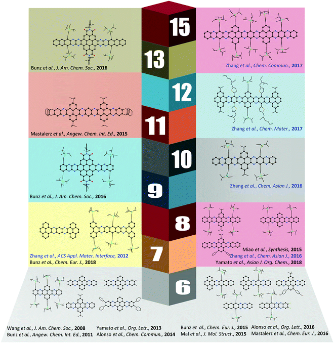
Although the first azaacene 1 (Fig. 1) was reported by Kummer and Zimmermann in 1967,1 this field didn’t cause too much research interest over several decades. In 2003, Nuckolls et al. first demonstrated that dihydrodiazopentacenes showed good p-type semiconductor behaviours in organic field effect transistors (OFET).2 This discovery made researchers realize the tremendous potential of hydroazaacenes/azaacenes in organic electronics. Since then, many synthetic methods such as condensation reactions,3–5 Diels–Alder cycloaddition reactions,6 palladium-catalysed coupling reactions,7etc.8–13 have been developed to prepare a large number of azaacenes.14 Besides synthesis, more and more azaacenes have been considered as active elements in OFETs,9–12,15 organic light emitting diodes (OLEDs),16–20 molecular conductors,21 sensors,22–26 phototransistors,27 solar cells,28 electron-transport layers,29–32 memory devices,33–37etc.38–41 Especially in OFETs, azapentacenes displayed p-type,10,11 ambipolar,9–12 or n-type11,15 charge transport properties through changing the number and position of sp2 N atoms on the backbone. Specifically, the electron mobility based on halogenated tetraazapentacenes can reach 27.8 cm2 V−1 s−1, which is a new record for n-channel OFETs.15Like the acene system,42,43 when the number of fused rings increases, their instability in air or under light, as well as the decreasing solubility, makes the approach of higher azaacenes more challenging. To address these issues, many strategies have been developed. For example, to prevent the dimerization of azahexacenes44–46 and azaheptacenes,47 the Bunz group tried to approach them through attaching larger silylethynyl groups (triisopropyl or triisobutyl) on their backbone. However, it turns out that this method is not always successful and effective.46,47 Another method to prepare larger azaacenes is the introduction of pyrene units as building blocks into the framework. This strategy can not only stabilize the as-prepared larger azaacenes due to the conjugated nature of the pyrene units, but also can modify their solubility through attaching bulky groups on the pyrene units.48,49 The first report of a pyrene-fused azaacene (PFA) 2 (Fig. 1) can be traced back to 1937 by Vollmann, and the only characterization data for this molecule is its melting point.50 However, at that time, the tedious multistep synthetic route to prepare pyrene diketone and tetraone became a limitation of their wide usage. In 2005, the Harris group invented an efficient oxidation method that shortened the preparation of pyrene diketone and tetraone to one step.51 Since then, diverse pyrene diketones and tetraones have been synthesized by this general and compatible method, which renders pyrene units as popular building blocks in the construction of azaacenes.48 In 2015, the Kaafarani group characterized the structure of molecule 2 by single crystal X-ray diffraction analysis.52 As the conjugated backbone extends, larger azaacenes may show unique properties similar to fully conjugated ladder polymers,41 which might endow larger azaacenes with better performance in organic electronics. Till now, there are in total five larger structure-well-defined azaacenes with the number of linearly-fused benzene rings larger than or equal to 1039,53–56 (Fig. 2), and the longest one with a single-crystal structure contains 15 linearly-fused rings.56
Since the intermolecular packing and interactions play a crucial role in determining the optical and electrical properties of organic semiconductors,57 obtaining suitable single crystals of azaacenes for single-crystal X-ray diffraction analysis is highly desirable and very important. The reason is that single crystals can present a clear picture of molecular structure and intermolecular stacking, which provides an important bridge to understand the relationships between the structure and properties and in turn helps to design new organic semiconductors with excellent performance. It is necessary to summarize these azaacenes with single crystal structures and reveal their structure–property relationships. Because the azapentacenes have already been reviewed by the Miao group,58,59 this article will only focus on higher azaacenes (Fig. 2, more than five linearly-fused rings, n ≥ 6) with single crystal structures (the molecules published by our group have been described in a blue colour). Their synthesis, structures and applications in the recent literature will be summarized.
2. Synthetic strategies of azaacenes
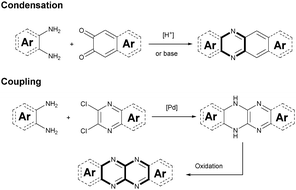
Although plenty of azaacenes (n ≥ 6) with novel structures have been reported, the synthetic methods are summarized only by two methods: (1) direct condensation between an aromatic diamine (or tetraamine) and a diketone (or tetraone) catalyzed by an acid or base; and (2) a coupling reaction between aromatic diamines and o-dichloropyrazine derivatives, catalyzed by palladium and followed by oxidation (Scheme 1).2.1. Condensation reactions
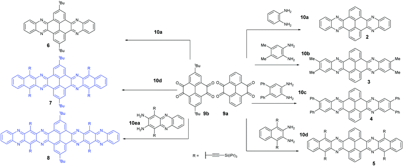
Condensation reactions are old and common methods to construct azaacenes from a diamine (or tetraamine) and a diketone (or tetraone). We classified them into three categories according to the different precursors in the condensation reactions: (A) condensation reactions between a tetraone and aromatic diamine, (B) condensation reactions between an aromatic tetraamine and diketone, and (C) condensation reactions between a diketone and aromatic diamine.Introducing pyrene units into the framework of azaacenes was first realized by Vollmann in 1937 through the condensation reaction between 9a and 10a, and the as-prepared compound was only characterized by its melting point due to the limited characterization tools.50 Later, this compound was re-synthesized by Stille and Mainen, and its ultraviolet-visible (UV-vis) absorption was examined.60 Recently, the Kaafarani group52 and Mastalerz group61 re-synthesized 2 in a yield of 92% and 87%, respectively. Moreover, they also used dimethyl substituted diamine 10b and two tert-butyl substituted tetraone (9b) to prepare 3 and 6, respectively (Scheme 2). Both structures were determined by single crystal X-ray diffraction analysis. Besides, 2 can also be obtained by a mechanochemical (ball-milling) method with a similar yield to the condensation reaction.62 In 2008, the Wang group reported 4 in 92% yield by choosing 10c as the diamine precursor for the condensation reaction.63 A larger pyrene-fused azaacene (PFA) 5 with eight linearly-fused rings has been prepared by the Miao group with a moderate yield of 54%, where the bulky triisopropylsilylethynyl (TIPS) groups of diamine 10d endowed 5 with good solubility in common solvents.64 In 2016, our group39 successfully prepared pyrene-fused tetraazaoctacene (7, 70%) and octaazadecacene (8, 51%) by the condensation reaction between tetraone 9b and diamines 10d or 10ea, respectively.
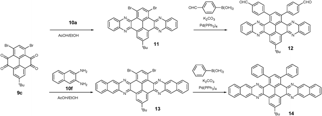
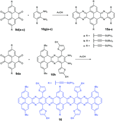
1,3-Dibromo-7-tert-butylpyrene-4,5,9,10-tetraone (9c) was prepared by the Yamato group. After condensation with diamine 10a or 10f, bromine-substituted PFA intermediates 11 or 13 were obtained. Following a further Suzuki cross-coupling reaction step, pyrene-fused tetraazahexane 1265 and tetraazaoctacene 1466 were easily prepared (Scheme 3). The Mateo-Alonso group67,68 reported an efficient synthetic route to synthesize three 2,7-substituted pyrene tetraones (9d(a–c)) as the building units for the construction of PFAs, and a series of tetraazahexacenes (15a–c) with six trialkylsilylethynyl groups were prepared. In 2017, our group synthesized a new intermediate diamine (10h), which has been employed to react with 9da to build PFA 16 containing twelve linearly-fused rings55 (Scheme 4).
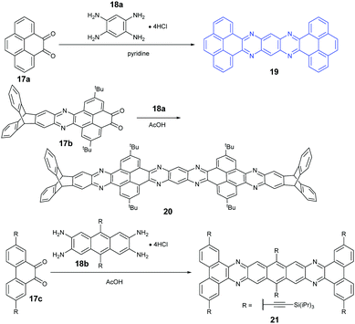
Because aromatic tetraamines cannot be prepared as easily as diamines, the number of PFAs with synthetic routes belonging to category B is only three (Scheme 5). Tetraazaheptacene (19) with two pyrenes as terminal units was first reported by the Mateo-Alonso group, where they only characterized it with 1H-NMR and HRMS due to its poor solubility.69 Fortunately, our group obtained its single crystals successfully through the physical vapor deposition method, and the phototransistor devices based on the crystals showed good performance.27 To increase the solubility of azaacenes, the usage of triptycenylene as the terminal unit has been demonstrated as an effective way.70 The Mastalerz group53 reported a large PFA (20) end-capped with two triptycenylene moieties containing eleven linearly-fused aromatic rings through the condensation reaction between 17b and 18a. Associated with the increasing length of azaacenes, the stability is another issue to be considered. Lateral benzannulation on the linear framework is an effective way to stabilize large acenes.71 Recently, the Bunz group applied this strategy to prepare tetraazaheptacene (21) through the condensation reaction between a diketone (17c) and tetraamine (18b). As it is expected, 21 showed very good stability.5
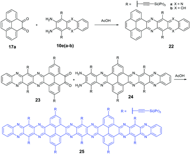
In 2016, the Mateo-Alonso group72 reported the synthesis of a K-conjugated diazahexacene (22a) and tetraazahexacene (22b) through the condensation reaction between diketone 17a and diamine 10ea or 10eb, respectively. Charge transport studies showed p-type transport for 22a and n-type transport for 22b. In 2017, our group constructed a larger PFA 25 containing fifteen linearly-fused aromatic rings through the condensation reaction between novel diketone 23 and diamine 24 in a yield of 46%. A single crystal of 25 has been obtained successfully, which is the longest azaacene confirmed by single-crystal X-ray diffraction so far56 (Scheme 6).
2.2. Palladium-catalyzed coupling reaction between diamines and dichloropyrazine derivatives
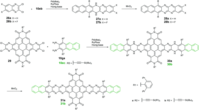
Palladium-catalyzed coupling reactions are a very common method to construct carbon–nitrogen bonds between aryl amines and aryl halides. The synthesis of azaacenes through the formation of two carbon–nitrogen bonds in one step by using palladium-catalyzed coupling is well worth exploring. The Bunz group reported two tetraazahexacene derivatives (28a–b).73,74 The synthetic route involved the palladium-catalyzed formation of N,N′-dihydroazahexacenes 27a and 27b from the reactions between silylethynyl-substituted diaminoanthracene (10eb) and 1,2-dichloroquinoxaline derivatives (26a–b) by using Pd(dba)2 as a catalyst and RuPhos as the ligand. The as-prepared dihydroazahexacene precursors can be further oxidized by manganese dioxide to afford 28a–b. In 2017, the same group reported coronene-containing azaacenes with nine linearly-annulated rings (31a) and thirteen linearly-annulated rings in a row (31b),75 where the first step is the synthesis of dihydroazahexacene precursors (30a and 30b) from a diamine (10ga or 10ec) and tetrachlorine-substituted coronene derivative (29), followed by the oxidization of manganese dioxide to yield the desired azaacenes (31a and 31b) (Scheme 7).3. Properties and single crystals of higher azaacenes (n ≥ 6)
3.1. Photo-electronic properties
The development of different building units that endowed azaacenes with diverse structures could make these azaacenes exhibit interesting photo-electronic properties. These achievements would provide scientists a great opportunity to understand the effect of the conjugation length, the number and position of sp2 N atoms, and different substituted groups on their photo-electronic properties. Compounds 2–4 are PFAs with the same backbone but different terminal substituents. Compound 3 with four methyl groups at the terminals showed an average 3 meV redshift for the longest wavelength absorption bands compared with 2 without any terminal substituents.52 The reason is that the slight electron-donating effect of the methyl groups could elevate the energy level of the highest occupied molecular orbital (HOMO) of 3. When four phenyl groups were used as terminal substituents in 4, a redshift of 24 nm in absorption with a decreased optical bandgap of 2.78 eV63 (Table 1) was observed. Similar substituent effects can also be found in 28a–b.44,45 The absorption onset of 28a was located at 862 nm, while the absorption onset of 28b was bathochromically shifted to 1000 nm, which can be explained through the efficient stabilization of the lowest unoccupied molecular orbital (LUMO) by the electronegative substituents (the fluorine atoms on the end of the backbone). The absorption spectra of 22a–b have a similar trend, and both exhibited two sets of bands in the visible region with clear vibrionic characteristics72 (Fig. 3a). The optical bandgaps of 22a and 22b are estimated by the onset of absorption, corresponding to 1.85 and 1.81 eV, respectively. The photoluminescence spectra of 22a and 22b showed emission bands with shoulder peaks that cover from red to near infrared (peak maxima of 661 and 683 nm, respectively (Fig. 3b)). The cyclic voltammogram (CV) of 22b demonstrated two consecutive reversible reduction processes and one reversible oxidation process. 22a exhibited the same reduction pattern (two consecutive reversible reduction processes, but no signs of a reversible oxidation process (Fig. 3c)). The reduction potentials of 22a were anodically shifted compared with 22b. The LUMOs of 22a and 22b are −3.89 and −3.57 eV, respectively. For 22a, the two additional sp2 nitrogen atoms in the aromatic skeleton endowed it with a 0.3 eV lower LUMO compared to that of 22b.| Compound | Gapopt (eV) | HOMO (eV) | LUMO (eV) | Packing model | Intermolecular interactions | Ref. |
|---|---|---|---|---|---|---|
| a Optical bandgap estimated by its UV-vis spectrum. b Energy level calculated from cyclic voltammograms. c Energy level calculated from CV data and the optical bandgap. | ||||||
| 2 | 2.90a | — | — | Herringbone packing | π–π (3.41 Å) | 52 and 61 |
| 3 | 2.86a | — | — | Herringbone packing | π–π (3.45 Å) | 52 |
| 4 | 2.78 | −6.03c | −3.25b | Face to face π stack | π–π (3.48 Å) | 63 |
| 5 | — | — | — | Herringbone packing | No π overlap | 64 |
| 6 | — | — | — | Herringbone packing | π–π (3.44 Å), CH–π | 61 |
| 7 | 2.19 | −5.27c | −3.08b | Herringbone packing | No π overlap | 39 |
| 8 | 1.86 | −5.54c | −3.68b | Brickwork packing | π–π (3.23 & 3.27 Å) | 39 |
| 12 | 2.85 | −6.02b | −3.17c | Face to face π stacking | π–π (3.58 Å) | 65 |
| 14 | 2.65 | −5.96b | −3.31c | Face to face π stacking | π–π (3.82 & 3.75 Å) | 66 |
| 15a | 2.69 | −6.08c | −3.39b | Herringbone packing | No π overlap | 68 |
| 15b | 2.69 | −6.15c | −3.46b | Herringbone packing | No π overlap | 68 |
| 15c | 2.72 | −6.26c | −3.54b | Herringbone packing | No π overlap | 68 |
| 16 | 1.30 | −5.00b | −3.50b | Face to face π stacking | π–π (3.32 Å) | 55 |
| 19 | — | — | — | Face to face π stacking | π–π (3.39 Å) | 27 |
| 21 | — | — | −3.88b | Herringbone packing | No π overlap | 5 |
| 22a | 1.85 | −5.74c | −3.89b | Brickwork packing | π–π (3.233 Å) | 72 |
| 22b | 1.81 | −5.43b | −3.57b | Brickwork packing | π–π (3.397 Å) | 72 |
| 25 | 1.85 | −5.59c | −3.74b | Herringbone packing | π–π (3.38 Å) | 56 |
| 28a | 1.44 | −5.59c | −4.15b | Brickwork packing | π–π (3.33 & 3.31 Å) | 44 |
| 28b | 1.24 | −5.41c | −4.17b | Brickwork packing | π–π (3.30 & 3.31 Å) | 45 |
| 31b | 1.03 | −5.46c | −4.43b | Face to face π stacking | π–π (3.38 Å) | 54 |
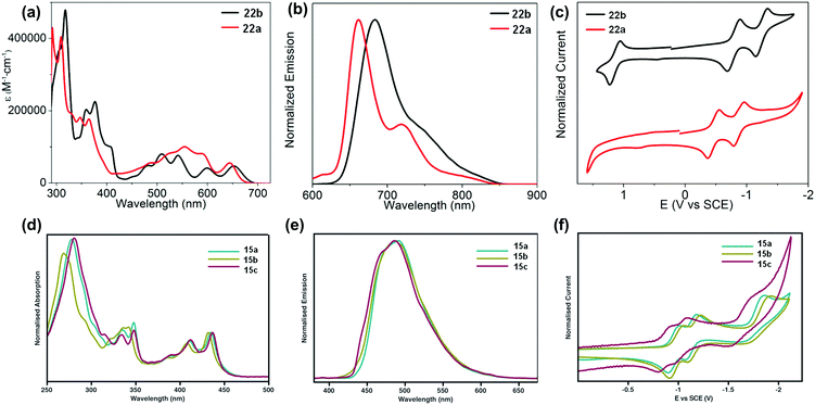 | ||
| Fig. 3 UV-vis absorption (a) and photoluminescence (b) spectra of 22a–b in o-DCB. (c) Cyclic voltammograms of 22a–b in 0.1 M n-Bu4NPF6 in o-DCB. (d) Absorption of 15a–c. (e) Emission (λex = 350 nm) of 15a–c in THF. (f) Cyclic voltammograms of 15a–c in THF (0.1 M n-Bu4NPF6). (a)–(c) are reproduced with permission from ref. 72. Copyright 2016, American Chemical Society. (d)–(f) are reprinted with permission from ref. 68. Copyright 2014, Royal Society of Chemistry. | ||
The absorption spectra of 15a–c showed good resolution of vibrionic bands in the UV and visible regions, consistent with the molecular structures.68 Almost the same absorption characteristics were observed for 15a–c, except that some difference was noticeable in the UV region of 15b (Fig. 3d). The maximum emission peaks for 15a–c were located at 489, 487 and 485 nm, respectively (Fig. 3e). From cyclic voltammograms, the LUMO levels were estimated from the onsets of the first reduction waves, which are consistent with the electron nature of their substituents. The small effect from the alkyl nature of the TIPS and triisobutylsilylethynyl (TIBS) substituents endowed 15a and 15b with similar LUMO levels (−3.39 eV and −3.46 eV), while the more electron withdrawing character of the triphenylsilyl group lowered the LUMO of 15c considerably to −3.54 eV (Fig. 3f).
The normalized UV-vis absorption spectra of 7 and 8 in dichloromethane39 are shown in Fig. 4a. Both displayed four absorption peaks in the visible region, while 8 spanned a wider range compared with that of 7. Moreover, the obvious bathochromically-shifted absorption indicated that 8 had a reduced optical band gap of 1.86 eV compared to that of 7 (2.19 eV), attributed to the increased conjugation length. The LUMO levels of 7 and 8 correspond to −3.08 and −3.68 eV, respectively (Fig. 4b), and the lower LUMO level of 8 than that of 7 is ascribed to the four additional N atoms in the backbone. In the UV-vis absorption spectrum of 25 (Fig. 4c), four absorption peaks were observed in the region from 400 nm to 700 nm.56 The optical band gap is 1.85 eV (estimated from the onset of absorption), which is very similar to that of octazadecacene.39 This phenomenon comes from the cross-conjugated nature of the pyrene unit: although the skeleton of 25 is conjugated, the aromaticity breaks at the pyrene unit. According to Clar's rule, one pyrene unit can add two aromatic π-sextets in the conjugated skeleton,76 which effectively increase the stability of large acenes. The π–π interactions and fluorescence quenching of intermolecular interactions can be effectively suppressed by steric hindrance from TIPS groups at the periphery of the conjugated skeleton. In addition, TIPS groups also increased the solubility. The maximum emission of 25 was located at 661 nm when excited at 530 nm (Fig. 4c). However, the fluorescence quantum yield of 25 is only 3%, which can be ascribed to the self-absorption effect caused by the broad overlap between the PL and UV-vis spectra as well as non-radiative transition processes. As shown in Fig. 4d, 25 showed three reversible reduction peaks, and the LUMO level was calculated to be −3.74 eV from the onset of the first reduction wave.
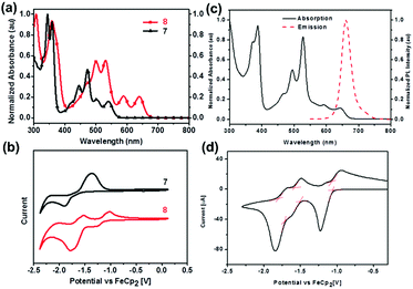 | ||
| Fig. 4 (a) UV-vis absorption spectra of 7 and 8 in dichloromethane. (b) CV curves of 7 and 8 in dichloromethane/0.1 M n-Bu4NPF6 (externally referenced against ferrocene/ferrocenium). (c) UV-vis absorption spectrum and fluorescence emission spectrum of 25 in dichloromethane (λex = 530 nm). (d) CV curve of 25 (electrolyte: 0.1 M n-Bu4NPF6, scanning speed: 50 mV s−1). (a) and (b) are reproduced with permission from ref. 39. Copyright 2016, Wiley-VCH. (c) and (d) are reprinted with permission from ref. 56. Copyright 2017, Royal Society of Chemistry. | ||
3.2. Molecular structures and packing models
The packing pattern can be affected by many factors, such as the backbone length, the numbers and positions of N atoms on the backbone, the differences of side chains and their positions, and even the solvent for growing crystals, etc. Thus, it is necessary to figure out the relationships between the molecular structure and the packing model, then guiding molecular design to achieve high performance materials, since the packing model of azaacenes plays a very important role in determining their performance in device applications. There are four kinds of main packing motifs: (A) herringbone packing with π–π overlap between adjacent molecules; (B) herringbone packing without π–π overlap between adjacent molecules; (C) one-dimensional face to face π stacking; and (D) brickwork packing.Compound 2 without side chains on the backbone is a planar molecule, which favours herringbone-type packing.52 The distance between the π planes of two adjacent molecules is 3.41 Å. When small groups such as methyl groups on the tail (3)52 or two tert-butyl groups at the 2,7-positions of the pyrene unit (6)61 are added on the backbone, the planarity of the molecules has no changes, while the π–π stacking distance is affected. The π–π distance increased to 3.45 and 3.44 Å for 3 and 6, respectively. Moreover, the tert-butyl groups in 6 also have interactions with the adjacent layer through C–H–π interactions. When the groups on the backbone become larger and larger, both the planarity and molecular packing model change. Compounds 15 have six connected trialkylsilylethynyl groups on the framework, resulting in alternating twisted structures68 (Fig. 5). The pyrene unit is tilted from the plane, and the π–π overlap is prevented by steric stress from large substituents on the framework. Similar results have also been found in tetraazaheptacene (21)5 and tetraazaoctacenes (564 and 739) that also have large steric hindrance substituents. All these three azaacene molecules packed in a herringbone-type mode without π–π overlapping.
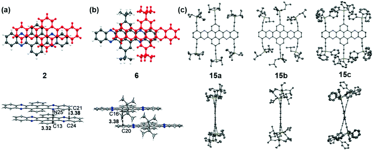 | ||
| Fig. 5 Front (top) and side (bottom) views of compound 2, 6 and 15a–c. (a) and (b) are reproduced with permission from ref. 61. Copyright 2016, Wiley-VCH. (c) is reproduced with permission from ref. 68. Copyright 2014, Royal Society of Chemistry. | ||
Compound 25 with fifteen linearly-fused rings in a row is the longest azaacene, whose structure has been confirmed by single crystal X-ray diffraction analysis54 (Fig. 6). The packing motif of 25 is somewhat special compared to the above-mentioned azaacenes. First, two adjacent molecules formed a dimer with slight overlap, then the as-formed dimer packed in a herringbone mode. The distance between the π planes of the formed dimer is 3.38 Å, which suggested the existence of π–π interactions of these two adjacent molecules.
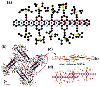 | ||
| Fig. 6 (a) Molecular structure. (b) The crystal packing mode of 25 shows that two adjacent molecules form a dimer first, then 1,4-dioxane molecules are encaged (just the O atoms are shown here) in the crystal voids formed by the four dimers. (c) The side view of the dimer shows a dual-bending feature with a short distance of about 3.38 Å between the adjacent π-planes. (d) The top view of the dimer indicates that the degree of overlap of the adjacent π-planes is very small. Reprinted with permission from ref. 56. Copyright 2017, Royal Society of Chemistry. | ||
Compound 363 with four phenyl groups on the terminals adopted one-dimensional face-to-face π stacking with a distance of 3.48 Å, which is totally different from 2. The side phenyl groups result in a similar change in the molecular packing of 12.65 One-dimensional face-to-face π stacking was observed with a distance of 3.58 Å, which is longer than the value of 3, attributed to the larger twist angles between the formylphenyl groups and the pyrene unit. As two more benzene rings are fused on the terminals, the centroid–centroid distances of two adjacent molecules of 14 are further increased to 3.82 Å and 3.75 Å respectively, which also causes a slip of two neighboring molecules.66 Compound 31b,54 a coronene-containing azaacene with thirteen linearly-fused rings, shows a fully planar π system. The twist angle between the two diisopropylphenyl substituents at the bisimide moiety and the aromatic core is 72°. The packing mode features slipped one-dimensional π stacking with a mean plane distance of 3.38 Å (Fig. 7c). Azaacenes end-capped with two pyrene units (16 and 19) always favour one-dimensional π stacking. For compound 1655 (Fig. 7b), the two pyrene units at the terminals are parallel to each other, and the dihedral angle between the end-capping pyrene rings and the center pyrene unit is 2.84°. One molecule is strongly affected by its adjacent molecules (above and below) with a mean distance of 3.32 Å between them, which suggests strong π–π interactions among adjacent molecules. In addition to the one-dimensional stacking of the closest molecules, a zigzag packing motif can also be observed, which is attributed to the backbone plane, resulting in a slipping distance of 4.77 Å between neighboring molecules (Fig. 7a). The migration of phenyl groups from the terminal to the 1,3-sites of the core pyrene unit leads to a large number of C–H intermolecular interactions. It is worth noting that the molecular backbone and packing model can be significantly affected by the solvents for crystal growth. For compound 20, its crystals can be obtained from ortho-dichlorobenzene (o-DCB) and chloroform, respectively, which showed very different molecular structures and stacking models.53 Crystals grown from o-DCB showed a nearly planar π plane, and two coplanarly-arranged o-DCB molecules are located at the voids between the π planes, resulting in an increased distance between 6.8 and 6.9 Å of two adjacent molecules. By contrast, crystals grown from chloroform exhibited an asymmetric motif and two independent molecular structures. One molecule is nearly planar, but the other is bent. The planar one is similar to the unit found in o-DCB, and the bending angle of the other one is around 26.48°. In addition, two bent molecules are enclathrated by strong π–π interactions with an interplanar distance of 3.31 Å.
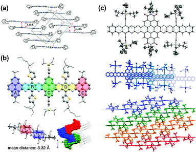 | ||
| Fig. 7 (a) Crystal packing of compound 4. (b) Single-crystal X-ray structure of 16, top: molecular structure. Bottom left: The arrangement of the neighbouring molecules shows a 1D stacking motif. The mean distance of two adjacent molecules is 3.32 Å. Bottom right: Crystal packing along a nonspecial crystallographic direction. (c) Top: Molecular structure of 31b (50% probability plot), middle: top view of 1D stacks in the crystal of 31b. Bottom: Side view of the arrangement of neighbouring stacks of 31b. (a) is reprinted with permission from ref. 63. Copyright 2008, American Chemical Society. (b) is reprinted with permission from ref. 55. Copyright 2017, American Chemical Society. (c) is reprinted with permission from ref. 54. Copyright 2016, American Chemical Society. | ||
Brickwork packing is the most efficient molecular packing model for charge transport because it can increase the transfer integrals to a maximum and transport the charge carriers through an almost straight line. Many efforts have focused on molecular design and crystal engineering to obtain brickwork packing (Fig. 8). Compound 8 with ten linearly-fused rings showed a planar backbone and adopted a face-to-face two-dimensional brickwork arrangement.39 The strong π–π interactions are the main force to stabilize the packing of 8, which can be deduced from the small interplanar distance in the range of 3.23–3.27 Å. Furthermore, the packing of 8 can also be stabilized by the interactions with solvent molecules. For compounds 22a–b,72 it is worth noting that, in addition to the expected differences imposed by different C–C and C–N distances, the difference in the number of N atoms in the aromatic nucleus showed an almost negligible effect on the overall structure. In both cases, the aromatic nuclei of 22a and 22b are substantially flat, while the pendant TIPS groups are out of the plane. The molecules 22a and 22b are stacked in a similar anti-parallel manner, where the bulky TIPS groups allow face-to-face stacking at 3.233 and 3.397 Å, respectively. Both 8 and 22a showed an unusual π–π distance of 3.23 Å, suggesting a strong π–π interaction, which can be attributed to strong electronic coupling of the stacking π face between molecules. For compound 28a,44 the molecules favoured a brickwork stacking structure and one molecule of 28a has four nearest adjacent molecules. Two of the four adjacent molecules showed a larger spatial overlap and the interplanar distance was 3.33 Å. Adjacent molecules with a larger positional shift show an interplanar distance of 3.31 Å. The difluorinated 28b also showed brick-wall-like stacking.45 Compound 28b showed an increased lateral shift and interplanar distances of 3.30–3.31 Å. The introduction of fluorine atoms into the outer ring of 28b resulted in a decrease in the distance between molecules within the layer, which is caused by weak H⋯F hydrogen bonds. The existence of close face-to-face fillers provides a pathway for charge transport and indicates that these compounds can be considered as semiconductors.
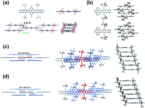 | ||
| Fig. 8 (a) Top: Single-crystal structures of 8 (left: top view, right: side view), bottom: molecular stacking patterns of 8 (left: side view perpendicular to the long axis of the azaacene core; right: side view along the long axis of the azaacene core). (b) X-ray structures and packing of 22b (top) and 22a (bottom). (c) Solid-state structures of 28a. (d) Solid-state structures of 28b. (a) is reprinted with permission from ref. 39. Copyright 2016, Wiley-VCH. (b) is reprinted with permission from ref. 72. Copyright 2016, Wiley-VCH. (c) is reprinted with permission from ref. 45. Copyright 2015, Wiley-VCH. | ||
4. Applications
The conjugation length, the number of sp2 N atoms, and their positions on the backbone endow azaacenes with various photo-electrical properties, which makes them excellent candidates for different organic semiconductor devices. As a typical representative, azapentacenes have been extensively studied in OFETs as p-type, ambipolar and n-type semiconductors with excellent performance. However, research on the application of azaacenes with more than five linearly-fused rings is not as common as for azapentacenes. The research on these materials is mainly focused on phototransistors and OFETs, where there is plenty of room left to improve the device performance.The 19-single-crystal-based organic phototransistor operates well under the photoconductive effect in the range of 40–130 mW cm−2; the current (IDS) is linearly related to the light intensity without any gate voltage27 (Fig. 9a). At a specific drain–source voltage, the concentration of charge carriers and IDS showed good dependence on the light intensity, namely, the output current increased sharply when the light intensity was raised (Fig. 9b). The dynamic photo response behaviour showed that devices based on crystals of 19 can be used as switches with an ON/OFF ratio of ∼102 and good stability (Fig. 9c and d). All results indicate that single crystals of 19 can be used as active components in phototransistors for photodetection or light control switches. The photoelectrochemical behaviour was also used to study the electronic properties of 7 and 8; the repeatable anodic (positive) photocurrent showed that both compounds performed as n-type semiconductors39 (Fig. 9e and g), which was also confirmed by the positive slopes of Mott–Schottky measurements. According to Fig. 9f and h, the flat-band potentials of 7 and 8 can be obtained at about 0.085 and 0.11 V versus reversible hydrogen electrode, respectively.
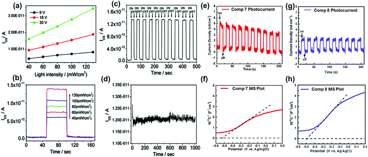 | ||
| Fig. 9 (a) Dependence of IDS on light intensity at specific voltages of 19. (b) Dependence of IDS on different input light intensities of 19. (c) Time dependence of the dynamic photo response behaviour of 19 crystals upon irradiation with 40 mW cm−2 white light. (d) Stability of 19 single crystal-based phototransistors. Zero-bias photocurrent responses of 7 (e) and 8 (g) under chopped AM 1.5 G light illumination. Mott–Schottky plots of 7 (f) and 8 (h) measured at a frequency of 1000 Hz. The flat-band potentials of 7 and 8 are indicated by the intercept of the dashed lines. (a)–(d) are reprinted with permission from ref. 27. Copyright 2012, American Chemical Society. (e) and (f) are reproduced with permission from ref. 39. Copyright 2016, Wiley-VCH. | ||
OFETs are another important application for larger azaacenes. Organic thin film transistors (OTFTs) with a bottom-gate, top-contact (BGTC) device structure were fabricated and characterized to evaluate the potential of 2 and 3 for electronic applications.52 Compound 2 gave the larger mobility (2.5 × 10⁻³ cm2 V−1 s−1) whilst a mobility of 7 × 10⁻⁵ cm2 V−1 s−1 is found in the methyl-substituted compound 3 (Fig. 10a and b). This indicates that the methyl groups at the molecular periphery had a significant effect on the charge transport. The possible reasons for this difference between them are manifold, including different orientations of the molecules relative to the substrate surface, grain size, and charge transfer rate. BGTC OFETs were also fabricated to investigate the charge transport properties of 16.55 The spin-coated film showed an almost amorphous morphology because of the poor polycrystalline nature, resulting in a low hole transport property with an average mobility of μh = 8.2 × 10⁻⁵ cm2 V−1 s−1. For comparison, the authors also fabricated single-crystal-based OFETs and the mobility increased by two orders of magnitude (μh = 8.1 × 10⁻³ cm2 V−1 s−1, Fig. 10c). For compound 31b, the OFETs were fabricated using a bottom-contact top-gate (BCTG) architecture.5431b exhibited a highest electron mobility of 8.1 × 10⁻⁴ cm2 V−1 s−1, as expected from the low LUMO level. The spin-coated active layer showed a polycrystalline nature and small domain size (a few micrometres), resulting in relatively low charge carrier mobility. However, other parameters of these transistors, such as negligible hysteresis, linear injection behaviour, moderate on/off ratios (>103) and low threshold voltages (Vth = −(0.6 ± 1.2) V), are good. Moreover, ambipolar transport was observed (μh ≈ 2 × 10⁻⁴ cm2 V−1 s−1) at higher drain voltages. Different from the above-mentioned compounds, the active layers of OFETs based on 22a and 22b were fabricated through vacuum deposition.72
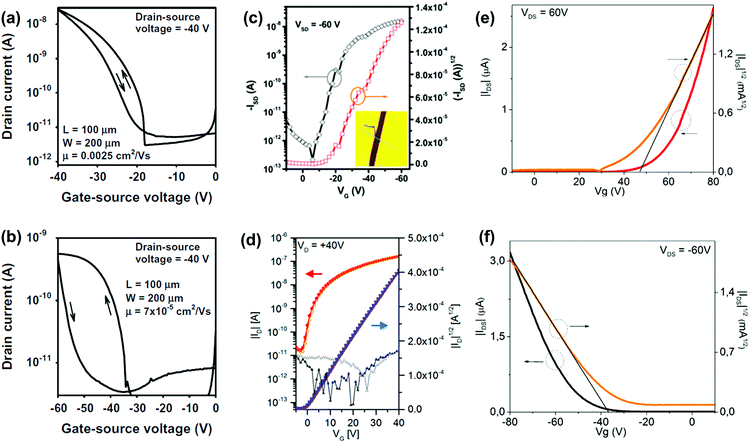 | ||
| Fig. 10 Transfer (IDvs. VGS) characteristics of the OTFTs based on 2 (a) and 3 (b). (c) Representative transfer of single crystal field effect transistors based on 16 with a BCTG geometry; the inset is the microscopy image of a real compound 16 single crystal organic field effect transistor fabricated using the “organic ribbon mask technique”. (W = 1.47 μm, L = 5.08 μm, μh = 8.1 × 10⁻³ cm2 V−1 s−1, Ion/Ioff = 104, VT = −19 V.) (d) Transfer characteristic of 31b in a BCTG FET (W = 1000 μm, L = 10 μm) at VD = 40 V; gate leakage in the background; filled symbols, forward; open symbols, backward sweep. Representative transfer and square root of the absolute values of current as a function of gate potential of thin films 22a (e) and 22b (f). (a) and (b) are reprinted with permission from ref. 52. Copyright 2015, Elsevier B.V. (c) and (d) are reprinted with permission from ref. 55. Copyright 2017, American Chemical Society. (e) and (f) are reprinted with permission from ref. 72. Copyright 2016, American Chemical Society. | ||
The thin films of 22a showed a typical n-type behaviour because of the four N atoms introduced in the aromatic skeleton. The best electron mobility (μe) was 6.04 × 10⁻⁴ cm2 V−1 s−1 with an on/off ratio in the range of 102. In contrast, films of 22b with fewer N atoms in the aromatic skeleton showed totally different charge transport behaviours. 22b is a typical p-type semiconductor with a best hole mobility (μh) of 4.30 × 10⁻⁴ cm2 V−1 s−1 and a moderate on/off ratio in the range of 101. The thin films of 22a and 22b transport different types of carriers, which can be attributed to the intrinsic stabilization of the HOMO and LUMO caused by the differences of N atoms in the backbone. The LUMO of 22a with two additional N atoms is aligned to a greater extent with the Fermi energy of gold, which facilitated electron injection. For the film of 22b, its HOMO matches well with the Fermi level of gold electrodes, which can facilitate hole injection.
5. Conclusions
In this review, we summarized the synthetic routes, the relationships between the molecular structure and single crystal stacking, and the device applications of larger azaacenes (n ≥ 6). Although these molecules have already shown some good performance in devices, there are still some limitations and challenges: (i) most larger azaacenes are based on pyrene units, thus, the development of new building blocks to construct larger azaacenes is necessary; (ii) as the conjugated skeleton extends, suitable single crystals for structural analysis become more and more difficult to obtain; and (iii) the applications of azaacenes are limited to photo and electrical devices, and their magnetic or other unknown properties are rarely reported. Thus, we believe that the summary of synthetic methods could provide some new ideas for the design and synthesis of new higher azaacenes; the elaboration of the relationships between the molecular structure and single crystal stacking could enable researchers to create novel higher azaacenes with the desired molecular packing model; and the diversification of higher azaacenes could further extend their applications in other fields and enhance their device performance.Conflicts of interest
There are no conflicts to declare.Acknowledgements
Q. Z. acknowledges financial support from AcRF Tier 1 (RG 111/17, RG 2/17, RG 114/16, RG 113/18) and Tier 2 (MOE 2017-T2-1-021 and MOE 2018-T2-1-070), Singapore. QZ is also thankful for the funding support from State Key Laboratory of Supramolecular Structure and Materials, Jilin University, P. R. China (sklssm2019036).Notes and references
- F. Kummer and H. Zimmermann, Über die Elektronenspektren linearer Diaza- und Tetraaza-Acene, Ber. Bunsen-Ges., 1967, 71, 1119–1126 CAS.
- Q. Miao, T.-Q. Nguyen, T. Someya, G. B. Blanchet and C. Nuckolls, Synthesis, Assembly, and Thin Film Transistors of Dihydrodiazapentacene:
![[thin space (1/6-em)]](https://www.rsc.org/images/entities/char_2009.gif) An Isostructural Motif for Pentacene, J. Am. Chem. Soc., 2003, 125, 10284–10287 CrossRef CAS PubMed.
An Isostructural Motif for Pentacene, J. Am. Chem. Soc., 2003, 125, 10284–10287 CrossRef CAS PubMed. - A. L. Appleton, S. M. Brombosz, S. Barlow, J. S. Sears, J. L. Bredas, S. R. Marder and U. H. Bunz, Effects of Electronegative Substitution on the Optical and Electronic Properties of Acenes and Diazaacenes, Nat. Commun., 2010, 1, 91 CrossRef PubMed.
- J. U. Engelhart, B. D. Lindner, O. Tverskoy, F. Rominger and U. H. Bunz, Partially Fluorinated Tetraazaacenes by Nucleophilic Aromatic Substitution, J. Org. Chem., 2013, 78, 10832–10839 CrossRef CAS PubMed.
- M. Muller, H. Reiss, O. Tverskoy, F. Rominger, J. Freudenberg and U. H. F. Bunz, Stabilization by Benzannulation: Butterfly Azaacenes, Chem. – Eur. J., 2018, 24, 12801–12805 CrossRef PubMed.
- J. Li, P. Li, J. Wu, J. Gao, W. W. Xiong, G. Zhang, Y. Zhao and Q. Zhang, [4+2] Cycloaddition Reaction to Approach Diazatwistpentacenes: Synthesis, Structures, Physical Properties, and Self-Assembly, J. Org. Chem., 2014, 79, 4438–4445 CrossRef CAS PubMed.
- U. H. Bunz and J. U. Engelhart, The Palladium Way to N-Heteroacenes, Chem. – Eur. J., 2016, 22, 4680–4689 CrossRef CAS PubMed.
- S. Miao, A. L. Appleton, N. Berger, S. Barlow, S. R. Marder, K. I. Hardcastle and U. H. Bunz, 6,13-Diethynyl-5,7,12,14-tetraazapentacene, Chem. – Eur. J., 2009, 15, 4990–4993 CrossRef CAS PubMed.
- Y. Y. Liu, C. L. Song, W. J. Zeng, K. G. Zhou, Z. F. Shi, C. B. Ma, F. Yang, H. L. Zhang and X. Gong, High and Balanced Hole and Electron Mobilities from Ambipolar Thin-Film Transistors Based on Nitrogen-Containing Oligoacences, J. Am. Chem. Soc., 2010, 132, 16349–16351 CrossRef CAS PubMed.
- Z. Liang, Q. Tang, R. Mao, D. Liu, J. Xu and Q. Miao, The Position of Nitrogen in N-Heteropentacenes Matters, Adv. Mater., 2011, 23, 5514–5518 CrossRef CAS PubMed.
- Z. Liang, Q. Tang, J. Xu and Q. Miao, Soluble and Stable N-Heteropentacenes with High Field-Effect Mobility, Adv. Mater., 2011, 23, 1535–1539 CrossRef CAS PubMed.
- C. L. Song, C. B. Ma, F. Yang, W. J. Zeng, H. L. Zhang and X. Gong, Synthesis of Tetrachloro-azapentacene as an Ambipolar Organic Semiconductor with High and Balanced Carrier Mobilities, Org. Lett., 2011, 13, 2880–2883 CrossRef CAS PubMed.
- K. Goto, R. Yamaguchi, S. Hiroto, H. Ueno, T. Kawai and H. Shinokubo, Intermolecular Oxidative Annulation of 2-Aminoanthracenes to Diazaacenes and Aza[7]helicenes, Angew. Chem., Int. Ed., 2012, 51, 10333–10336 CrossRef CAS PubMed.
- Z. Cai, M. A. Awais, N. Zhang and L. Yu, Exploration of Syntheses and Functions of Higher Ladder-type π-Conjugated Heteroacenes, Chem, 2018, 4, 2538–2570 CAS.
- M. Chu, J. X. Fan, S. Yang, D. Liu, C. F. Ng, H. Dong, A. M. Ren and Q. Miao, Halogenated Tetraazapentacenes with Electron Mobility as High as 27.8 cm2 V−1 s−1 in Solution-Processed n-Channel Organic Thin-Film Transistors, Adv. Mater., 2018, 30, 1803467 CrossRef PubMed.
- M. B. Casu, P. Imperia, S. Schrader, B. Falk, M. Jandke and P. Strohriegl, Ultraviolet Photoelectron Spectroscopy on New Heterocyclic Materials for Multilayer Organic Light Emitting Diodes, Synth. Met., 2001, 124, 79–81 CrossRef CAS.
- C. J. Tonzola, M. M. Alam, W. Kaminsky and S. A. Jenekhe, New n-Type Organic Semiconductors:
![[thin space (1/6-em)]](https://www.rsc.org/images/entities/char_2009.gif) Synthesis, Single Crystal Structures, Cyclic Voltammetry, Photophysics, Electron Transport, and Electroluminescence of a Series of Diphenylanthrazolines, J. Am. Chem. Soc., 2003, 125, 13548–13558 CrossRef CAS PubMed.
Synthesis, Single Crystal Structures, Cyclic Voltammetry, Photophysics, Electron Transport, and Electroluminescence of a Series of Diphenylanthrazolines, J. Am. Chem. Soc., 2003, 125, 13548–13558 CrossRef CAS PubMed. - G. Li, A. P. Abiyasa, J. Gao, Y. Divayana, W. Chen, Y. Zhao, X. W. Sun and Q. Zhang, Synthesis and Properties of a Diazopentacene Analogue, Asian J. Org. Chem., 2012, 1, 346–351 CrossRef CAS.
- B. D. Lindner, Y. Zhang, S. Höfle, N. Berger, C. Teusch, M. Jesper, K. I. Hardcastle, X. Qian, U. Lemmer, A. Colsmann, U. H. F. Bunz and M. Hamburger, N-Fused Quinoxalines and Benzoquinoxalines as Attractive Emitters for Organic Light Emitting Diodes, J. Mater. Chem. C, 2013, 1, 5718–5724 RSC.
- J. Li, F. Yan, J. Gao, P. Li, W.-W. Xiong, Y. Zhao, X. W. Sun and Q. Zhang, Synthesis, Physical Properties and OLED Performance of Azatetracenes, Dyes Pigm., 2015, 112, 93–98 CrossRef CAS.
- M. Tadokoro, S. Yasuzuka, M. Nakamura, T. Shinoda, T. Tatenuma, M. Mitsumi, Y. Ozawa, K. Toriumi, H. Yoshino, D. Shiomi, K. Sato, T. Takui, T. Mori and K. Murata, A High-Conductivity Crystal Containing a Copper(I) Coordination Polymer Bridged by the Organic Acceptor TANC, Angew. Chem., Int. Ed., 2006, 45, 5144–5147 CrossRef CAS PubMed.
- S. Miao, C. G. Bangcuyo, M. D. Smith and U. H. F. Bunz, Derivatives of Octaethynylphenazine and Hexaethynylquinoxaline, Angew. Chem., Int. Ed., 2006, 118, 677–681 CrossRef.
- J. J. Bryant, Y. Zhang, B. D. Lindner, E. A. Davey, A. L. Appleton, X. Qian and U. H. F. Bunz, Derivatives of Octaethynylphenazine and Hexaethynylquinoxaline, J. Org. Chem., 2012, 77, 7479–7486 CrossRef CAS PubMed.
- G. Li, Y. Wu, J. Gao, J. Li, Y. Zhao and Q. Zhang, Synthesis, Physical Properties, and Anion Recognition of Two Novel Larger Azaacenes: Benzannelated Hexazaheptacene and Benzannelated N,N′-Dihydrohexazaheptacene, Chem. – Asian J., 2013, 8, 1574–1578 CrossRef CAS PubMed.
- G. Li, J. Gao and Q. Zhang, Synthesis, Characterization, and Sensing Behavior of an N-Heteropentacene, Asian J. Org. Chem., 2014, 3, 203–208 CrossRef CAS.
- P.-Y. Gu, Z. Wang and Q. Zhang, Azaacenes as Active Elements for Sensing and Bio Applications, J. Mater. Chem. B, 2016, 4, 7060–7074 RSC.
- Y. Wu, Z. Yin, J. Xiao, Y. Liu, F. Wei, K. J. Tan, C. Kloc, L. Huang, Q. Yan, F. Hu, H. Zhang and Q. Zhang, Crystal Structure and Phototransistor Behavior of N-Substituted Heptacence, ACS Appl. Mater. Interfaces, 2012, 4, 1883–1886 CrossRef CAS PubMed.
- Q. Zhang, J. Xiao, Z. Yin, H. M. Duong, F. Qiao, F. Boey, X. Hu, H. Zhang and F. Wudl, Synthesis, Characterization, and Physical Properties of a Conjugated Heteroacene: 2-Methyl-1,4,6,7,8,9-hexaphenylbenz(g)isoquinolin-3(2H)-one (BIQ), Chem. – Asian J., 2011, 6, 856–862 CrossRef CAS PubMed.
- P.-Y. Gu, N. Wang, C. Wang, Y. Zhou, G. Long, M. Tian, W. Chen, X. W. Sun, M. G. Kanatzidis and Q. Zhang, Pushing up the Efficiency of Planar Perovskite Solar Cells to 18.2% with Organic Small Molecules as the Electron Transport Layer, J. Mater. Chem. A, 2017, 5, 7339–7344 RSC.
- A. A. Said, J. Xie and Q. Zhang, Recent Progress in Organic Electron Transport Materials in Inverted Perovskite Solar Cells, Small, 2019, 15, 1900854 CrossRef PubMed.
- P. Y. Gu, N. Wang, A. Wu, Z. Wang, M. Tian, Z. Fu, X. W. Sun and Q. Zhang, An Azaacene Derivative as Promising Electron-Transport Layer for Inverted Perovskite Solar Cells, Chem. – Asian J., 2016, 11, 2135–2138 CrossRef CAS PubMed.
- N. Wang, K. Zhao, T. Ding, W. Liu, A. S. Ahmed, Z. Wang, M. Tian, X. W. Sun and Q. Zhang, Improving Interfacial Charge Recombination in Planar Heterojunction Perovskite Photovoltaics with Small Molecule as Electron Transport Layer, Adv. Energy Mater., 2017, 7, 1700522 CrossRef.
- G. Li, K. Zheng, C. Wang, K. S. Leck, F. Hu, X. W. Sun and Q. Zhang, Synthesis and Nonvolatile Memory Behaviors of Dioxatetraazapentacene Derivatives, ACS Appl. Mater. Interfaces, 2013, 5, 6458–6462 CrossRef CAS PubMed.
- P. Y. Gu, F. Zhou, J. Gao, G. Li, C. Wang, Q. F. Xu, Q. Zhang and J. M. Lu, Synthesis, Characterization, and Nonvolatile Ternary Memory Behavior of a Larger Heteroacene with Nine Linearly Fused Rings and Two Different Heteroatoms, J. Am. Chem. Soc., 2013, 135, 14086–14089 CrossRef CAS PubMed.
- C. Wang, J. Wang, P.-Z. Li, J. Gao, S. Y. Tan, W.-W. Xiong, B. Hu, P. S. Lee, Y. Zhao and Q. Zhang, Synthesis, Characterization, and Non-Volatile Memory Device Application of an N-Substituted Heteroacene, Chem. – Asian J., 2014, 9, 779–783 CrossRef CAS PubMed.
- C. Wang, B. Hu, J. Wang, J. Gao, G. Li, W. W. Xiong, B. Zou, M. Suzuki, N. Aratani, H. Yamada, F. Huo, P. S. Lee and Q. Zhang, Rewritable Multilevel Memory Performance of a Tetraazatetracene Donor–Acceptor Derivative with Good Endurance, Chem. – Asian J., 2015, 10, 116–119 CrossRef PubMed.
- P.-Y. Gu, J. Gao, C.-J. Lu, W. Chen, C. Wang, G. Li, F. Zhou, Q.-F. Xu, J.-M. Lu and Q. Zhang, Synthesis of Tetranitro-Oxacalix[4]Arene with Oligoheteroacene Groups and Its Nonvolatile Ternary Memory Performance, Mater. Horiz., 2014, 1, 446–451 RSC.
- G. Li, J. Miao, J. Cao, J. Zhu, B. Liu and Q. Zhang, Preparation and Photoelectrochemical Behavior of 1,4,6,8,11,13-Hexazapentacene (HAP), Chem. Commun., 2014, 50, 7656–7658 RSC.
- Z. Wang, J. Miao, G. Long, P. Gu, J. Li, N. Aratani, H. Yamada, B. Liu and Q. Zhang, Full Characterization and Photoelectrochemical Behavior of Pyrene-fused Octaazadecacene and Tetraazaoctacene, Chem. – Asian J., 2016, 11, 482–485 CrossRef CAS PubMed.
- P.-Y. Gu, Z. Wang, F.-X. Xiao, Z. Lin, R. Song, Q.-F. Xu, J.-M. Lu, B. Liu and Q. Zhang, An Ambipolar Azaacene as a Stable Photocathode for Metal-Free Light-Driven Water Reduction, Mater. Chem. Front., 2017, 1, 495–498 RSC.
- J. Lee, A. J. Kalin, T. Yuan, M. Al-Hashimi and L. Fang, Fully Conjugated Ladder Polymers, Chem. Sci., 2017, 8, 2503–2521 RSC.
- H. Qu and C. Chi, Synthetic Chemistry of Acenes and Heteroacenes, Curr. Org. Chem., 2010, 14, 2070–2108 CrossRef CAS.
- J. Li, S. Chen, Z. Wang and Q. Zhang, Pyrene-fused Acenes and Azaacenes: Synthesis and Applications, Chem. Rec., 2016, 16, 1518–1530 CrossRef CAS PubMed.
- B. D. Lindner, J. U. Engelhart, O. Tverskoy, A. L. Appleton, F. Rominger, A. Peters, H. J. Himmel and U. H. Bunz, Stable Hexacenes Through Nitrogen Substitution, Angew. Chem., Int. Ed., 2011, 50, 8588–8591 CrossRef CAS PubMed.
- J. U. Engelhart, B. D. Lindner, M. Schaffroth, D. Schrempp, O. Tverskoy and U. H. Bunz, Substituted Tetraaza- and Hexaazahexacenes and their N,N′-Dihydro Derivatives: Syntheses, Properties, and Structures, Chem. – Eur. J., 2015, 21, 8121–8129 CrossRef CAS PubMed.
- J. U. Engelhart, B. D. Lindner, O. Tverskoy, F. Rominger and U. H. Bunz, Pd-Catalyzed Coupling of Non-Activated Dibromoarenes to 2,3-Diaminoarenes: Formation of N,N′-Dihydropyrazines, Chem. – Eur. J., 2013, 19, 15089–15092 CrossRef CAS PubMed.
- J. U. Engelhart, O. Tverskoy and U. H. Bunz, A Persistent Diazaheptacene Derivative, J. Am. Chem. Soc., 2014, 136, 15166–15169 CrossRef CAS PubMed.
- A. Mateo-Alonso, Pyrene-fused Pyrazaacenes: From Small Molecules to Nanoribbons, Chem. Soc. Rev., 2014, 43, 6311–6324 RSC.
- X. Feng, J.-Y. Hu, C. Redshaw and T. Yamato, Functionalization of Pyrene To Prepare Luminescent Materials—Typical Examples of Synthetic Methodology, Chem. – Eur. J., 2016, 22, 11898–11916 CrossRef CAS PubMed.
- H. Vollmann, H. Becker, M. Corell and H. Streeck, Beiträge zur Kenntnis des Pyrens und seiner Derivate, Justus Liebigs Ann. Chem., 1937, 531, 1–159 CrossRef CAS.
- J. Hu, D. Zhang and F. W. Harris, Ruthenium(III) Chloride Catalyzed Oxidation of Pyrene and 2,7-Disubstitued Pyrenes:
![[thin space (1/6-em)]](https://www.rsc.org/images/entities/char_2009.gif) An Efficient, One-Step Synthesis of Pyrene-4,5-diones and Pyrene-4,5,9,10-tetraones, J. Org. Chem., 2005, 70, 707–708 CrossRef CAS PubMed.
An Efficient, One-Step Synthesis of Pyrene-4,5-diones and Pyrene-4,5,9,10-tetraones, J. Org. Chem., 2005, 70, 707–708 CrossRef CAS PubMed. - B. Wex, A. a. O. El-Ballouli, A. Vanvooren, U. Zschieschang, H. Klauk, J. A. Krause, J. Cornil and B. R. Kaafarani, Crystalline TQPP as p-Type Semiconductor: X-Ray Crystallographic Investigation, OTFT Device, and Computational Analysis of Transport Properties, J. Mol. Struct., 2015, 1093, 144–149 CrossRef CAS.
- B. Kohl, F. Rominger and M. Mastalerz, A Pyrene-Fused N-Heteroacene with Eleven Rectilinearly Annulated Aromatic Rings, Angew. Chem., Int. Ed., 2015, 54, 6051–6056 CrossRef CAS PubMed.
- A. H. Endres, M. Schaffroth, F. Paulus, H. Reiss, H. Wadepohl, F. Rominger, R. Kramer and U. H. Bunz, Coronene-Containing N-Heteroarenes: 13 Rings in a Row, J. Am. Chem. Soc., 2016, 138, 1792–1795 CrossRef CAS PubMed.
- P. Y. Gu, Z. R. Wang, G. F. Liu, H. Y. Yao, Z. L. Wang, Y. Li, J. Zhu, S. Z. Li and Q. Zhang, Synthesis, Full Characterization, and Field Effect Transistor Behavior of a Stable Pyrene-Fused N-Heteroacene with Twelve Linearly Annulated Six-Membered Rings, Chem. Mater., 2017, 29, 4172–4175 CrossRef CAS.
- Z. Wang, P. Gu, G. Liu, H. Yao, Y. Wu, Y. Li, G. Rakesh, J. Zhu, H. Fu and Q. Zhang, A Large Pyrene-Fused N-Heteroacene: Fifteen Aromatic Six-Membered Rings Annulated in One Row, Chem. Commun., 2017, 53, 7772–7775 RSC.
- B. Fraboni, A. Fraleoni-Morgera, Y. Geerts, A. Morpurgo and V. Podzorov, Organic Single Crystals: An Essential Step to New Physics and Higher Performances of Optoelectronic Devices, Adv. Funct. Mater., 2016, 26, 2229–2232 CrossRef CAS.
- Q. Miao, N-Heteropentacenes and N-Heteropentacenequinones: From Molecules to Semiconductors, Synlett, 2012, 326–336 CrossRef CAS.
- Q. Miao, Ten Years of N-Heteropentacenes as Semiconductors for Organic Thin-Film Transistors, Adv. Mater., 2014, 26, 5541–5549 CrossRef CAS PubMed.
- J. K. Stille and E. L. Mainen, Thermally Stable Ladder Polyquinoxalines, Macromolecules, 1968, 1, 36–42 CrossRef CAS.
- B. Kohl, M. V. Bohnwagner, F. Rominger, H. Wadepohl, A. Dreuw and M. Mastalerz, Attractive Dispersion Interactions Versus Steric Repulsion of tert-Butyl groups in the Crystal Packing of a D3h-Symmetric Tris(quinoxalinophenanthrophenazine), Chem. – Eur. J., 2016, 22, 646–655 CrossRef CAS PubMed.
- P. K. Sahoo, C. Giri, T. S. Haldar, R. Puttreddy, K. Rissanen and P. Mal, Mechanochemical Synthesis, Photophysical Properties, and X-ray Structures of N-Heteroacenes, Eur. J. Org. Chem., 2016, 1283–1291 CrossRef CAS.
- B. Gao, M. Wang, Y. Cheng, L. Wang, X. Jing and F. Wang, Pyrazine-Containing Acene-Type Molecular Ribbons with up to 16 Rectilinearly Arranged Fused Aromatic Rings, J. Am. Chem. Soc., 2008, 130, 8297–8306 CrossRef CAS PubMed.
- S. Miao, J. Ji, L. Zhu, C. Klug and M. Smith, Synthesis of Large Pyrene-Fused Azaacenes, Synthesis, 2015, 871–874 CrossRef.
- X. Feng, F. Iwanaga, J. Y. Hu, H. Tomiyasu, M. Nakano, C. Redshaw, M. R. Elsegood and T. Yamato, An Efficient Approach to the Synthesis of Novel Pyrene-Fused Azaacenes, Org. Lett., 2013, 15, 3594–3597 CrossRef CAS PubMed.
- C.-Z. Wang, X. Feng, M. R. J. Elsegood, T. G. Warwick, S. J. Teat, C. Redshaw, Y.-S. Bi and T. Yamato, Pyrene-Fused Pyrazaacenes with Eight Rectilinearly Arranged Aromatic Rings, Asian J. Org. Chem., 2018, 7, 1–7 CrossRef CAS.
- S. More, R. Bhosale, S. Choudhary and A. Mateo-Alonso, Versatile 2,7-Substituted Pyrene Synthons for the Synthesis of Pyrene-Fused Azaacenes, Org. Lett., 2012, 14, 4170–4173 CrossRef CAS PubMed.
- S. More, S. Choudhary, A. Higelin, I. Krossing, M. Melle-Franco and A. Mateo-Alonso, Twisted Pyrene-Fused Azaacenes, Chem. Commun., 2014, 50, 1976–1979 RSC.
- A. Mateo-Alonso, N. Kulisic, G. Valenti, M. Marcaccio, F. Paolucci and M. Prato, Facile Synthesis of Highly Stable Tetraazaheptacene and Tetraazaoctacene Dyes, Chem. – Asian J., 2010, 5, 482–485 CrossRef CAS PubMed.
- B. Kohl, F. Rominger and M. Mastalerz, Rigid π-Extended Triptycenes via a Hexaketone Precursor, Org. Lett., 2014, 16, 704–707 CrossRef CAS PubMed.
- E. C. Rüdiger, M. Müller, S. Koser, F. Rominger, J. Freudenberg and U. H. F. Bunz, Dibenzohexacene: Stabilization Through Additional Clar Sextets, Chem. – Eur. J., 2018, 24, 1036–1040 CrossRef PubMed.
- G. Antonicelli, C. Gozalvez, A. Atxabal, M. Melle-Franco, L. E. Hueso and A. Mateo-Alonso, Org. Lett., 2016, 18, 4694–4697 CrossRef CAS PubMed.
- B. D. Lindner, J. U. Engelhart, O. Tverskoy, A. L. Appleton, F. Rominger, A. Peters, H. J. Himmel and U. H. F. Bunz, Stable Hexacenes through Nitrogen Substitution, Angew. Chem., Int. Ed., 2011, 50, 8588–8591 CrossRef CAS.
- J. U. Engelhart, B. D. Lindner, M. Schaffroth, D. Schrempp, O. Tverskoy and U. H. F. Bunz, Substituted Tetraaza- and Hexaazahexacenes and their N,N-Dihydro Derivatives: Syntheses, Properties, and Structures, Chem. – Eur. J., 2015, 21, 8121–8129 CrossRef CAS PubMed.
- A. H. Endres, M. Schaffroth, F. Paulus, H. Reiss, H. Wadepohl, F. Rominger, R. Kramer and U. H. F. Bunz, Coronene-Containing N-Heteroarenes: 13 Rings in a Row, J. Am. Chem. Soc., 2016, 138, 1792–1795 CrossRef CAS PubMed.
- M. Solà, Forty Years of Clar's Aromatic π-Sextet Rule, Front. Chem., 2013, 1, 1–8 Search PubMed.
| This journal is © the Partner Organisations 2020 |


