 Open Access Article
Microfluidically fabricated pH-responsive anionic amphiphilic microgels for drug release
B.
Lu
a,
M. D.
Tarn
a,
N.
Pamme
*a and
T. K.
Georgiou
*b
aDepartment of Chemistry, University of Hull, HU6 7RX, Hull, UK. E-mail: n.pamme@hull.ac.uk
bDepartment of Materials, Imperial College London, SW7 2AZ, London, UK. E-mail: t.georgiou@imperial.ac.uk
First published on 29th December 2015
Abstract
Amphiphilic microgels of different composition based on the hydrophilic, pH-responsive acrylic acid (AA) and the hydrophobic, non-ionic n-butyl acrylate (BuA) were synthesised using a lab-on-a-chip device. Hydrophobic droplets were generated via a microfluidic platform that contained a protected form of AA, BuA, the hydrophobic crosslinker, ethylene glycol dimethacrylate (EGDMA), and a free radical initiator in an organic solvent. These hydrophobic droplets were photopolymerised within the microfluidic channels and subsequently hydrolysed, enabling an integrated platform for the rapid, automated, and in situ production of anionic amphiphilic microgels. The amphiphilic microgels did not feature the conventional core–shell structure but were instead based on random amphiphilic copolymers of AA and BuA and hydrophobic crosslinks. Due to their amphiphilic nature they were able to encapsulate and deliver both hydrophobic and hydrophilic moieties. The model drug delivery and the swelling ability of the microgels were influenced by the pH of the surrounding aqueous solution and the hydrophobic content of the microgels.
Introduction
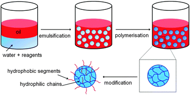
Three-dimensionally crosslinked polymer networks with sizes ranging from 0.1 to 100 μm are often referred to as gel particles or microgels. These particles, which are usually dispersed in a solvent, have many exciting biomedical applications such as in drug delivery,1–10 tissue engineering,2 and biosensing,11 as well as applications in the oil industry,12 organic dye removal,13,14 coatings15 and the food industry.16 If the microgels are hydrophilic then they can be dispersed in aqueous solvents, while if they are hydrophobic they are usually called latex particles and cannot be dispersed in aqueous media. Gel particles/microgels that are amphiphilic, in other words containing both hydrophilic and hydrophobic groups, offer the advantage that they can be dispersed in both aqueous and non-aqueous media as well as encapsulate and release both hydrophilic and hydrophobic moieties.Amphiphilic microgels, though, are challenging to fabricate because most of the production methods, such as conventional emulsion templating, involve the formation of droplets in an immiscible continuous phase, as shown in Fig. 1. The droplets contain pre-gels or polymerisable reagents that are later reacted to form the microgel. Thus, when fabricating hydrophilic microgels, the hydrophilic reagents are dispersed in aqueous droplets while the continuous phase (CP) is an organic solvent/oil in which the reagents have reduced or no solubility. However, if the CP is aqueous then the hydrophilic reagent will diffuse from the droplets to the surrounding CP, and vice versa. Likewise, if the CP is based on oil or an organic solvent, then hydrophobic reagents would diffuse from the droplets to the CP. Thus, amphiphilic microgels are usually prepared using post-modifications1,4,7,17–21 and/or multi-step procedures.6,22 Typically, hydrophilic microgels are initially fabricated and then modified to produce amphiphilic microgels by covalently or electrostatically binding amphiphilic or hydrophobic moieties.1,4,7,18–21 However this results in a “core–shell” microgel structure since the attachment happens mostly on the outer area/surface of the microgel and the hydrophobic groups are never within the elastic chain (the chain between the crosslinks) but instead grafted on the chain.
The application of microfluidic platforms23 for the production of gel particles offers the advantages of (i) generating droplets,24,25 and consequently microgels, of narrower size distribution and (ii) the ability to tailor the size of the droplets/microgels by varying the applied flow rates of the droplet dispersed phase (DP) and the CP.16,26–29 Furthermore, when using a microfluidic device, reactions can be performed on the droplets directly within the microchannels, or immediately following off-chip collection of the droplets, thereby enabling the polymerisation of some relatively unstable and easily hydrolysed reagents. For example, (meth)acrylic monomers tend to hydrolyse to (meth)acrylic acid when in contact with water,30 so they cannot easily be dispersed in water or be polymerised in water to produce amphiphilic microgels.
Our previous study31 was, to the best of our knowledge, the first in which amphiphilic microgels were produced using a lab-on-a-chip device. Specifically, amphiphilic microgels based on a hydrophilic monomer and a hydrophobic crosslinker were fabricated by the formation of precursor droplets within the microchannels and their subsequent collection and off-chip polymerisation. In this study, we have designed a new microfluidic chip with a long and deep serpentine channel that allowed the droplets to travel within the chip itself for a longer period of time, enabling their rapid and in situ polymerisation in an automated fashion. This new platform offers the advantage of ensuring even narrower size distributions of the droplets without risking their coalescence or getting destabilisation. In our previous study, anionic amphiphilic microgels of varying crosslinking densities, which was proportional to the hydrophobic content, were fabricated and the effect on the ability of the microgels to swell was investigated, in addition to their capacity to encapsulate and release hydrophobic and hydrophilic moieties used as models drugs.31
In the present study the crosslinking density was kept constant and a hydrophobic monomer (n-butyl acrylate, BuA) was introduced on the elastic chain (the chain between the crosslinks) in order to allow the hydrophobic content to be systematically varied without changing crosslinking density. The crosslinker, ethylene glycol dimethacrylate (EGDMA), was kept the same as in our previous work, as was the hydrophilic monomer, acrylic acid (AA). Since acrylic acid is not soluble in the chloroform dispersed phase into which the BuA and EGDMA were dissolved, the same approach as used in the previous study was employed by which a protected form of AA, specifically tetrahydropyranyl acrylate (THPA), was synthesised in-house and incorporated into the DP for polymerisation. The resulting THPA–BuA–EGDMA microgels were then hydrolysed to deprotect the AA units and thus form anionic amphiphilic AA–BuA–EGDMA microgels. Microgels of varying hydrophobic/hydrophilic (BuA/AA) ratio but with the same crosslinking density were fabricated. The pH responsiveness of the AA based microgels was evaluated by studying their swelling in different aqueous pH solutions. Finally, to demonstrate the amphiphilic nature of the microgels and their potential for drug delivery, the encapsulation and release of both hydrophobic and hydrophilic moieties was investigated using Sudan I and Trypan Blue, respectively, as model drugs.
Experimental
Materials and methods
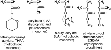
Acrylic acid (AA, 99%), n-butyl acrylate (BuA, 99%), 2,3-dihydro-2H-pyran (DHP, 99%), ethylene glycol dimethacrylate (EGDMA, crosslinker), sodium dodecyl sulfate (SDS), 2,2-diphenyl-1-picrylhydrazyl hydrate (DPPH, free radical inhibitor, 99%), 1-hydroxy-cyclohexyl phenyl ketone (HCPK, 99%, free radical initiator), Sudan I, Trypan Blue, phenothiazine (98%, free radical inhibitor), sulphuric acid, sodium bicarbonate (NaHCO3), sodium sulphate (Na2SO4), hydrochloric acid, sodium hydroxide and basic alumina were purchased from Sigma-Aldrich (Dorset, UK). BuA and EGDMA were passed through a basic alumina column to remove the free radical initiator prior to use. The organic solvent used to prepare the hydrophobic droplets was chloroform (99%), and was purchased from Fisher Scientific (Loughborough, UK). The chemical structures of the main reagents used for microgel fabrication (AA, BuA and EGDMA), including the in-house synthesised monomer (THPA, synthesis described below) are shown in Fig. 2.The next day, once the mixture had cooled, 10 g of NaHCO3 and 40 g of Na2SO4 were added and allowed to stir for 2–3 h. The solids were then filtered out and the monomer mixture was passed through two basic alumina columns (to remove the un-reacted AA, the THPMA monomer yield was ∼60%). The removal of AA was confirmed by 1H NMR. A free radical inhibitor, DPPH, was added into the THPA monomer, which was then stored in the fridge. The THPA was distilled under vacuum prior to use.
Fabrication of microgels
Videos and images of on-chip droplet generation were obtained using a colour CCD camera (MTV-63V1N, Mintron, Taiwan) attached to an inverted microscope (Eclipse Ti, Nikon, UK), with images captured via WinDVD Creator 2 (Corel Ltd, UK) software. Collected microgels were observed either on the same microscope setup, or using a second setup consisting of an upright microscope (BH-2, Olympus, UK), a CCD camera (INFINITYlite, Lumenera) and capture software (Studio Capture, Mettler-Toledo, Inc.). ImageJ freeware was used for the analysis of droplet size and colour intensity.
![[thin space (1/6-em)]](https://www.rsc.org/images/entities/char_2009.gif) :
:![[thin space (1/6-em)]](https://www.rsc.org/images/entities/char_2009.gif) 4 THPA/BuA
4 THPA/BuA![[thin space (1/6-em)]](https://www.rsc.org/images/entities/char_2009.gif) :
:![[thin space (1/6-em)]](https://www.rsc.org/images/entities/char_2009.gif) EGDMA), and 4 wt% of HCPK (free radical photoinitiator). The CP was an aqueous solution of 0.1 wt% SDS, with the concentration of SDS being below the critical micelle concentration.38 During droplet generation optimisation studies, the flow rate of the CP was varied from 0.5 μL min−1 to 5 μL min−1, while the DP flow rate was held at 0.5 μL min−1. Later microgel fabrication was performed at CP and DP flow rates of 2 μL min−1 and 0.5 μL min−1, respectively. These flow rates allowed the droplets to be UV irradiated for 30 min as they passed through the serpentine channel, forming the microgels. One THPA–EGDMA microgel and three THPA–BuA–EGDMA microgels of differing compositions were formed, with molar ratios of 75
EGDMA), and 4 wt% of HCPK (free radical photoinitiator). The CP was an aqueous solution of 0.1 wt% SDS, with the concentration of SDS being below the critical micelle concentration.38 During droplet generation optimisation studies, the flow rate of the CP was varied from 0.5 μL min−1 to 5 μL min−1, while the DP flow rate was held at 0.5 μL min−1. Later microgel fabrication was performed at CP and DP flow rates of 2 μL min−1 and 0.5 μL min−1, respectively. These flow rates allowed the droplets to be UV irradiated for 30 min as they passed through the serpentine channel, forming the microgels. One THPA–EGDMA microgel and three THPA–BuA–EGDMA microgels of differing compositions were formed, with molar ratios of 75![[thin space (1/6-em)]](https://www.rsc.org/images/entities/char_2009.gif) :
:![[thin space (1/6-em)]](https://www.rsc.org/images/entities/char_2009.gif) 0, 49
0, 49![[thin space (1/6-em)]](https://www.rsc.org/images/entities/char_2009.gif) :
:![[thin space (1/6-em)]](https://www.rsc.org/images/entities/char_2009.gif) 21, 35
21, 35![[thin space (1/6-em)]](https://www.rsc.org/images/entities/char_2009.gif) :
:![[thin space (1/6-em)]](https://www.rsc.org/images/entities/char_2009.gif) 35, and 21
35, and 21![[thin space (1/6-em)]](https://www.rsc.org/images/entities/char_2009.gif) :
:![[thin space (1/6-em)]](https://www.rsc.org/images/entities/char_2009.gif) 49 THPA
49 THPA![[thin space (1/6-em)]](https://www.rsc.org/images/entities/char_2009.gif) :
:![[thin space (1/6-em)]](https://www.rsc.org/images/entities/char_2009.gif) BuA, respectively. The polymerised microgels were collected off-chip and then hydrolysed in a solution of 0.01 M HCl solution (pH 2) overnight to produce pH responsive AA–BuA–EGDMA microgels. The hydrolysis was confirmed with FTIR.
BuA, respectively. The polymerised microgels were collected off-chip and then hydrolysed in a solution of 0.01 M HCl solution (pH 2) overnight to produce pH responsive AA–BuA–EGDMA microgels. The hydrolysis was confirmed with FTIR.
Swelling studies in different pH environments
Aqueous solutions of NaOH (1 M) and HCl (1 M) were used to vary the pH of the solution that the AA–BuA–EGDMA microgels were suspended in, from pH 1 to pH 14. These tests were performed in order to study the responsiveness of the microgel particles. The microgels were photographed using the colour CCD camera and microscope setups described previously, with ImageJ used for image analysis. The extent of swelling and shrinking (relative size) was calculated by dividing the microgel diameter at a given pH by their original diameter measured at pH 7.pKa determination
The pKa values of the three synthesised AA–BuA–EGDMA microgels were determined by potentiometric titration. Specifically, 0.02 g of each microgel was dispersed in water, and 1 M NaOH added to increase the pH above 11. The titration was performed by adding 0.05 mL aliquots of 0.1 M HCl and measuring the pH after each addition.Dye encapsulation and release studies
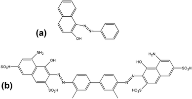
Two types of dye, acting as model drugs, were encapsulated in the microgels via two different methodologies to determine the capability of the microgels to encapsulate and release both hydrophilic and hydrophobic moieties. 1 wt% hydrophobic Sudan I was mixed into the DP prior to droplet formation, hence the dye was already present inside the microgel following droplet generation and polymerisation. 1 wt% hydrophilic Trypan Blue was loaded into already polymerised AA containing microgels in a pH 14 solution by diffusion with sonication for 30 min, before removing the microgels by pipette, adding them to a microscope slide and removing any excess solution. The chemical structures of both dyes are shown in Fig. 4. The model drug release was monitored using the colour camera of the microscopes. In particular, the change in microgel colour intensity over time. Images were taken at regular time intervals (every 1 min or 5 min depending on the rate of release). ImageJ freeware was used for the analysis of the colour intensity.Results and discussion
Droplet generation and polymerisation
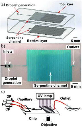
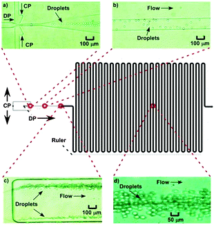
The influence of flow rate on droplet size in the new microfluidic chip design was first investigated by increasing the flow rate of the CP from 0.5 μL min−1 to 5 μL min−1, while the DP flow rate was held at 0.5 μL min−1, allowing droplet diameters to be controlled between 8 μm (volume of 0.3 pL) and 18 μm (3.1 pL) (CV typical ∼9%) (Fig. 5). This enabled far smaller monodisperse droplets to be produced compared to the microfluidic chip design used in the previous study,31 in which droplets of ∼130 μm could be generated with similar CVs to those shown here, while smaller droplets yielded much larger CVs. The smaller droplet sizes in this study were achieved as a result of the much shallower and thinner channel dimensions in the flow focusing section of the chip (Fig. 6a). For amphiphilic microgel fabrication, the flow rates of the CP and DP were 2 μL min−1 and 0.5 μL min−1, respectively, yielding droplets with a volume of 3.1 pL (CV 7%). The droplets then passed through the short serpentine mixing section, with the same dimensions as the flow focusing channels due to their being in the same layer of the fabricated chip, which allowed rapid mixing of the monomers (THPA and BuA) and crosslinker (EGDMA) inside the droplets. Following this, the droplets passed from the 10 μm deep channel (Fig. 6b) to the 60 μm deep serpentine channel (Fig. 6c), where they went from being pancake shaped in the narrow channels to spherical in the deeper channel. Interestingly, as the droplets traversed this shallow serpentine channel they were observed to experience inertial forces,39,40 which focused them to the outer edges of the channel before they entered the deeper channel region (Fig. 6c).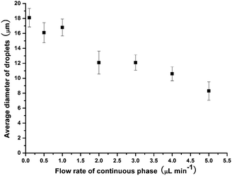 | ||
| Fig. 5 Control of droplet size by varying the flow rate of the aqueous continuous phase, with the dispersed phase flow rate held constant at 0.5 μL min−1. | ||
The dimensions of the large serpentine channel meant that, at the applied flow rates, the droplets were polymerised to THPA–BuA–EGDMA microgels for 30 min as they passed through it (Fig. 6d). These features offered further improvement over the previous chip design31 in which the generated droplets could not be polymerised on-chip due to the extremely short residence time, while the droplets also remained flattened in the chip and only became spherical when collected in a dish for off-chip polymerisation (30 min). Thus, the new chip design and setup enabled integrated, in situ polymerisation of small, monodisperse, spherical microgels, in an essentially automated fashion; a scenario that was not possible with the previous chip setup. This also allowed better microgel size distribution and more accurate polymerisation times without risking the droplets being destabilised and any monomer leaking out of the droplets prior to polymerisation.
The polymerised microgels were collected from the chip outlet, and the THPA groups were deprotected by adding the microgels to a solution of HCl (pH 2) to form AA groups by hydrolysis. The resulting amphiphilic AA–BuA–EGDMA microgels consisted of a hydrophilic AA, hydrophobic BuA and hydrophobic EGDMA crosslinked internal network, whose ratios could be altered by varying the relative amounts of each component in the precursor DP solution.
Microgel fabrication and pH responsiveness studies
Three types of amphiphilic AA–BuA–EDGMA microgels of different compositions, in addition to a AA–EGDMA homopolymer microgel, were successfully fabricated via the microfluidic approach described above. Specifically, the four populations contained different monomer ratios (AA![[thin space (1/6-em)]](https://www.rsc.org/images/entities/char_2009.gif) :
:![[thin space (1/6-em)]](https://www.rsc.org/images/entities/char_2009.gif) BuA) but the same crosslinking density (monomer
BuA) but the same crosslinking density (monomer![[thin space (1/6-em)]](https://www.rsc.org/images/entities/char_2009.gif) :
:![[thin space (1/6-em)]](https://www.rsc.org/images/entities/char_2009.gif) EGDMA 70
EGDMA 70![[thin space (1/6-em)]](https://www.rsc.org/images/entities/char_2009.gif) :
:![[thin space (1/6-em)]](https://www.rsc.org/images/entities/char_2009.gif) 4), yielding final AA
4), yielding final AA![[thin space (1/6-em)]](https://www.rsc.org/images/entities/char_2009.gif) :
:![[thin space (1/6-em)]](https://www.rsc.org/images/entities/char_2009.gif) BuA
BuA![[thin space (1/6-em)]](https://www.rsc.org/images/entities/char_2009.gif) :
:![[thin space (1/6-em)]](https://www.rsc.org/images/entities/char_2009.gif) EGDMA ratios of 41
EGDMA ratios of 41![[thin space (1/6-em)]](https://www.rsc.org/images/entities/char_2009.gif) :
:![[thin space (1/6-em)]](https://www.rsc.org/images/entities/char_2009.gif) 29
29![[thin space (1/6-em)]](https://www.rsc.org/images/entities/char_2009.gif) :
:![[thin space (1/6-em)]](https://www.rsc.org/images/entities/char_2009.gif) 4, 35
4, 35![[thin space (1/6-em)]](https://www.rsc.org/images/entities/char_2009.gif) :
:![[thin space (1/6-em)]](https://www.rsc.org/images/entities/char_2009.gif) 35
35![[thin space (1/6-em)]](https://www.rsc.org/images/entities/char_2009.gif) :
:![[thin space (1/6-em)]](https://www.rsc.org/images/entities/char_2009.gif) 4, 21
4, 21![[thin space (1/6-em)]](https://www.rsc.org/images/entities/char_2009.gif) :
:![[thin space (1/6-em)]](https://www.rsc.org/images/entities/char_2009.gif) 49
49![[thin space (1/6-em)]](https://www.rsc.org/images/entities/char_2009.gif) :
:![[thin space (1/6-em)]](https://www.rsc.org/images/entities/char_2009.gif) 4, and 70
4, and 70![[thin space (1/6-em)]](https://www.rsc.org/images/entities/char_2009.gif) :
:![[thin space (1/6-em)]](https://www.rsc.org/images/entities/char_2009.gif) 0
0![[thin space (1/6-em)]](https://www.rsc.org/images/entities/char_2009.gif) :
:![[thin space (1/6-em)]](https://www.rsc.org/images/entities/char_2009.gif) 4 (i.e. 70
4 (i.e. 70![[thin space (1/6-em)]](https://www.rsc.org/images/entities/char_2009.gif) :
:![[thin space (1/6-em)]](https://www.rsc.org/images/entities/char_2009.gif) 4 AA
4 AA![[thin space (1/6-em)]](https://www.rsc.org/images/entities/char_2009.gif) :
:![[thin space (1/6-em)]](https://www.rsc.org/images/entities/char_2009.gif) EGDMA), were produced. Thus, the hydrophobic content was only varied by altering the hydrophilic (AA)
EGDMA), were produced. Thus, the hydrophobic content was only varied by altering the hydrophilic (AA)![[thin space (1/6-em)]](https://www.rsc.org/images/entities/char_2009.gif) :
:![[thin space (1/6-em)]](https://www.rsc.org/images/entities/char_2009.gif) hydrophobic (BuA) monomer molar ratio.
hydrophobic (BuA) monomer molar ratio.
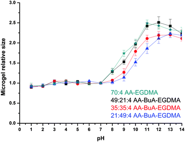
The pH responsiveness, in terms of swelling and shrinking, of the microgels was studied by measuring the size of the microgels at different pH values. As can be observed in Fig. 7, the size of the microgels increased with the increase in the pH of the solution, as was expected. The AA units at high pH become ionised due to deprotonation and thus more hydrophilic. This allows more water to enter the microgel, allowing it to swell. Furthermore, the anionic charges of the AA groups repel each other, forcing polymer chains to extend more and so cause the microgel to swell. This has been observed previously for (meth)acrylic acid containing microgels4,5,31,41 and macrogels.33–35,42–44 Note that the size of the microgels at very basic pH reduces because of increased ionic strength due to the increased NaOH concentration, as has also been observed in macrogels34,35 and microgels.31
When comparing the four different microgels it can be clearly observed that the size change, and thus the degree of swelling, was affected by the hydrophobic content but not at all pH values. At low pH, the AA units became protonated and non-ionised, while the hydrophobic content did not have an effect on the swelling ratio because the whole elastic chain (polymer chain between the crosslinks) was in a collapsed state. For example, at pH 7 the actual size/diameters of all microgels ranged from 17.9 to 18.6 μm. When exposed to high pHs the microgels with lesser hydrophobic content (i.e. lower BuA/AA ratio) swelled more since they were more anionic charges that forced the elastic chains to extend more as well as to repel each other, and thus force the whole microgel structure to swell. For example at pH 9 the diameter of the microgels increased from 21.3 to 31.0 μm as the AA content increased in the microgel. This was expected and similarly observed in macrogels.34,35,45–50
pKas of amphiphilic microgels
The hydrophobic content also influenced the pKa of the microgels, which were determined by potentiometric titration. Specifically, when the hydrophobic BuA content was varied between 0% (AA![[thin space (1/6-em)]](https://www.rsc.org/images/entities/char_2009.gif) :
:![[thin space (1/6-em)]](https://www.rsc.org/images/entities/char_2009.gif) BuA
BuA![[thin space (1/6-em)]](https://www.rsc.org/images/entities/char_2009.gif) :
:![[thin space (1/6-em)]](https://www.rsc.org/images/entities/char_2009.gif) EGDMA 70
EGDMA 70![[thin space (1/6-em)]](https://www.rsc.org/images/entities/char_2009.gif) :
:![[thin space (1/6-em)]](https://www.rsc.org/images/entities/char_2009.gif) 0
0![[thin space (1/6-em)]](https://www.rsc.org/images/entities/char_2009.gif) :
:![[thin space (1/6-em)]](https://www.rsc.org/images/entities/char_2009.gif) 4), 41% (21
4), 41% (21![[thin space (1/6-em)]](https://www.rsc.org/images/entities/char_2009.gif) :
:![[thin space (1/6-em)]](https://www.rsc.org/images/entities/char_2009.gif) 49
49![[thin space (1/6-em)]](https://www.rsc.org/images/entities/char_2009.gif) :
:![[thin space (1/6-em)]](https://www.rsc.org/images/entities/char_2009.gif) 4), 50% (35
4), 50% (35![[thin space (1/6-em)]](https://www.rsc.org/images/entities/char_2009.gif) :
:![[thin space (1/6-em)]](https://www.rsc.org/images/entities/char_2009.gif) 35
35![[thin space (1/6-em)]](https://www.rsc.org/images/entities/char_2009.gif) :
:![[thin space (1/6-em)]](https://www.rsc.org/images/entities/char_2009.gif) 4) and 59% (49
4) and 59% (49![[thin space (1/6-em)]](https://www.rsc.org/images/entities/char_2009.gif) :
:![[thin space (1/6-em)]](https://www.rsc.org/images/entities/char_2009.gif) 21
21![[thin space (1/6-em)]](https://www.rsc.org/images/entities/char_2009.gif) :
:![[thin space (1/6-em)]](https://www.rsc.org/images/entities/char_2009.gif) 4), based on the molar ratio of BuA (BuA/(BuA + AA) × 100%), the pKa values increased from 6.1 to 6.2, 6.4 and 6.6, respectively. Thus, the effective pKa values decreased as the AA content of the amphiphilic microgels increased, or equivalently, as the BuA content decreased. In other words, AA became a stronger acid as the microgels became less hydrophobic. This is because a decrease in the BuA content caused an increase in the hydrophilicity and in the dielectric constant of the microgels, rendering ionisation easier, which resulted in the lowering of the effective pKa.51 This has been similarly observed in anionic (meth)acrylic acid based amphiphilic macrogels34,35,45 and the reverse trend has been seen in amino (base) containing amphiphilic macrogels (pKa decreased with increasing hydrophobic content).46,49,50
4), based on the molar ratio of BuA (BuA/(BuA + AA) × 100%), the pKa values increased from 6.1 to 6.2, 6.4 and 6.6, respectively. Thus, the effective pKa values decreased as the AA content of the amphiphilic microgels increased, or equivalently, as the BuA content decreased. In other words, AA became a stronger acid as the microgels became less hydrophobic. This is because a decrease in the BuA content caused an increase in the hydrophilicity and in the dielectric constant of the microgels, rendering ionisation easier, which resulted in the lowering of the effective pKa.51 This has been similarly observed in anionic (meth)acrylic acid based amphiphilic macrogels34,35,45 and the reverse trend has been seen in amino (base) containing amphiphilic macrogels (pKa decreased with increasing hydrophobic content).46,49,50
Dye encapsulation and release studies
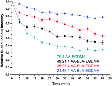
Having established that the microfluidically fabricated microgels were pH responsive, their ability to encapsulate and release both hydrophilic and hydrophobic moieties was examined. The intent was two-fold: (i) to prove the amphiphilic nature of the anionic AA microgels, and (ii) to determine their potential as delivery vehicles for drugs of varying hydrophobicity/hydrophilicity, similar to macrogels.52,53 A hydrophobic dye (Sudan I) and a hydrophilic dye (Trypan Blue) were employed as model drugs for these studies, with their release triggered by swelling of the microgels.The dye release rate was further investigated for each of the four types of microgel, and the results are shown in Fig. 9. Each of the microgels was able to encapsulate and release the dye, but there was a clear influence of the hydrophobic content on the release rate. In particular, by increasing the hydrophobic monomer (BuA) molar ratio content from 0% (70![[thin space (1/6-em)]](https://www.rsc.org/images/entities/char_2009.gif) :
:![[thin space (1/6-em)]](https://www.rsc.org/images/entities/char_2009.gif) 0
0![[thin space (1/6-em)]](https://www.rsc.org/images/entities/char_2009.gif) :
:![[thin space (1/6-em)]](https://www.rsc.org/images/entities/char_2009.gif) 4 AA
4 AA![[thin space (1/6-em)]](https://www.rsc.org/images/entities/char_2009.gif) :
:![[thin space (1/6-em)]](https://www.rsc.org/images/entities/char_2009.gif) Bu
Bu![[thin space (1/6-em)]](https://www.rsc.org/images/entities/char_2009.gif) :
:![[thin space (1/6-em)]](https://www.rsc.org/images/entities/char_2009.gif) EGDMA) to 70% (21
EGDMA) to 70% (21![[thin space (1/6-em)]](https://www.rsc.org/images/entities/char_2009.gif) :
:![[thin space (1/6-em)]](https://www.rsc.org/images/entities/char_2009.gif) 49
49![[thin space (1/6-em)]](https://www.rsc.org/images/entities/char_2009.gif) :
:![[thin space (1/6-em)]](https://www.rsc.org/images/entities/char_2009.gif) 4), the rate of release of the hydrophobic dye decreased. This was expected since the hydrophobic components of the microgel retained the hydrophobic dye in the microgel structure to a greater extent, as a result of hydrophobic interactions. Furthermore, the fact that the microgels with a higher hydrophobic content swelled less would also have an influence as it would slow the diffusion of the dye through the microgel, thus reducing the release rate.
4), the rate of release of the hydrophobic dye decreased. This was expected since the hydrophobic components of the microgel retained the hydrophobic dye in the microgel structure to a greater extent, as a result of hydrophobic interactions. Furthermore, the fact that the microgels with a higher hydrophobic content swelled less would also have an influence as it would slow the diffusion of the dye through the microgel, thus reducing the release rate.
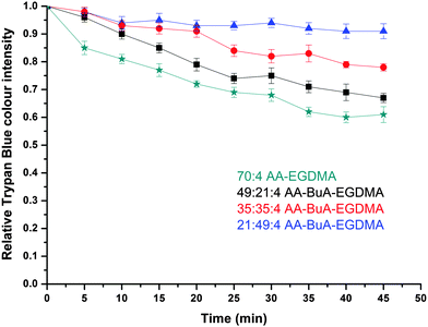
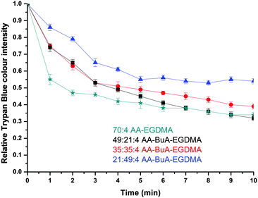
The release of the hydrophilic dye was further investigated over time for all four AA–BuA–EGDMA microgels in neutral (pH ∼7, Fig. 11) and basic (pH 11, Fig. 12) solutions. Two main observations can be made from the acquired data. Firstly, that by increasing the hydrophobic content (greater ratio of BuA), the hydrophilic dye release rate was decreased, as was expected and as had also been observed for the hydrophobic dye. This was as a result of the microgels with higher hydrophobic content swelling to a lesser extent, the pore/mesh size being smaller, and the fact that the dye could not diffuse out of the microgel as fast, compared to those with lower hydrophobic content. The second observation was that the dye release was much faster at pH 11 (Fig. 12) than pH 7 (Fig. 11). This was observed for all four varieties of microgels, and had similarly occurred in our previous studies,31 since more basic conditions yielded greater swelling (Fig. 7) due to the AA ionisation.
When comparing the hydrophobic Sudan I release to that of Trypan Blue from the amphiphilic microgels, the latter demonstrated much faster release characteristics for all four microgels at basic pH. For example, it took more than 40 min for the release of hydrophobic Sudan I from AA49-co-BuMA21-co-EGDMA4 microgels at basic pH to reach 50% of the relative colour intensity (compared to the initial intensity), while this level was reached in only 5 min during hydrophilic Trypan Blue release. This can be attributed to two factors: (i) the difficulty of the hydrophobic dye to diffuse into an aqueous environment compared to the hydrophilic dye, and (ii) the fact that the hydrophobic domains of the microgels would retain for longer the hydrophobic dye through hydrophobic interactions. It should be noted that this was observed in our previous study on off-chip polymerised AA–EGDMA microgels as well.31
In summary, the AA–BuA–EGDMA microgels were able to encapsulate and deliver both hydrophobic and hydrophilic dyes, and it has been demonstrated that the release rate can be tailored by adjusting the hydrophobic content of the amphiphilic microgels, which shows promise for their use in future drug delivery applications.
Conclusions
Amphiphilic microgels based on hydrophilic, ionisable acrylic acid (AA), hydrophobic, non-ionic n-butyl acrylate (BuA) and the hydrophobic crosslinker ethylene glycol dimethacrylate (EGDMA) were successfully fabricated in a lab-on-a-chip device via in situ generation and direct UV polymerisation of spherical precursor droplets in an expanded serpentine channel. The use of such an integrated microfluidic platform enabled the systematic variation of the amphiphilic nature of the microgels by varying the hydrophilic/hydrophobic monomer ratio, while maintaining the crosslinking density, producing microgels with narrower size distributions than those prepared by conventional methods. The microgels were pH responsive; by increasing the pH of the surrounding environment the microgels swelled due to ionisation of the AA units and the resultant electrostatic repulsion between the polymer chains inside the gel particles. Furthermore, it was demonstrated that the extent of swelling could be controlled by tailoring the hydrophobic content, as the microgel swelling was found to decrease by increasing the hydrophobic BuA content. Finally, the encapsulation and release of two model drugs, one hydrophobic dye and one hydrophilic dye, were investigated, and highlighted the amphiphilic nature of the microgels. The release was influenced by both the hydrophobic content of the microgels and the pH of the surrounding solution. In particular, by increasing the hydrophilic content of the microgels and suspending them in a more basic solution, the release of the dyes was accelerated. These properties and initial trials show great potential for the use of on-chip generated amphiphilic microgels for the encapsulation and triggered release of hydrophilic and hydrophobic payloads, particularly with a view to drug delivery applications.Acknowledgements
University of Hull is thanked for funding Mr Lu's PhD studentship. Dr Stephen Clark is thanked for fabrication of the microfluidic devices.Notes and references
- V. Alakhov, G. Pietrzynski, K. Patel, A. Kabanov, L. Bromberg and T. A. Hatton, J. Pharm. Pharmacol., 2004, 56, 1233–1241 CrossRef CAS PubMed.
- Y. Jiang, J. Chen, C. Deng, E. J. Suuronen and Z. Zhong, Biomaterials, 2014, 35, 4969–4985 CrossRef CAS PubMed.
- Y. Gao, A. Ahiabu and M. J. Serpe, ACS Appl. Mater. Interfaces, 2014, 6, 13749–13756 CAS.
- L. Bromberg, M. Temchenko and T. A. Hatton, Langmuir, 2002, 18, 4944–4952 CrossRef CAS.
- J. P. K. Tan and K. C. Tam, J. Controlled Release, 2007, 118, 87–94 CrossRef CAS PubMed.
- W. C. Lee, Y. C. Li and I. M. Chu, Macromol. Biosci., 2006, 6, 846–854 CrossRef CAS PubMed.
- L. Li, C. Cheng, M. P. Schürings, X. Zhu and A. Pich, Polymer, 2012, 53, 3117–3123 CrossRef CAS.
- M. Dadsetan, K. E. Taylor, C. Yong, Ž. Bajzer, L. Lu and M. J. Yaszemski, Acta Biomater., 2013, 9, 5438–5446 CrossRef CAS PubMed.
- H. Bysell, R. Månsson, P. Hansson and M. Malmsten, Adv. Drug Delivery Rev., 2011, 63, 1172–1185 CrossRef CAS PubMed.
- T. Trongsatitkul and B. M. Budhlall, Polym. Chem., 2013, 4, 1502–1516 RSC.
- M. R. Islam, A. Ahiabu, X. Li and M. J. Serpe, Sensors, 2014, 14, 8984–8995 CrossRef CAS PubMed.
- Y. Chen, Y. Bai, S. Chen, J. Jup, Y. Li, T. Wang and Q. Wang, ACS Appl. Mater. Interfaces, 2014, 6, 13334–13338 CAS.
- D. Parasuraman and M. J. Serpe, ACS Appl. Mater. Interfaces, 2011, 3, 4714–4721 CAS.
- D. Parasuraman and M. J. Serpe, ACS Appl. Mater. Interfaces, 2011, 3, 2732–2737 CAS.
- C. D. Sorrell, M. C. D. Carter and M. J. Serpe, ACS Appl. Mater. Interfaces, 2011, 3, 1140–1147 CAS.
- H. M. Shewan and J. R. Stokes, J. Food Eng., 2013, 119, 781–792 CrossRef CAS.
- R. Yin, X. Cha, X. Zhang and J. Shen, Macromolecules, 1990, 23, 5158–5160 CrossRef CAS.
- L. Bromberg, M. Temchenko, G. D. Moeser and T. A. Hatton, Langmuir, 2004, 20, 5683–5692 CrossRef CAS PubMed.
- X. Wang, X. Hou, Y. Wu and S. You, J. Appl. Polym. Sci., 2009, 114, 4042–4050 CrossRef CAS.
- H. Li, X. Cui, S. Shen and D. Hu, J. Appl. Polym. Sci., 2011, 122, 509–516 CrossRef CAS.
- H. Li, P. Zhang, L. Zhang, T. Zhou and D. Hu, J. Mater. Chem., 2009, 19, 4575–4586 RSC.
- T. Zhou, H. Li, G. Liu, L. Zhang, D. Yao and D. Hu, J. Appl. Polym. Sci., 2009, 114, 4000–4010 CrossRef CAS.
- M. D. Tarn and N. Pamme, in Elsevier Reference Module in Chemistry, Molecular Sciences and Chemical Engineering, ed. J. Reedijk, Elsevier, Waltham, MA, 2013 Search PubMed.
- H. Song, D. L. Chen and R. F. Ismagilov, Angew. Chem., Int. Ed., 2006, 45, 7336–7356 CrossRef CAS PubMed.
- S.-Y. Teh, R. Lin, L.-H. Hung and A. P. Lee, Lab Chip, 2008, 8, 198–220 RSC.
- E. Tumarkin and E. Kumacheva, Chem. Soc. Rev., 2009, 38, 2161–2168 RSC.
- S. Seiffert and D. A. Weitz, Polymer, 2010, 51, 5883–5889 CrossRef CAS.
- W. J. Duncanson, T. Lin, A. R. Abate, S. Seiffert, R. K. Shah and D. A. Weitz, Lab Chip, 2012, 12, 2135–2145 RSC.
- S. Seiffert, Angew. Chem., Int. Ed., 2013, 52, 11462–11468 CrossRef CAS PubMed.
- P. Van De Watering, N. J. Zuidam, M. J. Van Steenbergen, O. A. G. J. Van Der Houwen, W. J. M. Underberg and W. E. Hennink, Macromolecules, 1998, 31, 8063–8068 CrossRef.
- B. Lu, M. D. Tarn, N. Pamme and T. K. Georgiou, J. Mater. Chem. B, 2015, 3, 4524–4529 RSC.
- S. N. Georgiades, M. Vamvakaki and C. S. Patrickios, Macromolecules, 2002, 35, 4903–4911 CrossRef CAS.
- T. K. Georgiou, L. A. Phylactou and C. S. Patrickios, Biomacromolecules, 2006, 7, 3505–3512 CrossRef CAS PubMed.
- G. Kali, T. K. Georgiou, B. Iván, C. S. Patrickios, E. Loizou, Y. Thomann and J. C. Tiller, Langmuir, 2007, 23, 10746–10755 CrossRef CAS PubMed.
- G. Kali, T. K. Georgiou, B. Iván, C. S. Patrickios, E. Loizou, Y. Thomann and J. C. Tiller, Macromolecules, 2007, 40, 2192–2200 CrossRef CAS.
- K. S. Pafiti, Z. Philippou, E. Loizou, L. Porcar and C. S. Patrickios, Macromolecules, 2011, 44, 5352–5362 CrossRef CAS.
- T. McCreedy, Anal. Chim. Acta, 2001, 427, 39–43 CrossRef CAS.
- A. Pal and S. Chaudhary, Fluid Phase Equilib., 2014, 372, 100–104 CrossRef CAS.
- D. Di Carlo, D. Irimia, R. G. Tompkins and M. Toner, Proc. Natl. Acad. Sci. U. S. A., 2007, 104, 18892–18897 CrossRef CAS PubMed.
- D. Di Carlo, Lab Chip, 2009, 9, 3038–3046 RSC.
- G. M. Eichenbaum, P. F. Kiser, A. V. Dobrynin, S. A. Simon and D. Needham, Macromolecules, 1999, 32, 4867–4878 CrossRef CAS.
- G. Kali and B. Iván, Macromol. Chem. Phys., 2015, 216, 605–613 CrossRef CAS.
- M. Haraszti, E. Tóth and B. Iván, Chem. Mater., 2006, 18, 4952–4958 CrossRef CAS.
- B. Iván, M. Haraszti, G. Erdödi, J. Scherble, R. Thomann and R. Mülhaupt, Macromol. Symp., 2005, 227, 265–273 CrossRef.
- G. Kali, T. K. Georgiou, B. Iván and C. S. Patrickios, J. Polym. Sci., Part A: Polym. Chem., 2009, 47, 4289–4301 CrossRef CAS.
- T. K. Georgiou, C. S. Patrickios, P. W. Groh and B. Iván, Macromolecules, 2007, 40, 2335–2343 CrossRef CAS.
- D. S. Achilleos, T. K. Georgiou and C. S. Patrickios, Biomacromolecules, 2006, 7, 3396–3405 CrossRef CAS PubMed.
- A. I. Triftaridou, E. Loizou and C. S. Patrickios, J. Polym. Sci., Part A: Polym. Chem., 2008, 46, 4420–4432 CrossRef CAS.
- A. I. Triftaridou, S. C. Hadjiyannakou, M. Vamvakaki and C. S. Patrickios, Macromolecules, 2002, 35, 2506–2513 CrossRef CAS.
- M. Vamvakaki and C. S. Patrickios, Soft Matter, 2008, 4, 268 RSC.
- O. E. Philippova, D. Hourdet, R. Audebert and A. R. Khokhlov, Macromolecules, 1997, 30, 8278–8285 CrossRef CAS.
- P. Papaphilippou, M. Christodoulou, O. M. Marinica, A. Taculescu, L. Vekas, K. Chrissafis and T. Krasia-Christoforou, ACS Appl. Mater. Interfaces, 2012, 4, 2139–2147 CAS.
- N. Ghasdian, E. Church, A. P. Cottam, K. Hornsby, M. Y. Leung and T. K. Georgiou, RSC Adv., 2013, 3, 19070–19080 RSC.
| This journal is © The Royal Society of Chemistry 2016 |

