 Open Access Article
Asymmetric supercapacitors with high energy density based on helical hierarchical porous NaxMnO2 and MoO2†
Xue-Feng
Lu
,
Zhi-Xiang
Huang
,
Ye-Xiang
Tong
and
Gao-Ren
Li
*
MOE Laboratory of Bioinorganic and Synthetic Chemistry, KLGHEI of Environment and Energy Chemistry, School of Chemistry and Chemical Engineering, Sun Yat-sen University, Guangzhou 510275, China. E-mail: ligaoren@mail.sysu.edu.cn
First published on 7th October 2015
Abstract
Helical hierarchical porous NaxMnO2/CC and MoO2/CC, which are assembled from nanosheets and nanoparticles, respectively, are fabricated using a simple electrodeposition method. These unique helical porous structures enable electrodes to have a high capacitance and an outstanding cycling performance. Based on the helical NaxMnO2/CC as the positive electrodes and helical MoO2/CC as the negative electrodes, high performance NaxMnO2/CC//MoO2/CC asymmetric supercapacitors (ASCs) are successfully assembled, and they achieve a maximum volume Csp of 2.04 F cm−3 and a maximum energy density of 0.92 mW h cm−3 for the whole device and an excellent cycling stability with 97.22% Csp retention after 6000 cycles.
1. Introduction
Increasing demands in portable electronics and future green transportation are pushing the research towards electrochemical energy storage (EES) systems with high energy density, high power density and long cycling life.1 Electrochemical capacitors, also known as supercapacitors, bridge the gap between batteries and conventional capacitors in terms of their high power density and have been regarded as the most promising EES devices.2 However, their energy density is still relatively low, which has restricted their potential applications. Therefore, the improvement of energy density is crucial for supercapacitors to meet future energy demands.As we know, the energy density of a supercapacitor device can be calculated according to the equation E = 1/2CspV2, and it can be enhanced by maximizing the specific capacitance (Csp) and operation voltage (V).3 The promising approach for the enhancement of Csp is to develop new electrodes with high Csp values.4 An effective approach to increase the operation voltage is to use an organic electrolyte, which can provide a wide voltage window up to 3.0 V. However, they suffer from high cost, poor ionic conductivity and high toxicity, which limit their wide application. In addition, a promising alternative for increasing the operation voltage is to develop asymmetric supercapacitors (ASCs), which typically consist of cathodes as the energy source and anodes as the power source.5 Compared with symmetric supercapacitors, the ASCs take advantage of the different voltage windows of two electrodes in the same electrolyte to increase the device operating voltage and thus significantly improve the energy density. In recent decades, intensive efforts have been devoted to explore various ASCs, such as H–TiO2@MnO2//H–TiO2@C (1.8 V),4 ZnO@MnO2//rGO (1.8 V),6 Ni/NiO//rGO (1.5 V),7 and NiCo2O4//active carbon (1.5 V).8 Most ASCs use carbon-based materials as negative electrodes because of their large surface area, excellent electrical conductivity and outstanding stability.9 However, the low Csp of carbon materials severely limits the energy density of the SCs according to the equation of 1/C = 1/Can + 1/Ccat (Can: capacitance of the anode; Ccat: capacitance of the cathode). In this regard, some new negative electrodes with high Csp values, such as MoO3,3a,10 Fe2O3,11 and some metal nitrides12 have been developed for ASCs. But due to the narrow voltage window, the unbalanced capacity between the cathode and anode electrodes and the unsatisfactory cycling stability of metal oxide negative electrodes, it is still a huge challenge to achieve ASCs with high energy and power densities.
Based on the above considerations, in this paper we designed and synthesized helical hierarchical porous NaxMnO2 and MoO2 on carbon cloth (CC) as the positive and negative electrodes, respectively, for ASCs. Manganese oxides have been widely thought to be the most promising material because of their low cost, high abundance, large theoretical Csp, and environmental friendliness.13 As a polymorph of MnO2, the sodium–birnessite-type MnO2 (NaxMnO2) has a two-dimensional layer-structure with bicontinuous networks of solids and pores,14 and it is an attractive candidate for ASCs as a positive electrode material. MoO2 as a negative electrode was investigated because of its rich chemistry associated with multiple valence states, low electrical resistivity, natural abundance, and affordable cost.15 The unique helical hierarchical porous structure of NaxMnO2 was assembled from nanosheets and that of MoO2 was assembled from mesoporous nanoparticles. The helix is a fantastic yet ubiquitous geometry in nature, science, art and architecture, and it exhibits distinctive mechanical, chemical, and physical properties.16 When a helical structure is used in electrodes for supercapacitors, the appropriate spiral distance and diameter are in favor of electrolyte insertion and thus will improve the utilization ratio of the active material. The interspace between two pitches can serve as an “ion reservoir” and further improve the cycling stability of the electrodes. The hierarchical porous structure will be much less vulnerable to dissolution, Ostwald ripening and aggregation, and will provide a large surface area and fast electrolyte penetration/diffusion. Besides, the hierarchical porous structure can also buffer the volume change well, avoiding the structural collapse of the electrodes during the charge/discharge process. The electrochemical measurements demonstrate that the helical hierarchical porous NaxMnO2 shows a maximal areal capacitance of 329.69 mF cm−2 with a potential window of 0–1.0 V and the helical hierarchical porous MoO2 shows a maximal areal Csp of 174.97 mF cm−2 with a potential window of −1.1–0 V. The ASC device was assembled based on the helical hierarchical porous NaxMnO2/CC as the positive electrode and helical hierarchical porous MoO2/CC as the negative electrode, and it shows a high volume Csp of 2.04 F cm−3 and a high energy density of 0.92 mW h cm−3 based on the whole device. Meanwhile, such an ASC device exhibits a high cycling life with 97.22% Csp retention after 6000 cycles. The present encouraging findings will open up a new opportunity for the development of ASCs with high energy and power densities.
2. Experimental section
Preparation of electrode materials
All the chemical reagents used in this study were of analytical grade (AR). Electrodeposition was carried out in a simple two-electrode cell via galvanostatic electrolysis and a graphite electrode was used as a counter electrode (spectral grade). Carbon cloth was used as the working electrode for the electrodeposition and it was washed with ethanol and water successively in an ultrasonic bath for 5 min. The helical NaxMnO2 was electrodeposited on the carbon cloth in a 15 mL solution of 0.02 M Mn(CH3COO)2 + 0.2 M Na2SO4 at a current density of 4.0 mA cm−2 on the anode at room temperature for 10 min. The electrodeposition process is expressed as follows:14,19| Mn2+ + 2H2O + xNa+ → NaxMnx3+Mn(1−x)4+O2 + 4H+ + (2−x)e− | (1) |
The helical MoO2 was electrodeposited in a 15 mL solution of 0.01 M (NH4)6Mo7O24 at a current density of 4.0 mA cm−2 on the cathode at room temperature for 30 min followed by an annealing process in an NH3 atmosphere. The electrodeposition process is expressed as follows:
| 6NH4+ + Mo7O246− + (18 − 7x)H2O + (42 − 14x)e− → 7MoOx + 6NH3 + (42 − 14x)OH− | (2) |
Fabrication of ASCs
The ASC device was assembled using the helical NaxMnO2/CC as the positive electrode and helical MoO2/CC as the negative electrode with a separator (NKK separator; Nippon Kodoshi Corporation, Kochi, Japan) between the two electrodes. A Na2SO4 aqueous solution (1.0 M) was used as the electrolyte. To avoid leakage of the electrolyte, the entire device was sealed by two pieces of PET membrane with a small part of the electrode kept outside.Material characterizations and electrochemical measurements
The morphologies, microstructures and compositions of the products were characterized using field-emission scanning electron microscopy (FE-SEM, JSM-6330F), X-ray diffraction (XRD, D-MAX 2200 VPC), transmission electron microscopy (TEM, Tecnai™ G2 F30), and X-ray photoelectron spectroscopy (XPS, ESCALab250). Inductively coupled plasma atomic emission spectroscopy (ICP, SPECTRO) was used to analyze the loading of the active materials. The electrochemical measurements of the electrodes were carried out in a standard three-electrode electrolytic cell in 1.0 M Na2SO4 aqueous solution. A graphite electrode was used as the counter electrode. A saturated calomel electrode (SCE) was used as the reference electrode. The cyclic voltammetry and chronopotentiometric measurements were performed using a CHI 760E electrochemical workstation (CH instruments, Inc.) to determine the electrochemical properties. EIS was conducted in the frequency range between 0.01 Hz and 100 kHz with an amplitude of 5 mV at the open-circuit potential.3. Results and discussion
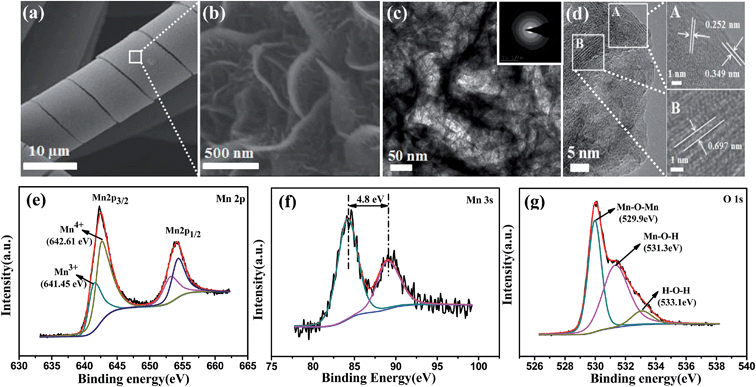
As shown in Scheme 1, the electrodeposition method was used to fabricate the helical hierarchical porous NaxMnO2 and MoO2, which were directly grown on carbon cloth without a binder (the details are described in the Experimental section). SEM images of NaxMnO2 with different magnifications are shown in Fig. 1a and S1a,† which show the perfect and uniform helical structures grown on carbon fibers. More interestingly, the magnified SEM image in Fig. 1b shows that the helical structures consist of nanosheets. The thickness of these nanosheets is 15–20 nm. TEM images of NaxMnO2 are shown in Fig. 1c and S1b,† which clearly show the porous structures. The HRTEM image in Fig. 1d shows the lattice spacings of 0.697, 0.349 and 0.252 nm, which correspond to (001), (002) and (100) crystal planes of NaxMnO2, respectively.17 The SAED pattern in the inset of Fig. 1c also shows the polycrystalline structure of NaxMnO2. A cross-sectional SEM image in Fig. S2† shows that the thickness of the helical microstructures is ∼1.0 μm. The surface electronic state and chemical composition of the helical NaxMnO2 was examined using an XPS spectrum. The XPS survey spectrum of the helical NaxMnO2 is shown in Fig. S3,† which shows the existence of the elements Mn, O, Na and C. The signals of C come from the carbon cloth substrate. The atomic ratio of Na/Mn is about 0.2, which is confirmed using energy dispersive X-ray spectroscopy (EDX) as shown in Fig. S4.† In the Mn 2p spectra (Fig. 1e), two kinds of manganese species containing Mn3+ and Mn4+ can be observed. The fitting peaks at 641.45 eV and 653.15 eV are indexed to Mn3+, while the fitting peaks at 642.61 eV and 654.31 eV are indexed to Mn4+.18 Additionally, the Mn 3s peaks are useful for determining the oxidation state of Mn. In Fig. 1f, the energy separation between the two peaks of Mn 3s is 4.8 eV, which corresponds to an average Mn oxidation state of ∼3.8 according to a linear relationship between the oxidation state of manganese and the ΔE value.18,19 The atomic ratio of Mn3+/Mn4+ in the sample is about 1/4. The O 1s spectrum shown in Fig. 1g is deconvoluted into three components. The bands at 529.9, 531.3 and 533.1 eV can be assigned to the oxygen bonds of Mn–O–Mn, Mn–O–H and H–O–H, respectively.19 The bond of Mn–O–Mn comes from NaxMnO2 and those of Mn–O–H and H–O–H can be attributed to the adsorbed H2O or crystal H2O. Based on the above results, the composition of the sodium–birnessite-type manganese oxide can be identified as Na0.2MnO2 (Na0.2Mn0.23+Mn0.84+O2).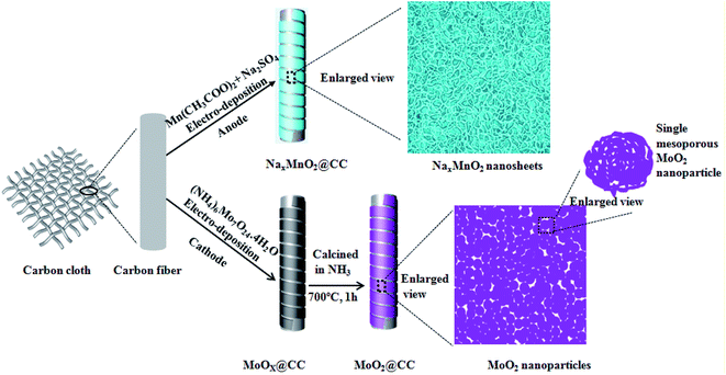 | ||
| Scheme 1 Representation of the fabrication of the helical hierarchical porous NaxMnO2/CC and MoO2/CC. | ||
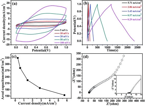
Cyclic voltammetry (CV) and galvanostatic charge–discharge (GCD) are generally used to characterize the capacitance behavior of an electrode material. Fig. 2a and b show the typical CV and GCD curves of the helical NaxMnO2/CC at different scan rates and current densities, respectively, in 1.0 M Na2SO4 solution. In the potential range of 0–1.0 V, the behavior of the helical NaxMnO2/CC slightly deviates from the ideal rectangular shape with a small and broad redox couple, indicating the pseudocapacitance properties of the NaxMnO2/CC. These redox peaks can be definitely ascribed to the intercalation–deintercalation of Na+ into and from the solid MnO2 lattice.14,19,20 The GCD curves of the helical NaxMnO2/CC are almost linear and symmetrical without an obvious IR drop as shown in Fig. 2b, indicating a rapid I–V response and a good capacitance performance. The areal Csp of the helical NaxMnO2/CC obtained from the GCD curves is shown in Fig. 2c, which shows that the highest Csp is 329.69 mF cm−2 at a current density of 0.29 mA cm−2. The Csp value of 329.69 mF cm−2 is much higher than those of the other MnO2 electrodes reported in the literature (10–100 mF cm−2).4,21 In addition, the helical NaxMnO2/CC electrode has a small charge-transfer resistance (Rct) of ∼1.5 Ω as shown in Fig. 2d, suggesting fast charge transfer and transport processes.22 Fig. S7† shows the excellent cycling stability of the helical NaxMnO2/CC and a high Csp retention of 99.97% after 5000 cycles is achieved. In addition, Fig. S8† shows the EIS spectra of the helical NaxMnO2/CC before and after 5000 cycles, from which we can see that the charge-transfer resistance is almost unchanged after 5000 cycles.
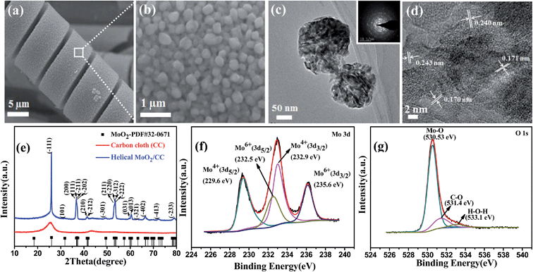
The helical MoO2/CC as a negative electrode was fabricated as shown in Fig. 3a. The helical structure is constructed by nanoparticles with diameters of 100–200 nm as shown in Fig. 3b and S9a.† A TEM image of MoO2 is shown in Fig. S9b,† which clearly shows the porous structures. The thickness of the helical structure is ∼3.5 μm as shown in Fig. S9a.† More importantly, the magnified TEM shows these nanoparticles are mesoporous as shown in Fig. 3c, which will be beneficial to enhance the specific surface area and thus will provide more active reaction sites. Fig. 3d shows the HRTEM image of the helical MoO2, in which the lattice spacings of 0.243, 0.240, 0.171 and 0.170 nm correspond to (−211), (−202), (−312) and (−222) crystal planes of MoO2 (JCPDS#32-0671), respectively.23 The SAED pattern in the inset of Fig. 3c reveals the diffraction rings of the typical monoclinic structure of MoO2, which is in accordance with the results from the XRD pattern shown in Fig. 3e. All diffraction peaks can be assigned to the monoclinic MoO2 phase and no diffraction peak comes from other molybdenum oxides such as MoO3. The survey XPS spectra of the MoO2 electrode is shown in Fig. S10,† which indicates the presence of Mo, O and C elements in the sample. The atomic ratio of Mo/O is about 2, which is consistent with stoichiometric MoO2 composition. The elemental C comes from the carbon cloth that is used as the substrate. The high-resolution XPS spectrum of Mo 3d can be deconvoluted into two doublets as shown in Fig. 3f. The binding energies of the Mo 3d5/2 and 3d3/2 peaks at 229.6 and 232.9 eV indicate the oxidation state of Mo(IV).24 In addition, the small peaks at 232.5 and 235.6 eV are seen, and they correspond to Mo(VI) 3d5/2 and 3d3/2, respectively, indicating the existence of Mo(VI). This can be attributed to the partial surface oxidation of MoO2 in air.24,25 The XPS spectrum of O 1s is shown in Fig. 3g, which shows that the main peak at 530.53 eV can be assigned to the Mo–O bond. The bands of 531.4 and 533.1 eV correspond to C–O and O–H bonds, respectively,24,25 and they can be attributed to the adsorbed H2O on the carbon cloth.
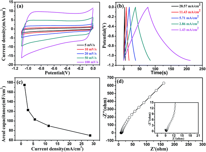
The fabricated helical MoO2/CC electrode possesses a perfect capacitance behavior with a wide potential window of −1.1–0 V (vs. SCE) in a solution of 1.0 M Na2SO4. The wide potential window may be the result of the high overpotential of H2 and O2 evolution, which is related to the structure and properties of the electrode material.26Fig. 4a and b show the CV and GCD curves of the helical MoO2/CC, respectively, which are symmetric and linear, respectively, without an obvious IR drop, indicating a good capacitance performance. As shown in Fig. 4c, the highest areal Csp obtained from the GCD curves is 174.97 mF cm−2 at a current density of 1.43 mA cm−2, which is much larger than those of other metal oxide/nitride negative electrodes, such as α-Fe2O3,27 MoO3,28a and VN.12a,28b The kinetic features of the helical MoO2/CC electrode were further investigated by measuring the EIS spectrum as shown in Fig. 4d, which shows a small bulk solution resistance (Rs) of 7.5 Ω,29 a small charge-transfer resistance (Rct) of 0.5 Ω, and fast ion diffusion into the MoO2/CC electrode.30 Moreover, the helical MoO2/CC shows a high cycling stability with a Csp retention of 91.62% after 5000 cycles as shown in Fig. S12.† To evaluate the change of charge-transfer resistance, we compared the EIS spectra of the helical MoO2/CC before and after the cycling test as shown in Fig. S13,† from which we can see that the charge-transfer resistance of the electrode becomes a little bigger after 5000 cycles.
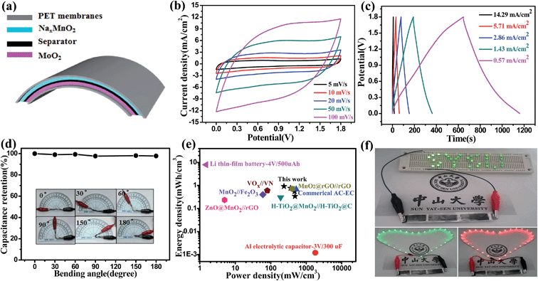
The flexible asymmetric supercapacitor (ASC) device was assembled using the helical NaxMnO2/CC as the positive electrode and the helical MoO2/CC as the negative electrode (NaxMnO2/CC//MoO2/CC ASC). Fig. 5a shows the schematic structure of the NaxMnO2/CC//MoO2/CC ASC, which is sealed by two thin pieces of PET membrane. Taking advantage of the different potential windows of the NaxMnO2/CC and MoO2/CC electrodes (Fig. S14a†), the operating cell potential of the assembled ASCs is expected to be 2.1 V. However, a faradic reaction is observed in the CV and GCD curves beyond the potential of 1.8 V. As shown in Fig. S14b,† an oxidation peak is observed beyond 1.8 V, highlighted by a dashed box, which is also observed in the GCD curves (Fig. S14c†). When the ASC devices were tested in the potential windows of 2.0 and 2.1 V for 6000 cycles, their capacitance retention is only 63.01% and 40.25%, respectively, as shown in Fig. S14d.† However, when tested in a potential window of 1.8 V, the ASC has a good cycling stability with a much higher capacitance retention of 97.22%, which is significantly better than those reported in previous work (typically 70–85% retention over 1000 cycles).26a,32
Fig. 5b shows the CV curves of an optimized NaxMnO2/CC//MoO2/CC ASC at different scan rates with a potential window of 0–1.8 V in 1.0 M Na2SO4 electrolyte. These CV curves exhibit rectangular-like shapes, revealing an ideal capacitive behavior and fast charge/discharge properties. As shown in Fig. 5c, the GCD curves at different current densities are all reasonably symmetrical and show a good linear relationship of the charge/discharge voltage versus time particularly at a low current density. This result also indicates the ideal capacitive characteristics and the rapid charge/discharge properties of the assembled ASC device. The volumetric Csp calculated using the discharging curves is shown in Fig. S15,† which shows the highest Csp of 2.04 F cm−3 at 0.57 mA cm−2. The Csp of 2.04 F cm−3 is much larger than those of the ASCs reported recently.4,11a,12a,31 In order to demonstrate the flexibility, we measured the CV curves of the assembled ASCs with different bending angles from 0° to 180° at a scan rate of 100 mV s−1. As shown in Fig. 5d and S16,† there is no significant Csp loss under the different bending angles, suggesting excellent flexibility properties.
The flexible NaxMnO2/CC//MoO2/CC ASC exhibits the highest energy density of 0.92 mW h cm−3 at a power density of 236.15 mW cm−3 as shown in Fig. 5e. It preserves 36.96% of the highest energy density when the power density increases to the maximal value (483.19 mW cm−3). Here the energy densities are superior to those of the previously reported similar ASC systems, including MnO2//Fe2O3 (1.6 V, 0.40 mW h cm−3),11a H–TiO2@MnO2//H–TiO2@C (1.8 V, 0.30 mW h cm−3),4 ZnO@MnO2//rGO (1.8 V, 0.234 mW h cm−3),6 and even VOx//VN (1.8 V, 0.61 mW h cm−3).12a To show the practical application, three ASC devices were assembled in series. As shown in Fig. 5f, the ASCs can light a SYSU logo consisting of 32 green LEDs and a 50 cm long commercial red (2.0 V) and green (2.5 V) LED soft rope light, indicating high power and energy densities of the NaxMnO2/CC//MoO2/CC ASCs.
4. Conclusions
In summary, we pioneered an electrochemical method for the synthesis of helical NaxMnO2/CC and MoO2/CC with hierarchical porous structures, which are assembled from nanosheets and mesoporous nanoparticles, respectively. These unique electrode structures enable a high working voltage in aqueous solutions, a high areal capacitance and an outstanding cycling performance. High-performance NaxMnO2/CC//MoO2/CC ASCs based on the helical NaxMnO2/CC as the positive electrodes and the helical MoO2/CC as the negative electrodes are assembled, and they achieve a maximum volume Csp of 2.04 F cm−3 and a maximum energy density of 0.92 mW h cm−3 based on the whole device. Furthermore, the NaxMnO2/CC//MoO2/CC ASCs exhibit an excellent cycling stability with 97.22% capacitance retention after 6000 cycles. These findings will open new opportunities for the development of helical hierarchical porous metal oxide electrodes for ASC devices with high energy and power densities.Acknowledgements
This work was supported by National Natural Science Foundation of China (51173212 and J1103305), National Basic Research Program of China (2015CB932304), Natural Science Foundation of Guangdong Province (S2013020012833), Fundamental Research Fund for the Central Universities (13lgpy51), SRF for ROCS, SEM ([2012]17071707), Project of High Level Talents in Higher School of Guangdong Province, Science and Technology Planning Project of Guangdong Province (2013B010403011) and Open-End Fund of Key Laboratory of Functional Inorganic Material Chemistry (Heilongjiang University), Ministry of Education.References
- (a) C. Liu, F. Li, L. P. Ma and H. M. Cheng, Adv. Mater., 2010, 22, 28 CrossRef PubMed; (b) G. Yu, L. Hu, M. Vosgueritchian, H. Wang, X. Xie, J. R. McDonough, X. Cui, Y. Cui and Z. Bao, Nano Lett., 2011, 11, 2905 CrossRef CAS PubMed; (c) H. Xia, C. Hong, B. Li, B. Zhao, Z. Lin, M. Zheng, S. V. Savilov and S. M. Aldoshin, Adv. Funct. Mater., 2015, 25, 627 CrossRef CAS PubMed.
- (a) P. Simon and Y. Gogotsi, Nat. Mater., 2008, 7, 845 CrossRef CAS PubMed; (b) J. R. Miller and P. Simon, Science, 2008, 321, 651 CrossRef CAS PubMed; (c) R. Liu, F. Wong, W. Duan and A. Sen, Adv. Mater., 2013, 25, 6997 CrossRef CAS PubMed; (d) C. Zhu, P. Yang, D. Chao, X. Wang, X. Zhang, S. Chen, B. K. Tay, H. Huang, H. Zhang, W. Mai and H. J. Fan, Adv. Mater., 2015, 27, 4566 CrossRef CAS PubMed; (e) G. D. Moon, J. B. Joo, M. Dahl, H. Jung and Y. Yin, Adv. Funct. Mater., 2014, 24, 848 CrossRef CAS PubMed.
- (a) J. Chang, M. Jin, F. Yao, T. H. Kim, V. T. Le, H. Yue, F. Gunes, B. Li, A. Ghosh, S. Xie and Y. H. Lee, Adv. Funct. Mater., 2013, 23, 5074 CrossRef CAS PubMed; (b) P. J. Hall, M. Mirzaeian, S. I. Fletcher, F. B. Sillars, A. J. R. Rennie, G. O. Shitta-Bey, G. Wilson, A. Cruden and R. Carter, Energy Environ. Sci., 2010, 3, 1238 RSC; (c) J. Feng, X. Sun, C. Wu, L. Peng, C. Lin, S. Hu, J. Yang and Y. Xie, J. Am. Chem. Soc., 2011, 133, 17832 CrossRef CAS PubMed.
- (a) X. Lu, M. Yu, G. Wang, T. Zhai, S. Xie, Y. Ling, Y. Tong and Y. Li, Adv. Mater., 2013, 25, 267 CrossRef CAS PubMed; (b) C. Wu, X. Lu, L. Peng, K. Xu, X. Peng, J. Huang, G. Yu and Y. Xie, Nat. Commun., 2013, 4, 2431 Search PubMed; (c) H. Xia, C. Hong, X. Shi, B. Li, G. Yuan, Q. Yao and J. Xie, J. Mater. Chem. A, 2015, 3, 1216 RSC; (d) D. Chao, X. Xia, C. Zhu, J. Wang, J. Liu, J. Lin, Z. Shen and H. J. Fan, Nanocale, 2014, 6, 5691–5697 CAS.
- (a) X. Lu, M. Yu, G. Wang, Y. Tong and Y. Li, Energy Environ. Sci., 2014, 7, 2160 RSC; (b) J.-X. Feng, S.-H. Ye, A.-L. Wang, X.-F. Lu, Y.-X. Tong and G.-R. Li, Adv. Funct. Mater., 2014, 24, 7093 CrossRef CAS PubMed; (c) C. Zhou, Y. Zhang, Y. Li and J. Liu, Nano Lett., 2013, 13, 2078 CrossRef CAS PubMed.
- W. Zilong, Z. Zhu, J. Qiu and S. Yang, J. Mater. Chem. C, 2014, 2, 1331 RSC.
- M. Yu, W. Wang, C. Li, T. Zhai, X. Lu and Y. Tong, NPG Asia Mater., 2014, 6, 129 CrossRef PubMed.
- X. F. Lu, D. J. Wu, R. Z. Li, Q. Li, S. H. Ye, Y. X. Tong and G. R. Li, J. Mater. Chem. A, 2014, 2, 4706 CAS.
- (a) L. Liu, Z. Niu, L. Zhang, W. Zhou, X. Chen and S. Xie, Adv. Mater., 2014, 26, 4855–4862 CrossRef CAS PubMed; (b) L. Dai, D. W. Chang, J. B. Baek and W. Lu, Small, 2012, 8, 1130 CrossRef CAS PubMed.
- G. R. Li, Z. L. Wang, F. L. Zheng, Y. N. Ou and Y. X. Tong, J. Mater. Chem., 2011, 21, 4217 RSC.
- (a) X. Lu, Y. Zeng, M. Yu, T. Zhai, C. Liang, S. Xie, M. S. Balogun and Y. Tong, Adv. Mater., 2014, 26, 3148 CrossRef CAS PubMed; (b) P. Yang, Y. Ding, Z. Lin, Z. Chen, Y. Li, P. Qiang, M. Ebrahimi, W. Mai, C. P. Wong and Z. L. Wang, Nano Lett., 2014, 14, 731 CrossRef CAS PubMed.
- (a) X. Lu, M. Yu, T. Zhai, G. Wang, S. Xie, T. Liu, C. Liang, Y. Tong and Y. Li, Nano Lett., 2013, 13, 2628 CrossRef CAS PubMed; (b) K.-H. Lee, Y.-W. Lee, A. R. Ko, G. Cao, K.-W. Park and B. Vyas, J. Am. Ceram. Soc., 2013, 96, 37 CrossRef CAS PubMed.
- (a) Q. Li, Z.-L. Wang, G.-R. Li, L.-X. Ding and Y.-X. Tong, Nano Lett., 2012, 12, 3803 CrossRef CAS PubMed; (b) Z.-P. Feng, G.-R. Li, J.-H. Zhong, Z.-L. Wang, Y.-N. Ou and Y.-X. Tong, Electrochem. Commun., 2009, 11, 706 CrossRef CAS PubMed.
- L. Athouel, F. Moser, R. Dugas, O. Crosnier, D. Belanger and T. Brousse, J. Phys. Chem. C, 2008, 112, 7270 Search PubMed.
- (a) K. M. Hercule, Q. Wei, A. M. Khan, Y. Zhao, X. Tian and L. Mai, Nano Lett., 2013, 13, 5685 CrossRef CAS PubMed; (b) H.-J. Zhang, T.-H. Wu, K.-X. Wang, X.-Y. Wu, X.-T. Chen, Y.-M. Jiang, X. Wei and J.-S. Chen, J. Mater. Chem. A, 2013, 1, 12038 RSC.
- Z. Ren and P. X. Gao, Nanoscale, 2014, 6, 9366 RSC.
- H. Kanoh, W. Tang, Y. Makita and K. Ooi, Langmuir, 1997, 13, 6845–6849 CrossRef CAS.
- S. R. Das, I. R. Fachini, S. B. Majumder and R. S. Katiyar, J. Power Sources, 2006, 158, 518 CrossRef CAS PubMed.
- M. Nakayama, S. Konishi, H. Tagashira and K. Ogura, Langmuir, 2005, 21, 354 CrossRef CAS PubMed.
- (a) Q. T. Qu, Y. Shi, S. Tian, Y. H. Chen, Y. P. Wu and R. Holze, J. Power Sources, 2009, 194, 1222 CrossRef CAS PubMed; (b) Y. K. Zhou, M. Toupin, D. Bélanger, T. Brousse and F. Favier, J. Phys. Chem. Solids, 2006, 67, 1351 CrossRef CAS PubMed; (c) M. Nakayama and H. Tagashira, Langmuir, 2006, 22, 3864 CrossRef CAS PubMed.
- (a) Y. Huang, Y. Li, Z. Hu, G. Wei, J. Guo and J. Liu, J. Mater. Chem. A, 2013, 1, 9809 RSC; (b) S. W. Lee, J. Kim, S. Chen, P. T. Hammond and Y. Shao-Horn, ACS Nano, 2010, 4, 3889 CrossRef CAS PubMed.
- P. Justin, S. K. Meher and G. R. Rao, J. Phys. Chem. C, 2010, 114, 5203 CAS.
- (a) L. C. Yang, Q. S. Gao, Y. Tang, Y. P. Wu and R. Holze, J. Power Sources, 2008, 179, 357 CrossRef CAS PubMed; (b) X. Zhao, M. Cao, B. Liu, Y. Tian and C. Hu, J. Mater. Chem., 2012, 22, 13334 RSC.
- (a) Q. Qu, T. Gao, H. Zheng, Y. Wang, X. Li, X. Li, J. Chen, Y. Han, J. Shao and H. Zheng, Adv. Mater. Interfaces, 2015, 2 DOI:10.1002/admi.201500048; (b) Y. Sun, X. Hu, W. Luo and Y. Huang, ACS Nano, 2011, 5, 7100 CrossRef CAS PubMed.
- K. Zhou, W. Zhou, X. Liu, Y. Sang, S. Ji, W. Li, J. Lu, L. Li, W. Niu, H. Liu and S. Chen, Nano Energy, 2015, 12, 510 CrossRef CAS PubMed.
- (a) Z. S. Wu, W. Ren, D. W. Wang, F. Li, B. Liu and H. M. Cheng, ACS Nano, 2010, 4, 5835 CrossRef CAS PubMed; (b) C. Xu, H. Du, B. Li, F. Kang and Y. Zeng, J. Electrochem. Soc., 2009, 156, 435 CrossRef PubMed.
- (a) S. Shivakumara, T. R. Penki and N. Munichandraiah, ECS Electrochem. Lett., 2013, 2, 60 CrossRef PubMed; (b) K. K. Lee, S. Deng, H. M. Fan, S. Mhaisalkar, H. R. Tan, E. S. Tok, K. P. Loh, W. S. Chin and C. H. Sow, Nanoscale, 2012, 4, 2958 RSC.
- (a) Y. Liu, B. Zhang, Y. Yang, Z. Chang, Z. Wen and Y. Wu, J. Mater. Chem. A, 2013, 1, 13582 RSC; (b) P. Jampani, A. Manivannan and P. N. Kumta, Electrochem. Soc. Interface, 2010, 19, 57 CAS.
- (a) R. Rakhi, W. Chen, D. Cha and H. Alshareef, Nano Lett., 2012, 12, 2559 CrossRef CAS PubMed; (b) G. Zhang, W. Li, K. Xie, F. Yu and H. Huang, Adv. Funct. Mater., 2013, 23, 3675 CrossRef CAS PubMed.
- L. Li, Y. Cheah, Y. Ko, P. Teh, G. Wee, C. Wong, S. Peng and M. Srinivasan, J. Mater. Chem. A, 2013, 1, 10935 CAS.
- X. Lu, G. Wang, T. Zhai, M. Yu, S. Xie, Y. Ling, C. Liang, Y. Tong and Y. Li, Nano Lett., 2012, 12, 5376 CrossRef CAS PubMed.
- S. Chen, J. Zhu, X. Wu, Q. Han and X. Wang, ACS Nano, 2010, 4, 2822 CrossRef CAS PubMed.
Footnote |
| † Electronic supplementary information (ESI) available. See DOI: 10.1039/c5sc03326h |
| This journal is © The Royal Society of Chemistry 2016 |

