
In situ TEM study of lithiation into a PPy coated α-MnO2/graphene foam freestanding electrode†
Mohammad
Akbari Garakani
,
Sara
Abouali
,
Jiang
Cui
and
Jang-Kyo
Kim
 *
*
Department of Mechanical and Aerospace Engineering, The Hong Kong University of Science and Technology, Clear Water Bay, Kowloon, Hong Kong. E-mail: mejkkim@ust.hk; Fax: +852 2358 1543; Tel: +852 2358 7207
First published on 29th May 2018
Abstract
Even with the many desirable properties, natural abundance and low cost of α-MnO2, its application as the anode in lithium-ion batteries has been limited because of its low intrinsic electrical conductivity and large volume expansion occurring during charge/discharge cycles. In this work, a ternary composite electrode consisting of MnO2-polypyrrole (PPy) core–shell arrays is grown on graphene foam (GF) to address the above critical issues. The freestanding MnO2–PPy/GF electrode exhibits a high reversible capacity of 945 mA h g−1 at 0.1 A g−1 after 150 cycles with a coulombic efficiency of over 98%, far better than 550 mA h g−1 for the uncoated counterpart. An in situ TEM examination reveals several functional features of the PPy coating that ameliorate the MnO2 conversion reaction kinetics, and thus the electrochemical performance of the electrode. The PPy coated MnO2 nanowires have a lithiation speed three times faster than that of the uncoated MnO2 along with improved electronic conduction and a stable structure against volume expansion. Such a rational design of an electroactive core and a highly conductive polymer shell on a GF conductive substrate offers a potential solution to developing novel MnO2-based electrodes with enhanced electrochemical performance.
1. Introduction
Li-ion batteries (LIBs) are one of the most promising energy storage devices with a wide range of applications ranging from portable electronics to electric vehicles. There have been extensive studies towards developing electrode materials with high capacities to improve the energy density as well as the cycle life of LIBs. A variety of active materials with capacities several times higher than that of graphite have been investigated as anodes of devices.1–3 Among different metal oxides, such as FeOx,4 CoOx,5 NiOx6 and MnO2,7 in which energy storage occurs by a conversion reaction, MnO2 with a very high theoretical capacity of 1230 mA h g−1 is an attractive choice because of its natural abundance, environmental benignity, low discharge voltage plateau and low cost. However, the application of MnO2 as the anode in LIBs is challenging due to its intrinsic limitations of very low electrical conductivity and large volume change upon lithiation/delithiation. Although undesirable volume changes of the active material can be mitigated by designing nanoscale MnO2, the nanoparticles tend to be severely agglomerated during synthesis, which may adversely affect the microstructure of the electrode, leading to degradation of the electrochemical performance.7–9Many efforts have been made to overcome the above mentioned drawbacks. In particular, highly conductive nanocarbon materials, such as graphene and carbon nanotubes (CNTs), with different microstructures have shown effective accommodation of the volume changes of MnO2. For instance, graphene nanoribbons were developed to prevent large volume expansion, leading to enhanced electrochemical stability of the electrode,7 while CNTs were used as the conductive support to enhance the electronic conductivity of MnO2 composites.10 A sandwich-like structure consisting of nanosized MnO2 filler inserted between graphene face materials is a successful example to buffer the volume expansion leading to cyclic stability and capacity enhancement up to 100% in comparison with the electrode consisting of MnO2 grown on graphene without the second protective graphene layer.11 In the other proposed microstructural design, a 3D MnO2/CNT framework was constructed by uniform coating of conductive 1D CNTs around and within the MnO2 microspheres to relieve the strain of the active material during lithiation/delithiation. The composite enhanced the specific capacity to over 1000 mA h g−1 at 0.1 A g−1 after 70 cycles.12
Apart from the above mentioned nanocarbon materials, conductive polymers are effective in accommodating structural deformations of MnO2 as well as in enhancing the electronic conductivity. Among various conducting polymers, polypyrrole (PPy) has been well developed for application in energy storage devices such as rechargeable batteries and supercapacitors owing to its electrochemical properties, easy synthesis and cost effectiveness.13–15 The combination of MnO2 and PPy has been studied for supercapacitors, because of both materials have unique pseudocapacitive characteristics, in addition to the above properties of PPy.16–18 There are also studies of MnO2–PPy composite anodes for LIBs,19–21 reporting their high electrochemical performance. However, the influence of PPy on the lithiation behavior and the microstructural integrity of MnO2 have yet to be fully explored.
Therefore, this work is devoted to elucidating the conversion reaction of MnO2 as the major mechanism responsible for Li storage and the influence of PPy coating on the electrochemical behavior of the electrode by in situ microscopy. 3D cellular graphene foam (GF) was used as the substrate to grow MnO2 nanowires via a controlled hydrothermal process. The highly conductive GF with a 3D microstructure is an effective substrate to provide nucleation sites for the growth of MnO2 nanowires while preventing nanowire agglomeration. A facile chemical polymerization method was adopted to coat a thin layer of PPy on the MnO2 nanowires to mitigate their volume changes during the lithiation/delithiation cycles. The flexible, conductive coating gave rise to significant enhancements in the reversible specific capacity as well as cyclic stability and rate capability of the electrode. The in situ transmission electron microscopy (TEM) analysis revealed that the PPy coating effectively buffered the volume expansion upon lithiation while offering electronic conduction pathways throughout the active materials.
2. Experimental section
2.1. Synthesis of GFs
GFs were synthesized by chemical vapor deposition (CVD) similar to previous studies.22,23 In brief, a piece of clean nickel foam template of less than 2 mm in thickness was placed inside a quartz tube which was initially maintained at a base pressure of 5 mTorr and was filled with 500 ml min−1 Ar and 200 ml min−1 H2. After increasing the temperature to 1000 °C at a rate of 20 °C min−1 and annealing the Ni template for 10 min, CH4 gas was introduced as the carbon precursor into the tube at a flow rate of 20 ml min−1 for 10 min at atmospheric pressure. Then, the CH4 supply was stopped and the furnace was cooled down to room temperature to obtain graphene coated Ni foam. Freestanding GF with an intact 3D microstructure was obtained after removing the nickel substrate using FeCl3/HCl etchant.2.2. Synthesis of MnO2/GF and MnO2–PPy/GF electrodes
MnO2 nanowire arrays were synthesized by a hydrothermal method. KMnO4 (2 mmol) and MnSO4·1H2O (2 mmol) were dissolved in 30 mL of de-ionized (DI) water and stirred for 20 min. GF was placed in the solution after fixing on a piece of glass, which was transferred to an autoclave and heated at 140 °C for 3 h, followed by cooling to room temperature. The product was rinsed several times with DI water and ethanol, and dried at 60 °C for 12 h to obtain brown colored MnO2/GF.A facile chemical polymerization method was employed to coat the MnO2 nanowires with PPy. 1.5 mmol of sodium p-toluenesulfonate (p-TSS, C7H7SO3Na) dopant was mixed with 10 mL of DI water and 10 mL of ethanol. 120 μL of pyrrole monomer was added into the mixture and stirred for 30 min at room temperature to prepare the first solution. The second solution was prepared using 4 mmol of ammonium persulfate ((NH4)2S2O8) as the oxidizing agent which was mixed with 30 mL of DI water, after vigorously stirring for 20 min. The MnO2/GF hybrid was placed in a clean Petri dish, and the first solution was slowly poured into the sample for complete infiltration. Subsequently, the second solution was drop-wisely added in the same manner, and the mixture container was placed in an ice bath in the dark for 1 h for polymerization to take place. The final product was rinsed with DI water and methanol several times and dried in a vacuum oven at 60 °C for 12 h. All the aforementioned processing parameters and materials, including the amounts of chemicals and the conditions for polymerization, have been optimized after extensive trial and error experiments to obtain freestanding electrodes with an optimized uniform microstructure. Fig. 1 schematically illustrates the processing steps as well as the materials obtained after each step.
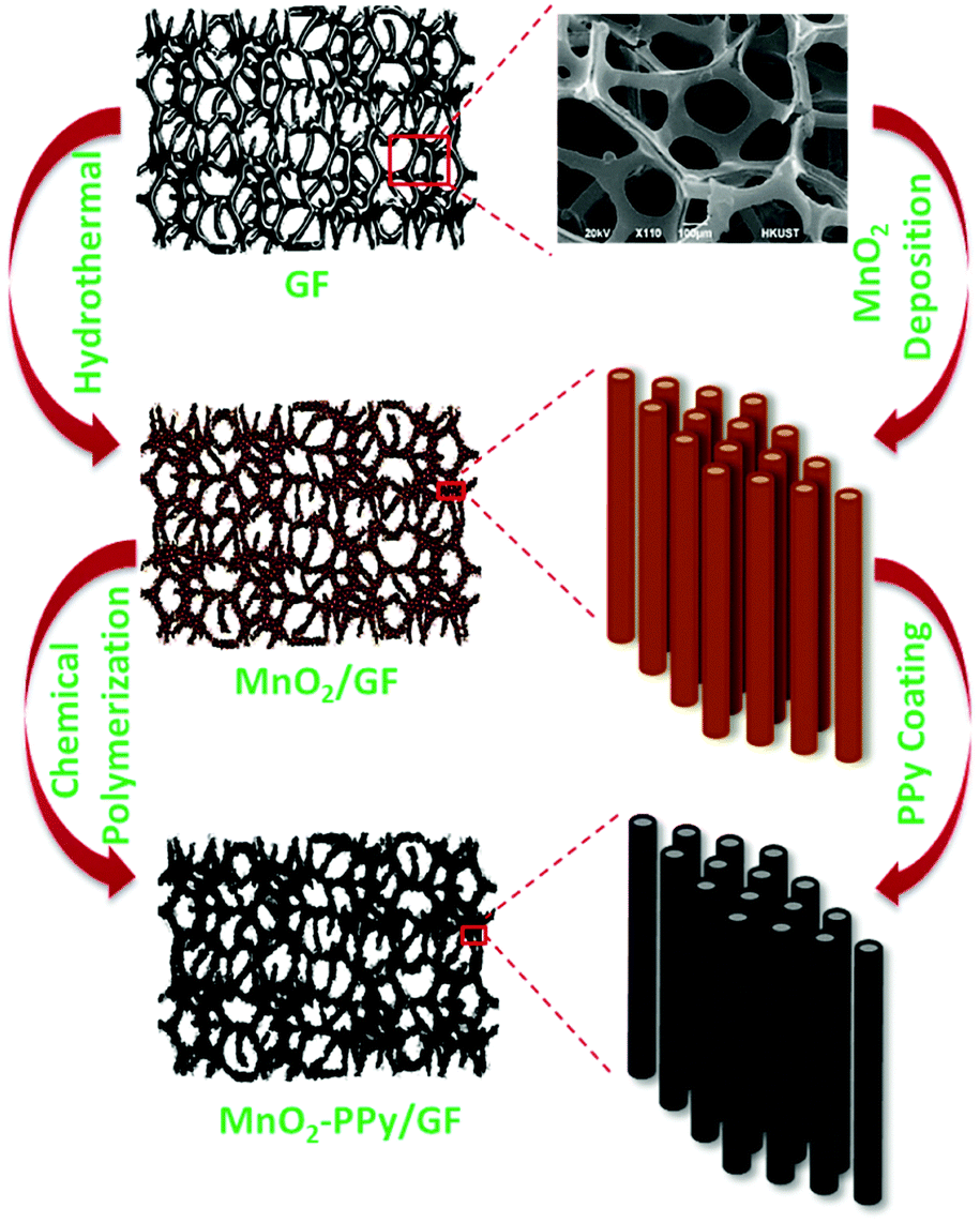 | ||
| Fig. 1 Schematic of the synthesis process of MnO2–PPy/GF. | ||
2.3. Materials characterization
The structure of the electrode was studied using a powder X-ray diffraction (XRD) system (PW1830, Philips) with Cu Kα radiation from 10° to 80°. The microstructural features and morphologies were examined by scanning electron microscopy (SEM, JEOL 6700), field emission transmission electron microscopy (FETEM, JEOL 2010), selected area electron diffraction (SAED) analysis and energy-dispersive X-ray spectroscopy (EDS). The PPy coating was characterized using Fourier transform infrared spectroscopy (FTIR, Perkin Elmer Spectrum One) in the 400–1800 cm−1 wavelength range. Both MnO2 and MnO2–PPy nanowires were mixed with potassium bromide (KBr) and pressed to prepare pellets. X-ray photoelectron spectroscopy (XPS, Surface analysis PHI5600, Physical Electronics) was used to evaluate the surface elemental compositions of the materials using the Al Kα line as the excitation source. A TGA/DTA 92 Setaram II testing system was utilized to perform the thermogravimetric analysis (TGA) in air over a temperature range of 50–800 °C at a heating rate of 10 °C min−1.2.4. Electrochemical measurements
CR2032 button cells were assembled in an Ar-filled glovebox with Li foil as the counter electrode, LiPF6 (1 M) in ethyl carbonate (EC)/dimethyl carbonate (DMC) (1![[thin space (1/6-em)]](https://www.rsc.org/images/entities/char_2009.gif) :1 by volume) as the electrolyte and a microporous polyethylene film (Celgard 2400) as the separator. The MnO2–PPy/GF composites synthesized above with an areal mass loading of 2 mg cm−2 were used directly as the positive electrode in a half-cell configuration. The cells were tested between 0 and 3 V at different current rates on a LAND 2001 CT battery tester. A CHI660 electrochemical workstation was used to conduct the cyclic voltammetry (CV) tests in the same potential window at a scan rate of 0.2 mV s−1. Electrochemical impedance spectroscopy (EIS) was performed in the frequency range from 0.01 Hz to 100 kHz on the same electrochemical workstation.
:1 by volume) as the electrolyte and a microporous polyethylene film (Celgard 2400) as the separator. The MnO2–PPy/GF composites synthesized above with an areal mass loading of 2 mg cm−2 were used directly as the positive electrode in a half-cell configuration. The cells were tested between 0 and 3 V at different current rates on a LAND 2001 CT battery tester. A CHI660 electrochemical workstation was used to conduct the cyclic voltammetry (CV) tests in the same potential window at a scan rate of 0.2 mV s−1. Electrochemical impedance spectroscopy (EIS) was performed in the frequency range from 0.01 Hz to 100 kHz on the same electrochemical workstation.
2.5. In situ TEM examination
The lithiation mechanism and the structural evolution of MnO2 nanowires as well as the influence of the PPy conductive coating on the lithiation behavior were studied in real time by in situ electrochemical experiments.24,25 The nanowires were loaded on a Cu wire tip as the working electrode while the Li metal was attached onto another Cu wire tip as the counter electrode on a scanning tunneling microscopy (STM) holder (Nanofactory®). The holder with the above nanocell was transferred to a TEM column (JEOL 2010) under the protection of an Ar gas flow. During the transfer, a Li2O film was formed on the counter electrode surface as a solid electrolyte interface (SEI) layer. To drive the diffusion of Li ions to the active material, a negative bias of −2 V was applied to the working electrode when it was in physical contact with the counter electrode, and the lithiation process was recorded using a high speed camera.3. Results and discussion
3.1. Structure and morphology
Fig. 2a shows the XRD patterns of MnO2/GF and MnO2–PPy/GF in comparison with neat MnO2, which was prepared under the same processing conditions. Two new peaks appeared at 2θ ≈ 26.5 and 54.7° in the spectra of the composites, which correspond to the reflections of the graphitic carbon (002) and (004) in the GF substrate, respectively,22,26 as indicated by the SEM and TEM images (Fig. S1, ESI†). All the other peaks for the composites are common with the neat MnO2 and are well fitted with pure α-MnO2 (JCPDS no. 00-044-0141): the peaks at ∼12.7, 18.1, 28.8, 37.5, 42, 49.9, 60.3 and 69.7° correspond to the (110), (200), (310), (211), (301), (411), (521) and (541) reflections, respectively. The SEM images of the MnO2/GF composites are shown in Fig. 2b and its inset, indicating a very uniform deposition of MnO2 nanowires on the surface of GF. They signify the desirable surface characteristics of GF that provided the sites required for nucleation and growth of MnO2 nanowires without agglomeration during the hydrothermal process. The TEM images in Fig. 2c and its inset present MnO2 nanowires with several micrometers in length and 20–50 nm in diameter, which are uniform from top to bottom. The HRTEM image and the fast Fourier transform (FFT) patterns in Fig. 2d present lattice fringes running along the wire direction with a reflection corresponding to the (200) plane and a d-spacing of 0.489 nm, typical of α-MnO2 single crystals, consistent with the XRD result. The α-MnO2 single crystal nanowires were formed by the redox reaction of KMnO4 in an acidic environment during the hydrothermal process according to the below equation:27–29| 3MnSO4 + 2KMnO4 + 2H2O → 5MnO2 + K2SO4 + 2H2SO4 | (1) |
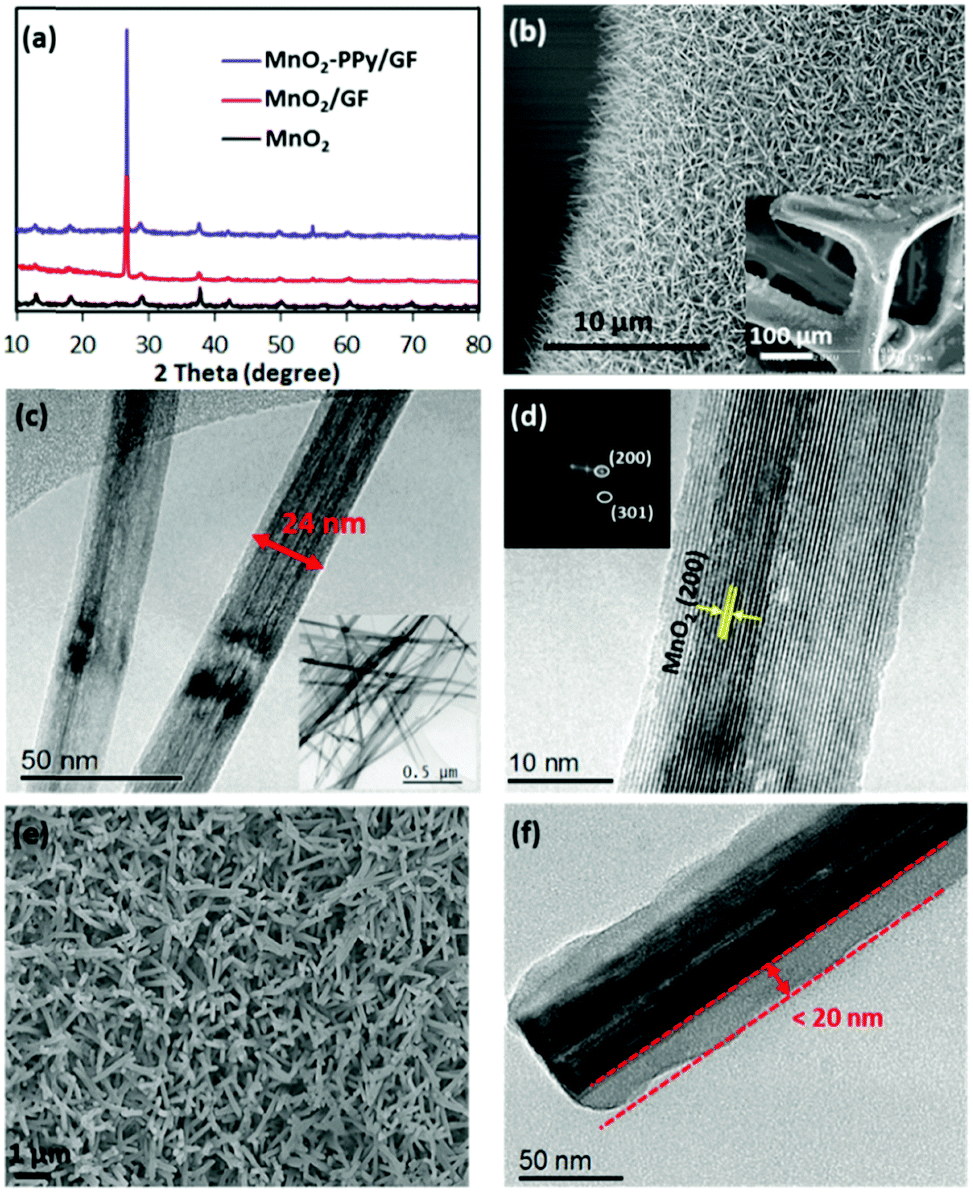 | ||
| Fig. 2 (a) XRD patterns of pure MnO2, MnO2/GF and MnO2–PPy/GF; (b) SEM image of MnO2/GF with a high magnification image in the inset; (c) TEM image of MnO2 nanowires with a low magnification image in the inset; (d) HRTEM image of a single crystal MnO2 nanowire with a FFT pattern of crystallographic planes in the inset; (e) SEM and (f) TEM image of the MnO2–PPy/GF composite. | ||
The SEM and TEM images of the MnO2–PPy/GF composite after PPy coating are shown in Fig. 2e and f. The TEM image reveals the PPy coating with a uniform thickness of ∼20 nm on the MnO2 nanowire surface. Because of the low temperature polymerization of PPy,33 the original microstructural features of MnO2 nanowires were maintained intact. The low temperature polymerization process is unique, facile and time-saving, which is different from the conventional carbon coating methods,24,34 where a further post-heat treatment was necessary for carbonization of the conductive polymer precursor at an elevated temperature, inevitably leading to phase transformation of the core material. The elemental maps and the energy-dispersive X-ray (EDS) spectrum present the distributions of Mn, O and C atoms (Fig. S2, ESI†), also confirming the core–shell structure of MnO2–PPy.
To determine the compositions of the PPy coating, MnO2 and GF in the composites, thermogravimetric analysis (TGA) was carried out in air, as shown in Fig. 3a. GF started to decompose at ∼600 °C,35 while PPy started to decompose at ∼200 °C in the PPy coated sample. According to the two curves, the weight fractions of PPy coating, MnO2 wires and GF in the MnO2–PPy/GF composite were estimated to be 12.6, 26.4 and 61 wt%, respectively. The FTIR spectra in Fig. 3b exhibit three prominent peaks located at 461, 519 and 617 cm−1 common to both MnO2 and MnO2–PPy nanowires, which are characteristic of the Mn–O vibrations of the MnO6 octahedra in the α-MnO2 crystals.36,37 Three new absorption bands appeared at 930, 1100 and 1191 cm−1, corresponding to the stretching vibrations of PPy in the MnO2–PPy composite.38 The peaks located at 785 and 966 cm−1 indicate the presence of polymerized pyrrole.39 The band at 1050 cm−1 is attributed to the C–H and N–H deforming vibrations, and the band located at 1559 cm−1 corresponds to the C![[double bond, length as m-dash]](https://www.rsc.org/images/entities/char_e001.gif) C/C–C stretching vibration of PPy rings.38
C/C–C stretching vibration of PPy rings.38
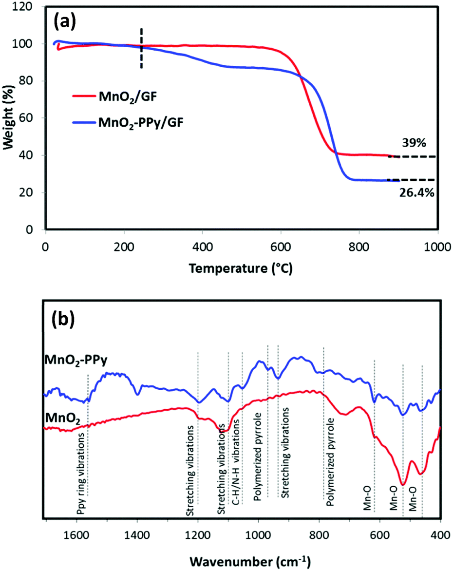 | ||
| Fig. 3 (a) TGA curves of MnO2/GF and MnO2–PPy/GF composites; and (b) FTIR spectra of MnO2 and MnO2–PPy. | ||
The XPS spectra were used to analyze the surface chemistries of MnO2/GF and MnO2–PPy/GF composites. Fig. 4a shows the deconvoluted XPS spectra of Mn 2p with two well-defined peaks at ∼642 and ∼654 eV in both composites, corresponding to the binding energies of Mn 2p1/2 and Mn 2p3/2, respectively.38 The deconvoluted O 1s XPS spectra of MnO2–PPy/GF in Fig. 4b show prominent peaks at 529.6, 531.2 and 532.5 eV which are attributed to the oxygen bonds in Mn–O–Mn, Mn–O–H and H–O–H (residual water), respectively.40 The extra peak at 533.8 eV corresponds to the CO bonds in PPy.41 All these peaks, except that for Mn–O–Mn, were negligible in MnO2/GF. The C 1s spectrum of MnO2/GF in Fig. 4c shows the characteristic peaks for GF at 284.4 and 285.6 eV, corresponding to the binding energies of C–C and C–H, respectively. The MnO2–PPy/GF composite exhibits four peaks at 284.4, 285.6, 287.5 and 288.9 eV attributed to the C–C, C–H, CN and CO bonds in PPy, respectively.42 The N 1s spectrum of MnO2–PPy/GF in Fig. 4d exhibits three peaks at 398.4, 400.3 and 401.1 eV, representing the imine (–CN–), neutral and amine (–NH–), and positively charged structures (–NH+–), respectively, confirming the presence of the PPy coating.43
 | ||
| Fig. 4 Deconvoluted XPS spectra of (a) Mn 2p, (b) O 1s and (c) C 1s for MnO2/GF (bottom curves in red) and MnO2–PPy/GF (top curves in blue) and (d) N 1s for the MnO2–PPy/GF composite. | ||
3.2. Electrochemical performance
Fig. 5a shows that the specific capacity of the MnO2–PPy/GF electrode after 150 cycles at a current density of 100 mA g−1 was 945 mA h g−1, which was significantly higher than 550 mA h g−1 for the MnO2/GF electrode. The corresponding charge/discharge profiles at different cycle numbers for the PPy coated electrode are shown in Fig. 5b, indicating an obvious plateau at a low potential of ∼0.35 V upon the first discharge with a specific capacity of 1249 mA h g−1. Although there was a large decrease in the 2nd charge capacity, the electrode became gradually stable in the following cycles to achieve an excellent specific capacity and a coulombic efficiency of over 98% for the entire 150 cycles. This observation signifies that the contribution of the PPy coating to the overall capacity was negligible in the first cycle, followed by gradual activation and kinetic stability of the electrode in the ensuing cycles. The rate performances of the two electrodes are shown in Fig. 5c. The MnO2–PPy/GF electrode exhibits specific capacities of 736, 593 and 430 mA h g−1 when tested at current densities of 0.2, 0.5 and 1 A g−1, respectively. Once the current density was reverted to 0.1 A g−1, it exhibited a high capacity of over 1000 mA h g−1 at the 100th cycle. Excellent stability was maintained for the rest of the cycles at 0.2 A g−1 with a reversible capacity of 780 mA h g−1 at the 200th cycle. The MnO2–PPy/GF electrodes outperformed by a large margin the MnO2/GF counterpart without a PPy coating at all current densities.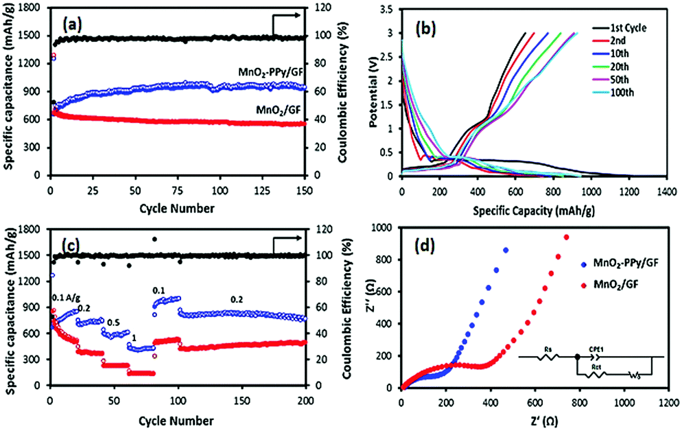 | ||
| Fig. 5 (a) Cycling performance of the electrodes at a current density of 0.1 A g−1, (b) discharge/charge profiles of the MnO2–PPy/GF electrode, (c) rate performance at different current densities and (d) Nyquist plots of the electrodes over the frequency range between 100 kHz and 0.01 Hz. | ||
To support the above findings, the electronic conductivity and the ion transfer behavior of the electrodes were studied using electrochemical impedance spectroscopy (EIS) and the Nyquist plots are shown in Fig. 5d. The corresponding impedance parameters were calculated using the Zview software. The Rs values, a measure of the electrolyte resistance and current collector/electrode contact resistance, were 13.7 and 7.7 Ω; and the Rct values, the kinetic resistance of charge transfer at the electrode/electrolyte interface, were 299.6 and 121.8 Ω for MnO2/GF and MnO2–PPy/GF, respectively. The over twice differences in these impedance parameters signify the importance of the high electronic conductivity associated with fast ion/electron transfer arising from the PPy coating, which in turn facilitated enhanced electrochemical performance of the MnO2–PPy/GF electrode.
The CV results shown in Fig. S3 (ESI†) indicate that the conversion reaction started at a potential below 0.4 V in the first lithiation process, characteristic of the electrochemical reduction of MnO2 according to eqn (2) and the formation of a SEI layer on the electrode surface. This observation is consistent with a long, stable plateau in the discharge profile (Fig. 5b). In the following delithiation process, two distinct peaks with two sloping plateaus were identified in the charge profile: one appeared at a low potential of ∼0.3 V assigned to delithiation of graphene foam4,44 and the other peak appeared at ∼1.2 V, corresponding to reversible oxidation of metallic Mn according to the reverse reaction of eqn (2).45,46
| MnO2 + 4Li+ + 4e− ↔ Mn + 2Li2O | (2) |
3.3. In situ microscopy
In order to gain a better understanding of the influence of the PPy coating on the electrochemical behavior and microstructural stability, an in situ TEM examination was performed to evaluate the microstructural evolution of the electrodes during the initial lithiation process. The results for the MnO2–PPy/GF and MnO2/GF electrodes are shown in Fig. 6 and Fig. S4 (ESI†), respectively (see the full video images from Movies 1 and 2, ESI†).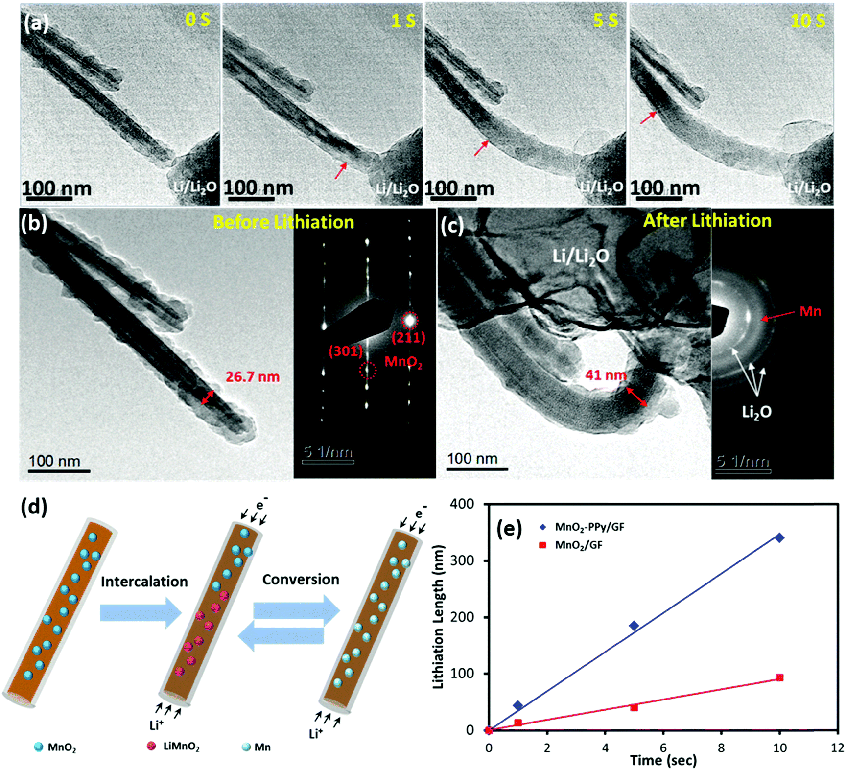 | ||
| Fig. 6 (a) Sequential in situ TEM images of the initial lithiation process of the MnO2–PPy nanowire; TEM images and SAED patterns of MnO2–PPy (b) before and (c) after complete lithiation; (d) schematic illustration of the full lithiation process of MnO2–PPy; (e) lithiation length measured at the initial stage versus time for MnO2 and MnO2–PPy nanowires. | ||
After −2 V was applied to the working electrode, Li ions started to propagate along the wire and initiated the conversion reactions with α-MnO2, as shown in Fig. 6a. For both electrodes, the original shapes of the wires were maintained even after complete lithiation, and no wire failure or cracking due to volume expansion or mechanical deformation was observed, indicating the mechanical robustness of the α-MnO2 nanowires against lithiation. The lithiation front was identified by the change in contrast (as marked with red arrows), which moved forwards in a uniform manner along the nanowire length with increasing time. According to the images taken before and after lithiation (Fig. 6b and c), the diameter of the α-MnO2 single crystal coated with PPy increased from 26.7 to 41.0 nm, equivalent to a linear expansion of ∼ 53.5%, after full lithiation. In contrast, the electrode without the PPy coating experienced a much larger linear expansion of ∼121.8% in diameter, as shown in Fig. S4a to c (ESI†). The considerable difference in linear expansion signifies how effectively the PPy coating prevented the large volumetric expansion of the electrode due to lithiation, which may be one of the most important reasons explaining the enhanced reversible capacities of the MnO2–PPy/GF composite electrode. The corresponding selected area electron diffraction (SAED) pattern taken from the unlithiated MnO2 was consistent with the XRD analysis, where three sharp ring patterns are related to the Li2O crystallographic planes. Another broad ring that freshly appeared after lithiation is attributed to the amorphous Mn, verifying the expected conversion reaction from the tunneling structure of α-MnO2 nanowires to amorphous Mn. The reversible conversion reactions based on the aforementioned discussion of CV curves (Fig. S3, ESI†), known information from the literature,46 and in situ TEM examinations (Fig. 6a–c and Fig. S4, ESI†), are schematically presented in Fig. 6d. The lithiation process took place according to eqn (2) in which Li+ ions first intercalated into the MnO2 crystals to produce an intermediate phase LiMnO2, followed by a conversion reaction to form amorphous Mn.46 During this process, the conductive PPy coating played an important role to buffer the volume expansion in the radial direction while accelerating the lithiation rate along the nanowire length. The conversion reaction was reversible, and thus the abovementioned reactions were reversed in the following delithiation process as confirmed by the CV results. The lithiation lengths (L) were measured along the electrode wires from the in situ TEM images and are plotted versus time (t) in Fig. 6e. Both electrodes exhibited a linear relationship between L and t, and the slopes of these lines represent the lithiation rate at the initial stage. An ultrafast lithiation rate of 34.2 nm s−1 was obtained for the α-MnO2–PPy, which is almost three-fold faster than 9.3 nm s−1 for the current, uncoated α-MnO2 and also much higher than 21.2 nm s−1 for similar α-MnO2 nanowires.46 This discovery reveals yet another ameliorating effect of the conductive PPy coating on reaction kinetics and ion/electron transport, which are directly relevant to the lithiation rate.
4. Conclusions
• Arrays of MnO2–PPy core–shell structures were synthesized on a conductive, cellular GF substrate via hydrothermal deposition of single crystal α-MnO2 nanowires, followed by a facile chemical polymerization of PPy to apply a thin coating on the nanowires.• The freestanding composite anode presented remarkable electrochemical performance for LIBs with excellent mechanical stability and a high capacity of 945 mA h g−1 after 150 cycles at 0.1 A g−1.
• A thin layer of conductive and compliant PPy on the MnO2 nanowires much enhanced the electrochemical performance of the electrode through a large increase in electronic conductivity as well as its capability to accommodate the volume expansion upon lithiation.
• The in situ TEM examination reveals that the MnO2–PPy nanowires were lithiated over three times faster than the neat MnO2 due to the ameliorating effect of the PPy coating on facilitating faster ion/electron transport along the wires, leading to a desirable augmentation in MnO2 conversion reaction kinetics. Moreover, the PPy coating played a critical role in buffering the volume expansion of the wire during lithiation to enhance its structural integrity, partly responsible for the exceptional electrochemical stability and reversibility of the electrode.
• MnO2 has been considered one of the most useful active materials for LIBs due to its natural abundance and low cost. However, the poor electrical conductivity and large volume expansion upon lithiation have limited its application as an anode in spite of its high theoretical capacity. The findings presented in this work shed new insights into how freestanding hybrid electrodes can be developed using MnO2 nanowires grown on a conductive 3D GF substrate for LIB applications as well as for other energy devices such as supercapacitors.
Conflicts of interest
The authors declare no competing financial interest.Acknowledgements
This project was financially supported by the Research Grants Council (GRF Project codes: 16212814, 16208718) and the Innovation and Technology Commission (ITF Project code: ITS/001/17) of Hong Kong SAR. The authors also appreciate the technical assistance from the Materials Characterization and Preparation Facilities (MCPF) and the Advanced Engineering Materials facilities (AEMF) at HKUST.References
- P. G. Bruce, S. A. Freunberger, L. J. Hardwick and J. M. Tarascon, Nat. Mater., 2012, 11, 19 CrossRef PubMed.
- B. Zhang, F. Kang, J. M. Tarascon and J. K. Kim, Prog. Mater. Sci., 2016, 76, 319 CrossRef.
- Z. L. Xu, X. M. Liu, Y. S. Luo, L. M. Zhou and J. K. Kim, Prog. Mater. Sci., 2017, 90, 1 CrossRef.
- J. Luo, J. Liu, Z. Zeng, C. F. Ng, L. Ma, H. Zhang, J. Lin, Z. Shen and H. Fan, Nano Lett., 2013, 13, 6136 CrossRef PubMed.
- M. Akbari Garakani, S. Abouali, B. Zhang, C. A. Takagi, Z. L. Xu, J. Q. Huang, J. Huang and J. K. Kim, ACS Appl. Mater. Interfaces, 2014, 6, 18971 Search PubMed.
- N. S. Spinner, A. Palmieri, N. Beauregard, L. Zhang, J. Campanella and W. E. Mustain, J. Power Sources, 2015, 276, 46 CrossRef.
- C. X. Guo, M. Wang, T. Chen, X. W. Lou and C. M. Li, Adv. Energy Mater., 2011, 1, 736 CrossRef.
- H. Lai, J. Li, Z. Chen and Z. Huang, ACS Appl. Mater. Interfaces, 2012, 4, 2325 Search PubMed.
- C. X. Guo, M. Wang, T. Chen, X. W. Lou and C. M. Li, Adv. Energy Mater., 2011, 1, 736 CrossRef.
- X. Zhang, T. Wang, C. Jiang, F. Zhang, W. Lia and Y. Tang, Electrochim. Acta, 2016, 187, 465 CrossRef.
- L. Li, A. R. O. Raji and J. M. Tour, Adv. Mater., 2013, 25, 6298 CrossRef PubMed.
- W. Mao, G. Ai, Y. Dai, Y. Fu, Y. Ma, S. Shi, R. Soe, X. Zhang, D. Qu, Z. Tang and V. S. Battaglia, J. Power Sources, 2016, 310, 54 CrossRef.
- C. Zhan, G. Yu, Y. Lu, L. Wang, E. Wujcik and S. Wei, J. Mater. Chem. C, 2017, 5, 1569 RSC.
- J. Liu, X. Xu, R. Hu, L. Yang and M. Zhu, Adv. Energy Mater., 2016, 6, 1600256 CrossRef.
- R. Warren, F. Sammoura, K. S. Teh, A. Kozinda, X. Zang and L. Lin, Sens. Actuators, A, 2015, 231, 65 CrossRef.
- F. Grote and Y. Lei, Nano Energy, 2014, 10, 63 CrossRef.
- P. Li, Y. Yang, E. Shi, Q. Shen, Y. Shang, S. Wu, J. Wei, K. Wang, H. Zhu, Q. Yuan, A. Cao and D. Wu, ACS Appl. Mater. Interfaces, 2014, 6, 5228 Search PubMed.
- J. Tao, N. Liu, W. Ma, L. Ding, L. Li, J. Su and Y. Gao, Sci. Rep., 2013, 3, 2286 CrossRef PubMed.
- C. Jiang, J. Wang, Z. Chen, Z. Yu, Z. Lin and Z. Zou, Electrochim. Acta, 2017, 245, 279 CrossRef.
- Y. Li, D. Ye, W. Liu, B. Shi, R. Guo, H. Pei and J. Xie, J. Colloid Interface Sci., 2017, 493, 241 CrossRef PubMed.
- L. Feng, Y. Zhang, R. Wang, Y. Zhang, W. Bai, S. Ji, Z. Xuan, J. Yang, Z. Zheng and H. Guan, Nanoscale Res. Lett., 2017, 12, 518 CrossRef PubMed.
- M. Akbari Garakani, S. Abouali, Z. L. Xu, J. Huang, J. Q. Huang and J. K. Kim, J. Mater. Chem. A, 2017, 5, 3547 Search PubMed.
- X. Sun, X. Liu, X. Shen, Y. Wu, Z. Wang and J. K. Kim, Composites, Part A, 2016, 85, 199 CrossRef.
- Z. L. Xu, K. Cao, S. Abouali, M. Akbari Garakani, J. Huang, J. Q. Huang, E. Kamali Heidari, H. Wang and J. K. Kim, Energy Stor. Mater., 2016, 3, 45 CrossRef.
- J. Cui, Z. L. Xu, S. Yao, J. Huang, J. Q. Huang, S. Abouali, M. Akbari Garakani, X. Ning and J. K. Kim, J. Mater. Chem. A, 2016, 4, 10964 Search PubMed.
- X. C. Dong, H. Xu, X. W. Wang, Y. X. Huang, M. B. C. Park, H. Zhang, L. H. Wang, W. Huang and P. Chen, ACS Nano, 2012, 6, 3206 CrossRef PubMed.
- X. Wang and Y. Li, Chem. Commun., 2002, 764 RSC.
- X. Wang and Y. Li, Chem. – Eur. J., 2003, 9, 300 CrossRef PubMed.
- M. H. Alfaruqi, J. Gim, S. Kim, J. Song, J. Jo, S. Kim, V. Mathew and J. Kim, J. Power Sources, 2015, 288, 320 CrossRef.
- Y. Chen, Y. Hong, Y. Ma and J. Li, J. Alloys Compd., 2010, 490, 331 CrossRef.
- Y. Yang, L. Xiao, Y. Zhao and F. Wang, Int. J. Electrochem. Sci., 2008, 3, 67 Search PubMed.
- Y. Yuan, A. Nie, G. M. Odegard, R. Xu, D. Zhou, S. Santhanagopalan, K. He, H. Asayesh-Ardakani, D. D. Meng, R. F. Klie, C. Johnson, J. Lu and R. Shahbazian-Yassar, Nano Lett., 2015, 15, 2998 CrossRef PubMed.
- D. Kong, W. Ren, C. Cheng, Y. Wang, Z. Huang and H. Y. Yang, ACS Appl. Mater. Interfaces, 2015, 7, 21334 Search PubMed.
- Q. Liu, S. Cao and Y. Qiu, Nano Energy, 2017, 42, 29274 CrossRef.
- P. Si, X. Dong, P. Chen and D. Kim, J. Mater. Chem. B, 2013, 1, 110 RSC.
- M. Zheng, H. Zhang, X. Gong, R. Xu, Y. Xiao, H. Dong, X. Liu and Y. Liu, Nanoscale Res. Lett., 2013, 8, 166 CrossRef PubMed.
- D. P. Dubal, D. S. Dhawale, R. R. Salunkhe and C. D. Lokhande, J. Electrochem. Soc., 2010, 157, A812 CrossRef.
- P. Gemeiner, J. Kulicek, M. Mikula, M. Hatala, L. Švorc, L. Hlavatá, M. Micušík and M. Omastová, Synth. Met., 2015, 210, 323 CrossRef.
- C. Xu, J. Sun and L. Gao, J. Mater. Chem., 2011, 21, 11253 RSC.
- J. G. Wang, Y. Yang, Z. H. Huang and F. Kang, J. Mater. Chem., 2012, 22, 16943 RSC.
- A. Singh, Z. Salmi, N. Joshi, P. Jha, A. Kumar, H. Lecoq, S. Lau, M. M. Chehimi, D. K. Aswal and S. K. Gupta, RSC Adv., 2013, 3, 5506 RSC.
- S. Bose, T. Kuila, M. E. Uddin, N. H. Kim, A. K. T. Lau and J. H. Lee, Polymer, 2010, 51, 5921 CrossRef.
- G. Han, Y. Liu, E. Kan, J. Tang, L. Zhang, H. Wang and W. Tang, RSC Adv., 2014, 4, 9898 RSC.
- A. P. Cohn, L. Oakes, R. Carter, S. Chatterjee, A. S. Westover, K. Share and C. L. Pint, Nanoscale, 2014, 6, 4669 RSC.
- A. L. M. Reddy, M. M. Shaijumon, S. R. Gowda and P. M. Ajayan, Nano Lett., 2009, 9, 1002 CrossRef PubMed.
- S. Y. Lee, L. Wu, A. S. Poyraz, J. Huang, A. C. Marschilok, K. J. Takeuchi, E. S. Takeuchi, M. Kim and Y. Zhu, Adv. Mater., 2017, 1703186 CrossRef PubMed.
Footnote |
| † Electronic supplementary information (ESI) available: GF characterization, EDS analysis, CV curves, in situ TEM images of a MnO2 nanowire and lithiation movies. See DOI: 10.1039/c8qm00153g |
| This journal is © the Partner Organisations 2018 |