Bioinspired magnetism-responsive hybrid microstructures with dynamic switching toward liquid droplet rolling states†
Yucheng
Bian‡
a,
Suwan
Zhu‡
a,
Xin
Li
*b,
Yuan
Tao
a,
Chenyu
Nian
a,
Chenchu
Zhang
c,
Yubin
Peng
d,
Chuanzong
Li
e,
Wei
Xiong
 f,
Wulin
Zhu
a,
Yanlei
Hu
 a,
Jiawen
Li
 a,
Jiaru
Chu
a and
Dong
Wu
 *a
*a
aCAS Key Laboratory of Mechanical Behavior and Design of Materials, Department of Precision Machinery and Precision Instrumentation, University of Science and Technology of China, Hefei, Anhui 230027, China. E-mail: dongwu@ustc.edu.cn
bState Key Laboratory of Pulsed Power Laser Technology College of Electronic Engineering, National University of Defense Technology, Hefei, Anhui 230000, China. E-mail: lixinkiller@nudt.edu.cn
cAnhui Province Key Lab of Aerospace Structural Parts Forming Technology and Equipment, Institute of Industry & Equipment Technology, Hefei University of Technology, Hefei, Anhui 230009, China
dSchool of Mechanical and Electrical Engineering, Anhui Jianzhu University, Hefei, Anhui 230601, China
eSchool of Computer and Information Engineering, Fuyang Normal University, Fuyang, Anhui 236037, China
fWuhan National Laboratory for Optoelectronics, Huazhong University of Science and Technology, Wuhan, Hubei 430074, China
First published on 12th June 2023
Abstract
The functionality of tunable liquid droplet adhesion is crucial for many applications such as self-cleaning surfaces and water collectors. However, it is still a challenge to achieve real-time and fast reversible switching between isotropic and anisotropic liquid droplet rolling states. Inspired by the surface topography on lotus leaves and rice leaves, herein we report a biomimetic hybrid surface with gradient magnetism-responsive micropillar/microplate arrays (GMRMA), featuring dynamic fast switching toward different droplet rolling states. The exceptional dynamic switching characteristics of GMRMA are visualized and attributed to the fast asymmetric deformation between the two different biomimetic microstructures under a magnetic field; they endow the rolling droplets with anisotropic interfacial resistance. Based on the exceptional morphology switching surface, we demonstrate the function of classification and screening of liquid droplets, and thus propose a new strategy for liquid mixing and potential microchemical reactions. It is expected that this intelligent GMRMA will be conducive to many engineering applications, such as microfluidic devices and microchemical reactors.
1. Introduction
Many plant leaves in nature exhibit superhydrophobicity,1–7 such as lotus leaves2–4 and rice leaves,4–6 whose surfaces are water-repellent due to the existence of numerous micro-nano structures. However, the rolling behavior of water droplets is usually distinct. For lotus leaves, the surface micro-nano structures are randomly and evenly distributed, so droplets have the same rolling angle along all directions, termed the isotropic rolling state.4 For rice leaves, the hybrid structures are unevenly distributed perpendicular to the direction of the veins, but evenly distributed parallel to the veins, so droplets are more likely to roll down along the vein's direction rather than the vertical direction, termed the anisotropic rolling state.4–6 This intriguing anisotropic property is fundamental to many engineering applications such as self-cleaning surfaces,5,6 water fog harvesting,11,12 and liquid manipulation.13,14 Accordingly, diverse artificial biomimetic surfaces with the anisotropic property are designed.7–15 For instance, Lu et al. prepared superhydrophobic multilevel microgrooves on polydimethylsiloxane (PDMS) films using a femtosecond laser and achieved efficient water collection;11 Liu et al. reported a superhydrophobic surface with anisotropic micro-patterns that realized guided self-propelled leaping of water droplets.13 However, these artificial surfaces can be classified into fixed structures with a non-adjustable anisotropic rolling state,11–15 which greatly limits their application scenarios.11–14Recently, intelligent surfaces with switchable isotropic/anisotropic droplet rolling states have been extensively reported, which are expected to overcome the limitation rooted in previous fixed surfaces.16–31 For example, Wang et al. reported a switchable surface with vertically and temporarily inclined microarrays using a shape memory polymer (SMP) for droplet transport and information storage;22 Li et al. prepared a SMP-based microcone array doped with iron powder particles for multifunctional droplet manipulation and could readily switch between vertical and curved states.26 Despite the advances in switching between isotropic and anisotropic rolling states using these strategies, dynamic liquid droplet control with fast response and no loss still remains a challenge. Most of the reported switchable surfaces require specific SMP materials to shift the surface morphology via their intrinsic shape memory property, such as polyurethane,16–20 epoxy resin,21–30 azobenzene polymers,31etc., which are usually assisted by heating–applying external force–cooling16–30 or light radiation31 and are unable to rapidly switch the surface state in real time. As a result, the materials preparation and regulation are rather complicated and high-cost.16–20,31 Moreover, most SMP materials are in the rigid form without flexibility at room temperature,21–30 which also severely limit their further utility in smart wearable devices.
Herein, we present a flexible gradient-magnetic-responsive surface composed of micropillar/microplate arrays. Inspired by the characteristic microstructures on lotus leaves and rice leaves, our dual-bioinspired platform was fabricated through femtosecond laser ablation and soft transfer technology using soft silicone materials,32–36 exhibiting the advantages of a low cost, flexible and deformable frame with fast magnetic driving modes. By adjusting the orientation of the surface micropillars using an external magnetic field, we achieved reversible and rapid switching between the lotus-leaf-like isotropic and rice-leaf-like anisotropic rolling states. Based on this reconfigurable droplet guiding platform, we demonstrated several typical applications, including sorting and screening liquid droplets and selective microchemical reactions at the interface. This work shows great potential in microfluidics, microchemical reactors, and other related fields.
2. Experimental
2.1. Materials
GMRMA consists of silica gel (Dragon skin 10 slow, Smooth-On, Inc., USA), two methyl silicone oil (PMX-200 1 cSt, Dow Corning, Inc., USA), and carbonyl iron powder (particle diameter ∼7 μm, >99.5% purity, Nangong Jianuo Metal Material Co., Ltd, China). The 1 mm thick polytetrafluoroethylene (PTFE) sheet used as the template material is commercially available.2.2. Preparation of GMRMA
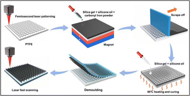
The fabrication process of GMRMA is shown in Fig. 1. The PTFE sheet was used as the mold, on which a regular array with adjacent microholes and microgrooves was fabricated through femtosecond laser one-step processing, and the femtosecond laser processing system (Spectra-physics Solstice Ace, MKS Instruments, Inc., USA) and optical path are shown in Fig. S1 (ESI†). The exit laser power was set as 500 mW. The sample was irradiated by vertically crossed line-by-line femtosecond laser scanning. The scanning spacing between two adjacent lines was 25 μm in both the x and y coordinate directions. The scanning speed was set as 5 mm s−1. The depths of the microholes and microgrooves are different and can be tuned with different laser ablation times independently. Then, a mixture containing liquid silicone, silicone oil, and carbonyl iron powder (10![[thin space (1/6-em)]](https://www.rsc.org/images/entities/char_2009.gif) :
:![[thin space (1/6-em)]](https://www.rsc.org/images/entities/char_2009.gif) 1
1![[thin space (1/6-em)]](https://www.rsc.org/images/entities/char_2009.gif) :
:![[thin space (1/6-em)]](https://www.rsc.org/images/entities/char_2009.gif) 11 by mass) was poured into the PTFE mold in a certain proportion and then fully deaerated in a vacuum chamber to ensure a complete infusion. To endow the samples with magnetic response, a neodymium–iron–boron (NdFeB) permanent magnet (100 × 50 × 10 mm3) was placed beneath the mold within 20 s. The excessive mixture on the mold was scraped off, on which a uniform mixture of liquid silicone and silicone oil (10
11 by mass) was poured into the PTFE mold in a certain proportion and then fully deaerated in a vacuum chamber to ensure a complete infusion. To endow the samples with magnetic response, a neodymium–iron–boron (NdFeB) permanent magnet (100 × 50 × 10 mm3) was placed beneath the mold within 20 s. The excessive mixture on the mold was scraped off, on which a uniform mixture of liquid silicone and silicone oil (10![[thin space (1/6-em)]](https://www.rsc.org/images/entities/char_2009.gif) :
:![[thin space (1/6-em)]](https://www.rsc.org/images/entities/char_2009.gif) 1 by mass) was evenly dropped and heated (60 °C, 0.5 h). The precursor of GMRMA was obtained by carefully peeling off the materials from the mold, whose surface wettability was influenced by the iron powder at the interfaces. Laser fast-scanning was employed to enhance the hydrophobicity on the samples in the last step, forming GMRMAs (Fig. S2, ESI†). Here, the exit laser power was 300 mW. The scanning spacing was 50 μm and the scanning speed was 50 mm s−1.
1 by mass) was evenly dropped and heated (60 °C, 0.5 h). The precursor of GMRMA was obtained by carefully peeling off the materials from the mold, whose surface wettability was influenced by the iron powder at the interfaces. Laser fast-scanning was employed to enhance the hydrophobicity on the samples in the last step, forming GMRMAs (Fig. S2, ESI†). Here, the exit laser power was 300 mW. The scanning spacing was 50 μm and the scanning speed was 50 mm s−1.
2.3. Characterization
The surface morphology was characterized by secondary scanning electron microscopy (SEM, EVO18, Carl Zeiss AG, Germany). Some photos were taken with industrial cameras (YW500, Mindvision Technology Co., Ltd, China). The dynamic contact angle was measured with an optical contact angle meter (innuo CA100C, Shanghai Innuo Precision Instrument Co., Ltd, China) based on a 10 μL droplet. Five trials were performed in different locations for each experiment. The magnetic flux density near the permanent magnet was simulated using COMSOL software.3. Results and discussion
3.1. Surface morphology and magnetic response of GMRMA
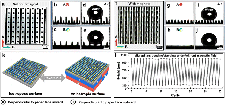
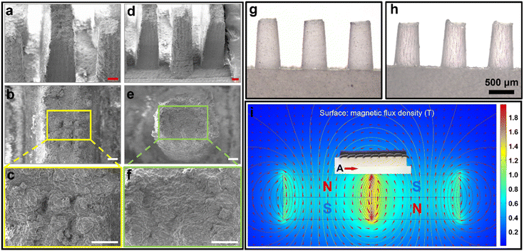
Fig. 2a–c show the surface morphology of GMRMA without a magnetic field at different viewing angles. The micropillars exhibited the isotropic state along two orthogonal directions of A and B, while the microplates exhibited the anisotropic state along the two directions. Fig. 2d and e display the sample wetting states of a 10 μL water droplet observed along the two directions, respectively. The droplets were solely supported by the isotropic micropillars. When a magnetic field was applied, the micropillars bent anisotropically in A and B directions, while the microplates remained anisotropic (Fig. 2f–h). In this case, the droplets contacted both the bent micropillars and microplates (Fig. 2i and j). As sketched in Fig. 2k, the on/off switching of a magnetic field could adjust the bending states of the micropillars, realizing an isotropic/anisotropic pattern shift. This switchable property showed a favorable reproducibility during 30 cycles by alternating on/off states of a magnetic field (Fig. 2l).The surface morphology of GMRMA was investigated by scanning electron microscopy (SEM, Fig. 3a–f). Fig. 3a–c show the top and side views of the microplates, while Fig. 3d–f are the top and side views of the micropillars. SEM images show a complex micro-nano structure on the micropillars and microplates, facilitating the rolling and transport of microdroplets on GMRMA. Besides, the iron powder was randomly distributed inside the micropillars without a magnetic field (Fig. 3g). In contrast, the introduction of neodymium–iron–boron magnets could effectively orient and arrange the iron powder particles into chains along the magnetic field lines,31 as evidenced in Fig. 3h. To better visualize the iron particles inside the samples, here the mass ratio of iron powder was reduced to 1%. In the magnetization process, two permanent magnets (20 × 20 × 10 mm3) were combined to generate an enhanced magnetic field (Fig. S3, ESI†), and the actual magnetic flux density was measured as ∼400 mT in the vicinity of the bent micropillars. The magnetic field distribution around a GMRMA was simulated and is shown in Fig. 3i. It is observed that the micropillars above the center of the magnet cluster bent along the magnetic lines of force, while the microplates showed no significant response.
When the GMRMA transformed from the isotropic state to the anisotropic state, the equivalent magnetic force and conversion time were quantified (Fig. S4, ESI†). A typical seven-micropillar array completely bent at t ≈ 91.3 ms, showing a relatively fast response at 400 mT magnetic flux density. To estimate the equivalent magnetic force that deforms the micropillars, an increasing pressure was loaded on the upper surface of a 15 × 8 micropillar array. The total bending force was measured as ∼0.43 N, indicating a transition force of approximately 3.58 mN on a single micropillar.
3.2. Influence of diverse geometric parameters on droplet rolling performance
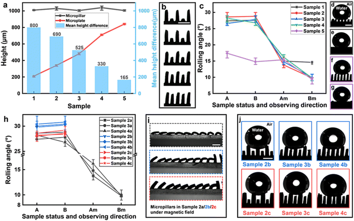
To endow the hybrid microstructures with isotropic/anisotropic switching toward the rolling states of droplets, the height of the magnetism-responsive micropillars should be greater than that of the irresponsive microplates when no magnetic field is applied. The height difference between the micropillars and microplates is crucial in the sample preparation, i.e., a smaller or larger height difference would destroy the isotropic/anisotropic switching capability along A and B directions. To quantify its influence on the droplet rolling performance, the micropillar height was fixed at 1 mm. We defined the samples 1 to 5 by an increasing microplate height (Fig. 4a and b). The micropillar diameter and the microplate thickness were fixed at 300 μm and the distance between the micropillars and microplates was fixed at 500 μm. The rolling experiments are shown in Fig. 4c, where A and B represent the observing directions of the droplets on the sample without a magnetic field, Am and Bm are the observing directions in a magnetic field, and the observing direction is perpendicular to the droplet rolling direction. It is observed that sample 2 exhibited the best isotropic/anisotropic switching performance of droplet rolling states in an on/off alternating magnetic field, while samples 3 and 4 showed favorable dynamic switching performance as the magnetic field was on. No significant rolling state transition was found in sample 1 because the height of the bent micropillars was very close to the microplates in a magnetic field. In this case, the bent micropillars filled the gaps between adjacent microplates and reduced the gap size, followed by the decrease of energy barrier at the droplet–structure interface,11,37 leading to the decreased rolling angles of water droplets along direction B of sample 1 (Fig. 4d and e). In addition, sample 5 exhibited poor isotropic performance when the magnetic field was not applied. It is because the height difference between the micropillars and microplates was small, and the droplets contacted both the tops of the microplates and micropillars, destroying the isotropic wettability along the two directions (Fig. 4f and g). The detailed interfacial contact configurations are found in Fig. S5, ESI.†Going further, the influence of the micropillar diameter on the wettability switching was subsequently investigated. Based on the sample performance above, we chose samples 2, 3, and 4 with a variable micropillar diameter of 100, 200, 300, 400, and 500 μm. However, it is hard to keep a uniform and vertical configuration of the micropillars due to the flexibility of silicone gel with larger aspect ratios for the samples with 100 μm and 200 μm diameters. Hence, nine samples (samples 2a–4c) were quantified with the micropillar diameters of 300 μm, 400 μm, and 500 μm, respectively (Fig. 4h). The samples with diameters of 400 μm and 500 μm bent inconsistently under the magnetic field, leading to an irregular switching of the droplet rolling state (Fig. 4i). Moreover, with an increasing micropillar diameter of up to 500 μm, the contact state of a 10 μL droplet on the samples changed (Fig. 4j). The number of supporting micropillars decreased, resulting in a smaller contact area and rolling angle (Fig. 4h). As a result, the samples with a micropillar diameter of 300 μm manifested the best performance in dynamic switching toward droplet rolling states.
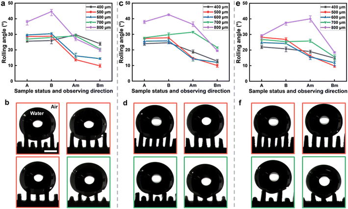
As another important metric, the spacing between micropillars and microplates was also investigated. Here, we chose samples 2 (height difference ∼690 μm, Fig. 5a), 3 (∼525 μm, Fig. 5c) and 4 (∼330 μm, Fig. 5e) with a fixed micropillar diameter and microplate thickness of 300 μm. Fig. 5b, d, and f show several typical contact interfaces between water droplets and GMRMAs in direction A, where the red and green boxes correspond to a magnetic field off/on, respectively. The spacings were set as 400, 500, 600, 700, and 800 μm, respectively. It is shown that sample 2 with a spacing of 500 μm performed the best in the isotropic/anisotropic switching of droplet rolling states. For an increased spacing of 800 μm, all the samples exhibited significant anisotropic rolling behaviors no matter whether a magnetic field was applied or not. Besides, when the magnetic field was off, the isotropic rolling property weakened as the spacing increased. This is because the droplet gradually “embedded” into the structures, coming into contact with the underlying microplates with the destruction of isotropy (Fig. 5b). However, in Fig. 5d and f, due to the smaller height difference, the droplets always came into contact with the microplates, forming an anisotropic wetting state on the hybrid structures. When the magnetic field was on, the droplets gradually came into contact with the bent micropillars, triggering the rolling anisotropy between the A and B directions.
We also briefly investigated the impact of droplet size (volume) and magnetic flux density on GMRMA anisotropy (Fig. S6, ESI†). According to our previous optimized geometric parameters, here the mean height difference and the distance between micropillars and microplates were chosen as 690 and 500 μm, respectively. The micropillar diameter and the microplate thickness were set as 300 μm. It is shown that GMRMA exhibited a favorable tolerance toward the isotropic/anisotropic droplet rolling shift in the range from 6 to 14 μL. In addition, a minimum flux density of ∼100 mT was observed during the micropillar bending process. At this stage, GMRMA started to show droplet rolling anisotropy. When the magnetic flux density exceeded ∼240 mT, the bent micropillars became lower than the microplates. The droplet rolling anisotropy tended to be stable and finally reached extrema after 300 mT.
3.3. Mechanism of the wettability-switchable surface
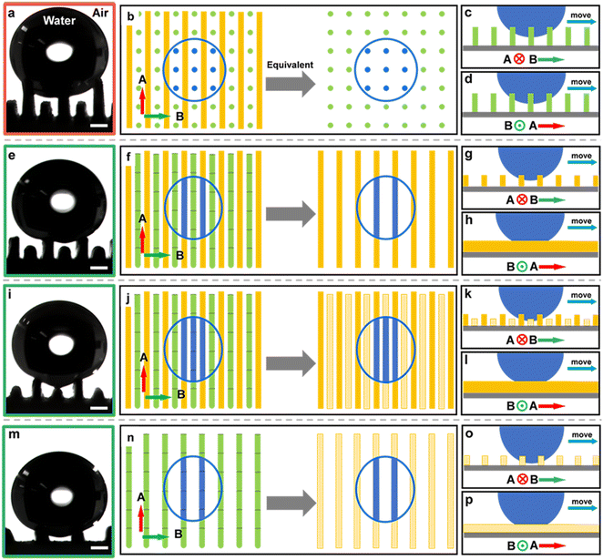
The underlying mechanism of the wettability-switchable surface is briefly discussed by looking into the interfacial configurations between the droplets and GMRMAs. A typical interfacial configuration with the isotropic rolling state is shown in Fig. 6a, others with the anisotropic rolling state are shown in Fig. 6e and i. The blue circles represent the outline of a droplet on each sample. Specifically, when no magnetic field was applied, the droplet was solely supported by the micropillars. In this case, the interface is equivalent to a micropillar array distributed uniformly along the A and B directions (Fig. 6b). As a result, the contact configuration of droplet–micropillar is identical along the two directions. So, the rolling droplets along the two directions possess the same three-phase contact lines and energy barriers.37,38 When the magnetic field was applied and the micropillars bent, the interfacial configurations could be divided into two phases. In the phase of Fig. 6e, the microplates were higher than the bent micropillars, and the droplet was solely supported by the microplates. Thus, the interface is equivalent to a microplate array with distinct morphology along the A and B directions (Fig. 6f). The section of the solid–liquid interface remains unchanged along direction A but varies periodically along direction B, resulting in an elevated energy barrier for a rolling droplet across the microplate gaps (Fig. 6g and h).11,37 Hence, the rolling angle in direction B is greater than that in direction A,38,39 and thus the sample exhibits anisotropic wetting characteristics. In another phase in Fig. 6i, the water droplet was supported by both the microplates and the bent micropillars because the microplates were slightly lower than those in Fig. 6e. Thus, the continuous bent micropillars could be simplified into low-height microplates, which together with the original microplates formed a new hybrid microplate array (Fig. 6j). The deformed hybrid structures, similar to those on a rice leaf (Fig. 6k and l), still exhibited anisotropic rolling states along the two directions but possessed different three-phase contact lines and energy barriers compared with the cases in Fig. 6g and h. In addition to the rolling angle difference, the static contact angle variation on two typical samples (samples 2 and 3) was also investigated (Fig. S7, ESI†). It is observed that the difference of static contact angles along A and B directions enlarged for both samples as the magnetic field was applied, which in turn validated the enlarged anisotropic energy barriers along the two orthogonal directions.To clarify whether the structure of pure micropillars has droplet directional rolling selectivity, we have conducted a contrast experiment by preparing a new platform consisting of a single micropillar array with a fixed height and spacing of 1 mm. The micropillar diameter was 300 μm. According to Fig. 6m–p, the micropillar array transformed into a lower “microplates” array as the magnetic force was applied. Meanwhile, the rolling droplets also exhibited different contact patterns/energy barriers in A and B directions (also evidenced in Fig. S8, ESI†), indicating that the droplet rolling anisotropy mainly stemmed from the magnetism-induced bending micropillars on GMRMA.
3.4. Applications based on the rolling state switching ability of GMRMA
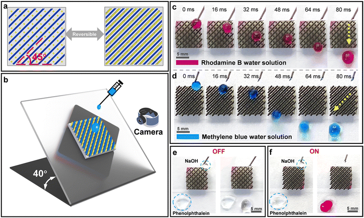
Finally, relying on the switchable dual-bioinspired surface with fast magnetic response, we demonstrated typical microfluidic applications, including sorting and screening different droplets and selective microchemical reactions at the interface. A 1 × 1 cm2 tailor-made sample with hybrid microstructures was prepared in a tilted 45° orientation (Fig. 7a) and then placed on a tilted platform at 40°. By applying and removing the magnet cluster on the back, the selection and guidance of the droplets could be achieved (Fig. 7b and Fig. S9, ESI†). When the magnetic field was off, the micropillars were upright, forming an isotropic rolling surface. The Rhodamine B droplet rolled down the sample vertically without changing its motion direction (Fig. 7c and Video S1†). When the magnetic field was on, the micropillars bent along the direction of the microplates, forming an anisotropic rolling surface. The hybrid structure consisting of the microplates and the bent micropillars created an impassable energy barrier perpendicular to the droplet motion direction. The methylene blue droplet from the upper right rolled off along the 45° inclined microgroove and finally fell to the lower left of the sample (Fig. 7d and Video S1†). The selective microchemical reactions are shown in Fig. 7e and f. The NaOH solution droplet rolled down vertically without reacting with the phenolphthalein solution as the magnetic field was off. When the magnetic field was on, the alkaline droplet rolled down to the lower left corner and reacted with the phenolphthalein, and the color immediately turned purple-red (Video S2†). This demonstration highlights the promise of our intriguing bioinspired functional surfaces for droplet management and controllable microchemical reactions.4. Conclusions
In summary, we designed a dual-biomimetic hybrid surface with fast magnetic response inspired by the unique microstructures on the lotus leaves and the rice leaves through femtosecond laser direct writing and transfer printing methods. The surface morphology of GMRMA could be dynamically switched between isotropic and anisotropic rolling states toward liquid droplets under a magnetic field. The key parameters that influence the droplet rolling behaviors on this platform were further quantified along two orthogonal directions with an alternating magnetic field, including the micropillar diameter, the height difference, and the spacing between micropillars and microplates. It is revealed that the fast real-time switching of wettability stems from the fast asymmetric deformation of two distinct biomimetic microstructures as the magnetic field is applied, which in turn creates the anisotropic energy barriers at the droplet–GMRMA interface along two orthogonal directions. Based on the reversible, lossless and fast switching capability of rolling states for droplets on GMRMA, we elaborately constructed a reconfigurable micro-droplet guiding system and demonstrated the typical function of classification and screening of liquid droplets toward visualized liquid mixing and microchemical reactions. This dual-biomimetic versatile platform should find use in applications that call for fast liquid screening and mixing, for example in microfluidic devices or in microchemical reactors.Author contributions
Dong Wu and Xin Li conceived the idea. Yucheng Bian wrote the manuscript text and designed the experimental device. Yucheng Bian and Suwan Zhu performed the experiments. Yuan Tao and Chenyu Nian participated in the material selection and material preparation. Chenchu Zhang, Yubin Peng, Chuanzong Li, and Wulin Zhu provided assistance in data analysis and characterization. Wei Xiong, Yanlei Hu, Jiawen Li, and Jiaru Chu participated in the discussion of experimental results and manuscript revision. All authors reviewed the manuscript.Conflicts of interest
There are no conflicts to declare.Acknowledgements
This work was supported by the National Natural Science Foundation of China (No. 61927814, 52122511, 52075516, 62105090, U20A20290), the Natural Science Foundation of Anhui Province (2208085QE156), the National Key Research and Development Program of China (No. 2021YFF0502700), the Open Research Fund of State Key Laboratory of Pulsed Power Laser Technology (SKL2021KF06), the Open Project of Wuhan National Laboratory for Optoelectronics (2019WNLOKF014), and the Students’ Innovation and Entrepreneurship Foundation of USTC (No. XY2022G02CY, CY2022G32). We acknowledge the Experimental Center of Engineering and Material Sciences at USTC for the fabrication and measurement of samples. This work was partly carried out at the USTC Center for Micro and Nanoscale Research and Fabrication.References
- M. Liu, S. Wang and L. Jiang, Nat. Rev. Mater., 2017, 2, 1–17 CrossRef.
- W. Barthlott and C. Neinhuis, Planta, 1997, 202, 1–8 CrossRef CAS.
- X. Zhang, F. Shi, J. Niu, Y. Jiang and Z. Wang, J. Mater. Chem., 2008, 18, 621–633 RSC.
- L. Feng, S. Li, Y. Li, H. Li, L. Zhang, J. Zhai, Y. Song, B. Liu, L. Jiang and D. Zhu, Adv. Mater., 2002, 14, 1857–1860 CrossRef CAS.
- S. Li, J. Huang, Z. Chen, G. Chen and Y. Lai, J. Mater. Chem. A, 2017, 5, 31–55 RSC.
- D. Xia, L. M. Johnson and G. P. López, Adv. Mater., 2012, 24, 1287–1302 CrossRef CAS PubMed.
- S. Wang, K. Liu, X. Yao and L. Jiang, Chem. Rev., 2015, 115, 8230–8293 CrossRef CAS PubMed.
- T. Jiang, Z. Guo and W. Liu, J. Mater. Chem. A, 2015, 3, 1811–1827 RSC.
- P. Ragesh, V. A. Ganesh, S. V. Nair and A. S. Nair, J. Mater. Chem. A, 2014, 2, 14773–14797 RSC.
- T. Darmanin and F. Guittard, J. Mater. Chem. A, 2014, 2, 16319–16359 RSC.
- Y. Lu, L. Yu, Z. Zhang, S. Wu, G. Li, P. Wu, Y. Hu, J. Li, J. Chu and D. Wu, RSC Adv., 2017, 7, 11170–11179 RSC.
- X. Dai, N. Sun, S. O. Nielsen, B. B. Stogin, J. Wang, S. Yang and T.-S. Wong, Sci. Adv., 2018, 4, eaaq0919 CrossRef PubMed.
- J. Liu, H. Guo, B. Zhang, S. Qiao, M. Shao, X. Zhang, X. Q. Feng, Q. Li, Y. Song and L. Jiang, Angew. Chem., Int. Ed., 2016, 55, 4265–4269 CrossRef CAS PubMed.
- S. M. Kang, C. Lee, H. N. Kim, B. J. Lee, J. E. Lee, M. K. Kwak and K. Y. Suh, Adv. Mater., 2013, 25, 5756–5761 CrossRef CAS PubMed.
- D. Wu, J. N. Wang, S. Z. Wu, Q. D. Chen, S. Zhao, H. Zhang, H. B. Sun and L. Jiang, Adv. Funct. Mater., 2011, 21, 2927–2932 CrossRef CAS.
- Y. Wang, H. Lai, Z. Cheng, H. Zhang, E. Zhang, T. Lv, Y. Liu and L. Jiang, Nanoscale, 2019, 11, 8984–8993 RSC.
- Y. Shao, W. Du, Y. Fan, J. Zhao, Z. Zhang and L. Ren, Chem. Eng. J., 2022, 427, 131718 CrossRef CAS.
- Y. Wang, X. Yu, Z. Cheng, C. Zhi, Y. Liu and Y. Liu, Composites, Part A, 2021, 149, 106579 CrossRef CAS.
- Y. Shao, H. Dou, P. Tao, R. Jiang, Y. Fan, Y. Jiang, J. Zhao, Z. Zhang, T. Yue and S. N. Gorb, ACS Appl. Mater. Interfaces, 2022, 14, 17995–18003 CrossRef CAS PubMed.
- Y. Shao, J. Zhao, Y. Fan, Z. Wan, L. Lu, Z. Zhang, W. Ming and L. Ren, Chem. Eng. J., 2020, 382, 122989 CrossRef CAS.
- C. Li, Y. Jiao, D. Li, L. Li, Y. Peng, S. Jiang, Y. Zhang, C. Zhang, S. Fan and Q. Song, Appl. Phys. Lett., 2022, 120, 061603 CrossRef CAS.
- W. Wang, H. Lai, Z. Cheng, Z. Fan, D. Zhang, J. Wang, S. Yu, Z. Xie and Y. Liu, ACS Appl. Mater. Interfaces, 2020, 12, 49219–49226 CrossRef CAS PubMed.
- Y. Song, H. Lai, X. Jiao, Z. Cheng, H. Kang, D. Zhang, Z. Fan, Z. Xie, Y. Wang and Y. Liu, Adv. Compos. Hybrid Mater., 2022, 5, 788–797 CrossRef CAS.
- C. Li, Y. Jiao, X. Lv, S. Wu, C. Chen, Y. Zhang, J. Li, Y. Hu, D. Wu and J. Chu, ACS Appl. Mater. Interfaces, 2020, 12, 13464–13472 CrossRef CAS PubMed.
- H. Wang, Z. Zhang, J. Zheng, J. Zhao, Y. Liang, X. Li and L. Ren, Chem. Eng. J., 2021, 417, 127944 CrossRef CAS.
- C. Li, Y. Jiao, Y. Zhang, S. Jiang, X. Lv, S. Wu, J. Li, Y. Hu, J. Ye and K. Liu, Adv. Funct. Mater., 2021, 31, 2100543 CrossRef CAS.
- X. Luo, H. Lai, Z. Cheng, P. Liu, Y. Li, X. Yu and Y. Liu, Chem. Eng. J., 2021, 403, 126356 CrossRef CAS.
- X. Bai, Q. Yang, Y. Fang, J. Zhang, J. Yong, X. Hou and F. Chen, Chem. Eng. J., 2020, 383, 123143 CrossRef CAS.
- Z. Cheng, D. Zhang, T. Lv, H. Lai, E. Zhang, H. Kang, Y. Wang, P. Liu, Y. Liu and Y. Du, Adv. Funct. Mater., 2018, 28, 1705002 CrossRef.
- X. Bai, J. Yong, C. Shan, Y. Fang, X. Hou and F. Chen, Sci. China: Chem., 2021, 64, 861–872 CrossRef CAS.
- X. Yang, H. Jin, X. Tao, B. Xu and S. Lin, Polym. Chem., 2021, 12, 5303–5309 RSC.
- S. Jiang, Y. Hu, H. Wu, Y. Zhang, Y. Zhang, Y. Wang, Y. Zhang, W. Zhu, J. Li and D. Wu, Adv. Mater., 2019, 31, 1807507 CrossRef PubMed.
- S. Jiang, Y. Hu, H. Wu, R. Li, Y. Zhang, C. Chen, C. Xue, B. Xu, W. Zhu and J. Li, Nano Lett., 2020, 20, 7519–7529 CrossRef CAS PubMed.
- Z.-Z. Li, L. Wang, H. Fan, Y.-H. Yu, Q.-D. Chen, S. Juodkazis and H.-B. Sun, Light: Sci. Appl., 2020, 9, 41 CrossRef CAS PubMed.
- M. Malinauskas, A. Žukauskas, S. Hasegawa, Y. Hayasaki, V. Mizeikis, R. Buividas and S. Juodkazis, Light: Sci. Appl., 2016, 5, e16133–e16133 CrossRef CAS PubMed.
- K. Sugioka and Y. Cheng, Light: Sci. Appl., 2014, 3, e149–e149 CrossRef CAS.
- J. P. Youngblood and T. J. McCarthy, Macromolecules, 1999, 32, 6800–6806 CrossRef CAS.
- Z. Yoshimitsu, A. Nakajima, T. Watanabe and K. Hashimoto, Langmuir, 2002, 18, 5818–5822 CrossRef CAS.
- S. G. Lee, H. S. Lim, D. Y. Lee, D. Kwak and K. Cho, Adv. Funct. Mater., 2013, 23, 547–553 CrossRef CAS.
Footnotes |
| † Electronic supplementary information (ESI) available. See DOI: https://doi.org/10.1039/d3nr02082g |
| ‡ These authors contributed equally. |
| This journal is © The Royal Society of Chemistry 2023 |

