Strain-tunable skyrmions in two-dimensional monolayer Janus magnets
Yue-tong
Han
 ,
Wei-xiao
Ji
 ,
Pei-Ji
Wang
 ,
Ping
Li
and
Chang-Wen
Zhang
*
School of Physics and Technology, University of Jinan, Jinan, Shandong 250022, People's Republic of China. E-mail: ss_zhangchw@ujn.edu.cn
First published on 13th March 2023
Abstract
The Dzyaloshinskii–Moriya interaction (DMI), which only exists in noncentrosymmetric systems, plays an important role in the formation of exotic chiral magnetic states. However, the absence of the DMI occurs in most two-dimensional (2D) magnetic materials due to their intrinsic inversion symmetry. Here, by using first-principles calculations, we demonstrate that a significant DMI can be obtained in a series of Janus monolayers of dichalcogenides XSeTe (X = Nb, Re) in which the difference between Se and Te on the opposite sides of X breaks the inversion symmetry. Remarkably, the DMI amplitudes of NbSeTe (1.78 meV) and ReSeTe (4.82 meV) are larger than the experimental value of Co/graphene (0.16 meV), and NbSeTe and ReSeTe monolayers have a high Curie temperature of 1023 K and 689 K, respectively. Through the micromagnetic simulation of XSeTe (X= Nb, Re) simulations, we also find that the ReSeTe monolayer can performance for skyrmion states by applying an external magnetic field, and importantly, the skyrmion states can be regulated and controlled under external strain. The findings pave the way for device concepts using chiral magnetic structures in specially designed 2D ferromagnetic materials.
Chiral magnetic structures such as chiral domain walls,1,2 helical structures,3,4 and magnetic skyrmions5–7 hold promise for potential application in future spintronic devices. Microscopically, the Dzyaloshinskii–Moriya interaction (DMI), which favors canted spin configurations, plays an essential role in the formation of such noncollinear magnetic nanostructures. For the presence of DMI, in addition to strong spin–orbit coupling (SOC) and magnetism, the system is required to have a broken inversion symmetry.8,9 Therefore, a significant DMI typically arises in noncentrosymmetric bulk magnets10–12 and at interfaces13,14 between a ferromagnet and an adjacent layer with strong SOC. Notably, much effort has been devoted to growing multilayer stacks of ferromagnet/heavy metal FM/HM heterostructures (HTSs), e.g., Ir/Co/Pt,15 Ir/Fe/Co/Pt,16 and Pt/Co/MgO17 multilayers, in order to enhance the interfacial DMI.18
Two-dimensional (2D) magnets, which integrate the ideal interface, miniaturization, and long-sought magnetism, provide a fascinating platform for the spintronics research.19–23 Some exciting phenomena, such as huge tunneling magnetoresistance,24 long-distance magnon transport,25 and magnetization switching driven by spin–orbital torque (SOT), have been realized in 2D magnet-based devices with low energy consumption, high thermal stability, and high storage density.26–29 Therefore, tremendous efforts have been devoted to searching intrinsic 2D magnets with high temperature TC and large perpendicular magnetic anisotropy (PMA), or an effective method which can enhance these properties.30–32 Moreover, through breaking the inversion symmetry of 2D magnets, especially by constructing the Janus structure, a sizable DMI can be obtained. As an asymmetric exchange interaction induced by SOC,33,34 the DMI favors the formation of chiral magnetic structures, such as chiral domain walls and skyrmions, which can be manipulated by small electrical currents and are promising for spintronics applications in the midterm future. Furthermore, since 2D magnets can be integrated into various HTSs, the chiral spin textures are hopefully tuned by proximity effects.
Recent experiments have demonstrated that Janus monolayers (MLs) of transition metal dichalcogenides (TMDs), e.g. MoSSe,8,35 can be synthesized by controlling the reaction conditions. The intrinsically broken inversion symmetry, together with the feasibility of tunable electronic properties by a selection of a suitable pair of chalcogen elements in Janus ML-TMD, inspired us to speculate that a large DMI can be obtained in 2D magnetic Janus materials. In addition, by studying CrXTe36 and MnSeTe37 monolayers, Yang et al.38 found that biaxial strain could effectively manipulate the magnetic parameters of Janus MLs. With this conjecture, we investigate the structural and magnetic behavior of a series of Janus MLs of dichalcogenides XSeTe (X = Nb, Re) via first-principles calculations. Strikingly, we find that the DMI in monolayers NbSeTe and ReSTe (ML-ReSeTe) is as strong as that in state-of-the-art FM/HM HTSs. Furthermore, we apply micromagnetic simulation to show that magnetic skyrmions can be stabilized in these 2D magnets.
We have performed first-principles calculations within density-functional theory as implemented in the Vienna Ab initio Simulation Package (VASP). The exchange–correlation effects are calculated within the generalized gradient approximation (GGA) of Perdew–Burke–Ernzerhof (PBE). The DFT+U9,39 method is carried out to deal with electron correlations for transition metal Nb atoms with Ueff = 2 eV and Re atoms with Ueff = 1 eV. The Janus ML magnetic TMDs are simulated using a slab model with a 17 Å vacuum layer. The electron energy is computed using a 9 × 9 × 1 k-point mesh for slab geometries. 9 × 9 × 1 k-points are used for the 4 × 1 × 1 supercells. The convergence criterion is set to be 10−6 eV. The structures are fully relaxed until the force for all atoms is less than 10−3 eV Å−1. The cutoff energy is set to 500 eV, and Γ-centered 9 × 9 × 1 k-point grids are good enough to sample the Brillouin zone. Phonon dispersions are calculated using the PHONOPY code. We performed micromagnetic simulations using the Object Oriented MicroMagnetic Framework (OOMMF),40 which solves the spin dynamics based on the Landau–Lifshitz–Gilbert equation.41 The ML Janus magnetic TMDs are modeled with a mesh containing 1024 × 1024 × 1 cells. The cell size 1 × 1 × 0.4 nm means that the length along the x and y axes is 1 nm and the thickness along the z axis is 0.4 nm. The length of the z direction is taken as the effective thickness of the Janus ML structure.
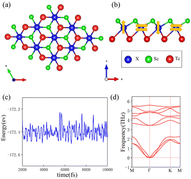
The crystal structure of ML-XSeTe is shown in Fig. 1(a). The atoms in the central layer form a triangular lattice with C6v symmetry, and after sandwiched by two atomic layers of different chalcogen atoms represented by light-green (Se) and dark-red (Te) balls, the overall symmetry reduces to C3v. The asymmetry between the top and bottom layers in ML-XSeTe breaks the inversion symmetry, thus allowing the DMI between the X ions. The optimized structural parameters of ML-XSeTe and the corresponding magnetic moments of X, Se, and Te atoms are listed in Table 1.
| a (A) | μ X (μB) | μ Se (μB) | μ Te (μB) | |
|---|---|---|---|---|
| NbSeTe | 3.62 | 0.75 | −0.026 | −0.071 |
| ReSeTe | 3.61 | 1.64 | −0.036 | −0.014 |
To investigate the magnetic properties of ML-XSeTe (X = Nb, Re), we adopt the following model Hamiltonian:
 | (1) |
The parameters of the magnetic anisotropic constant Ku, the DMI values, and the exchange interaction Aex are derived from the DFT calculations. The magnetic anisotropy energy is calculated as the energy difference between in-plane (IP) and out-of-plane (OP) magnetization. ReSeTe shows perpendicular magnetic anisotropy with the easy axis along the OP axis under 2% and 3% strain, while NbSeTe has an IP easy axis. The magnetic anisotropic constant Ku values of ReSeTe and NbSeTe are 7.1 × 10⁶ J m−3 and 2.72 × 10⁵ J m−3, respectively. The exchange stiffness A is an important parameter that controls the magnetization reversal of the magnetic materials. Based on the relationship between the micromagnetic free energy and the exchange energy, the exchange stiffness A is defined as44
 | (2) |
In this eqn (2), V is the volume of the unit cell and M is the unit magnetic vector. U is the exchange energy defined as the difference between the average total energy of noncollinear left-hand and right-hand spin spirals and the total energy of the collinear spin configuration. The exchange stiffness A values of the Janus ReSeTe and NbSeTe are 13.0 and 11.3 pJ m−1, respectively. The simulations are initialized with a single Néel skyrmion embedded in a ferromagnetic background. The FM spin arrangement is set as +z and the spin arrangement of the skyrmion core is set as −z. For the given initial conditions, the equilibrium magnetization configuration with minimum total energy is sought by successive iterations. The final magnetization state is reached until its total energy is converged.
We first discuss the DMI, which is the most interesting parameter for this work. According to Moriya's symmetry rules, since the reflection planes pass through the middle of the bonds between two adjacent Mn atoms, the DMI vector Dij for each pair of nearest-neighbor Cr atoms is perpendicular to their bonds. Thus, Dij can be expressed as
 | (3) |
 being the unit vector between sites i and j and ẑ indicating normal to the plane.16 The in-plane component d∥ along with the associated SOC energy ΔESOC can be evaluated by the chirality-dependent total energy difference approach with the two spin configurations depicted by yellow arrows in Fig. 1(b). Here we adopt the sign convention such that d∥ < 0 (d∥ > 0) favors spin canting with clockwise (counterclockwise) chirality. The contribution of d⊥ to the Néel skyrmion is negligible; hence we only evaluate the values of d∥. The DMI for one X atom from the nearest six magnetic X atoms is equal to ±(3/2)d∥ (the sign ± corresponds to left-hand and right-hand spin-spiral configurations, respectively). For a 4 × 1 × 1 supercell with four X atoms, the following relationship can be used45
 | (4) |
Hence, the in-plane component of the microscopic DMI is
 | (5) |
Subsequently, dij is converted into the micromagnetic DMI, D, with the expression45
 | (6) |
The calculated microscopic d∥ and micromagnetic D of the DMI for the Janus TMDs are shown in Fig. 2(b) and (c). There are significant values of d∥ and D for the Janus structures because the symmetry is broken by the difference OP elements.46 The values of d∥ for the Janus ML-NbSeTe and ML-ReSeTe are 1.78 and 4.82 meV, respectively. In order to ensure the energy convergence, the denser k-point meshes up to 6 × 24 × 1 are also tested (d∥ = 4.71 mev). The calculated results show that the 9 × 9 × 1 settings are enough to achieve the desired computation accuracy. The d⊥ of ML-NbSeTe and ML-ReSeTe is a tiny negative value. The extracted D values for the Janus NbSeTe and ReSeTe are 3.4 and 9.2 mJ m−2, respectively. The D for ML-NbSeTe and ML-ReSeTe is compared with that of Ir/Fe/Co/Pt and the graphene/Co interface. It is instructive to evaluate the associated SOC energy source to elucidate the origin of the DMI, which is defined as the difference in SOC energies extracted from opposite chirality in the ML Janus structure. The atomic resolved localization of the associated SOC energy ΔESOC is depicted in Fig. 5. Importantly, it is clearly shown that the large DMI for NbSeTe and ReSeTe mainly originates from the Te atom rather than from the TM atom and other chalcogen atoms.
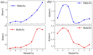 | ||
| Fig. 2 (a) The nearest-neighboring exchange coupling J and (b) in-plane DMI component d∥ as functions of strain in Janus ML-XSeTe. | ||
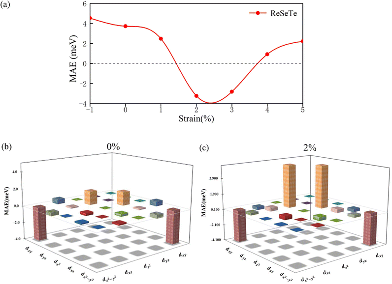
Now, we focus on the magnetic interaction parameters including J, K, and d∥ and their change under strain. The nearest-exchange coupling of ML-NbSeTe (ReSeTe) is FM (AFM) and when the tensile strain increases from 0% to 5%, the magnitude of this FM coupling can be effectively enhanced from 4.39 to 10.04 meV, while AFM coupling is from −15.15 to −19.14 meV. K of XSeTe is determined as a function of strain. One can see that pristine ReSeTe has IP magnetic anisotropy (IMA) of 3.721 meV, and NbSeTe has IMA of 1.14 meV. Interestingly, when under 2% and 3% tensile strain, the PMA of ReSeTe is 3.24 and 2.22 meV. We find that ML-XSeTe have a sizable DMI as shown in Fig. 2(b). Particularly, the d∥ of pristine ML-ReSeTe reaches 4.82 meV, which is comparable to state-of-the-art FM/HM HTSs, such as Pt/Co (∼3.0 meV)47 and Fe/Ir(111) (∼1.7 meV),48 thin films that have been demonstrated to be able to host chiral spin textures. One can also see that the tensile strain reduces the magnitude of d∥ of both ML-NbSeTe and ML-ReSeTe. The FM coupling and IMA are obviously increased and decreased, respectively, in Janus structures, which is more beneficial for the formation of long-range magnetic order.
In the following discussion, we choose ML-ReSeTe as an example to show in detail how tensile strain enhances the FM coupling. Schematic diagrams of Re–Se/Re–Te superexchange and Re–Re direct exchange couplings in Janus ReSeTe are shown in Fig. 3(a). Fig. 3(b) shows the bond lengths of Re–Re, Re–Te, and Re–Se. Since the bonding angle of Re–Se/Te–Re is close to 90°, according to the Goodenough–Kanamori–Anderson rules,49–52 the indirect exchange coupling between two nearest neighboring Re cations through intervening Se/Te anions is FM. In contrast, the direct exchange coupling between two nearest-neighboring Re cations is AFM. The competition between indirect FM and direct AFM couplings decides the final magnetic arrangement of Re atoms. When tensile strain is applied, the Re–Te and Re–Se distances hardly change, whereas the Re–Re distance obviously increases. Therefore, compared with indirect FM coupling, the direct AFM coupling decreases more strongly, which results in an effective decrease of J.53
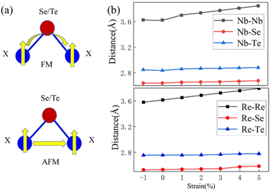 | ||
| Fig. 3 (a) Schematic diagrams of X–Se/Te–X superexchange and X–X direct exchange couplings in Janus ML-XSeTe. (b) Bond lengths of X–X, X–Te, and X–Se as functions of strain. | ||
From the atom-resolved magnetic anisotropy energy (MAE) of the ML-ReSeTe [Fig. 4(a)], one can see that the MAE underwent a transition from IP to OP and back to in-plane under strain. To further elucidate the mechanisms of the MAE change of Re atoms, we perform a comparative analysis of the MAE from orbital hybridization between the ML-ReSeTe under 0 and 2% tensile strain as shown in Fig. 4(b) and (c). For Re in pristine ReSeTe, the hybridization between dxy and dx2−y2 gives rise to IMA; however, the hybridization between dyz and dz2 constitutes PMA. The small magnitude of anisotropy of Re in pristine ReSeTe arises from the competition of these two hybridizations. When the strain is applied on the ReSeTe, the PMA contribution from the dxy and dx2−y2 hybridization significantly increases, which results in the giant PMA enhancement of the ML-ReSeTe. Furthermore, we investigate the origin of the change of the MAE arising from 5d orbital hybridization of the Te atom. According to the second-order perturbation theory,54,55 the MAE can be expressed as
For investigating the exceptional DMI in ML-XSeTe, we calculate the SOC energy difference ΔESOC of opposite chirality as shown in Fig. 5. One can see that the dominant contribution to the DMI stems from the adjacent Se and Te atoms. This behavior is similar to the DMI in FM/HM HTSs, where the SOC energy source comes from 5d transition metals in the interfacial layer. This is the so-called Fert-Levy type of DMI.31,53 In ML-XSeTe, when polarized electrons transfer between X atoms through Se/Te atoms, the spin orientations of these electrons can be tilted due to the spin–orbit scattering. Under tensile strain, the Te contribution to the DMI of CW chirality obviously decreases, which is responsible for the reduction of total DMI magnitude.
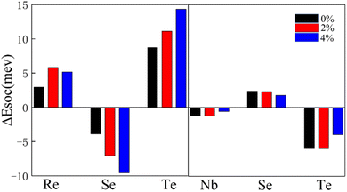 | ||
| Fig. 5 Atom-resolved localization of the SOC energy difference ΔESOC in Janus ML-XSeTe. Black, red, and blue bars represent ΔESOC of ML-XSeTe under 0%, 2%, and 4% tensile strain, respectively. | ||
Once magnetic interaction parameters of spin Hamiltonian are determined by first-principles calculation, we perform OOMMF simulations to explore the spin textures of Janus ML-XSeTe. We notice that the DMI/exchange coupling ratio |d∥/J| of ML-ReSeTe under 2% strain is about 0.24, which is larger than the typical range of 0.1–0.2 for the formation of skyrmions.56 Therefore, it is possible to realize chiral spin textures in ML-ReSeTe. We thus consider ML-ReSeTe in the following discussions.
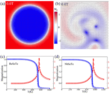
To further verify the aforementioned scenario, micromagnetic simulations based on the magnetic parameters extracted from DFT are performed for the ReSeTe and NbSeTe cases. The magnetization is initialized as a skyrmion like state and the relaxed states under zero magnetic field are depicted (Fig. 6(a)). One can see that a stable Néel skyrmion with the magnetization of the center along the −z direction, opposite to that of the FM background at the boundary, is observed in ML ReSeTe (Fig. 6(a)). It is found that the relaxed state for NbSeTe is not a skyrmion but a domain wall as shown in Fig. 6(b). As discussed in the previous paragraph, Néel skyrmions cannot be stabilized in NbSeTe because of its sizeable IP magnetic anisotropy, Ku (see in Table 2). Fig. 6(c) and (d) present the diagram of simulated magnetization via temperature. We find that the ML-NbSeTe and ML-ReSeTe have a high TC of 1023 K and 689 K.
| J (meV) | A (pJ m−1) | |Ku| (J m−3) | |
|---|---|---|---|
| NbSeTe | 9.42 | 11.29 | 2.72 × 10⁵ |
| ReSeTe | −15.35 | 13.04 | 7.1 × 10⁶ |
| u− | o+ | o− | ||||||||
|---|---|---|---|---|---|---|---|---|---|---|
| dxy | dyz | dz2 | dxz | dx2−y2 | dxy | dyz | dz2 | dxz | dx2−y2 | |
| dxy | 0 | 0 | 0 | −1 | 4 | 0 | 0 | 0 | 1 | −4 |
| dyz | 0 | 0 | −3 | 1 | −1 | 0 | 0 | 3 | −1 | 1 |
| dz2 | 0 | −3 | 0 | 0 | 0 | 0 | 3 | 0 | 0 | 0 |
| dxz | −1 | 1 | 0 | 0 | 0 | 1 | −1 | 0 | 0 | 0 |
| dx2−y2 | 4 | −1 | 0 | 0 | 0 | −4 | 1 | 0 | 0 | 0 |
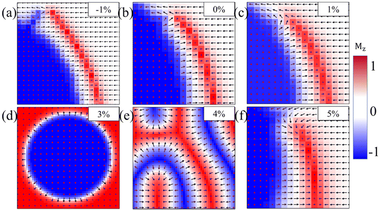
Furthermore, the impact of the external magnetic field on the size and shape of skyrmions in ML ReSeTe is also explored. The skyrmions at different external magnetic field strengths are mapped in Fig. 7. When the positive external magnetic field is applied, the rim of the skyrmion shrinks rapidly to its center with the increasing magnetic field. The size of the skyrmion decreases with the increasing positive external magnetic field. The significant decrease of the spin component opposite to the magnetic field induces a qualitative change of the skyrmion shape under an external magnetic field. Moreover, the rim of the skyrmion expands slowly outward with the increasing of the magnetic field, when the negative external magnetic field is applied. The size of the skyrmion increases with the increasing negative external magnetic field. Until the magnetic field is up to −0.5 T, the external magnetic field destroys the skyrmion state and finally turns into a collinear FM state with all the spin along the negative direction. The stability of the skyrmion against an external field is very high and the skyrmion can be stabilized under a large range of magnetic fields. When the external magnetic field is applied, the subtle balance of all involved energies is broken and subsequently reconstructed. The Zeeman energy introduces an external force, which makes the whole system tend to the FM state, while the DMI competes with the Zeeman energy and stabilizes the skyrmion against collapse to the FM state. In addition, the MAE of ReSeTe under 2% and 3% strain is PMA, so that strain can also affect the generation of skyrmions. We also provided the phase diagram of spin configurations under different tensile and compress strains for ReSeTe in Fig. 8. In addition to the strain and applied magnetic field, the electric field can also be used to regulate skyrmions. The experiment also found that skyrmions can be eliminated by controlling the direction of the current pulse by using an edge notch. Finally, the integrated electrical control of magnetic skyrmion generation and erasing and driving motion can be realized in a device structural unit, demonstrating the writing, erasing and addressing functions of the original device.57
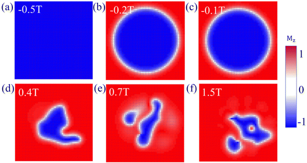 | ||
| Fig. 7 (a)–(f) The evolution of the size and shape of skyrmion as a function of the external magnetic field for ReSeTe. | ||
In summary, we have investigated the noncollinear magnetic properties of a family of Janus vdW magnets, ReSeTe and NbSeTe. All of which are FM metals with the Zener double-exchange interaction. A significant intrinsic DMI was found in ReSeTe and NbSeTe with the inversion asymmetry and strong SOC originated from the Te atoms. The micromagnetic simulations demonstrated that the Néel skyrmion could be stabilized in ML ReSeTe in the absence of an external magnetic field. The diameters of skyrmions in ML ReSeTe are 25 nm, which could be shrunk to sub 10 nm by an external magnetic field. The Néel skyrmion exists under a large range of external magnetic fields. In this work, we reveal the underlying physics of the existence of magnetic skyrmions in atomic layered materials. These findings provide an alternative platform to discover/design an intrinsic DMI and skyrmion in 2D vdW magnets for spin orbitronic and memory devices.
Data availability
The data that support the findings of this study are available from the corresponding author upon reasonable request.Conflicts of interest
There are no conflicts to declare.Acknowledgements
This work was supported by the Taishan Scholar Program of Shandong Province (Grant No. ts20190939), the Independent Cultivation Program of Innovation Team of Jinan City (Grant No. 2021GXRC043), and the National Natural Science Foundation of China (Grant Nos. 12004137 and 52173283).References
- A. Thiaville, S. Rohart, É. Jué, V. Cros and A. Fert, EPL, 2012, 100(5), 2611–2625 CrossRef.
- K. S. Ryu, L. Thomas, S. H. Yang and S. Parkin, Nat. Nanotechnol., 2013, 8, 527 CrossRef CAS PubMed.
- M. Bode, M. Heide, K. Von Bergmann, P. Ferriani, S. Heinze, G. Bihlmayer, A. Kubetzka, O. Pietzsch, S. Blügel and R. Wiesendanger, Nature, 2007, 447, 190 CrossRef CAS PubMed.
- S. Miwa, S. Ishibashi, H. Tomita, T. Nozaki, E. Tamura, K. Ando, N. Mizuochi, T. Saruya, H. Kubota, K. Yakushiji, T. Taniguchi, H. Imamura, A. Fukushima, S. Yuasa and Y. Suzuki, Nat. Mater., 2014, 13, 50 CrossRef CAS PubMed.
- V. G. Bar'yakhtar, A. N. Bogdanov and D. A. Yablonskí, Uspekhi Fizicheskih Nauk, 1988, 156(9), 47 CrossRef.
- W. Münzer, A. Neubauer, T. Adams, S. Mühlbauer, C. Franz, F. Jonietz, R. Georgii, P. Böni, B. Pedersen, M. Schmidt, A. Rosch and C. Pfleiderer, Phys. Rev. B: Condens. Matter Mater. Phys., 2010, 81, 1 CrossRef.
- X. Z. Yu, N. Kanazawa, Y. Onose, K. Kimoto, W. Z. Zhang, S. Ishiwata, Y. Matsui and Y. Tokura, Nat. Mater., 2011, 10, 106 CrossRef CAS PubMed.
- V. Dvořák, Phys. Status Solidi, 1971, 46, 763 CrossRef.
- T. Moriya, Phys. Rev., 1960, 120, 91 CrossRef CAS.
- V. E. Dmitrienko, E. N. Ovchinnikova, S. P. Collins, G. Nisbet, G. Beutier, Y. O. Kvashnin, V. V. Mazurenko, A. I. Lichtenstein and M. I. Katsnelson, Nat. Phys., 2014, 10, 202 Search PubMed.
- G. Beutier, S. P. Collins, O. V. Dimitrova, V. E. Dmitrienko, M. I. Katsnelson, Y. O. Kvashnin, A. I. Lichtenstein, V. V. Mazurenko, A. G. A. Nisbet, E. N. Ovchinnikova and D. Pincini, Phys. Rev. Lett., 2017, 119, 1 CrossRef PubMed.
- J. Miyawaki, S. Suga, H. Fujiwara, M. Urasaki, H. Ikeno, H. Niwa, H. Kiuchi and Y. Harada, Phys. Rev. B, 2017, 96, 1 CrossRef.
- J. Cho, N. H. Kim, S. Lee, J. S. Kim, R. Lavrijsen, A. Solignac, Y. Yin, D. S. Han, N. J. J. Van Hoof, H. J. M. Swagten, B. Koopmans and C. Y. You, Nat. Commun., 2015, 6, 1 Search PubMed.
- X. Ma, G. Yu, C. Tang, X. Li, C. He, J. Shi, K. L. Wang and X. Li, Phys. Rev. Lett., 2018, 120, 157204 CrossRef CAS PubMed.
- C. Moreau-Luchaire, C. Moutafis, N. Reyren, J. Sampaio, C. A. F. Vaz, N. Van Horne, K. Bouzehouane, K. Garcia, C. Deranlot, P. Warnicke, P. Wohlhüter, J. M. George, M. Weigand, J. Raabe, V. Cros and A. Fert, Nat. Nanotechnol., 2016, 11, 444 CrossRef CAS PubMed.
- A. Soumyanarayanan, M. Raju, A. L. G. Oyarce, A. K. C. Tan, M. Y. Im, A. P. Petrovic, P. Ho, K. H. Khoo, M. Tran, C. K. Gan, F. Ernult and C. Panagopoulos, Nat. Mater., 2017, 16, 898 CrossRef CAS PubMed.
- F. Liu, L. You, K. L. Seyler, X. Li, P. Yu, J. Lin, X. Wang, J. Zhou, H. Wang, H. He, S. T. Pantelides, W. Zhou, P. Sharma, X. Xu, P. M. Ajayan, J. Wang and Z. Liu, Nat. Commun., 2016, 7, 1 Search PubMed.
- H. Yang, O. Boulle, V. Cros, A. Fert and M. Chshiev, Sci. Rep., 2018, 8, 1 Search PubMed.
- C. Gong, L. Li, Z. Li, H. Ji, A. Stern, Y. Xia, T. Cao, W. Bao, C. Wang, Y. Wang, Z. Q. Qiu, R. J. Cava, S. G. Louie, J. Xia and X. Zhang, Nature, 2017, 546, 265 CrossRef CAS PubMed.
- H. Sun, S. S. Li, W. X. Ji and C. W. Zhang, Phys. Rev. B, 2022, 105, 195112 CrossRef CAS.
- M. H. Zhang, C. W. Zhang, P. J. Wang and S. S. Li, Nanoscale, 2018, 10, 20226 RSC.
- S. J. Zhang, C. W. Zhang, S. F. Zhang, W. X. Ji, P. Li, P. J. Wang, S. S. Li and S. S. Yan, Phys. Rev. B: Condens. Matter Mater. Phys., 2017, 96, 205433 CrossRef.
- G. Cheng and Z. Xiang, Science, 2019, 363(6428), eaav4450 CrossRef PubMed.
- T. Song, X. Cai, M. W. Y. Tu, X. Zhang, B. Huang, N. P. Wilson, K. L. Seyler, L. Zhu, T. Taniguchi, K. Watanabe, M. A. McGuire, D. H. Cobden, D. Xiao, W. Yao and X. Xu, Science, 2018, 360, 1214 CrossRef CAS PubMed.
- W. Xing, L. Qiu, X. Wang, Y. Yao, Y. Ma, R. Cai, S. Jia, X. C. Xie and W. Han, Phys. Rev. X, 2019, 9, 11026 CAS.
- X. Wang, J. Tang, X. Xia, C. He, J. Zhang, Y. Liu, C. Wan, C. Fang, C. Guo, W. Yang, Y. Guang, X. Zhang, H. Xu, J. Wei, M. Liao, X. Lu, J. Feng, X. Li, Y. Peng, H. Wei, R. Yang, D. Shi, X. Zhang, Z. Han, Z. Zhang, G. Zhang, G. Yu and X. Han, Sci. Adv., 2019, 5, 1 Search PubMed.
- S. Ikeda, K. Miura, H. Yamamoto, K. Mizunuma, H. D. Gan, M. Endo, S. Kanai, J. Hayakawa, F. Matsukura and H. Ohno, Nat. Mater., 2010, 9, 721 CrossRef CAS PubMed.
- B. Dieny and M. Chshiev, Rev. Mod. Phys., 2017, 89(2), 025008 CrossRef.
- F. Katmis, V. Lauter, F. S. Nogueira, B. A. Assaf, M. E. Jamer, P. Wei, B. Satpati, J. W. Freeland, I. Eremin, D. Heiman, P. Jarillo-Herrero and J. S. Moodera, Nature, 2016, 533, 513 CrossRef CAS PubMed.
- C. Huang, J. Feng, F. Wu, D. Ahmed, B. Huang, H. Xiang, K. Deng and E. Kan, J. Am. Chem. Soc., 2018, 140, 11519 CrossRef CAS PubMed.
- H. Yang, A. D. Vu, A. Hallal, N. Rougemaille, J. Coraux, G. Chen, A. K. Schmid and M. Chshiev, Nano Lett., 2016, 16, 145 CrossRef CAS PubMed.
- J. X. Yu and J. Zang, Sci. Adv., 2018, 4, 1 CAS.
- J. Liang, W. Wang, H. Du, A. Hallal, K. Garcia, M. Chshiev, A. Fert and H. Yang, Phys. Rev. B, 2020, 101, 1 Search PubMed.
- C. Xu, J. Feng, S. Prokhorenko, Y. Nahas, H. Xiang and L. Bellaiche, Phys. Rev. B, 2020, 101, 60404 CrossRef CAS.
- J. Yuan, Y. Yang, Y. Cai, Y. Wu, Y. Chen, X. Yan and L. Shen, Phys. Rev. B, 2020, 101, 094420 CrossRef CAS.
- Q. R. Cui, J. H. Liang, Z. J. Shao, P. Cui and H. X. Yang, Phys. Rev. B, 2020, 102, 094425 CrossRef CAS.
- Y.-J. Song, Q.-H. Zhang, X. Shen, X.-D. Ni, Y. Yao and R.-C. Yu, Chin. Phys. Lett., 2014, 31, 017501 CrossRef.
- H. Yang, J. Liang and Q. Cui, Nat. Rev. Phys., 2023, 5, 43–61 CrossRef.
- A. Fert, N. Reyren and V. Cros, Nat. Rev. Mater., 2017, 2, 17031 CrossRef CAS.
- D. Maccariello, W. Legrand, N. Reyren, K. Garcia, K. Bouzehouane, S. Collin, V. Cros and A. Fert, Nat. Nanotechnol., 2018, 13, 233 CrossRef CAS PubMed.
- N. Nagaosa and Y. Tokura, Nat. Nanotechnol., 2013, 8, 899 CrossRef CAS PubMed.
- D. Yan, S. Wang, Y. Lin, G. Wang, Y. Zeng, M. Boubeche, Y. He, J. Ma, Y. Wang, D. X. Yao and H. Luo, J. Phys.: Condens. Matter, 2020, 32, 1 Search PubMed.
- X. Yang, A. Banerjee and R. Ahuja, ChemCatChem, 2020, 12, 6013 CrossRef CAS.
- J. Sampaio, V. Cros, S. Rohart, A. Thiaville and A. Fert, Nat. Nanotechnol., 2013, 8, 839 CrossRef CAS PubMed.
- H. Yang, A. Thiaville, S. Rohart, A. Fert, H. Yang, A. Thiaville, S. Rohart, A. Fert and M. Chshiev, Phys. Rev. Lett., 2015, 115, 267210 CrossRef PubMed.
- J. Yuan, Y. Yang, Y. Cai, Y. Wu, Y. Chen, X. Yan and L. Shen, Phys. Rev. B, 2020, 101, 1 Search PubMed.
- O. Boulle, J. Vogel, H. Yang, S. Pizzini, D. de Souza Chaves, A. Locatelli, T. O. Menteş, A. Sala, L. D. Buda Prejbeanu, O. Klein, M. Belmeguenai, Y. Roussigné, A. Stashkevich, S. M Chérif, L. Aballe, M. Foerster, M. Chshiev, S. Auffret, I. M. Miron and G. Gaudin, Nat. Nanotechnol., 2016, 11, 449 CrossRef CAS PubMed.
- B. Dupé, M. Hoffmann, C. Paillard and S. Heinze, Nat. Commun., 2014, 5, 1 Search PubMed.
- J. Kanamori and J. Phys, Chem. Solids, 1959, 10, 87 CrossRef CAS.
- J. B. Goodenough, Phys. Rev., 1955, 100, 564 CrossRef CAS.
- P. W. Anderson, Career Theor. Physics, A, 2nd edn, 2005, vol. 115, p. 100 Search PubMed.
- H. Y. Lv, W. J. Lu, D. F. Shao, Y. Liu and Y. P. Sun, Phys. Rev. B: Condens. Matter Mater. Phys., 2015, 92, 11 CrossRef.
- D. S. Wang, R. Wu and A. J. Freeman, Phys. Rev. B: Condens. Matter Mater. Phys., 1993, 47, 14932 CrossRef CAS PubMed.
- B. S. Yang, J. Zhang, L. N. Jiang, W. Z. Chen, P. Tang, X. G. Zhang, Y. Yan and X. F. Han, Phys. Rev. B, 2017, 95, 1 Search PubMed.
- A. Fert and P. M. Levy, Phys. Rev. Lett., 1980, 44, 1538 CrossRef CAS.
- A. Fert, V. Cros and J. Sampaio, Nat. Nanotechnol., 2013, 8, 152 CrossRef CAS PubMed.
- W. Wang, D. Song and W. Wei, et al. , Nat. Commun., 2022, 13, 1593 CrossRef CAS PubMed.
| This journal is © The Royal Society of Chemistry 2023 |

