Structural, electronic, and electrocatalytic evaluation of spinel transition metal sulfide supported reduced graphene oxide†
Ramasamy
Santhosh Kumar
a,
Shanmugam
Ramakrishnan
a,
Sampath
Prabhakaran
 b,
Ae Rhan
Kim
ac,
Dharman Ranjith
Kumar
d,
Do Hwan
Kim
 ae and
Dong Jin
Yoo
 *ac
*ac
aDepartment of Energy Storage/Conversion Engineering (BK21 FOUR) of Graduate School, Hydrogen and Fuel Cell Research Center, Jeonbuk National University, Jeonju, Jeollabuk-do 54896, Republic of Korea. E-mail: djyoo@jbnu.ac.kr; Fax: +82-(0) 63-270-3909; Tel: +82-(0) 63-270-3608
bDepartment of Nano Convergence Engineering, Jeonbuk National University, Jeonju, 54896 Jeonbuk, Republic of Korea
cDepartment of Life Science, Jeonbuk National University, Jeonju, Jeollobuk-do 54896, Republic of Korea
dSchool of Mechanical Engineering, Kyungpook National University, Daegu, 702-701, Republic of Korea
eDivision of Science Education, Jeonbuk National University, Jeonju, 54896 Jeonbuk, Republic of Korea
First published on 25th December 2021
Abstract
Development of highly active and durable non-precious spinel transition metal sulfide (STMS)-based electrocatalysts plays a vital role in increasing the efficiency of hydrogen production via water electrolysis. Herein, we have synthesized a hierarchical nanostructured ZnCo2S4 on reduced graphene oxide (ZCS@rGO) sheet using a cost-effective hydrothermal synthesis method. The prepared ZCS@rGO shows improved hydrogen desorption and adsorption energy of the electrocatalyst surface towards efficient hydrogen evolution reaction (HER). As a result, ZCS@rGO showed lower HER overpotential (η10 = 135 eV) and Tafel slope (47 mV dec−1) and superior durability at 10 mA cm−2 for 36 h, as compared to the benchmark catalyst of Pt–C. Further, the electronic structure and HER mechanism of the ZCS@rGO catalyst were investigated by density functional theory calculations. This work provides a new pathway for the rational design of highly active and durable non-precious STMS-based electrocatalysts for hydrogen production.
1. Introduction
With rising concerns in population, energy demands, climate change, and shortages in fossil fuel resources, researchers are in need to explore efficient green and renewable energy systems.1,2 Hydrogen is one of the promising green fuels in next generation green vehicles due to its high gravimetric energy density and zero carbon emission.3,4 The hydrogen evolution reaction (HER) is the cathode-cell reaction in the water electrolysis device. Developing an active electrocatalyst to minimize the HER overpotential becomes a critical task for improving the hydrogen production from water electrolysis.5Precious metal catalysts of Pt/C and Pt-based alloys provide high HER efficiency, but their commercialization is highly restricted due to their scarcity, high price, sluggish reaction kinetics, and insufficient durability.6–8 Therefore, it is vital to design and fabricate non-precious and low cost catalysts that are highly electroactive and durable for the hydrogen economy.9 In this regard, incredible effort has been expended to explore various non-precious metal catalysts such as transition metals,10–12 metal sulfides,13–16 phosphides,6,17,18 nitrides,19,20 and hydroxides.21,22 Therefore, non-precious metals have been required to increase the fundamental catalytic assets such as surface alteration and phase conversion, in addition to the construction of heterostructures23,24 as a strategy focused on regulating electron distribution to improve electrocatalytic activity.25,26
Recently, transition metal sulfides have been one of the highest potential electrocatalysts used in energy storage and conversion devices owing to earth abundance, low cost, eco-friendliness, and superior electrocatalytic properties. Furthermore, the HER activity of transition metal sulfides (TMS) has been extensively studied due to their highly active sites, distinctive structural features, adjustable electronic properties, electrocatalytic activity, and low cost.27,28 Chemical state and electronic structure of the TMS's can determine the strength of reactant adsorption, reaction kinetics, and active intermediate formation towards HER. In particular, metallic sulfides exhibit excellent electrocatalytic activity towards HER due to their better redox-active reaction properties.29 Nevertheless, many investigations have shown that metallic sulfides have lower electron conductivity and durability in energy conversion applications. In this context, the electron conductivity of metal sulfides could be improved by incorporating carbon nanofillers such as graphene oxide,30,31 carbon frameworks,32 and carbon nanofibers.33 Among the various carbon conducting fillers, graphene sheets provide superb electron conductivity, large surface area, and prevent agglomeration of metal sulfides.34,35
Among transition metal sulfides, cobalt-based binary or ternary sulfides such as CoS2, MnCo2S4/NF, CuCo2S4, NiCo2S4, and FeCoMoS@N-rGO, have demonstrated promising electrocatalytic performance in OER/HER. It is crucial to identify the actual electrocatalytic active sites of transition metal sulfides for HER due to the presence of various stoichiometric ratios of metal ions with different oxidation states. Furthermore, the catalytic performance of an electrocatalyst could be drastically improved by tuning the morphology of the nanostructure, which can alter the electronic configuration and improve the active sites and area of the electrocatalyst. Based on the above inspiration, the fabrication of cobalt metal sulfides tailored with zinc components could be a promising new electrocatalyst for HER.36
In this work, we have grown hierarchical nanostructures of ZnCo2S4 (ZCS) on reduced graphene oxide (rGO) sheet using a cost-effective hydrothermal reaction. The hierarchical nanostructure growth of ZnCo2S4 on rGO (ZCS@rGO) provided excellent electron conductivity, extended surface area with more metal sulfide active sites, and improved the synergistic effect between metal sulfides and rGO for HER. The optimized electrocatalyst of ZCS@rGO shows lower HER overpotential (η10 = 135 eV), Tafel slope (47 mV dec−1), and superior durability at 10 mA cm−2 for 36 h as compared to the prepared Co3S4@rGO (CS@rGO) catalyst. Further, we investigated the density of states (DOS) and HER mechanism of ZCS@rGO catalyst by density functional theory (DFT) calculations. Notably, the ZCS@rGO catalyst coated carbon cloth electrode exhibits excellent H2 molecule evolution with a Faraday efficiency of about 93.74%. This present work provides a new pathway to the rational design of spinal TMS and rGO based electrocatalysts for efficient HER.
2. Methods
2.1 Chemicals
Graphite powder (Sigma Aldrich, 99.99% trace metals), zinc nitrate(II) hexahydrate (Yakuri Pure Chemicals, 95%), cobalt nitrate(II) hexahydrate (Alfa Aesar, 97.7%), urea (Alfa Aesar, 99.0–100.5%), sodium sulfide nonahydrate (Alfa Aesar, 98.0%), hydrazine monohydrate (Alfa Aesar, 98+%), ammonium fluoride (Sigma Aldrich, ≥98.0%), benchmark 20 wt% Pt/C (Alfa Aesar), 5% Nafion solution (Sigma-Aldrich), methanol, and potassium hydroxide were obtained from Samchun Pure Chemicals Co., South Korea.2.2 Synthetic procedure
Furthermore, the comparison material of the CS@rGO catalyst was prepared under identical synthesis conditions without adding zinc precursors in the hydrothermal process. The detailed synthesis procedure of CS@rGO is given in ESI.†
| Na2S → 2Na+ + S2− | (1) |
| Zn2+ + Co2+ + S2− → ZnCoS | (2) |
2.3 Characterization techniques
Morphological examination of the obtained materials was performed by field emission scanning electron microscopy (FE-SEM; SUPRA 40 VP; Carl Zeiss, Germany) and high-resolution transmission electron microscopy (HR-TEM; JEM-2010, JEOL) at the Center for University Wide Research Facilities (CURF) at Jeonbuk National University (JBNU), South Korea. The crystalline nature of materials was investigated using X-ray diffraction (XRD) copper Kα radiation (λ = 0.154 nm), Rigaku Corporation, Japan, and energy dispersive X-ray spectroscopy (EDS; Carl Zeiss, Germany, SUPRA 40 VP). The loading contents of Zn, Co, and S were evaluated by ICP-OES (inductively coupled plasma-optical emission spectrometry) with the iCAP 7000 series (Thermo Fisher Scientific) and the defective nature of materials was revealed by Raman spectroscopy (RAM-HR equipped with a 532 nm HORIBA-Lab helium–neon laser) at CURF, JBNU, Republic of Korea. Then, the binding nature and elemental composition of materials were examined with an X-ray photoelectron spectrometer (XPS; Axis-Nova, Kratos Inc.), and the surface area of the prepared catalyst was investigated using a Brunauer–Emmett–Teller (BET) Autosorb-iQ 2ST/MP physisorption analyzer at the Jeonju Center of the Korea Basic Science Institute (KBSI), Republic of Korea. The R-XAS based extended X-ray absorption fine structure (EXAFS) and X-ray absorption near edge structure (XANES) measurements at the Zn and Co K-edges were performed at the Sc-detector of Chonnam National University (model R-XAS, Rigaku, Japan) with total electron yield detection.2.4 Electrochemical characterization
The prepared electrocatalyst (∼3 mg) was disseminated in 1 mL of DI water and ethanol (1![[thin space (1/6-em)]](https://www.rsc.org/images/entities/char_2009.gif) :
:![[thin space (1/6-em)]](https://www.rsc.org/images/entities/char_2009.gif) 1) mixture. Further, 50 μL of 5% Nafion was added and sonicated for 60 min to generate a homogenous ink. The prepared ink was coated on carbon cloth (CC) (coated area 1 × 1 cm2) and dried at 60 °C overnight in a vacuum oven. For comparative study, commercial 20% Pt–C catalyst ink was prepared using a similar procedure.
1) mixture. Further, 50 μL of 5% Nafion was added and sonicated for 60 min to generate a homogenous ink. The prepared ink was coated on carbon cloth (CC) (coated area 1 × 1 cm2) and dried at 60 °C overnight in a vacuum oven. For comparative study, commercial 20% Pt–C catalyst ink was prepared using a similar procedure.
The HER electrochemical performance of prepared electrocatalysts was examined by a distinctive three-electrode system using CC supported catalyst as the working electrode, graphite rod (counter electrode), and saturated Ag/AgCl (reference electrode). The linear sweep voltammetry (LSV) curve was measured with 1 mV s−1 (scan rate) and 1.0 M KOH electrolyte. The double-layer capacitance value of the prepared catalyst was evaluated using CV curves with a different scan rate of 20 to 100 mV s−1 in the non-faradaic region. The slope of current densities vs. scan rate was double the value of double-layer capacitance (Cdl). Electrochemical impedance spectra (EIS) of prepared catalysts were measured using potentiostatic impedance with onset potential and a frequency range of 100 kHz to 0.1 Hz in 1.0 M KOH solution. The long-term stability test was measured by chronopotentiometry at a current density of 10 mA cm−2 for 36 h. All recorded potentials were converted into reversible hydrogen electrodes (RHE) using the following equation
| ERHE = EAgCl + (0.197 + 0.059 × pH) | (3) |
2.5 Computational analysis
The comprehensive density functional theory (DFT) calculation techniques are provided in the ESI.†3. Results and discussion
3.1 Structural and chemical evaluation of STMS
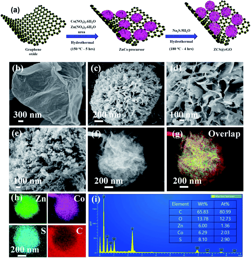
The ZnCo layered double hydroxide on the rGO (ZnCo LDH@rGO) was synthesized using metal precursors of cobalt nitrate(II) hexahydrate and zinc nitrate(II) hexahydrate in the presence of GO solution through a hydrothermal method at 150 °C for 5 h as presented in Fig. 1a. The GO has functional groups that generate strong interactions between the metal precursors and the GO sheet. During the hydrothermal reaction, the absorbed metal precursor was uniformly grown as a hierarchical structured ZnCo LDH on rGO, and simultaneously, GO was converted to rGO due to the presence of urea. Here, ammonium fluoride was used as the structure tuning agent to control the formation of hierarchical ZnCo LDH@rGO.36 Therefore, FE-SEM images of ZnCo LDH@rGO display the sphere-like hierarchical structure of ZnCo LDH grown on the rGO sheet, as shown in Fig. 1b–d.The ZnCo LDH@rGO was successfully converted to zinc cobalt sulfide on rGO (ZCS@rGO) via hydrothermal reaction at 180 °C for 4 h with sodium sulfide as the sulfur source and hydrazine monohydrate as the reducing agent. Fig. 1e shows the agglomerated nanoparticles covered on hierarchical sphere-like structure of ZCS@rGO, which confirms the conversion of ZnCo LDH@rGO to ZCS@rGO during the hydrothermal method.
This hierarchical sphere-like structure of ZCS along with the larger surface area of rGO favors the electron/ion transport with facile absorption of electrolyte during HER activity.15 Elemental mapping images of SEM-EDS show the structure of ZCS on the rGO sheet and confirm the presence of C, Zn, Co, and S (Fig. 1f–i).
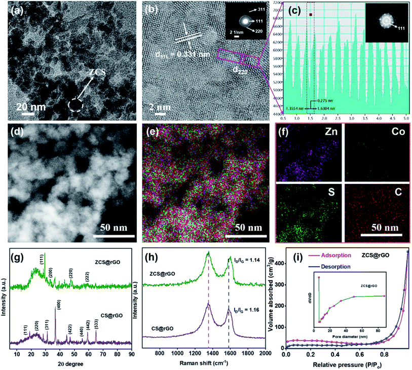
Moreover, the intrinsic morphology of the ZCS@rGO catalyst was analyzed by HR-TEM and STEM-HAADF as presented in Fig. 2a–f. The image shows that the lattice fringe distances of 0.33 and 0.27 nm belong to (111) and (220) planes of ZCS@rGO catalyst, respectively, which is in good agreement with the X-ray diffraction results (see Fig. 2g and S1†). The SAED pattern (Fig. 2b (inset image)) shows a ring with a bright spot revealing the polycrystalline nature of ZCS@rGO, which further confirms the (111), (220), and (311) planes. Additionally, Fast Fourier Transform (FFT) images also confirm the good crystalline nature of the ZCS@rGO catalyst (inset image of Fig. 2c). Subsequently, the EDS spectrum (Fig. 2d–f) of ZCS@rGO catalyst reflects the uniform distribution of Zn, Co, and S which confirms the formation of ZCS on the rGO sheet; Fig. S2† shows the EDX spectrum of ZCS@rGO catalyst and elemental composition of the ZCS@rGO catalyst are given in inset image of Fig. S2.† Fig. S3a–c† illustrates the TEM images of cobalt sulfides, which confirm the nanostructures were homogeneously grown on the rGO sheet. The HR-TEM image of Fig. S3b† confirms the lattice distances of CS@rGO to be 0.56 and 0.26 nm, corresponding to the (111) and (200) planes of CS@rGO catalyst, respectively. Furthermore, FFT images confirm the good crystalline nature of the CS@rGO catalyst. Additionally, STEM-HAADF and EDX spectra confirm the presence of Co and S elements on the rGO sheet (Fig. S3d–g†).
The crystalline states of ZCS@rGO and CS@rGO catalysts were examined by XRD, as presented in Fig. 2g. The XRD pattern displays characteristic CS@rGO catalyst peaks of 18.7°, 31.2°, 36.7°, and 55.5° belonging to the (111), (311), (400), and (440) planes, respectively. These peaks are reliably a typical diffraction pattern for CS@rGO (cubic structure) (JCPDS – 073-1073). The XRD patterns of ZCS@rGO catalyst exhibited strong peaks at 29.4°, 47.5°, and 59.1° belonging to the (111), (220), and (222) planes of the cubic ZCS (JCPDS – 047-1656), in agreement with previous literature reports.41 Notably, a broad peak appeared at ∼23.10°, which is related to the (002) plane of rGO in ZCS@rGO catalyst, which confirmed that GO was effectively transformed to rGO through the hydrothermal process.
Raman spectroscopy is a vital tool to investigate the defective and graphitic environment of ZCS@rGO and CS@rGO catalysts. Raman spectra of ZCS@rGO and CS@rGO catalysts, as revealed in Fig. 2h, showed distinctive peaks of the D band appearing in 1349 cm−1 ascribed to a defect nature of graphitic carbon, and G band appearing at 1580 cm−1 is associated with the sp2 nature of carbon atoms in the catalyst. The intensity ratio of D and G bands (ID/IG) values of CS@rGO catalyst were approximately 1.16, which was slightly higher than that of the ZCS@rGO catalyst (ID/IG = 1.14), which represents a good interaction between the ZCS and rGO and the successful formation of ZCS@rGO catalyst.42,43
The surface area and pore size of the ZCS@rGO catalyst were examined using a Brunauer–Emmett–Teller (BET) surface area analyzer, and the results are shown in Fig. 2i. ZCS@rGO catalyst displays a large specific surface area value of approximately 156 m2 g−1, which is comparatively greater than that of a recently reported ZnCoS based nanocomposite.44 The hysteresis curve (type IV isotherm) of ZCS@rGO catalyst displayed mesoporous features on a relative pressure of 0.4–1.0. The pore size distribution of the ZCS@rGO catalyst was further examined by a Barret–Joyner–Halenda model (BJH) study, and the curve is shown in the inset image of Fig. 2i. ZCS@rGO catalyst possesses a pore size around ∼18.1 nm, which confirms the mesoporous environment. Such a high specific surface area with mesoporous ZCS@rGO catalyst benefits an improved electrocatalytic activity towards HER. The weight percentages of Zn and Co in ZCS@rGO and CS@rGO catalysts were calculated by ICP-OES, indicating loadings of Zn and Co of 2.41% and 5.48%, respectively (Fig. S4†).
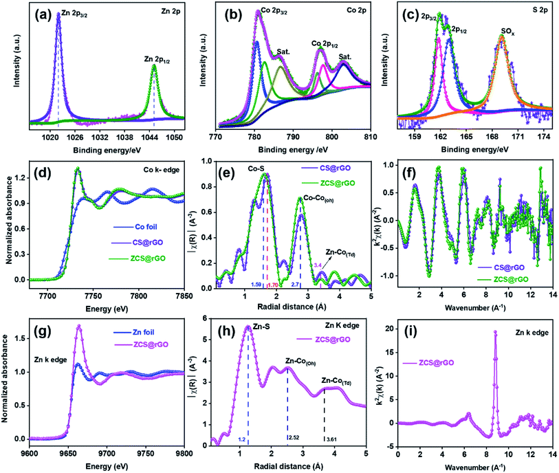
The chemical state of the ZCS@rGO catalyst was studied by XPS analysis. XPS survey spectra of ZCS@rGO showed the presence of Zn 2p, Co 2p, and S 2p peaks in Fig. 3a–c, which ensure the presence of Zn, Co, and S. The XPS spectra of Zn 2p reveal peaks at 1020.8 and 1045.9 eV belonging to Zn 2p3/2 and Zn 2p1/2, respectively,44 demonstrating the existence of Zn2+ in ZCS@rGO catalyst (Fig. 3a). The XPS spectra of Co 2p presented in Fig. 3b display peaks at 797.0 and 781.3 eV corresponding to Co 2p1/2 and Co 2p3/2, respectively.45 Additionally, the satellite (sat.) peaks appear at 786.4 and 802.9 eV, which indicates the existence of Co(III) and Co(II).46,47 The XPS spectra of S 2p (Fig. 3c) at 161.4 and 162.8 eV corresponds to S 2p3/2 and S 2p1/2, respectively.48,49 The peak positions at 163.8 and 168.4 eV are representative peaks of metal sulfide bonds (S2−) and SO42−/HSO4−, respectively. Further, Fig. S5† depicts the survey spectrum, O 1s, C 1s, and atomic percentage, which clearly shows the peak binding energy and composition of the ZCS@rGO catalyst.
To identify the in-depth elemental positions and electronic configuration of the optimal electrocatalyst, ZCS@rGO was examined by X-ray absorption spectroscopy (XAS) analysis with reference foils such as Zn and Co. The XANES spectra characterize the coordination environment of ZCS@rGO and CS@rGO catalysts,50 as shown in Fig. 3. The XANES spectra disclose a characteristic peak at 7710 eV due to Co 4sp – Co 3d hybridization,51 which further confirms the state of Co in CS@rGO and ZCS@rGO catalysts. Further, Fig. 3d shows the main absorption peaks of ZCS@rGO and CS@rGO catalysts appearing at 7730 eV due to electron transition from the occupied orbital of Co 1s to unoccupied orbitals of Co 4p. Interestingly, the peak intensities of ZCS@rGO catalyst are slightly increased as compared to Co-foil and CS@rGO catalyst due to the presence of Zn atoms. This confirms the oxidation states of cobalt are +2 and +3 in ZCS@rGO catalyst.52
EXAFS spectra evaluate the coordination environment of cationic and anionic metal ions in CS@rGO and ZCS@rGO catalysts, as presented in Fig. 3e. The spectra show a strong peak around 1.59 Å, ascribed to the Co–S bonds in ZCS@rGO catalyst, whereas the Co–S peak position of CS@rGO catalyst was shifted to 1.70 Å because of Zn atoms occupying the Td site in the spinel structure. Further, peaks around 2.7 and 3.4 Å correspond to Co–Co(Oh) and Zn–Co(Td) in octahedron and tetrahedron sites, respectively.53 In Fig. 3f, oscillations of the Co K-edge show a neat EXAFS spectra from a good signal to noise percentage of CS@rGO and ZCS@rGO catalysts.54Fig. 3g shows Zn K-edge spectra of the XANES spectrum for Zn foil and ZCS@rGO catalyst, which confirms the coordination environment of zinc atoms (Zn2+), in which pre-edge and post-edge peaks appear at 9638 eV and 9664 eV, respectively. Further, the EXAFS spectrum confirms the presence of the Zn–S bond, Zn–Co(Oh) octahedron species, and Zn–Co(Td) tetrahedron species, with corresponding peaks appearing at 1.2, 2.52, and 3.61 Å for ZCS@rGO catalyst, as observed in Fig. 3h. Fig. 3i displays the oscillation frequency of ZCS@rGO catalyst, with the EXAFS spectra collected with a good signal to noise ratio in the Zn K-edge.55
The bond distance of the transition metal sulfide was decreased by increasing the central metal ion redox state because of the decreased effective ionic radius.56 The promising electrocatalytic activity performance was based on the mixed oxidation state of Co2+ and Co3+ cationic valences existing in the octahedron site of ZCS@rGO. From the XAS results, the Zn electronegativity was low (Pauling electronegativity is 1.65) compared with Co (Pauling electronegativity is 1.88), indicating that the sulfide atom has a tendency to gain an electron from Co, confirming S–Zn–S–Co–S structures in ZCS. Fig. S6† shows the spin and structure state change of Co ion from CS@rGO to ZCS@rGO catalysts. For the electron transition, Co atoms exhibit different electron configurations of t52g e2g (high spin, Co2+) and t62g e0g (low spin, Co3+) with a stable configuration of Zn2+ (t62g e4g).57
The high spin Co2+ (t52g e2g) and low spin Co3+ (t62g e0g) are changed in the occupied state when adding Zn atoms. Therefore, the CFSE energy level variance of Co2+ is less than that of Co3+ in CS@rGO and ZCS@rGO catalysts, and the CFSE energy value of Zn2+ ion is about zero as a stable state of ZCS@rGO catalyst. Based on CFSE calculations, it is important to describe Jahn–Teller (JT) effects,58 which are important in describing the catalytic properties. Therefore, tetragonal distortion is present in the asymmetry electron of Co2+ state (low spin) as shown in Fig. S7, S8, and Table S1.† Improving the electrochemical performance of STMS requires suppressing the effects of Jahn–Teller distortion. Lan et al. observed that suppression of the Jahn–Teller distortion in In-doping MnCo2O4 enhanced the HER actives.59,60 We observed strong electronic interaction between Zn/Co and S in the ZCS@rGO catalyst, which can significantly minimize the Jahn–Teller distortion of Co2+ cation in ZCS@rGO, thus leading to improved intrinsic conductivity and electron transfer between metal cations and sulfur. Additionally, the ZCS@rGO catalyst offers enhanced HER activity with fast kinetics and better deprotonation/protonation reaction processes.
3.2 Electrocatalytic evaluation of STMS
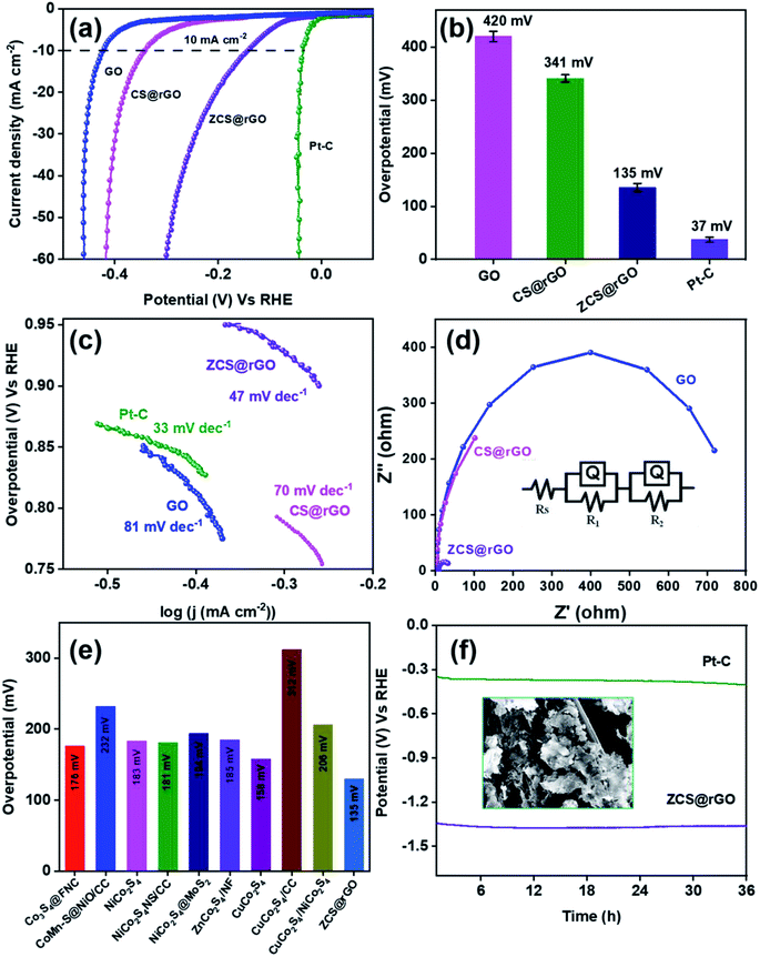
The HER activity of the as-prepared electrocatalyst was analyzed using electrochemical techniques of cyclic voltammetry (CV), linear sweep voltammetry (LSV), and chronopotentiometry with 1.0 M KOH solution. Approximately 3 mg of prepared electrocatalyst was coated on cleaned CC, which acts as the working electrode. Fig. 4a shows iR corrected LSV comparative curves of ZCS@rGO/CC, CS@rGO/CC, GO/CC, and 20% Pt/C catalysts, and Fig. S9† displays LSV curves of CC and GO/CC. Notably, the optimal ZCS@rGO/CC exhibits a lower overpotential of 135 mV at 10 mA cm−2 as related to CS@rGO/CC (341 mV) and GO/CC (420 mV) at the same current density, which is higher than the benchmark catalyst of 20% Pt–C (37 mV) as presented in Fig. 4b.The reaction kinetics of ZCS@rGO/CC, CS@rGO/CC, GO/CC, and Pt–C/CC catalysts were evaluated using the Tafel slope, which is derived from the slope of overpotential vs. log(j) plot. As presented in Fig. 4c, the ZCS@rGO/CC catalyst has a smaller Tafel slope value of 47 mV dec−1 when compared to CS@rGO/CC (70 mV dec−1) and GO/CC (81 mV dec−1) catalysts, which is higher than the benchmark catalyst of 20% Pt–C (33 mV dec−1) catalyst. This result demonstrates that the optimal ZCS@rGO/CC has improved inherent catalytic activity with enhanced HER kinetics. The Tafel results reveal the HER reactions follow the following rate-determining steps.
| H2O + C + e− → C − Had + OH−: Volmer step (120 mV dec−1) | (4) |
| H2O + C − Had + e− → H2 + C + OH−: Heyrovsky step (40 mV dec−1) | (5) |
| C − Had + C − Had → H2 + 2C: Tafel step (30 mV dec−1) | (6) |
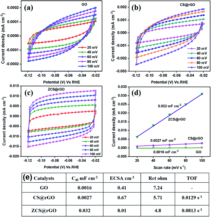
In the first step, hydrogen is adsorbed onto the ZCS@rGO (C – representing ZCS@rGO catalyst in steps 4–6) surface and generates hydroxide ions. H2 gas molecules escape from the ZCS@rGO catalyst surface through two distinct reaction paths: (i) the Heyrovsky reaction and (ii) the Tafel reaction, as given in eqn (5) and (6), respectively. According to the above reaction pathway, H2 molecules are out from the ZCS@rGO catalyst surface via the Volmer–Heyrovsky step. The electrochemical impedance spectra (EIS) of ZCS@rGO/CC, CS@rGO/CC, and GO/CC catalysts were measured using the onset potential of HER and frequency ranging between 100 KHz to 0.1 Hz in 1.0 M KOH, as shown in Fig. 4d. The results show that the ZCS@rGO catalyst has a lower Rct value of 4.8 Ω when compared to CS@rGO/CC (5.71 Ω) and GO/CC (7.24 Ω) catalysts, indicating that ZCS@rGO/CC catalyst has good conductivity and excellent electron-transport kinetics for HER. Furthermore, ZCS@rGO/CC catalyst indicates a lower overpotential of 135 mV at a current density of 10 mA cm−2 as compared to recently disclosed non-precious metal electrocatalysts as shown in Table S3† and Fig. 4e. We estimated the electrochemically active surface area (ECSA) of ZCS@rGO/CC, CS@rGO/CC, and GO/CC catalysts by calculating the electrochemical double-layer capacitance (Cdl). The Cdl values were calculated by measuring CV curves with different scan rates in the non-faradaic region, as presented in Fig. 5a–d. The double-layer capacitance (Cdl) value of ZCS@rGO/CC was ∼0.032 mF cm−2, which is higher than those of CS@rGO (0.0027 mF cm−2) and GO (0.0016 mF cm−2) catalysts. The calculated ESCA value of ZCS@rGO/CC (8.01 cm−2) catalyst demonstrates the existence of a greater number of electroactive sites in ZCS@rGO. Furthermore, the ZCS@rGO/CC had a higher turnover frequency (TOF) value of 0.0813 s−1 at 302 mV, which is greater than that of the CS@rGO/CC (0.0129 s−1) catalyst, as shown in Fig. 5e. These results further confirm that the hierarchical structure of zinc cobalt sulfides on reduced graphene sheet provides more active sites for HER.61
The long-term durability of ZCS@rGO/CC catalyst was examined using chronopotentiometry at 10 mA cm−2 in alkaline 1.0 M KOH for 36 h. The results indicated that there were no significant changes in potential after 36 h, which confirms the high catalytic stability of the ZCS@rGO/CC catalyst (Fig. 4f). In contrast, the CS@rGO/CC catalyst exhibited a significant change in potential after 36 h, as shown in Fig. S10.†
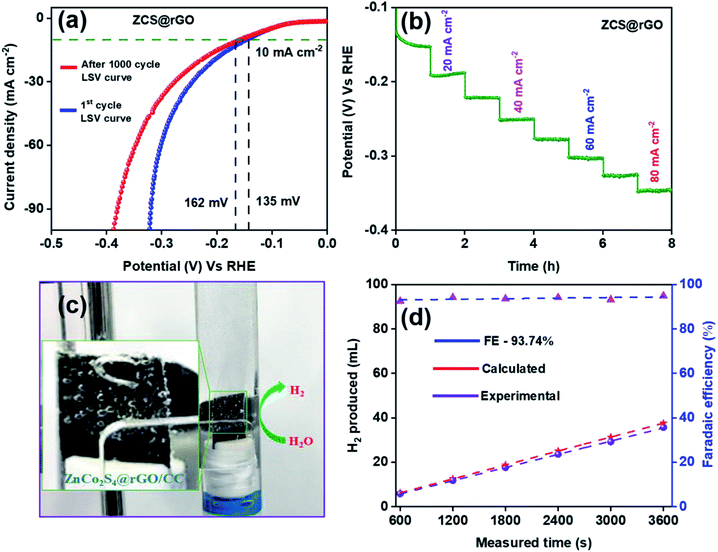
Fig. 6a shows LSV curves of ZCS@rGO/CC catalyst before and after 1000 cycles of CV in 1.0 M KOH solution (Fig. S11† (inset image of SEM)). The results indicated that there is a small difference in potential at a current density of 10 mA cm−2, showing the improved stability of the ZCS@rGO/CC catalyst for HER. The HER stability test for the optimum ZCS@rGO/CC catalyst was achieved through multi-step chronopotentiometry. Fig. 6b displays the multi-step chronopotentiometry curve of ZCS@rGO/CC catalyst recorded at different current densities from 10 to 80 mA cm−2 with a one-hour time interval for each step. The results display that initially the potential has a slight change at the current density of 10–20 mA cm−2, but there were no significant changes in potential at current densities of 30–80 mA cm−2 over 8 h. This result confirms the ZCS@rGO/CC catalyst has excellent mass transport properties and stability of electrode.52
After the durability test, we investigated the morphology changes and chemical states of ZCS@rGO/CC catalyst through FE-SEM, TEM, and XPS analyses. After the durability test, morphology changes of ZCS@rGO/CC catalyst were investigated through SEM and TEM analyses, as shown in Fig. S12 and S13.† Fig. S12† shows the SEM images of the ZCS@rGO/CC, and there is a change of sphere-like hierarchical structure after the durability test. SEM-EDAX elemental mapping (Fig. S12c and d†) of ZCS@rGO/CC confirms the existence of Zn, Co, S, and C in ZCS@rGO catalyst after durability test. Additionally, TEM images of the zinc cobalt sulfide supported carbon cloth show ZCS is agglomerated on rGO sheet and good crystallinity with a d-space value of 0.197 nm belonging to (220) planes of ZCS@rGO catalyst, as shown Fig. S13a.† Furthermore, HR-TEM-EDAX elemental mapping (Fig. S13d and e†) revealed the existence of Zn, Co, S, and C in ZCS@rGO catalyst after durability testing. After durability, the EDS spectra SEM (inset table in Fig. S12d†) and TEM of ZCS@rGO (inset table in Fig. S13e†) catalyst shows that zinc, cobalt, and sulfur contents were gradually reduced as compared to before durability test, which demonstrates the conversion of sulfide to sulfur oxides with a slight dissolution of the catalyst during the durability test.62 Furthermore, we investigated the chemical composition of ZCS@rGO catalyst by using XPS analysis after durability tests (Fig. S14†), which shows the intensity of Co 2p and Zn 2p peaks were reduced and the S 2p peaks confirmed the oxidation of sulfur during hydrogen evolution (see Fig. S14†). Additionally, the element composition (atomic %) of ZCS@rGO was gradually reduced after the durability test, as shown in the inset table of Fig. S14f.† This result confirms the adsorption of OH active spices on the surface of the ZCS@rGO catalyst.61 The efficiency of hydrogen evolution was measured by calculating the faradaic efficiency of the ZCS@rGO/CC catalyst through the water displacement method, as shown in Fig. 6c. Fig. 6d shows that the faradaic efficiency of H2 evolution by ZCS@rGO catalyst was 93.74%.
3.3 Computational methodology and results
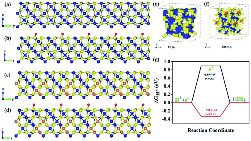
To get a better understanding of the catalytic performance of ZCS@rGO, DFT calculations were used to investigate the HER mechanism of Co3S4 and ZnCo2S4. The DFT calculation was performed by using the Vienna ab initio simulation package software (VASP). Initially, structural optimization was carried out in order to find the best catalyst structures, which are schematically represented in Fig. S18.† Fig. S15† shows the density of states (DOS) of CS and ZCS, and the results display the highest charge density near the Fermi level, demonstrating a large number of charge carriers. The DOS distribution of ZCS near the Fermi surface increases the electron transfer and good H* adsorption ability of sphere-like hierarchical ZCS in the prepared catalyst.63–65We investigated the Gibbs free energy value (ΔGH*) of ZnCo2S4 adsorbed with H atoms to describe the HER mechanism.66 Based on a previous report, we evaluated the detailed ΔGH values of ZnCo2S4 and Co3S4 to understand the HER catalytic activity. Stable configurations for the adsorption of H atoms on the spinel Co3S4 and ZnCo2S4 systems are shown in Fig. 7. As shown in Fig. 7a, b and S16,† the hydrogen atoms are adsorbed on the surface of the S atom of Co3S4 to form H*-Co3S4. The H2 adsorption occurs similarly in ZnCo2S4 to form H*-ZnCo2S4, as Fig. 7c, d, and S17† portray. Based on the DFT calculations, formation energy values are listed in Fig. S18 and Table S2,† and ΔGH values for H*-Co3S4 and H*-ZnCo2S4 were determined to be 0.894 eV and −0.329 eV for the adsorption of H atoms on S sites, respectively. Further, the optimized electronic structures are shown in Fig. 7e and f for Co3S4 and ZnCo2S4 electrocatalysts. Fig. 7g displays the calculated free energy values (ΔGH*) for hydrogen adsorption on ZnCo2S4 and Co3S4. In theoretical HER estimation, change in Gibbs free energy during hydrogen adsorption (ΔGH*) is considered as one of the crucial parameters. The electrocatalyst materials are expected to show excellent HER activity when the ΔGH* is close to 0 eV. Based on the DFT results, hydrogen atoms prefer to adsorb on the S atoms of Co3S4 and ZnCo2S4 layers. We observed that the excellent activity of the spinel ZnCo2S4 as compared to Co3S4 was mainly due to the fact that Zn atoms occupy Td sites and Co atoms occupy Oh sites. Therefore, it can be inferred that the transition metal sulfide system enhances H2 evolution behavior, as a result improving the catalytic efficiency for HER.
4. Conclusion
In summary, we have successfully grown hierarchical ZCS on rGO through a two-step hydrothermal method. The morphology, chemical and physical properties of ZCS@rGO catalyst were investigated using various analytical techniques, including SEM, TEM, XRD, XPS, XAS, and BET analyses, which support the formation of a hierarchical morphology of ZCS on rGO sheets. The key parameters of the hierarchical ZCS@rGO catalyst provided a large surface area with more exposed electrocatalytic active sites and improved the interfacial interactions between hierarchical ZCS and the rGO sheet. As a result, the hierarchical ZCS@rGO catalyst showed low overpotential (135 mV at 10 mA cm−2), Tafel slope value (47 mV dec−1), and outstanding durability as compared to CS@rGO catalyst in alkaline medium. Further, we evaluated the electronic structure and HER mechanism of ZCS using DFT calculations. Thus, the present work paves the way to the development of high surface area, hierarchical structured, bimetal sulfide-based electrocatalysts for green production of hydrogen gas via water electrolysis.Conflicts of interest
The authors declare no competing financial interest.Acknowledgements
This work was supported by Korea Institute of Energy Technology Evaluation and Planning (KETEP) grant funded by the Korea government (MOTIE) (No. 20214000000040, Innovation Research Center for Next Generation Battery based Materials, Parts and Applied Technology). This research was supported by Basic Science Research Program through the National Research Foundation of Korea (NRF) funded by the Ministry of Science, ICT and Future Planning (NRF-2020R1A2B5B01001458).References
- Z. W. Seh, J. Kibsgaard, C. F. Dickens, I. Chorkendorff, J. K. Norskov and T. F. Jaramillo, Science, 2017, 355, eaad4998 CrossRef PubMed.
- C. Wei, Y. Sun, G. G. Scherer, A. C. Fisher, M. Sherburne, J. W. Ager and Z. J. Xu, J. Am. Chem. Soc., 2020, 142, 7765–7775 CrossRef CAS PubMed.
- J. Zhu, L. Hu, P. Zhao, L. Y. S. Lee and K.-Y. Wong, Chem. Rev., 2020, 120, 851–918 CrossRef CAS PubMed.
- I. Ledezma-Yanez, W. D. Z. Wallace, P. Sebastian-Pascual, V. Climent, J. M. Feliu and M. T. M. Koper, Nat. Energy, 2017, 2, 17031 CrossRef CAS.
- C. Wei, R. R. Rao, J. Peng, B. Huang, I. E. L. Stephens, M. Risch, Z. J. Xu and Y. Shao-Horn, Adv. Mater., 2019, 31, 1806296 CrossRef PubMed.
- J. Kibsgaard, C. Tsai, K. Chan, J. D. Benck, J. K. Norskov, F. Abild-Pedersen and T. F. Jaramillo, Energy Environ. Sci., 2015, 8, 3022–3029 RSC.
- C. Hu, L. Zhang and J. Gong, Energy Environ. Sci., 2019, 12, 2620–2645 RSC.
- J. Zhang, Q. Zhang and X. Feng, Adv. Mater., 2019, 31, 1808167 CrossRef PubMed.
- N. Xue, Z. Lin, P. Li, P. Diao and Q. Zhang, ACS Appl. Mater. Interfaces, 2020, 12, 28288–28297 CrossRef CAS PubMed.
- J. Kim, H. Jung, S.-M. Jung, J. Hwang, D. Y. Kim, N. Lee, K.-S. Kim, H. Kwon, Y.-T. Kim, J. W. Han and J. K. Kim, J. Am. Chem. Soc., 2021, 143, 1399–1408 CrossRef CAS PubMed.
- Y. Liu, J. Zhang, B. Han, X. Wang, Z. Wang, C. Xue, G. Bian, D. Hu, R. Zhou, D.-S. Li, Z. Wang, Z. Ouyang, M. Li and T. Wu, J. Am. Chem. Soc., 2020, 142, 6649–6660 CrossRef CAS PubMed.
- M. Ferri, J. D. Elliott, M. F. Camellone, S. Fabris and S. Piccinin, ACS Catal., 2021, 11, 1897–1910 CrossRef CAS.
- X. Zhu, J. Dai, L. Li, D. Zhao, Z. Wu, Z. Tang, L.-J. Ma and S. Chen, Carbon, 2020, 160, 133–144 CrossRef CAS.
- J. Hu, Y. Ou, Y. Li, D. Gao, Y. Zhang and P. Xiao, ACS Sustainable Chem. Eng., 2018, 6, 11724–11733 CrossRef CAS.
- G. Song, Z. Wang, J. Sun, J. Sun, D. Yuan and L. Zhang, Electrochem. Commun., 2019, 105, 106487 CrossRef CAS.
- A. R. Puente Santiago, T. He, O. Eraso, M. A. Ahsan, A. N. Nair, V. S. N. Chava, T. Zheng, S. Pilla, O. Fernandez-Delgado, A. Du, S. T. Sreenivasan and L. Echegoyen, J. Am. Chem. Soc., 2020, 142, 17923–17927 CrossRef CAS PubMed.
- B. G. Fiss, N.-N. Vu, G. Douglas, T.-O. Do, T. Friscic and A. Moores, ACS Sustainable Chem. Eng., 2020, 8, 12014–12024 CrossRef CAS.
- U. P. Suryawanshi, U. V. Ghorpade, D. M. Lee, M. He, S. W. Shin, P. V. Kumar, J. S. Jang, H. R. Jung, M. P. Suryawanshi and J. H. Kim, Chem. Mater., 2021, 33, 234–245 CrossRef CAS.
- B. Cao, G. M. Veith, J. C. Neuefeind, R. R. Adzic and P. G. Khalifah, J. Am. Chem. Soc., 2013, 135, 19186–19192 CrossRef CAS PubMed.
- J. Li, C. Yao, X. Kong, Z. Li, M. Jiang, F. Zhang and X. Lei, ACS Sustainable Chem. Eng., 2019, 7, 13278–13285 CrossRef CAS.
- D. Rathore, M. D. Sharma, A. Sharma, M. Basu and S. Pande, Langmuir, 2020, 36, 14019–14030 CrossRef CAS PubMed.
- A. Karmakar, K. Karthick, S. Kumaravel, S. S. Sankar and S. Kundu, Inorg. Chem., 2021, 60, 2023–2036 CrossRef CAS PubMed.
- X. Du, J. Huang, J. Zhang, Y. Yan, C. Wu, Y. Hu, C. Yan, T. Lei, W. Chen, C. Fan and J. Xiong, Angew. Chem., Int. Ed., 2019, 58, 4484–4502 CrossRef CAS PubMed.
- M. E. G. Lyons, R. L. Doyle, D. Fernandez, I. J. Godwin, M. P. Browne and A. Rovetta, Electrochim. Acta, 2014, 45, 60–62 CAS.
- Y. Jiao, Y. Zheng, M. Jaroniec and S. Z. Qiao, Chem. Soc. Rev., 2015, 44, 2060–2086 RSC.
- Y. Wang, W. Qiu, E. Song, F. Gu, Z. Zheng, X. Zhao, Y. Zhao, J. Liu and W. Zhang, Natl. Sci. Rev., 2018, 5, 327–341 CrossRef CAS.
- D.-Y. Wang, M. Gong, H.-L. Chou, C.-J. Pan, H.-A. Chen, Y. Wu, M.-C. Lin, M. Guan, J. Yang, C.-W. Chen, Y.-L. Wang, B.-J. Hwang, C.-C. Chen and H. Dai, J. Am. Chem. Soc., 2015, 137, 1587–1592 CrossRef CAS PubMed.
- M. Wang, L. Zhang, Y. He and H. Zhu, J. Mater. Chem. A, 2021, 9, 5320–5363 RSC.
- X. Wu, X. Han, X. Ma, W. Zhang, Y. Deng, C. Zhong and W. Hu, ACS Appl. Mater. Interfaces, 2017, 9, 12574–12583 CrossRef CAS PubMed.
- S. Sahoo and J.-J. Shim, ACS Sustainable Chem. Eng., 2017, 5, 241–251 CrossRef CAS.
- X. Yang, H. Sun, P. Zan, L. Zhao and J. Lian, J. Mater. Chem. A, 2016, 4, 18857–18867 RSC.
- Z. Zhang, Y. Huang, X. Liu, C. Chen, Z. Xu and P. Liu, Carbon, 2020, 157, 244–254 CrossRef CAS.
- F. Luo, D. Ma, Y. Li, H. Mi, P. Zhang and S. Luo, Electrochim. Acta, 2019, 299, 173–181 CrossRef CAS.
- D. Strmcnik, P. P. Lopes, B. Genorio, V. R. Stamenkovic and N. M. Markovic, Nano Energy, 2016, 29, 29–36 CrossRef CAS.
- B. Hammer and J. K. Norskov, Adv. Catal., 2000, 45, 71–129 CAS.
- J. Gautam, Y. Liu, J. Gu, Z. Ma, J. Zha, B. Dahal, L.-N. Zhang, A. N. Chishti, L. Ni, G. Diao and Y. Wei, Adv. Funct. Mater., 2021, 2106147 CrossRef CAS.
- R. Santhosh Kumar, K. Govindan, S. Ramakrishnan, A. R. Kim, J.-S. Kim and D. J. Yoo, Appl. Surf. Sci., 2021, 556, 149765 CrossRef CAS.
- J. Yu, S. Chen, W. Hao and S. Zhang, ACS Nano, 2016, 10, 2500–2508 CrossRef CAS PubMed.
- V. Mani, S. Shanthi, T.-K. Peng, H.-Y. Lin, H. Ikeda, Y. Hayakawa, S. Ponnusamy, C. Muthamizhchelvan and S.-T. Huang, Sens. Actuators, B, 2019, 287, 124–130 CrossRef CAS.
- Z. Fang, L. Peng, Y. Qian, X. Zhang, Y. Xie, J. J. Cha and G. Yu, J. Am. Chem. Soc., 2018, 140, 5241–5247 CrossRef CAS PubMed.
- A. Pramanik, S. Maiti, T. Dhawa, M. Sreemany and S. Mahanty, Mater. Today Energy, 2018, 9, 416–427 CrossRef.
- N. Logeshwaran, S. Ramakrishnan, S. S. Chandrasekaran, M. Vinothkannan, A. R. Kim, S. Sengodan, D. B. Velusamy, P. Varadhan, J.-H. He and D. J. Yoo, Appl. Catal., B, 2021, 297, 120405 CrossRef CAS.
- S. Ramakrishnan, J. Balamurugan, M. Vinothkannan, A. R. Kim, S. Sengodan and D. J. Yoo, Appl. Catal., B, 2020, 279, 119381 CrossRef CAS.
- S. Dutta, C. Ray, Y. Negishi and T. Pal, ACS Appl. Mater. Interfaces, 2017, 9, 8134–8141 CrossRef CAS PubMed.
- M. Oku and K. Hirokawa, J. Electron Spectrosc. Relat. Phenom., 1976, 8, 475–481 CrossRef CAS.
- R. Z. Wang and Y. Zhang, Mol. Syst. Des. Eng., 2020, 5, 565–572 RSC.
- P. Shi, Y. Zhang, G. Zhang, X. Zhu, S. Wang and A.-L. Wang, J. Mater. Chem. A, 2021, 9(35), 19719–19724 RSC.
- A. Sivanantham, P. Ganesan and S. Shanmugam, Adv. Funct. Mater., 2016, 26, 4661–4672 CrossRef CAS.
- S. Ramakrishnan, M. Karuppannan, M. Vinothkannan, K. Ramachandran, O. J. Kwon and D. J. Yoo, ACS Appl. Mater. Interfaces, 2019, 11, 12504–12515 CrossRef CAS PubMed.
- D. Chen, C.-L. Dong, Y. Zou, D. Su, Y.-C. Huang, L. Tao, S. Dou, S. Shen and S. Wang, Nanoscale, 2017, 9, 11969–11975 RSC.
- M. Wang, C.-L. Dong, Y.-C. Huang and S. Shen, ACS Catal., 2020, 10, 1855–1864 CrossRef.
- Z. Dai, H. Geng, J. Wang, Y. Luo, B. Li, Y. Zong, J. Yang, Y. Guo, Y. Zheng, X. Wang and Q. Yan, ACS Nano, 2017, 11, 11031–11040 CrossRef CAS PubMed.
- W. Deeloed, Y. Hanlumyuang, W. Limphirat, S. Suramitr, K. Chansaenpak, P. Kanjanaboos, S. Wannapaiboon and W. Wattanathana, Crystals, 2021, 11(10), 1256 CrossRef CAS.
- L. Liu, D. K. Wang, P. Kappen, D. L. Martens, S. Smart and J. C. Diniz da Costa, Phys. Chem. Chem. Phys., 2015, 17, 19500–19506 RSC.
- Z. Zhao, G. Tian, V. Trouillet, L. Zhu, J. Zhu, A. Missiul, E. Welter and S. Dsoke, Inorg. Chem. Front., 2019, 6, 1861–1872 RSC.
- S. Chen, H. Huang, P. Jiang, K. Yang, J. Diao, S. Gong, S. Liu, M. Huang, H. Wang and Q. Chen, ACS Catal., 2020, 10, 1152–1160 CrossRef CAS.
- J. K. Burdett, G. D. Price and S. L. Price, J. Am. Chem. Soc., 1982, 104, 92–95 CrossRef CAS.
- M. D. Kaplan, J. Am. Chem. Soc., 2006, 128, 10631–10632 CrossRef CAS.
- B. Lan, Y. Xiang, X. Luo, D. Wu, L. Zhang, J. Duan, M. Guo, Y. Ito and Y. Liu, Chem. Eng. J., 2022, 430, 132886 CrossRef CAS.
- S. Hirai, S. Yagi, A. Seno, M. Fujioka, T. Ohno and T. Matsuda, RSC Adv., 2016, 6, 2019–2023 RSC.
- Y.-H. Fang and Z.-P. Liu, ACS Catal., 2014, 4, 4364–4376 CrossRef CAS.
- P. W. Menezes, A. Indra, A. Bergmann, P. Chernev, C. Walter, H. Dau, P. Strasser and M. Driess, J. Mater. Chem. A, 2016, 4, 10014–10022 RSC.
- G. Kresse and D. Joubert, Phys. Rev. B, 1999, 59, 1758–1775 CrossRef CAS.
- G. Kresse and J. Furthmuller, Comput. Mater. Sci., 1996, 6, 15–50 CrossRef CAS.
- D. Voiry, H. Yamaguchi, J. Li, R. Silva, D. C. Alves, T. Fujita, M. Chen, T. Asefa, V. B. Shenoy, G. Eda and M. Chhowalla, Nat. Mater., 2013, 12, 850–855 CrossRef CAS PubMed.
- D. Zhao, K. Sun, W.-C. Cheong, L. Zheng, C. Zhang, S. Liu, X. Cao, K. Wu, Y. Pan, Z. Zhuang, B. Hu, D. Wang, Q. Peng, C. Chen and Y. Li, Angew. Chem., Int. Ed., 2020, 59, 8982–8990 CrossRef CAS PubMed.
Footnote |
| † Electronic supplementary information (ESI) available. See DOI: 10.1039/d1ta08224h |
| This journal is © The Royal Society of Chemistry 2022 |

