 Open Access Article
Construction of honeycomb-like Te-doped NiCo-LDHs for aqueous supercapacitors and as oxygen evolution reaction electrocatalysts†
Ding
Zhang
 abc,
Xiaoning
Tang
d,
Zhaoguang
Yang
ab,
Ying
Yang
 *a and
Haipu
Li
 *ab
*ab
aCollege of Chemistry and Chemical Engineering, Central South University, Changsha 410083, P. R. China. E-mail: yangy@csu.edu.cn
bKey Laboratory of Hunan Province for Water Environment and Agriculture Product Safety, Changsha 410083, P. R. China. E-mail: lihaipu@csu.edu.cn
cSchool of Chemistry and Chemical Engineering, Hainan Normal University, Haikou Hainan 571158, P. R. China
dFaculty of Chemical Engineering, Kunming University of Science and Technology, Kunming Yunnan 650500, P. R. China
First published on 10th December 2021
Abstract
The design and fabrication of hierarchical porous transition metal (oxy)hydroxide electrodes with desired electrochemical activities are highly demanded in electrocatalysis and supercapacitors. Herein, assisted by the dynamic oxygen bubble template method (DOBT), the tuned fabrication of honeycomb-like Te-doped nickel-cobalt layered double hydroxides (HS-Te-NiCo-LDHs) by controlled anodic electrodeposition was reported. It was found that the Te dopant helped to stabilize the more electroactive α-phase of NiCo-LDHs and the DOBT was efficient in constructing the hierarchical porous structure of the monolithic electrode. In addition, density functional theory (DFT) was applied to reveal the internal factors of the enhanced oxygen evolution reaction (OER) and supercapacitor performance of HS-Te-NiCo-LDH. The well-designed HS-Te-NiCo-LDH/NiO/NF electrode gave an ultralow overpotential of 221 mV at 10 mA cm−2 as OER electrocatalyst with prolonged stability of over 24 hours (kept at ∼90 mA cm−2) and a high specific capacity of 650 C g−1 for aqueous supercapacitor in 1 mol L−1 KOH solution.
1. Introduction
Electrocatalysts and alternative energy storage devices have been extensively developed with an increase in demand for clean and sustainable energy. As the primary reaction, oxygen evolution plays a key role in many energy conversion technologies, such as regenerative fuel cells, solar water-splitting, and rechargeable metal–air batteries.1,2 However, the oxygen evolution reaction (OER) is kinetically sluggish with a large overpotential due to the four-electron redox processes. In order to achieve a quick and efficient generation of oxygen by electrochemical water oxidation, cost-effective, stable, and robust OER catalysts are highly desirable. Among them, iridium- and ruthenium-based oxides are the most widely recognized ones with satisfactory performances in activity and stability, but their industrial applications on a large scale are still limited by high costs and shortage of reserves.3,4It was discovered that the first-row transition metal (oxy)hydroxides, especially the nickel- and cobalt-based materials, exhibited superior electrocatalytic performances, and they seem to open the possibility for various applications by providing innovative electrode materials for those promising future energy devices that rely on electrochemical reaction processes,5 like lithium-oxygen batteries6 and water splitting for hydrogen production.7 Among them, the nickel-cobalt layer double hydroxide (NiCo-LDH) has been a hot research topic for its low cost, environmental friendliness, and high electrochemical activity.8 It is known that NiCo-LDH has α- and β-phases, where the β-phase is thermodynamically stable owing to a hexagonal close-packed structure of M2+ (M = Ni, Co) and OH− ions with an interlayer spacing of about 0.46 nm, while the α-phase consists of M(OH)2 (M = Ni, Co) interlayers with an interlayer spacing of 0.75–0.8 nm.9 Theoretically, the larger interlayer spacing would provide more space between the interlayers and thus accommodate more water molecules and anions by the intermolecular hydrogen-bond network, which is conducive to the rapid mass transportation or intercalation/de-intercalation of protons in electrochemical reactions. In this vein, the α-phase is more favorable than the β-phase.10,11 However, under the alkaline conditions, the pure α-NiCo-LDH is unstable and tends to transform into the β-phase.10,12
Many efforts have been devoted to solve the above challenging issue, such as doping Fe3+, Mn4+, and Ir4+ in the nickel and cobalt hydroxide lattices to form ternary LDHs.13–15 Upon introducing the above ions, the specific capacitance can be increased due to the contribution of the M3+/M2+ or M3+/M4+ (M = Fe, Mn, and Ir) redox reaction. However, the stability was not radically improved because α-LDH remains rather unstable, especially during the transformation of M3+/M2+ or M3+/M4+ in the electrochemical process.
Interestingly, chalcogens are found to be able to stabilize the α-NiCo-LDH configuration effectively.16 In recent years, metal chalcogenide composite materials17–19 such as Ni3Te2, Ni3S2 and Ni3Se2,20 CoTe2@CdTe and CoSe2@CdSe21 and CoTe222 have exhibited good pseudocapacitive and OER performance. Te ions, which are not electroactive and would not involve any change of valence during the electrochemical reaction process, have great potential for stabilizing the α-LDH structure.11,23,24 As known, tellurium has a higher theoretical volumetric capacity (ca. 2621 mA h cm−3), higher atomic radius (1.42 Å), lower electronegativity (2.1), higher conductivity (∼1000 S m−1), or higher covalent character, and it is expected that telluride would show a higher performance than other chalcogenides, by stabilizing the α-NiCo-LDH and increasing the electrocatalytic activity of the doped material.
For the efficient doping of metal or non-metal elements into heteromultimetallic hydroxides, electrochemical deposition has proven to be a rapid and practical method.25 Besides, electrode materials with macro/micro/mesoporous hierarchical structures are highly favorable for a superior electrochemical performance in view of the more active sites, shorter paths for charge transfer, and improved charge–discharge efficiency.26,27 On the one hand, the three-dimensional (3D) nickel foam (NF) can be used as the substrate to provide macropores, as well as a high specific surface area and electrical conductivity.25 On the other hand, for the generation of micro- or mesopores, the dynamic oxygen bubble template method (DOBT)28,29 was taken into account, which made use of anodic oxygen (O2) bubbles as gaseous templates via the controlled OER during the anodic electrodeposition process. Due to the sluggish four-electron transfer kinetics and large overpotential, the sizes of O2 bubbles by OER are tinier and the process is more controllable in contrast to the H2 bubble template technique occurring on the cathodic electrode.30–32 To facilely induce the OER process and facilitate the DOBT method, special attention was paid to the conditions of electrolytes and substrates. As is known, the high concentration carbonate and hydrocarbonate electrolytes were always used to help improve electrical conductivity, increase the alkalinity, and avoid the precipitation of metal ions.29,33 Besides, the NF substrate was intentionally pre-anodized before electrodeposition to produce a highly active porous nickel oxide layer (NiO) to reduce the overpotential of the OER34 and therefore facilitate the DOBT.
Herein, in this study, DOBT-directed Te-doped anodic electrodeposition was utilized to prepare the hierarchical porous HS-Te-NiCo-LDH/NiO/NF monolithic electrode, targeting the electrocatalyst toward the OER and supercapacitor. At the same time, the electrochemical behavior of the synthesized materials was discussed in-depth understanding by density functional theory (DFT).
2. Preparation and characterization
Before electrodeposition, the NF substrate (20 × 10 × 2 mm3) was sequentially ultrasonically cleaned by alcohol, acetone, trichloroethylene, and ultrapure water. Firstly, the NF substrate was anodized at 2 V (vs. Ag/AgCl) in an electrolyte containing fluorine (1 mol L−1 NH4F as corrosion and punching agent, 1 mol L−1 (NH4)2SO4, 15 mL glycol, 15 mL glycerol as a leveling agent and 70 mL ultrapure water) for 2 h. The anodic oxidation process can be demonstrated by eqn (S1) (ESI†).The high concentration carbonate solution (pH 10.7, 100 mL) containing Ni(NO3)2, Co(NO3)2, and TeO2 provided good electrical conductivity during the electroplating. The anodic electrodeposition process can be demonstrated by eqn (1) and (2).33,35
| M2+ + 3OH− → MOOH(s) + H2O + e− | (1a) |
| M(OH)2 (s) + OH− ⇌ MOOH(s) + H2O + e− | (1b) |
| NiO + OH− → NiOOH(s) + e− | (2a) |
| NiOOH(s) + 2OH− → NiOOH(s) + H2 + O2 + 2e− | (2b) |
The obtained potentials were normalized to a reversible hydrogen electrode (RHE) according to eqn (S2) (ESI†). Energy (E) and power (P) densities were calculated based on specific capacity by using the eqn (S3) and (S4) (ESI†).
The detailed preparation including single factor experiments (Fig. S1, ESI†) and testing procedures is displayed in the ESI.†
3. Results and discussion
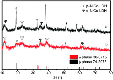
In order to explore the properties of the prepared electroactive materials, the deposited layers (HS-Te-NiCo-LDH and HS-NiCo-LDH) were ultrasonically detached from the anodized NF substrate (NiO/NF). The XRD characterization (Fig. 1) showed that the HS-NiCo-LDH sample exhibited mixed phases of α/β-NiCo-LDH (the content of the α- and β-phases is 31% and 69%, respectively),9,10 while the HS-Te-NiCo-LDH shows mainly the α-NiCo-LDH phase (content 93%) with a small amount of the β-NiCo-LDH phase (content 7%).36–38 The results indicated that the addition of Te could effectively stabilize the α-phase of the HS-Te-NiCo-LDH. The lattice parameter a (3.05 Å, = 2d110) of the α-phase HS-Te-NiCo-LDH, as evaluated by the Bragg formula, is found to be larger than that of the α-NiCo-LDH in the HS-NiCo-LDH sample (3.00 Å). This elongation may be caused by the larger ionic radius of lattice Te4+ (0.97 Å) when compared to Ni2+ (0.69 Å) and Co2+ (0.65 Å). Similarly, the interlayer spacing (d003) of the α-phase HS-Te-NiCo-LDH (7.62 Å) is also larger than that in the HS-NiCo-LDH sample (d003 = 7.44 Å). This may be due to the necessary compensation for the charge excess brought by Te4+ ions.39 As suggested by Song et al.,24 the doped Te prefers to be incorporated at the edge transition metal sites.The TEM images of the detached HS-Te-NiCo-LDH (Fig. 2a) presenting the overlapping of the sheet-like deposits, and the HRTEM images (Fig. 2b) display three different sets of lattice fringes, corresponding to (101), (015), and (006) of α-NiCo-LDH.10 The selected area electron diffraction (SAED) pattern (Fig. 2c) exhibited the polycrystalline rings of HS-Te-NiCo-LDH, indexed to (006), (015), (018), and (110) of α-NiCo-LDH.8,36 These findings were consistent with the XRD analysis. The fast Fourier transfer (FFT) pattern along the [006] zone axis also showed a lattice diffraction pattern with all the major diffraction spots indexed (Fig. 2d).
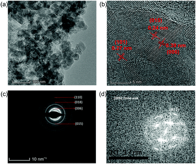 | ||
| Fig. 2 (a and b) TEM and HRTEM images of HS-Te-NiCo-LDH, (c) SAED pattern of the corresponding (b) image; and (d) corresponding FFT pattern aligned along the [006] zone axis. | ||
The composition of the detached HS-Te-NiCo-LDH coating was also examined using XPS (Fig. 3). The full XPS spectrum (Fig. 3a) confirmed the presence of Ni, Te, Co, and O elements. The Ni 2p XPS spectrum (Fig. 3b) displayed two spin–orbit peaks, Ni 2p3/2 (855.4 eV) and Ni 2p1/2 (873.6 eV), each accompanied by a satellite peak at high binding energy (at 862 and 881 eV, respectively), demonstrating the bivalent oxidation state in the 2p spin–orbit of Ni.40 The Te 3d spectrum (Fig. 3c) showed characteristic peaks at 576.1 and 586.2 eV, which can be assigned to Te 3d5/2 and Te 3d3/2, respectively. These characteristic peaks correspond well to tetravalent tellurium.41–43 As for the Co 2p XPS spectrum (Fig. 3d), the fitting results demonstrated the coexistence of Co3+ (780.8 eV) and Co2+ (783.7 eV) and the main ingredient was Co3+.44 As displayed in Fig. 3e, the deconvolution of the O 1s spectrum hinted at the presence of the adsorbed water (532.1 eV), hydroxide or oxyhydroxide group (–OOH or –OH, 531.2 eV), and lattice oxygen bonds (O–M, 529.6 eV),25,45 where –OH/–OOH groups were found to be the major oxygen component. According to the XPS analysis (Table S1, ESI†), the metal ratio of the detached HS-Te-NiCo-LDH deposit was Ni![[thin space (1/6-em)]](https://www.rsc.org/images/entities/char_2009.gif) :
:![[thin space (1/6-em)]](https://www.rsc.org/images/entities/char_2009.gif) Co
Co![[thin space (1/6-em)]](https://www.rsc.org/images/entities/char_2009.gif) :
:![[thin space (1/6-em)]](https://www.rsc.org/images/entities/char_2009.gif) Te = 1.37
Te = 1.37![[thin space (1/6-em)]](https://www.rsc.org/images/entities/char_2009.gif) :
:![[thin space (1/6-em)]](https://www.rsc.org/images/entities/char_2009.gif) 1
1![[thin space (1/6-em)]](https://www.rsc.org/images/entities/char_2009.gif) :
:![[thin space (1/6-em)]](https://www.rsc.org/images/entities/char_2009.gif) 0.01. By comparing the XPS results of HS-NiCo-LDH (Fig. S2, ESI†) and HS-Te-NiCo-LDH (Fig. 3), it was found that the doping of Te had almost no effect on the valence states of the Ni, Co, and O elements.
0.01. By comparing the XPS results of HS-NiCo-LDH (Fig. S2, ESI†) and HS-Te-NiCo-LDH (Fig. 3), it was found that the doping of Te had almost no effect on the valence states of the Ni, Co, and O elements.
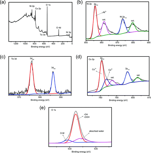 | ||
| Fig. 3 (a) XPS spectrum of the HS-Te-NiCo-LDH full spectrum, enlarged XPS spectra of (b) Ni 2p, (c) Te 3d, (d) Co 2p and (e) O 1s. | ||
Field-emission scanning electron microscopy (FE-SEM) analysis was implemented to identify the structural feature and morphology of the title electrode HS-Te-NiCo-LDH/NiO/NF (Fig. 4). The SEM analysis exhibited the obvious macroscopic 3D skeleton of the samples (Fig. S3, ESI†), the rougher surface of anodized NF substrate (Fig. 4b), and the honeycomb-like structure of the electrodeposit HS-Te-NiCo-LDH (Fig. 4c and d) (polarization potential interval 0.2–1.2 V, 5 mV s−1, 200 s). The hole diameter was ca. 40 nm (Fig. 4d) and the wall thickness was 8–10 nm. The sample without the NiO bottom layer (Te-NiCo-LDH/NF) showed a flocculent structure without porous features (Fig. S3d, ESI†). And the HS-NiCo-LDH/NiO/NF sample without the Te dopant gave a porous structure (Fig. S3e, ESI†). These observations suggest the significance of the presence of an active NiO layer for the construction of the hierarchical porous structure via DOBT.46
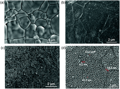 | ||
| Fig. 4 (a) SEM image of the bare NF, (b) anodized NF substrate for 2 h, (c) HS-Te-NiCo-LDH/NiO/NF, and (d) enlarged SEM image of HS-Te-NiCo-LDH/NiO/NF. | ||
EDS and detailed elemental mapping of the HS-Te-NiCo-LDH/NiO/NF electrode (Fig. S4, ESI†) confirmed the existence of Te, Co, and Ni elements as well as their homogeneous distribution on the 3D NiO/NF substrate. The metal ratio is determined as Ni![[thin space (1/6-em)]](https://www.rsc.org/images/entities/char_2009.gif) :
:![[thin space (1/6-em)]](https://www.rsc.org/images/entities/char_2009.gif) Co
Co![[thin space (1/6-em)]](https://www.rsc.org/images/entities/char_2009.gif) :
:![[thin space (1/6-em)]](https://www.rsc.org/images/entities/char_2009.gif) Te = 1.3
Te = 1.3![[thin space (1/6-em)]](https://www.rsc.org/images/entities/char_2009.gif) :
:![[thin space (1/6-em)]](https://www.rsc.org/images/entities/char_2009.gif) 1
1![[thin space (1/6-em)]](https://www.rsc.org/images/entities/char_2009.gif) :
:![[thin space (1/6-em)]](https://www.rsc.org/images/entities/char_2009.gif) 0.013 (Fig. S4, ESI†), greatly close to that by XPS.
0.013 (Fig. S4, ESI†), greatly close to that by XPS.
The OER performance of the HS-Te-NiCo-LDH/NiO/NF electrode and parallel samples (HS-NiCo-LDH/NiO/NF, Te-NiOH/NiO/NF, and Te-CoOH/NiO/NF) were investigated in both 0.1 mol L−1 and 1 mol L−1 KOH solutions (Fig. 5). As seen in Fig. S5 (ESI†), the NiO/NF substrate was obviously more active than NF in view of the OER performance. This demonstrated that the nickel oxide active layer obtained by anodic oxidation can induce the OER reaction for the DOBT-directed electrodeposition to be more likely. The electrical conductivity of different samples was evaluated by electrochemical impedance spectroscopy (EIS) characterization studies (Fig. S6 and Table S2, ESI†). According to the fitting results, the HS-Te-NiCo-LDH/NiO/NF electrode presents the lowest series resistance (Rs) of 0.55 Ω among the four electrodes for its higher electrochemical conductivity. In addition, the HS-Te-NiCo-LDH/NiO/NF electrode also shows a smaller charge-transfer resistance (Rct) of 1.13 Ω than others, indicating a fast charge transfer process. The lower Rs and Rct may be related to the honeycomb-like structure and ultra-thin hole wall (∼10 nm) of the HS-Te-NiCo-LDH/NiO/NF, which provided more electroactive sites and short electron conduction pathways.47
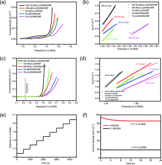
The LSV curves measured in 0.1 mol L−1 KOH electrolyte at 5 mV s−1 are shown in Fig. 5a. The overpotentials of HS-Te-NiCo-LDH/NiO/NF, HS-NiCo-LDH/NiO/NF, Te-NiCo-LDH/NF, Te-NiOH/NiO/NF, and Te-CoOH/NiO/NF at 10 mA cm−2 were 231, 258, 260, 314, and 388 mV, respectively. The HS-Te-NiCo-LDH/NiO/NF electrode gave a lower overpotential and faster increase of current density, possibly also owing to higher electrical conductivity and more exposed electrochemical active sites brought by a honeycomb-like structure.39,48 Typically, the characteristic peaks near 1.2–1.3 V (Fig. 5a) were related to reactions M2+(OH)2 → M3+OOH and M3+OOH → M4+O2 (M = Ni, Co),9 by which these in situ formed M3+/4+ species are believed to promote the formation and de-protonation of the intermediate species (OOH) as well as the O2 evolution, so as to enhance the OER performance.9 The computed Tafel slopes of HS-Te-NiCo-LDH/NiO/NF in 0.1 mol L−1 KOH electrolyte (Fig. 5b) was as low as 56 mV dec−1. The small Tafel slope indicated the fast electron and mass transfer between the electrode and electrolyte.49
The LSV curves measured in 1 mol L−1 KOH electrolyte are shown in Fig. 5c. At 10 mA cm−2, the overpotentials of HS-Te-NiCo-LDH/NiO/NF, Te-NiCo-LDH/NF, HS-NiCo-LDH/NiO/NF, Te-NiOH/NiO/NF, Te-CoOH/NiO/NF, and bare NF were 221, 247, 251, 270, 279, and 321 mV, respectively. Given the fairly low overpotential (221 mV) at 10 mA cm−2, the HS-Te-NiCo-LDH/NiO/NF sample could be a more efficient OER catalyst when compared with those reported transition-metal water-oxidation catalysts including Ex-FeN-MC,50 Co/MnO@GC-700,51 or MoS252 (Table S3, ESI†). In addition, it required as low as 229 and 267 mV to reach 20 and 100 mA cm−2, respectively (Table S4, ESI†). The lower Tafel slope of HS-Te-NiCo-LDH/NiO/NF (< 60 mV dec−1) was a reflection of high electron transfer efficiency.49
The multi-step chronopotentiometric curve of the HS-Te-NiCo-LDH/NiO/NF electrode was measured in 1 mol L−1 KOH solution from 60 to 540 mA cm−2 at a rate of 60 mA cm−2 per 500 s (Fig. 5e). The steady stride (about 0.05 V) was indicative of excellent conductivity, mechanical robustness, and transport properties. The chronoamperometry curves in 1 mol L−1 and 0.1 mol L−1 KOH electrolytes were recorded at the respective constant potential (Fig. 5f), where the HS-Te-NiCo-LDH/NiO/NF electrode reached a current density of ∼90 mA cm−2 at 1.71 V in 1 mol L−1 KOH solution, and ∼18 mA cm−2 at 1.73 V in 0.1 mol L−1 KOH solution. The current density in both cases remained stable even in 24 h runs.
The structure of the HS-Te-NiCo-LDH after 24 h runs was investigated in Fig. S7a (ESI†). The SEM images demonstrated that the surface becomes slightly rough, caused by a mild corrosion. The corresponding EDS results showed lower content of Co and Te (16.97% and 0.27% now vs. 17.95% and 0.3% before), suggesting a weak dissolution during the stability test. The XRD patterns of HS-Te-NiCo-LDH and HS-NiCo-LDH after 24 h runs were compared (Fig. S7c, ESI†). As for HS-Te-NiCo-LDH, the α-phase is dominant, possibly as a result of Te doping to effectively prevent the transformation from the α-phase to the β-phase. The HS-NiCo-LDH sample was still an α/β-mixture with the β-phase dominating. The OER performances of HS-Te-NiCo-LDH/NiO/NF, Te-NiCo-LDH/NF, and HS-NiCo-LDH/NiO/NF electrodes after 24 h runs were also tested in 1 mol L−1 KOH solutions, resulting in overpotentials of 230, 245, and 254 mV at 10 mA cm−2 with the corresponding Tafel slopes of 46, 65, 59 mV dec−1, respectively (Fig. S8, ESI†). Among them, the HS-Te-NiCo-LDH/NiO/NF still showed the best OER performance. The above results demonstrated that the doping of Te and the formation of the honeycomb-like structure by DOBT are important factors to ensure good OER performance of HS-Te-NiCo-LDH/NiO/NF. As expected, the honeycomb-like structure and ultra-thin hole wall (∼10 nm) of the HS-Te-NiCo-LDH/NiO/NF electrode promoted ion/electron transfer and reduced the internal resistance for OER along with good stability. In contrast, the control sample without Te doping (HS-NiCo-LDH/NiO/NF) gave an inferior OER performance (Fig. S9, ESI†). The electrochemical surface areas (ECSA) of HS-Te-NiCo-LDH/NiO/NF and HS-NiCo-LDH/NiO/NF were estimated from the non-faradaic double-layer capacity (Fig. S10, ESI†). The calculated ECSA values of HS-Te-NiCo-LDH/NiO/NF and HS-NiCo-LDH/NiO/NF were 0.0071 and 0.0059 F, respectively. The larger ECSA value obtained by HS-Te-NiCo-LDH/NiO/NF confirmed its more efficient electrochemical activity.
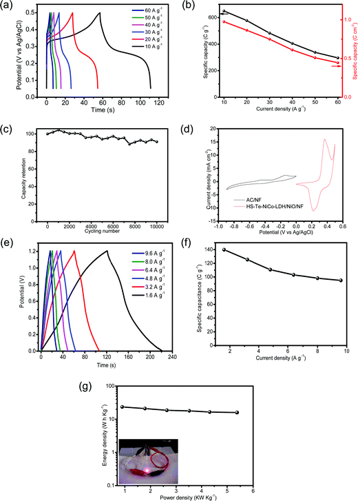
The capacitive performance of HS-Te-NiCo-LDH/NiO/NF was evaluated in the 2 mol L−1 KOH electrolyte. CV curves measured at potentials ranging from 0 to 0.5 V (vs. Ag/AgCl) at 5 mV s−1 exhibited multiple redox current peaks (Fig. 6a and Fig. S11, ESI†), assigned to the faradaic reaction of NiCo-LDH described by eqn (3),39 with the battery-like behavior.8
| M(OH)2 + OH− ↔ MOOH + H2O + e− (M = Ni, Co) | (3) |
Moreover, the kinetics were further evaluated at different scan rates ranging from 1 to 100 mV s−1 (Fig. S12, ESI†). In the range of 1 to 5 mV s−1, the slope of the linear plot of lgIp against lgv was ≈1, indicative of the fact that the transfer/diffusion of electrons and electrolyte ions was the limited step at low scan rates.9,53 At high scan rates (5 to 100 mV s−1), the reduced slope (0.55–0.65) suggested that the surface redox process was the rate-limiting step of the charge storage because the active substances in the electrode were reacted incompletely at such high scan rates.9 The contribution of capacitive and diffusion to the total charge storage was quantified then. As shown in Fig. S13 (ESI†), the capacitive contribution was 67.3% at 1 mV s−1 and as high as 85.7% at 10 mV s−1. That is to say, the dominant charge storage followed the capacitive mechanism that confers high charge storage kinetics and cycling stability on the HS-Te-NiCo-LDH/NiO/NF electrode.54
The galvanostatic charge/discharge (GCD) properties of symmetric supercapacitors HS-Te-NiCo-LDH/NiO/NF//HS-Te-NiCo-LDH/NiO/NF and Te-NiCo-LDH/NF//Te-NiCo-LDH/NF were investigated at 10 A g−1 in the potential window of 0–0.5 V (vs. Ag/AgCl) (Fig. 6b). Their GCD curves have a typical shape. The former exhibited longer charging/discharging times, larger specific capacity, and higher coulombic efficiency, benefiting from the honeycomb-like structure and larger interlayer spacing of HS-Te-NiCo-LDH/NiO/NF to expose more active sites and contain more intercalated ions. The calculated specific capacity and coulombic efficiency of them were 650 (94.7%) and 551 (89.1%) C g−1, respectively.
In view of the advantages of the as-prepared electrode in improving conductivity and transport, it is interesting to examine its performance as a supercapacitor. The specific capacity of HS-Te-NiCo-LDH/NiO/NF//HS-Te-NiCo-LDH/NiO/NF at current densities of 10, 20, 30, 40, 50 and 60 A g−1 were determined as 650 (0.975), 577.5 (0.865), 483 (0.75), 405.5 (0.61), 338.5 (0.51) and 296.5 C g−1 (0.445 C cm−2), respectively, based on the loading active material mass (Fig. 7a and b). The GCD cycling stability was also explored at 30 A g−1 for 10![[thin space (1/6-em)]](https://www.rsc.org/images/entities/char_2009.gif) 000 cycles (Fig. 7c) and there was only a slight decrease (overall 9%) in the specific capacity within the range tested for HS-Te-NiCo-LDH/NiO/NF//HS-Te-NiCo-LDH/NiO/NF. The good stability performance of the HS-Te-NiCo-LDH/NiO/NF electrode may be attributed to the electrolyte reservoirs created by the honeycomb-like structure to accommodate the volume expansion during the cycling test as well as the large interlayer spacing in the α-NiCo-LDH for the transport of electrons and ions.47
000 cycles (Fig. 7c) and there was only a slight decrease (overall 9%) in the specific capacity within the range tested for HS-Te-NiCo-LDH/NiO/NF//HS-Te-NiCo-LDH/NiO/NF. The good stability performance of the HS-Te-NiCo-LDH/NiO/NF electrode may be attributed to the electrolyte reservoirs created by the honeycomb-like structure to accommodate the volume expansion during the cycling test as well as the large interlayer spacing in the α-NiCo-LDH for the transport of electrons and ions.47
These performances of the HS-Te-NiCo-LDH/NiO/NF electrode concerning the specific capacity and the durability were found comparable to or higher than those of NiSe-G,55 TaSe2/PPy,56 or CoSNC (Table S5, ESI†).
For practical purposes, the asymmetric supercapacitor HS-Te-NiCo-LDH/NiO/NF//AC/NF was assembled and evaluated. The CV curves of single anode and cathode (Fig. 7d) revealed the difference in the voltage window of 0–0.5 V (vs. Ag/AgCl) for HS-Te-NiCo-LDH/NiO/NF and −0.9–0 V (vs. Ag/AgCl) for AC/NF, indicating the characteristic of the electrical double-layer capacitor of AC/NF. The GCD profiles (Fig. 7e) have the typical symmetric shape, reflecting the good charge balance between electrodes. At the current density of 1.6, 3.2, 4.8, 6.4, 8.0, and 9.6 A g−1, the specific capacity was 139.8, 125.3, 110.7, 103.1, 98.2, and 95 C g−1, respectively, as calculated from the corresponding discharge profiles based on the total active materials on the positive and negative electrodes (Fig. 7f). The Ragone plot (Fig. 7g) showed a high energy density of 23.46 Wh kg−1 at the power density of 0.89 kW kg−1, and even 15.95 Wh kg−1 at 5.37 kW kg−1. This performance was superior to those of other materials, such as MnCo2O4@Co3O4//AC,57 Ni3V2O8/NG//Fe2VO4/NG,58 and MoSe2-Ni(OH)2//AC.38 Furthermore, two as-prepared asymmetric supercapacitors can power a red LED for hours (inset in Fig. 7g), signifying the potential of the HS-Te-NiCo-LDH/NiO/NF electrode for practical application.
To understand the enhanced OER activity of HS-Te-NiCo-LDH/NiO/NF, the OER behaviors of α-NiCo-LDH, β-NiCo-LDH, and Te-NiCo-LDH (corresponding to HS-Te-NiCo-LDH/NiO/NF) were explored via DFT calculation, as illustrated in Fig. S14 (ESI†).
Fig. 8a depicts the free energy diagrams of typical OER processes involving four elementary steps (HO·, ·O, ·OOH, and O2), where the one with the highest free energy change ΔG is the potential limiting step (PLS).59 The PLS for Te-NiCo-LDH is determined to be the hydroxide adsorption step (O· + OH− → HOO· + e−) having a ΔG3 value of 1.8 eV and a corresponding calculated overpotential η of 0.59 V. The α-Te-NiCo-LDH shows the lowest ΔG values of PLS, revealing the origin of the enhanced OER activity. In addition, a potential of 1.7 V (vs. RHE) was added to the DFT calculation to simulate the OER reaction of these materials under real conditions. The results evinced that the last deprotonation step (HOO· → O2 + H+ + e−) was the PLS. The smallest ΔG value of PLS indicated that α-Te-NiCo-LDH has the lowest energy barrier (1.92 eV, 0.69 V) in the actual OER processes.
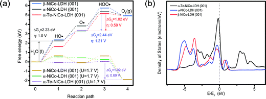 | ||
| Fig. 8 DFT calculations of α-NiCo-LDH, β-NiCo-LDH, and α-Te-NiCo-LDH (001) surface for OER (a). And the total density of states analysis for these electrodes (b). | ||
The density of states (DOS) was derived from an insight into the orbital interactions of α-Te-NiCo-LDH towards the enhanced capacitance (Fig. 8b). Compared to the others, α-Te-NiCo-LDH showed an increased DOS at the Fermi level owing to the larger interlayer spacing of LDH and high covalence of Te in α-Te-NiCo-LDH. The enhanced TDOS at the Fermi level indicated that more carriers were available during the redox reaction, favoring a larger pseudocapacitance.7
Conclusions
The Te-doped NiCo-LDH electrode was synthesized via dynamic oxygen bubble template (DOBT) anodic electrodeposition on the anodized NF substrate. The resultant HS-Te-NiCo-LDH/NiO/NF electrode had a honeycomb-like structure with facile access of electrolyte ions and an active α-NiCo-LDH phase, thus leading to high electrical conductivity and fast reaction kinetics. DFT calculations demonstrated that the lower ΔG values of PLS were the essential reason for the enhanced OER activity of HS-Te-NiCo-LDH/NiO/NF. At the same time, the intensive TDOS at the Fermi level implies the enhanced redox reaction for pseudocapacitive performance of HS-Te-NiCo-LDH/NiO/NF. The high performance in OER efficiency (221 mV for 10 mA cm−2), stability, and capacity (650 C g−1, and 91% retained after 10![[thin space (1/6-em)]](https://www.rsc.org/images/entities/char_2009.gif) 000 cycles) could be ascribed to both the structural and compositional advantages, realized by DOBT and the synergistic effect of component elements. This practice may open a new way for the control synthesis of functional materials with a tuned structure and composition for energy conversion and storage.
000 cycles) could be ascribed to both the structural and compositional advantages, realized by DOBT and the synergistic effect of component elements. This practice may open a new way for the control synthesis of functional materials with a tuned structure and composition for energy conversion and storage.
Conflicts of interest
There are no conflicts to declare.Acknowledgements
This work was supported by the National Natural Science Foundation of China (21771194), the Special Fund for Agro-scientific Research in the Public Interest of China (No. 201503108), the Science & Technology Project of Hunan Province (No. 2017WK2091), and the Fundamental Research Funds for the Central Universities of Central South University (2018zzts383).References
- D. Guan, J. Zhou, Y.-C. Huang, C.-L. Dong, J.-Q. Wang, W. Zhou and Z. Shao, Nat. Commun., 2019, 10, 3755 CrossRef PubMed.
- X. Wang, J. Sunarso, Q. Lu, Z. Zhou, J. Dai, D. Guan, W. Zhou and Z. Shao, Adv. Energy Mater., 2020, 10, 1903271 CrossRef CAS.
- Y. Li and C. Zhao, Chem. Mater., 2016, 28, 5659–5666 Search PubMed.
- W. Sun, Z. Zhou, W. Q. Zaman, L. M. Cao and J. Yang, ACS Appl. Mater. Interfaces, 2017, 9, 41855–41862 CrossRef CAS PubMed.
- V. S. Kale, M. Hwang, H. Chang, J. Kang, S. I. Chae, Y. Jeon, J. Yang, J. Kim, Y.-J. Ko, Y. Piao and T. Hyeon, Adv. Funct. Mater., 2018, 28, 1803786 CrossRef.
- P. Zhang, R. Wang, M. He, J. Lang, S. Xu and X. Yan, Adv. Funct. Mater., 2016, 26, 1354–1364 CrossRef CAS.
- X. Peng, Y. Yan, X. Jin, C. Huang, W. Jin, B. Gao and P. K. Chu, Nano Energy, 2020, 78, 105234 CrossRef CAS.
- F. Zhu, W. Liu, Y. Liu and W. Shi, Chem. Eng. J., 2020, 383, 123150 CrossRef CAS.
- J. Yang, C. Yu, C. Hu, M. Wang, S. Li, H. Huang, K. Bustillo, X. Han, C. Zhao, W. Guo, Z. Zeng, H. Zheng and J. Qiu, Adv. Funct. Mater., 2018, 28, 1803272 CrossRef.
- Y. Zhou, S. Wang, Z. Zhang, N. Williams, Y. Cheng and J. Gu, ChemCatChem, 2018, 10, 3206–3213 CrossRef CAS.
- J. Cao, M. Safdar, Z. Wang and J. He, J. Mater. Chem. A, 2013, 1, 10024–10029 RSC.
- X. Yang, K. Fu, L. Mao, W. Peng, J. Jin, S. Yang and G. Li, Chem. Eng. Sci., 2019, 205, 269–277 CrossRef CAS.
- Z. Yan, Q. Dang, Y. Lu and Z.-H. Liu, Colloids Surf., A, 2017, 520, 32–38 CrossRef CAS.
- N. Zhao, H. Fan, M. Zhang, C. Wang, X. Ren, H. Peng, H. Li, X. Jiang and X. Cao, J. Alloys Compd., 2019, 796, 111–119 CrossRef CAS.
- R. Fan, Q. Mu, Z. Wei, Y. Peng and M. Shen, J. Mater. Chem. A, 2020, 8, 9871–9881 RSC.
- C. Tang, Z. L. Zhao, J. Chen, B. Li, L. Chen and C. M. Li, Electrochim. Acta, 2017, 248, 243–249 CrossRef CAS.
- Z. Pu, Y. Luo, A. M. Asiri and X. Sun, ACS Appl. Mater. Interfaces, 2016, 8, 4718–4723 CrossRef CAS PubMed.
- S. Zhao, R. Jin, H. Abroshan, C. Zeng, H. Zhang, S. D. House, E. Gottlieb, H. J. Kim, J. C. Yang and R. Jin, J. Am. Chem. Soc., 2017, 139, 1077–1080 CrossRef CAS PubMed.
- L.-L. Feng, G. Yu, Y. Wu, G.-D. Li, H. Li, Y. Sun, T. Asefa, W. Chen and X. Zou, J. Am. Chem. Soc., 2015, 137, 14023–14026 CrossRef CAS PubMed.
- U. De Silva, J. Masud, N. Zhang, Y. Hong, W. P. R. Liyanage, M. Asle Zaeem and M. Nath, J. Mater. Chem. A, 2018, 6, 7608–7622 RSC.
- C. Kartick, K. Paramita and M. Rashmi, Electrochim. Acta, 2019, 318, 901–912 CrossRef.
- Q. Gao, C. Huang, Y. Ju, M. Gao, J. Liu, D. An, C. Cui, Y. Zheng, W. Li and S. Yu, Angew. Chem., Int. Ed., 2017, 56, 7769–7773 CrossRef CAS PubMed.
- Q. Wang, J. Zhu, H. Wang, S. Yu and X. Wu, Mater. Today Energy, 2019, 11, 199–210 CrossRef CAS.
- H. Han, K. M. Kim, J. H. Ryu, H. J. Lee, J. Woo, G. Ali, K. Y. Chung, T. Kim, S. Kang, S. Choi, J. Kwon, Y.-C. Chung, S. Mhin and T. Song, Nano Energy, 2020, 75, 104945 CrossRef CAS.
- D. Zhang, L. Peng, Z. Yang, Y. Yang and H. Li, Inorg. Chem., 2019, 58, 15841–15852 CrossRef CAS PubMed.
- S. K. Meher and G. R. Rao, J. Power Sources, 2012, 215, 317–328 CrossRef CAS.
- J. Zhang, Y. Yang, Z. Zhang, X. Xu and X. Wang, J. Mater. Chem. A, 2014, 2, 20182–20188 RSC.
- N. Comisso, S. Cattarin, P. Guerriero, L. Mattarozzi, M. Musiani and E. Verlato, Electrochim. Acta, 2016, 200, 259–267 CrossRef CAS.
- J. Chang, S. Lee, T. Ganesh, R. S. Mane, S. Min, W. Lee and S. Han, J. Electroanal. Chem., 2008, 624, 167–173 CrossRef CAS.
- B. J. Plowman, L. A. Jones and S. K. Bhargava, Chem. Commun., 2015, 51, 4331–4346 RSC.
- G. Wang, Z. Yang, Y. Du and Y. Yang, Angew. Chem., Int. Ed., 2019, 58, 15848–15854 CrossRef CAS PubMed.
- Y. W. Yao, X. Chen, N. C. Yu, H. S. Dong and H. R. Wang, J. Electrochem. Soc., 2017, 164, E48–E52 CrossRef CAS.
- J. Wang, L. Ji and Z. Chen, ACS Catal., 2016, 6, 6987–6992 CrossRef CAS.
- S. L. Medway, C. A. Lucas, A. Kowal, R. J. Nichols and D. Johnson, J. Electroanal. Chem., 2006, 587, 172–181 CrossRef CAS.
- M. S. Wu, C. H. Yang and M. J. Wang, Electrochim. Acta, 2008, 54, 155–161 CrossRef CAS.
- X. Wang, Y. Zheng, J. Yuan, J. Shen, J. Hu, A.-J. Wang, L. Wu and L. Niu, Electrochim. Acta, 2017, 224, 628–635 CrossRef CAS.
- L. Liu, T. Guan, L. Fang, F. Wu, Y. Lu, H. Luo, X. Song, M. Zhou, B. Hu, D. Wei and H. Shi, J. Alloys Compd., 2018, 763, 926–934 CrossRef CAS.
- B. Kirubasankar, P. Palanisamy, S. Arunachalam, V. Murugadoss and S. Angaiah, Chem. Eng. J., 2019, 355, 881–890 CrossRef CAS.
- Y. Guo, X. Hong, Y. Wang, Q. Li, J. Meng, R. Dai, X. Liu, L. He and L. Mai, Adv. Funct. Mater., 2019, 29, 1809004 CrossRef.
- M. Tavakkoli, M. Nosek, J. Sainio, F. Davodi, T. Kallio, P. M. Joensuu and K. Laasonen, ACS Catal., 2017, 7, 8033–8041 CrossRef CAS.
- M. Liu, X. Li and W. Chen, Electrochim. Acta, 2017, 247, 426–434 CrossRef CAS.
- J.-M. Song, Y.-Z. Lin, Y.-J. Zhan, Y.-C. Tian, G. Liu and S.-H. Yu, Cryst. Growth Des., 2008, 8, 1902–1908 CrossRef CAS.
- A. K. Samal and T. Pradeep, Langmuir, 2010, 26, 19136–19141 CrossRef CAS PubMed.
- J. Yu, Y. Zhong, X. Wu, J. Sunarso, M. Ni, W. Zhou and Z. Shao, Adv. Sci., 2018, 5, 1800514 CrossRef PubMed.
- M. Zhu, J. Miao, X. Duan, D. Guan, Y. Zhong, S. Wang, W. Zhou and Z. Shao, ACS Sustainable Chem. Eng., 2018, 6, 15737–15748 CrossRef CAS.
- M. Qian, S. Cui, D. Jiang, L. Zhang and P. Du, Adv. Mater., 2017, 29, 1704075 CrossRef PubMed.
- W. Lu, J. Shen, P. Zhang, Y. Zhong, Y. Hu and X. W. Lou, Angew. Chem., Int. Ed., 2019, 58, 15441–15447 CrossRef CAS PubMed.
- H. Xing, Y. Lan, Y. Zong, Y. Sun, X. Zhu, X. Li and X. Zheng, Inorg. Chem. Commun., 2019, 101, 125–129 CrossRef CAS.
- Y.-H. Fang and Z.-P. Liu, ACS Catal., 2014, 4, 4364–4376 CrossRef CAS.
- R. Akram, M. A. Ud Din, S. U. Dar, A. Arshad, W. Liu, Z. Wu and D. Wu, Nanoscale, 2018, 10, 5658–5666 RSC.
- J. Xu, H. Zhang, P. Xu, R. Wang, Y. Tong, Q. Lu and F. Gao, Nanoscale, 2018, 10, 13702–13712 RSC.
- Z. Sadighi, J. Liu, L. Zhao, F. Ciucci and J. K. Kim, Nanoscale, 2018, 10, 22549–22559 RSC.
- T. Brezesinski, J. Wang, S. H. Tolbert and B. Dunn, Nat. Mater., 2010, 9, 146 CrossRef CAS PubMed.
- D. Zhang, Z. Yang, Y. Yang, H. Li and X. Wang, Chem. Commun., 2020, 56, 15549–15552 RSC.
- B. Kirubasankar, V. Murugadoss, J. Lin, T. Ding, M. Dong, H. Liu, J. Zhang, T. Li, N. Wang, Z. Guo and S. Angaiah, Nanoscale, 2018, 10, 20414–20425 RSC.
- M. Wang, L. Zhang, Y. Zhong, M. Huang, Z. Zhen and H. Zhu, Nanoscale, 2018, 10, 17341–17346 RSC.
- J.-J. Zhou, X. Han, K. Tao, Q. Li, Y.-L. Li, C. Chen and L. Han, Chem. Eng. J., 2018, 354, 875–884 CrossRef CAS.
- M. Guo, J. Balamurugan, N. H. Kim and J. H. Lee, Appl. Catal., B, 2018, 239, 290–299 CrossRef CAS.
- C. Guan, W. Xiao, H. Wu, X. Liu, W. Zang, H. Zhang, J. Ding, Y. P. Feng, S. J. Pennycook and J. Wang, Nano Energy, 2018, 48, 73–80 CrossRef.
Footnote |
| † Electronic supplementary information (ESI) available. See DOI: 10.1039/d1ma00688f |
| This journal is © The Royal Society of Chemistry 2022 |

