 Open Access Article
Creative Commons Attribution 3.0 Unported Licence
Solid solutions based on BaZn2Si2O7 with thermal expansions from negative to highly positive – a review
Christian
Thieme
 *a and
Christian
Rüssel
 b
b
aFraunhofer-Institut für Mikrostruktur von Werkstoffen und Systemen IMWS, Walter-Hülse-Straße 1, D-06120 Halle (Saale), Germany. E-mail: christian.thieme@imws.fraunhofer.de
bOtto-Schott-Institut für Materialforschung, Jena University, Fraunhoferstr. 6, D-07743 Jena, Germany
First published on 18th July 2022
Abstract
The compound BaZn2Si2O7 shows a transition from a monoclinic low temperature phase to an orthorhombic high temperature phase at 280 °C which is accompanied by an increase in the volume of 3.3%. The temperature of the phase transition can be shifted to higher temperature by a replacement of Zn2+ by Mg2+ or the divalent transition metal cations, Mn2+, Co2+, Ni2+ or Cu2+ as well as by the replacement of Si4+ by Ge4+. By contrast, the replacement of Ba2+ by Sr2+ leads to the shift of the phase transition to lower temperatures. The coefficient of thermal expansion of the low temperature phase is exceptionally high and in the range from 10 to 15 10−6 K−1, while that of the high temperature phase is small or even negative. The reason of the latter effect is a rotation of bridged ZnO4 tetrahedra in opposite directions. This results in a strongly negative thermal expansion of the b-axis, while the expansion of the a- and c-axes are positive. Although melts of the stoichiometric compounds do not build a continuous network, glass formation can be achieved by the addition nucleation inhibitors, such as ZrO2, Al2O3 or La2O3 or an excess of SiO2. The quenched glasses crystallize at the surface while bulk crystallization is not observed. This changes if noble metals or higher concentrations of ZrO2, WO3 or P2O5 are added to the glass, then also bulk crystallization is possible. Homogeneously crystallized glass ceramics can also be obtained, by sinter crystallization of powdered glass or using sol–gel derived crystalline powders. Adjusting the composition of the respective solid solutions enables to tailor the coefficient of thermal expansion from negative to highly positive values.
1. Introduction
The compound BaZn2Si2O7 shows a transition from a low to a high temperature phase at around 280 °C, accompanied by a steep increase in volume of 3.3%.1 The low temperature phase shows a high coefficient of thermal expansion (CTE), which is in the range from 10–15 × 10−6 K−1, while the CTE of the high temperature phase is very low or even negative.2 The stoichiometric composition BaZn2Si2O7 does not form a glass, however, the addition of some SiO2 (or other oxides) leads to glass formation. From such a glass, the BaZn2Si2O7 based phases can be crystallised by thermal treatment.3,4During the phase transformation, the crystal structure changes from monoclinic (<280 °C) to orthorhombic (>280 °C). The monoclinic low temperature phase (LT-phase) possesses a high (CTE) of 16 × 10−6 K−1, while the CTE of the high temperature phase (HT-phase) is small or even negative.1 In BaZn2Si2O7, a total or partial replacement of Zn2+ by other divalent cations shifts the phase transition temperature to higher values.2,5 This enables the preparation of materials with exceptionally high CTEs, also in the range from room temperature to 1000 °C, which are required for crystallizing glass seals to join metals, e.g. for high temperature solid oxide fuel cells (SOFC) or other high temperature reactors.6–8
Otherwise, a partial substitution of Ba2+ by Sr2+ shifts the phase transition temperatures to lower values, even below room temperature.9 This enables the preparation of materials with a low thermal expansion.10 Such materials, however, based on lithium aluminosilicates and not on Ba1−xSrxZn2Si2O7, are nowadays used for a large variety of applications, such as cook top panels, telescope mirrors, furnace windows and various optical devices.11–13
Negative thermal expansion at room temperature and higher is an uncommon physical property, since most materials expand with increasing temperature. The most common materials with zero thermal expansion are silicates based on lithium aluminosilicates, such as beta-quartz and beta-eucryptite.14 These phases can be crystallized from glasses and enable the fabrication of large ceramic specimens, e.g. telescope mirror blanks with diameters of several meters.15 Other phases with negative thermal expansion which can be crystallized from glasses are MB2Al2O7 with M = Ba, Ca, Sr.16–18 Besides, ZrW2O8 and materials derived hereof are among the most commonly known negative thermal expansion phases.19,20 However, they cannot be crystallized from glasses. ZrO2 as well as WO3 do not act as glass formers. To achieve glass formations, high quantities of other glass formers such as B2O3 or SiO2 are necessary. If from such glasses, ZrW2O8 might be crystallized (although not described in the literature), the high quantities of residual glass phase cannot lead to zero thermal expansion.
In the following, the formation of solid solutions based on BaZn2Si2O7 is described. The replacement of Ba2+, Zn2+ or Si4+ by other ions strongly affects the temperature attributed to the phase transition from the low to the high temperature phase and hence also the CTE. It is further described, how bulk materials based on these solid solutions can be prepared by sintering or by glass crystallization and how the CTE can be tailored.
2. Crystal structure and thermal expansion of pure BaZn2Si2O7
The compound BaZn2Si2O7 has a high coefficient of thermal expansion up to a temperature of 280 °C. The attributed LT-phase is monoclinic with the space group C2/c.1 Then, a transition to a high temperature phase, with the orthorhombic space group Ccm21, occurs. The thermal expansion behaviour is shown in Fig. 1. The coefficient of thermal expansion (CTE) of the LT-phase is exceptionally high and in the range of 10–15 × 10−6 K−1. The phase transition is accompanied by a steep increase in volume of around 3.3%.1 The HT-phase has a small or even negative CTE. Fig. 1 shows a comparison of results from dilatometry using a sintered powder compact and high-temperature X-ray powder diffraction (HT-XRD). To plot both data sets on one axis, the volumes from HT-XRD were converted to corresponding changes in length by taking the cube root. The thermal expansion measured by dilatometry and XRD are almost identical below as well as above the phase transition. The height of the volume jump, however, is different. In dilatometric measurements of compressed and sintered powders, the height of this jump cannot be exactly reproduced because the compact sample is damaged during phase transition.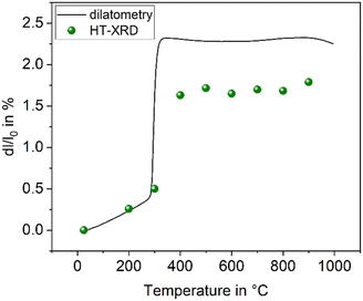 | ||
| Fig. 1 Thermal expansion of BaZn2Si2O7. Redrawn based on ref. 5. | ||
Fig. 2 shows the crystal structures of LT- and HT-phase, respectively. Both structures are fairly similar: silicon and zinc are both fourfold coordinated and, in both cases, two silicon tetrahedra are bridged by oxygen. ZnO4-tetrahedra form chains aligned along the crystallographic c-axis. The Ba2+ ions are located in channels and possess a quadratic pyramidal coordination where the Ba–O bond length of the apex is notably longer. Please note that the monoclinic and the orthorhombic unit cells are defined in a different manner and hence it is favourable to compare different planes and directions. For all subsequent descriptions, the crystallographic directions have been renamed. This facilitates to compare the HT- and LT-phases as well as their crystallographic directions. The directions were defined according to Fig. 2.
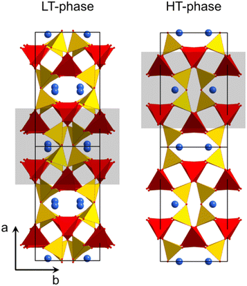 | ||
| Fig. 2 Crystal structure of LT- and HT-BaZn2Si2O7.1,21 The grey rectangles mark similar structural units, which convert into each other during phase transition. | ||
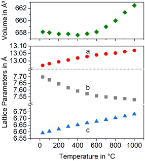
In Fig. 3, the changes in the lattice constants of both the low and the high temperature phase are shown. From room temperature to 280 °C, the lengths of a- and b-axes increase strongly, while the CTE of the c-axis is smaller. The phase transition is clearly seen and accompanied by an increase of the a- and b-axes by 1.3 and 3.6%, respectively, while the c-axis contracts by around 1.4%. More notably is the behaviour above the phase transition temperature: while the lengths of a- and c-axes increase as expected, the b-axis contracts, i.e., the CTE in the direction of the b-axis is negative.
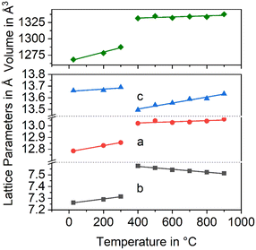 | ||
| Fig. 3 Lattice constants of BaZn2Si2O7 as a function of temperature. Data taken from ref. 2. | ||
3. Solid solutions based on BaZn2Si2O7
3.1 Substitution of Zn2+ by divalent metal cations
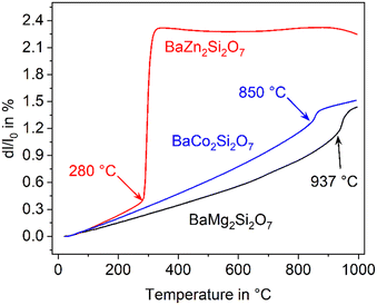
In the literature, the total replacements of Zn2+ by Mg2+ or Co2+ and also, a partial replacement of Zn2+ by Ni2+ were reported.2,5,22 In any case, a substitution of Zn2+ results in a shift of the phase transition to higher temperature. The thermal expansions of the end members of the solid solution series containing Zn2+, Co2+ and Mg2+ are displayed in Fig. 4. In the case of the dilatometry results presented in Fig. 4, the phase transition changes the microstructure of the specimens considerably and the data allow only a purely qualitative consideration. Especially in the case of BaZn2Si2O7, very different dilatometric curves can be found in the literature (see ref. 2 and 5), which is due to the formation of cracks during phase transition. BaZn2−yMySi2O7 solid solutions show qualitatively the same behaviour, however, the phase transition is continuously shifted to higher temperatures with decreasing Zn2+ concentration as shown in Fig. 5. Simultaneously, the volume effect, which runs parallel to the phase transition decreases and is by far not as high as for BaZn2Si2O7.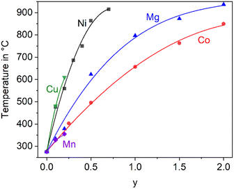 | ||
| Fig. 5 Temperature of the phase transition for solid solutions of BaZn2−yMySi2O7 with M = Co, Cu, Mg, Mn, and Ni.2,5,22,23 The lines are drawn as a guide for the eyes. | ||
Mg2+ and Co2+ may totally replace Zn2+ without changing the crystal structure, while in the case of Cu2+ and Ni2+, a 100% substitution is not possible. In the literature, an end member BaCu2Si2O7 is reported, however, the crystal structure is different from the BaZn2Si2O7 phases.24 A complete substitution of Zn2+ by Mn2+ is also reported in ref. 25, however, phase transition temperatures above room temperature are only given for a lower degree of substitution (compare Fig. 5).
3.2 Substitution of Ba2+ by Sr2+
The substitution of Ba2+ by Sr2+ has the opposite effect as the Zn2+ replacement. If only 5% of Ba2+ are replaced by Sr2+, the phase transition temperature decreases notably. This is shown in Fig. 6 for different replacements of Ba2+ against Sr2+. Already if 10% of Ba2+ are replaced by Sr2+, the phase transition temperature cannot be observed above room temperature. It is not exactly known whether the phase transitions occur at temperatures below room temperature, however, if 20% Ba2+ are substituted against Sr2+, the high temperature phase is still stable at 100 K.26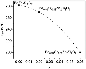 | ||
| Fig. 6 Phase transition temperature (dilatometry) as a function of x in Ba1−xSrxZn2Si2O7 solid solutions. | ||
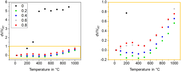
Fig. 7 presents the thermal expansion of Ba1−xSrxZn2Si2O7 samples for various x-values. The CTEs are small up to a temperature of 400 °C and then increase. A smaller degree of substitution is favourable to achieve a negative CTE. Fig. 8 shows the lattice parameters of the Ba0.6Sr0.4Zn2Si2O7 solid solution as a function of the temperature. It is shown that the a-axis as well as the c-axis expand during heating, while the b-axis strongly contracts. The volume of the unit cell decreases up to a temperature of 400 °C and then increases again.
 | ||
| Fig. 8 Lattice constants and unit cell volume of the Ba0.6Sr0.4Zn2Si2O7 solid solutions as a function of temperature. | ||
To study the origin of the negative CTE, single crystal X-ray diffraction was performed at temperatures of 220, 293 and 353 K. Fig. 9 shows a part of the network formed by ZnO4 (red) and SiO4 tetrahedra (yellow). The crystallographic c-axis is perpendicular to the drawing plane, while the b-axis is arranged vertically. With increasing temperature, two bridged ZnO4 tetrahedra rotate in opposite directions. Simultaneously, the ZnO4- and SiO4-units, deform. This leads to a shortening of the crystallographic b-axis.27 These experimental observations were confirmed by simulations using density functional theory.27
 | ||
| Fig. 9 Part of the network formed by ZnO4 (red) and SiO4 tetrahedra (yellow). With increasing temperature, ZnO4 tetrahedra rotate, which results in a stretching of the ZnO4-chain in the direction of the c-axis and a shortening in the b-direction. Redrawn from ref. 9. | ||
The phase transition temperatures as a function of the chemical compositions were calculated by density functional theory simulations.28 In Table 1, the calculated phase transition temperatures as well as those determined by dilatometry or DSC are summarized. The differences in the phase transition temperatures can be explained by the higher inaccuracy of simulated phase transition temperatures.
| Chemical composition (mol%) | T t experimental (°C) | T t calculated (°C) |
|---|---|---|
| a Determined by DSC. b Determined by dilatometry. c Calculated values. | ||
| BaZn2Si2O7 | 277a | 222c |
| BaZn1.5Mg0.5Si2O7 | 623a | 567c |
| BaZnMgSi2O7 | 797a | 775c |
| BaZn0.5Mg1.5Si2O7 | 873a | 980c |
| BaMg2Si2O7 | 937a | 869c |
| Ba0.5Sr0.5ZnMgSi2O7 | 392a | 274c |
| Ba0.75Sr0.25Zn0.5Mg1.5Si2O7 | 588b | 548c |
3.3 Substitution of Ba2+ by Sr2+ and Zn2+ by other divalent cations
In analogy to the replacement of Zn2+ in the BaZn2Si2O7 lattice, also in the Ba1−xSrxZn2Si2O7 lattice, Zn2+ can be substituted by other divalent cations. Generally, Zn2+ (ionic radius from ref. 29: 74 pm) can be substituted in the Ba1−xSrxZn2Si2O7 lattice by cations with similar ionic radii. The latter should be in the range from 80 pm (Mn2+) to 92 pm (Co2+).In Table 2, the mean CTEs from HT-XRD of different compositions are summarized. The pure Zn-compound has a CTE of 0.7 × 10⁻⁶ K−1. This value decreases when Zn2+ is substituted. A higher degree of substitution with one and the same element leads to smaller CTEs. If the degree of substitution is kept constant, the lowest CTE is observed if Zn2+ is substituted by ions, which strongly shift the phase transition temperature. In Fig. 5, the effect of substitution on the phase transition temperature is shown. Ni2+ and Cu2+ have a larger effect than equimolar concentrations of the other ions and their incorporations lead to smallest CTEs. The CTE is lowest, if the degree of substitution is slightly below the limit which leads to the formation of the LT-phase with high thermal expansion.
| Element M | CTE30–300°C in [10−6 K−1] |
|---|---|
| Mg | 0.5 |
| Co | 0.1 |
| Mn | −0.3 |
| Ni | −1.6 |
| Cu | −2.0 |
3.4 Substitution of Si4+ by Ge4+
In a BaZn2Si2O7 lattice, up to 75% Si4+ can be replaced by Ge4+ without changing the phase while larger Ge4+-concentrations lead to the formation of secondary phases, such as Zn2GeO4.30,31 As shown in Fig. 10, the temperature of the phase transition increases linearly with increasing Ge concentration from 280 °C for BaZn2Si2O7 to around 700 °C for BaZn2Si0.5Ge1.5O7 an hence, in analogy to the substitution of Zn2+ by other divalent cations, the monoclinic low temperature phase is increasingly stabilized.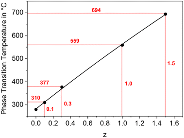 | ||
| Fig. 10 Phase transition temperature of BaZn2Si2−zGezO7 solid solutions as a function of the Ge concentration. | ||
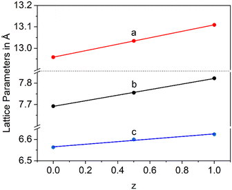
In a Ba1−xSrxZn2Si2O7 solid solution, equimolar replacement of 50% of Si4+ by Ge4+, still results in the formation of the orthorhombic high temperature phase. As shown in Fig. 11, the unit cell parameters increase linearly with the degree of substitution.
Fig. 12 shows lattice parameters of the orthorhombic high temperature phase with the composition Ba0.5Sr0.5Zn2SiGeO7. In analogy to Ba0.5Sr0.5Zn2Si2O7, the a- and the c-axis expand during heating while the b-axis contracts. The volume of the unit cell decreases up to a temperature of 400 °C and then increases.
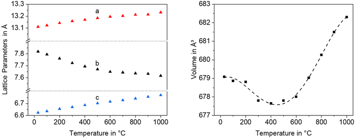 | ||
| Fig. 12 Lattice parameters and unit cell volume of Ba0.5Sr0.5Zn2SiGeO7 as a function of temperature. | ||
3.5 Thermal expansion and its anisotropy of solid solutions based on Ba1−xSrxZn2Si2O7
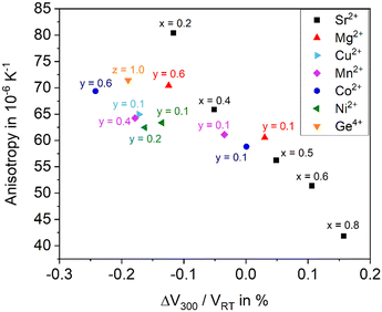
As shown above, the thermal expansion of solid solutions based on BaZn2Si2O7 strongly depends on the substitution of Ba2+ by Sr2+, of Zn2+ by other bivalent elements and of Si4+ by Ge4+. Another important issue, however, is the degree of anisotropy of the thermal expansion. Generally, in all Ba1−xSrxZn2Si2O7 solid solutions, the CTE of the crystallographic b-axis is strongly negative, while those of the a- and c-axes are positive. In the following, as a measure of the anisotropy, the difference of the CTEs of the axis with the highest and the smallest were taken (see Fig. 13). The data were all extracted from high temperature XRD. The “anisotropy” values were all in the range from 42 to 81 × 10−6 K−1.There is a general trend that samples with higher CTE possess a smaller anisotropy. For example, for the series Ba1−xSrxZn2Si2O7 (without substitution of the Zn2+ position) the anisotropy decreases continuously from x = 0.2 to x = 0.8 (see black squares).
All other data are attributed to samples with the composition Ba0.5Sr0.5Zn2−yMySi2−zGezO7. For a particular cation M2+ substituting y = 0.1 Zn2+, the CTE gets more negative, however, the anisotropy increases. This effect is most pronounced for Cu2+, followed by Ni2+, and Mn2+. Also, in the case of Co2+ and Mg2+, the effect is observed. Substitution of Si4+ by Ge4+ has a similar effect. Increasing y-values (i.e. increasing substitutions of Zn) lead to further increasing anisotropies and to further more negative CTEs in most cases. In summary, the maximum concentration of divalent cations substituting Zn2+, where still the high temperature phase occurs leads to the most negative CTEs, whereas a larger degree of substitution results in a decrease of the anisotropy.
4. Glass formation in the BaO/ZnO/SiO2 and BaO/SrO/ZnO/SiO2 systems
The stoichiometric compounds Ba1−xSrxZn2Si2O7 and BaZn2Si2O7 do not form glasses. That is due to the lack of a network structure. Assuming BaO and ZnO occur as network modifier, a continuous network is not formed and the mean network connectivity is equal to 1. That means, an Si2O76− structure should be predominant which charges are compensated in the average by one Ba2+ and two Zn2+ ions. This simple consideration fully explains that stoichiometric melts crystallize during cooling. The glass formation ranges of the systems BaO–ZnO–SiO2 and SrO–ZnO–SiO2 are given in ref. 32–34. To overcome the problem of spontaneous crystallization, the concentration of network formers has to be increased.In the case of the system BaO/ZnO/SiO2 from which mainly materials with high CTEs should be crystallized, the composition 18 BaO·27 ZnO·55 SiO2 proved to be suitable for controlled precipitation of BaZn2Si2O7. Here, the network connectivity is 2.36 which is just a little bit above the percolation threshold according to the percolation limit of 2.3.35 At a lower network connectivity, the network is “floppy”, i.e. no more rigid and nucleation is facilitated. Therefore, the crystallization tendency should be comparatively low in comparison to a glass with the stoichiometry 20 BaO·40 ZnO·40 SiO2. In the 18 BaO·27 ZnO·55 SiO2 composition, the Ba/Zn ratio was chosen larger than 0.5 because an excess of barium should result in the additional crystallization of barium silicates, which also have high CTEs in the range from 12 to 15 × 10−6 K−1, but the crystallization of Zn2SiO4 (willemite) with its exceptionally small CTE should be avoided.36–38
In the system SrO–ZnO–SiO2, a compound with very high thermal expansion does not precipitate. In a glass with the mol% composition 16 SrO·35 ZnO·45 SiO2·1 ZrO2·1 La2O3·2 B2O3, Sr2ZnSi2O7 and Zn2SiO4 as major crystalline phases are described.39 The crystallized glass has a CTE of around 7 × 10⁻⁶ K−1. Higher SrO-concentrations may additionally lead to the precipitation of SrSiO3.40,41 The system BaO/SrO/ZnO/SiO2 has a lower tendency towards crystallization than the system BaO/ZnO/SiO2. This should be due to the occurrence of three different network modifying components which decreases the tendency towards crystallization. The glass with the composition 8 BaO·8 SrO·34 ZnO·50 SiO2 can be obtained by melt quenching. It does not form a real network structure, however, the network connectivity (assuming again BaO and ZnO acting as network modifiers) is equal to two and hence something like a chain structure or a combined ring and chain structure should be formed. Another, more complex glass composition in this system is 8 BaO·8 SrO·35 ZnO·45 SiO2·1 ZrO2·1 La2O3·2 B2O3. Here, the concentration of ZnO was increased by 3 mol% (in comparison to that of the alkaline earths) to avoid the crystallization of high CTE barium silicates. Furthermore, the tendency towards crystallization was decreased by the addition of SiO2, B2O3, ZrO2 and La2O3. Minor concentrations of the latter two are well known nucleation inhibitors in melts of high basicity.42,43 It should be noted, however, that higher concentrations of ZrO2 have a nucleating effect in many systems.44
If glasses containing both BaO and SrO together with ZnO and SiO2 are crystallized, the stability range of the HT-phase is much smaller than of ceramics obtained via mixed oxide routes.39,45 While in the case of ceramics, the HT-phase is stable for 0.2 < x < 0.8, in a glass with the same BaO/SrO ratio, both the LT- and the HT-phases are formed. The sole crystallization of the HT phase from glasses is observed for 0.5 < x < 0.8.39 Higher SrO concentrations lead to the formation of Sr2ZnSi2O7 and Zn2SiO4. The different phase formation of compact samples in comparison to powdered samples is supposedly due to the anisotropy of the thermal expansion which leads to notable internal stresses during cooling.
The phase transitions, observed in crystalline BaZn2Si2O7 and isostructural compounds, can also be found in the respective crystallized glasses. In solid solutions precipitated from glasses, the phase transitions are shifted to higher values. In a glass with the molar composition 19 ZnO·27 BaO·54 SiO2, from which BaZn2Si2O7 was precipitated, the phase transition temperature occurs at 380 °C, i.e. around 100 K higher than in the stoichiometric crystalline phase.46 Furthermore, the jump in volume is not observed; instead, a kink is visible.
5. Crystallization behaviour of glasses
Glasses in the system BaO/ZnO/SiO2 show surface crystallization. Compounds, such as SrO, MgO, MnO, CoO, NiO, CuO, or GeO2 used to crystallize solid solutions do not promote bulk nucleation. Nevertheless, the addition of nucleation agents, noble metals or oxidic compounds may lead to bulk nucleation. The latter are oxides of metals with high valency mostly in the range of four to six, such as TiO2, ZrO2 or a mixture hereof.44,47–495.1 Surface crystallization
When thermally treated at temperatures not too far above Tg, glasses in the BaO/ZnO/SiO2 and BaO/SrO/ZnO/SiO2 systems show surface crystallization. In the BaO/SrO/ZnO/SiO2 system, nucleation at the surface already leads to an orientation of the a- or b-axis parallel to the surface.50 The highest growth velocity, however, is along the crystallographic c-axis (see Fig. 14). The crystals grow for some microns along the surface and then the growth direction changes continuously until the c-axis grows towards the bulk.51 A possible explanation might be oriented nucleation. However, this effect, which is described in a recent review, was not proven in detail for the glasses described here.52 The change in the growth direction is denoted as “crystal selection” or “survival of the fastest” and is due to the fact that crystals hinder each other during crystal growth and only crystals which are oriented with their fastest growing axis approximately perpendicular to the surface may survive.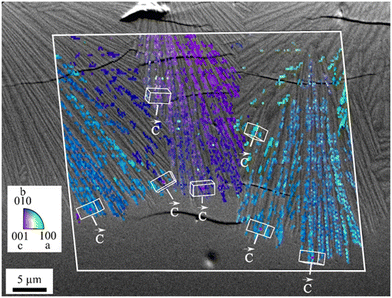 | ||
| Fig. 14 Orientation of surface crystals with growing direction from the top to the bottom. The micrograph shows a cross section after crystallization for 1.5 h at 790 °C. The colour coded part of the micrograph is a superposition with an inverse pole figure map of an EBSD scan. (redrawn from ref. 50). | ||
In the SEM micrograph (Fig. 14), a surface crystallized sample with the composition 8 BaO·8 SrO·34 ZnO·50 SiO2 thermally treated 790 °C for 1.5 h is presented. The micrograph shows some cracks perpendicular to the long axis, the c-axis of the respective crystals which are supposedly formed during cooling of the sample. The thicknesses of the layers increase linearly with time (within the accuracy of the measurement). Hence, compounds which are not incorporated in the crystal, i.e. some excess SiO2 are not increasingly enriched at the growth front and do not form a diffusion barrier which decelerates crystal growth with time.53
5.2 Bulk nucleation, effect of nucleation agents
| 2Ag+ + Sb3+ → 2Ag + Sb5+ | (1) |
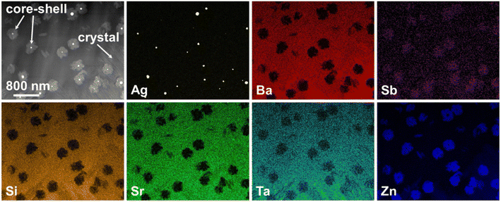
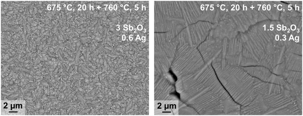
In principle, bulk nucleation can be achieved by the addition of platinum as well as of silver. In the case of silver, the Ba0.5Sr0.5Zn2Si2O7 crystals do not directly grow on the silver nano crystals but an intermediate phase is formed, which seems to be an antimony doped willemite type (Zn2SiO4) phase.61 Only the formation of this core shell structure (see Fig. 15) initiates Ba0.5Sr0.5Zn2Si2O7 crystallization. Fig. 16 shows micrographs of BaO/SrO/ZnO/SiO2 based glass ceramics with different Ag2O and Sb2O3 concentrations, crystallized under the same conditions (nucleation: 675 °C for 20 h, crystal growth; 760 °C for 5 h). Both samples show as main crystalline phase Ba0.5Sr0.5Zn2Si2O7 as well as metallic silver (see small bright spots). The sample with Ag and Sb2O3 concentrations of 0.3 and 1.5 mol%, respectively shows a fairly coarse microstructure and numerous cracks. By contrast, the sample with 0.6 mol% Ag and 3 mol% Sb2O3 possesses a much finer microstructure. That is due to the occurrence of much more Ag particles. The twice as high silver concentration but also the higher Sb3+ concentration led to a much more effective nucleation and much smaller Ba0.5Sr0.5Zn2Si2O7 crystals.
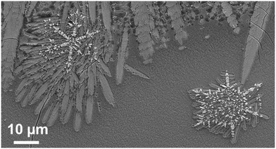
Fig. 17 shows the microstructure of a glass–ceramic with the composition 7.5 BaO·7.5 SrO·34 ZnO·43 SiO2·7 ZrO2·1 TiO2 crystallized at 750 °C for 48 h and at 840 °C for 30 min.63 Large crystals within the glass volume can be found, which seem to start growing from only one nucleus. Furthermore, crystal agglomerates of the Ba0.5Sr0.5Zn2Si2O7 phase with diameters in the range from 40 to 60 μm are observed. The agglomerates consist of bundles of various crystals which all have similar orientations (see for example the crystal in the upper right corner of Fig. 17). The agglomerates are composed by 6 to 10 bundles with different orientations. The long dimension of the crystals is the crystallographic c-axis, as evidenced by electron backscatter diffraction. The nuclei themselves which possibly consist of ZrO2 could not be detected.
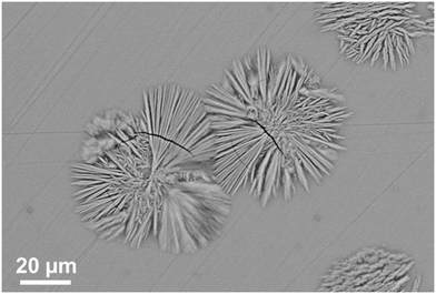 | ||
| Fig. 17 Microstructure of a sample with the composition 7.5 BaO·7.5 SrO·34 ZnO·43 SiO2·7 ZrO2·1 TiO2 crystallized at 750 °C for 48 h and at 840 °C for 30 min. | ||
Fig. 18 shows an SEM micrograph of a sample with the composition 9.4 BaO·9.4 SrO·37.6 ZnO·37.6 SiO2·4 P2O5·2 Ce2O3 which is equal to 18.8 (Ba0.5Sr0.5Zn2Si2O7)·4 P2O5·2 Ce2O3.65 The addition of P2O5 and Ce2O3 to the stoichiometric compound obviously extends the glass forming range notably. During thermal treatment at 690 °C for 20 h and subsequently at 850 °C for 1 h, first surface crystallization of Ba0.5Sr0.5Zn2Si2O7, Zn2SiO4, and CeO2 can be observed. Furthermore, the crystallization of (Ba,Sr)5(PO4)3Cl, a phase with the hexagonal apatite (Ca5P3O12OH) structure (space group P63/m), occurred (see the bright crystals with hexagonal shape in Fig. 18). The c-axes of these crystals are oriented approximately perpendicular to the cut plane. The crystals growing around them are Ba0.5Sr0.5Zn2Si2O7 which is also oriented with the c-axis in the same manner and hence epitaxial growth on the apatite crystal is assumed.
6. Sintering of glass powders and sol–gel derived glasses
6.1 Sinter crystallization of glasses
If glasses are powdered, pressed into shape and subsequently sintered, the preparation procedure is denoted as “sinter crystallization”. It is assumed that first sintering due to viscous flow occurs and subsequently, nucleation at the inner surface of the sintering specimen. During the continuous heat treatment, complete densification takes place until all pores are eliminated and subsequently crystal growth occurs. The size of the crystals is usually in the same range as that of the powder particles. By contrast to the crystallization of bulk glasses, sinter crystallization leads to a homogeneous microstructure also if the corresponding bulk glass shows solely surface crystallization. Sinter crystallization of glasses in the system BaO/ZnO/SiO2 is mostly applied to sealing applications and results in specimens with CTEs in the range from 10–15 × 10−6 K−1. By contrast, sinter crystallized glass ceramics in the system BaO/SrO/ZnO/SiO2 has its greatest potential in the preparation of materials with zero or negative CTE. Fig. 19 shows a microstructure of a sample with the composition 8 BaO·8 SrO·35 ZnO·45 SiO2·1 ZrO2·1 La2O3·2 B2O3 sinter crystallized at 800 °C for 1 h using a grain size <63 μm.45 The dark areas in between the crystals mark the residual glassy phase, enriched in SiO2 with a lower mean atomic number than the crystal phase. Although no EDX mapping is shown in Fig. 19, it has been confirmed experimentally on similar glass compositions by EDX that the dark phase is enriched in SiO2.68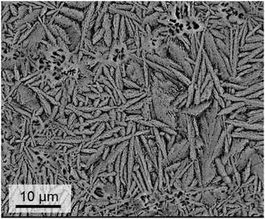 | ||
| Fig. 19 Microstructure of a sinter crystallized sample with the composition 8 BaO·8 SrO·35 ZnO·45 SiO2·1 ZrO2·1 La2O3·2 B2O3 sintered at 800 °C for 1 h. Redrawn from ref. 45. | ||
The thermal expansion is strongly affected by the grain size of the used glass powder. In general, the CTE is more negative, if the used grain size is larger. In Fig. 20, this effect is shown for sinter crystallized glass ceramics all prepared by thermal treatment at 950 °C for 1 h. The most negative CTE is obtained using the grain size fraction from 100 to 200 μm, while using the grain size fraction from 63 to 100 μm results in a material of positive CTE. Surprisingly, the CTE of some prepared materials determined by dilatometry is much more negative than that determined by high temperature XRD. This effect is due to the strong thermal expansion of the crystallographic b-axis and the contraction of the crystallographic a- and c-axis during cooling. This strongly anisotropic thermal expansion leads to stresses formed during cooling which result in microcracks. During heating, the microcracks will successively be closed while they are opened again during cooling.
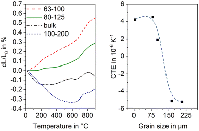 | ||
| Fig. 20 Thermal expansion of sinter crystallized glass powders with the composition 8 BaO·8 SrO·35 ZnO·45 SiO2·1 ZrO2·1 La2O3·2 B2O3 sintered at 950 °C for 1 h. Left: Dilatometric measurements. Right: CTE vs. grain size of sintered powders. The dashed line is just a guide for the eyes. Redrawn from ref. 45. | ||
6.2 Sintering of sol–gel powders
Sol–gel derived powders generally possess small crystallites with sizes in the few to some 10 nm range which hence show high sinter activity.69,70 In order to obtain Ba1−xSrxZn2Si2O7, sol–gel powders were prepared as previously described.10 After hydrolysis, polycondensation and drying, the gel was milled and subsequently thermally treated at 530 °C. Then the calcined powder was hot pressed at 1100 °C for 10 min using a uniaxial pressure of 40 MPa which resulted in almost full densification. Dilatometry showed negative thermal expansion up to a temperature of 80 °C. At higher temperatures, the CTE increases steadily. Hence, the range of negative thermal expansion is shifted to lower temperatures than in the case of a stoichiometric crystalline compound. In analogy, a BaZn2Si2O7 sample prepared via sol–gel route shows a lower phase transition temperature.7. Remarks and outlook
The low temperature phase BaZn2Si2O7 transfers to a high temperature phase at 280 °C which is accompanied by a volume increase of 3.3%. Substitution of Zn2+ against Mg2+, Mn2+, Ni2+, Co2+ or Cu2+ or of Si4+ by Ge4+ results in solid solutions and in a shift of the phase transition to higher temperatures. If Ba2+ is partially replaced against Sr2+, the phase transition temperature gets lower even below room temperature.The most remarkable property of BaZn2Si2O7 and solid solutions derived hereof are the CTEs. The low temperature phase has a high CTE in the range from 10 to 15 × 10−6 K−1, which is approximately constant up to the phase transition temperature, for the case of a 100% replacement of Zn2+ against Co2+ up to 850 °C. The CTE of the high temperature phase is small or even negative. For a substitution of 10% Ba2+ against Sr2+, a negative CTE is observed from room temperature up to a temperature of 500 °C.
The addition of network forming compounds to the stoichiometric Ba1−xSrxZnSi2O7 and/or the addition of nucleation inhibitors enables the preparation of glasses by melt quenching. Controlled crystallization of such glasses results in surface nucleation. However, the addition of nucleating agents such as ZrO2 or noble metals enables volume nucleation and the preparation of homogeneous glass ceramics. It should be mentioned that also the preparation of sintered ceramics from sol–gel derived powders with negative CTE is possible. Future developments should be focused on Ba1−xSrxZn2−yMySi2−zGezO7 crystals with smaller crystallites, i.e., a more effective homogeneous nucleation. Another important issue are glass ceramics containing Ba1−xSrxZn2−yMySi2−zGezO7 crystals of less pronounced anisotropy in the thermal expansion.
Conflicts of interest
There are no conflicts to declare.Acknowledgements
This work was funded by the German Federal Ministry of Education and Research under the Grant Numbers 03VP01701 and 03VP01702 and by the German Research Foundation (DFG) under Grant Number TH 2241/1-1.References
- J. H. Lin, G. X. Lu, J. Du, M. Z. Su, C.-K. Loong and J. W. Richardson Jr, J. Phys. Chem. Solids, 1999, 60, 975–983 CrossRef CAS.
- M. Kerstan, M. Müller and C. Rüssel, J. Solid State Chem., 2012, 188, 84–91 CrossRef CAS.
- M. Kerstan, C. Thieme, A. Kobeisy and C. Rüssel, J. Mater. Sci., 2017, 52, 1789–1796 CrossRef CAS.
- D. Ehrt, A. Herrmann and M. Tiegel, Phys. Chem. Glasses: Eur. J. Glass Sci. Technol., Part B, 2011, 52, 68–76 CAS.
- M. Kerstan, C. Thieme, M. Grosch, M. Müller and C. Rüssel, J. Solid State Chem., 2013, 207, 55–60 CrossRef CAS.
- S. S. Mitra and S. K. Joshi, J. Chem. Phys., 1961, 34, 1462–1463 CrossRef CAS.
- F. Tietz, Ionics, 1999, 5, 129–139 CrossRef CAS.
- M. K. Mahapatra and K. Lu, Mater. Sci. Eng., R, 2010, 67, 65–85 CrossRef.
- C. Thieme, H. Görls and C. Rüssel, Sci. Rep., 2015, 5, 18040 CrossRef CAS PubMed.
- M. Kracker, C. Thieme, J. Häßler and C. Rüssel, J. Eur. Ceram. Soc., 2016, 36, 2097–2107 CrossRef CAS.
- B. Li, S. Wang and Y. Fang, J. Alloys Compd., 2017, 693, 9–15 CrossRef CAS.
- J. Liu, Q. Wang, Z. Zhang, Q. Zeng, H. Peng and Q. Chang, J. Non-Cryst. Solids, 2022, 576, 121226 CrossRef CAS.
- H. Bach and D. Krause, Low Thermal Expansion Glass Ceramics, Springer, Berlin, Heidelberg, 2nd edn, 2005 Search PubMed.
- G. D. Barrera, J. A. O. Bruno, T. H. K. Barron and N. L. Allan, J. Phys.: Condens. Matter, 2005, 17, R217–R252 CrossRef CAS.
- E. D. Zanotto, Am. Ceram. Soc. Bull., 2010, 89, 19–27 CAS.
- R. M. Hovhannisyan, Glass Technol., 2003, 44, 96–100 CAS.
- J. F. MacDowell, J. Am. Ceram. Soc., 1990, 73, 2287–2292 CrossRef CAS.
- D. Tauch and C. Rüssel, J. Non-Cryst. Solids, 2005, 351, 2294–2298 CrossRef CAS.
- T. A. Mary, J. S. O. Evans, T. Vogt and A. W. Sleight, Science, 1996, 272, 90–92 CrossRef CAS.
- J. S. O. Evans, T. A. Mary, T. Vogt, M. A. Subramanian and A. W. Sleight, Chem. Mater., 1996, 8, 2809–2823 CrossRef CAS.
- R. D. Adams, R. Layland, C. Payen and T. Datta, Inorg. Chem., 1996, 35, 3492–3497 CrossRef CAS.
- C. Thieme and C. Rüssel, J. Mater. Sci., 2015, 50, 3416–3424 CrossRef CAS.
- C. Thieme, T. Waurischk, S. Heitmann and C. Rüssel, Inorg. Chem., 2016, 55, 4476–4484 CrossRef CAS PubMed.
- J. Janczak, R. Kubiak and T. Głowiak, Acta Crystallogr., Sect. C: Cryst. Struct. Commun., 1990, 46, 1383–1385 CrossRef.
- J. Ma, C. D. Dela Cruz, T. Hong, W. Tian, A. A. Aczel, S. Chi, J.-Q. Yan, Z. L. Dun, H. D. Zhou and M. Matsuda, Phys. Rev. B: Condens. Matter Mater. Phys., 2013, 88, 144405 CrossRef.
- C. Thieme and C. Rüssel, Dalton Trans., 2016, 45, 4888–4895 RSC.
- A. Erlebach, C. Thieme, C. Müller, S. Hoffmann, T. Höche, C. Rüssel and M. Sierka, Phys. Chem. Chem. Phys., 2020, 22, 18518–18525 RSC.
- A. Erlebach, G. Belhadj Hassine, C. Thieme, K. Thieme, C. Rüssel and M. Sierka, Phys. Chem. Chem. Phys., 2021, 23, 25533–25541 RSC.
- R. D. Shannon, Acta Crystallogr., Sect. A: Cryst. Phys., Diffr., Theor. Gen. Crystallogr., 1976, 32, 751–767 CrossRef.
- H. Koelmans and C. M. C. Verhagen, J. Electrochem. Soc., 1959, 106, 677–682 CrossRef CAS.
- C. Thieme and C. Rüssel, Materials, 2016, 9, 631 CrossRef PubMed.
- C. Lara, M. J. Pascual and A. Durán, J. Non-Cryst. Solids, 2004, 348, 149–155 CrossRef CAS.
- M. Imaoka and T. Yamazaki, Rep. Inst. Ind. Sci., Univ. Tokyo, 1968, 8, 241–273 Search PubMed.
- G. W. Cleek and C. L. Babcock, NBS Monogr., 1973, 135, 1–39 CAS.
- I. Avramov, R. Keding and C. Rüssel, J. Non-Cryst. Solids, 2000, 272, 147–153 CrossRef CAS.
- A. M. Hu, M. Li, D. L. M. Dali and K. M. Liang, Thermochim. Acta, 2005, 437, 110–113 CrossRef CAS.
- M. Kerstan and C. Rüssel, J. Power Sources, 2011, 196, 7578–7584 CrossRef CAS.
- M. Kerstan, M. Müller and C. Rüssel, Mater. Res. Bull., 2011, 46, 2456–2463 CrossRef CAS.
- C. Thieme, M. Schlesier, E. Oji Dike and C. Rüssel, Sci. Rep., 2017, 7, 3344 CrossRef PubMed.
- B. Tiwari, A. Dixit and G. P. Kothiyal, Int. J. Hydrogen Energy, 2011, 36, 15002–15008 CrossRef CAS.
- B. Tiwari, A. Dixit, C. G. S. Pillai, S. C. Gadkari and G. P. Kothiyal, J. Am. Ceram. Soc., 2012, 95, 1290–1296 CrossRef CAS.
- K. Thieme and C. Rüssel, J. Eur. Ceram. Soc., 2014, 34, 3969–3979 CrossRef CAS.
- K. Thieme and C. Rüssel, J. Mater. Sci., 2015, 50, 1488–1499 CrossRef CAS.
- M. Dittmer, C. F. Yamamoto, C. Bocker and C. Rüssel, Solid State Sci., 2011, 13, 2146–2153 CrossRef CAS.
- C. Thieme, M. Schlesier, C. Bocker, G. Buzatto de Souza and C. Rüssel, ACS Appl. Mater. Interfaces, 2016, 8, 20212–20219 CrossRef CAS PubMed.
- C. Thieme and C. Rüssel, Ceram. Int., 2015, 41, 13310–13319 CrossRef CAS.
- E. Kleebusch, C. Patzig, M. Krause, Y. Hu, T. Höche and C. Rüssel, Sci. Rep., 2018, 8, 2929 CrossRef PubMed.
- T. Höche, M. Mäder, S. Bhattacharyya, G. S. Henderson, T. Gemming, R. Wurth, C. Rüssel and I. Avramov, CrystEngComm, 2011, 13, 2550–2556 RSC.
- C. Patzig, T. Höche, M. Dittmer and C. Rüssel, Cryst. Growth Des., 2012, 12, 2059–2067 CrossRef CAS.
- M. Kracker, L. Vladislavova, C. Thieme, T. Zscheckel, K. Thieme, T. Höche and C. Rüssel, RSC Adv., 2017, 7, 44834–44842 RSC.
- M. Kracker, T. Zscheckel, C. Thieme, K. Thieme, T. Höche and C. Rüssel, CrystEngComm, 2019, 21, 1320–1328 RSC.
- W. Wisniewski and C. Rüssel, Prog. Mater. Sci., 2021, 118, 100758 CrossRef CAS.
- T. Waurischk, C. Thieme and C. Rüssel, J. Mater. Sci., 2020, 55, 10364–10374 CrossRef CAS.
- L. Vladislavova, C. Thieme, T. Zscheckel, C. Patzig, T. Höche and C. Rüssel, J. Eur. Ceram. Soc., 2017, 37, 4801–4808 CrossRef CAS.
- L. Vladislavova, C. Thieme, T. Zscheckel, T. Höche and C. Rüssel, J. Alloys Compd., 2019, 793, 705–714 CrossRef CAS.
- L. Vladislavova, M. Kracker, T. Zscheckel, C. Thieme and C. Rüssel, J. Mater. Sci., 2018, 53, 11204–11215 CrossRef CAS.
- M. Kracker, C. Thieme, K. Thieme, C. Patzig, L. Berthold, T. Höche and C. Rüssel, RSC Adv., 2018, 8, 6267–6277 RSC.
- C. Thieme, M. Kracker, C. Patzig, K. Thieme, C. Rüssel and T. Höche, J. Eur. Ceram. Soc., 2019, 39, 554–562 CrossRef CAS.
- M. Kracker, C. Thieme, K. Thieme, T. Höche and C. Rüssel, Ceram. Int., 2019, 45, 18760–18766 CrossRef CAS.
- C. Thieme, K. Thieme, M. Kracker, C. Patzig, L. Berthold, T. Höche and C. Rüssel, Ceram. Int., 2021, 47, 1126–1132 CrossRef CAS.
- C. Thieme, L. Vladislavova, K. Thieme, C. Patzig, T. Höche and C. Rüssel, J. Mater. Sci., 2022, 57, 6607–6618 CrossRef CAS.
- L. Vladislavova, C. Thieme and C. Rüssel, J. Mater. Sci., 2017, 52, 4052–4060 CrossRef CAS.
- L. Vladislavova, M. Kracker, T. Zscheckel, C. Thieme and C. Rüssel, Solid State Sci., 2018, 78, 107–115 CrossRef CAS.
- K. Thieme, T. Zscheckel, C. Thieme, T. Höche and C. Rüssel, J. Eur. Ceram. Soc., 2018, 38, 2017–2026 CrossRef CAS.
- K. Thieme, T. Zscheckel, C. Thieme, M. Kracker, C. Rüssel and T. Höche, Ceram. Int., 2018, 44, 19970–19980 CrossRef CAS.
- C. Thieme, A. Erlebach, C. Patzig, K. Thieme, M. Sierka, T. Höche and C. Rüssel, CrystEngComm, 2018, 20, 4565–4574 RSC.
- S. Heitmann, K. Thieme, C. Thieme, M. Kracker, T. Höche and C. Rüssel, Ceram. Int., 2019, 45, 7580–7587 CrossRef CAS.
- C. Thieme, J. Am. Ceram. Soc., 2021, 105, 3544–3554 CrossRef.
- C. J. Brinker and G. W. Scherer, Sol-gel science: the physics and chemistry of sol-gel processing, Academic Press, Boston, 1990 Search PubMed.
- S. Sakka, Handbook of sol-gel science and technology: processing, characterization, and applications, Kluwer Academic Publishers, Boston, 2005, vol. 3 Search PubMed.
| This journal is © The Royal Society of Chemistry 2022 |

