Preparation of ZIF-8-coated silica hard-shell microcapsule by semi-batch operation†
Shuei
Kawada
a,
Takumu
Otsubo
a,
Takafumi
Horie
b,
Yoshiyuki
Komoda
 ac,
Naoto
Ohmura
ac,
Hitoshi
Asano
cd,
Ruri
Hidema
ac,
Naoto
Ohmura
ac,
Hitoshi
Asano
cd,
Ruri
Hidema
 ac,
Hiroshi
Suzuki
 ac,
Keita
Taniya
 *ac,
Yuichi
Ichihashi
ac and
Satoru
Nishiyama
ac
aDepartment of Chemical Science and Engineering, Kobe University, 1-1 Rokkodai-cho, Nada-ku, Kobe, Hyogo 657-8501, Japan. E-mail: taniya@platinum.kobe-u.ac.jp
bDepartment of Chemical Engineering, Osaka Metropolitan University, 1-1 Gakuen-cho, Naka-ku, Sakai, Osaka 599-8531, Japan
cComplex Fluid and Thermal Engineering Research Center (COFTEC), Kobe University, 1-1 Rokkodai-cho, Nada-ku, Kobe, Hyogo 657-8501, Japan
dDepartment of Mechanical Engineering, Kobe University, 1-1 Rokkodai-cho, Nada-ku, Kobe, Hyogo 657-8501, Japan
First published on 15th September 2022
Abstract
This paper reports the selective fabrication of a zeolitic imidazolate framework-8 (ZIF-8) cover layer over the outer surface of silica hard-shell microcapsules (HSMC) to improve the microencapsulation technique of phase change materials for heat storage materials. ZIF-8 was formed not only over the HSMC but also in the synthesis solution side when using a conventional batch operation owing to the rapid formation rate of ZIF-8 in the aqueous solution at 293 K. In this study, a semi-batch operation, which can control the concentration of the components in the synthesis solution by gradually dropping the components, was employed to decrease the formation rate of ZIF-8. X-ray diffraction results suggested that dropping ingredients strongly affected the obtained products; the addition of the Zn2+ aqueous solution into a 2-methylimidazole (Hmim) aqueous solution was suitable for the formation of ZIF-8, whereas the addition of an aqueous solution of Hmim into the Zn2+ aqueous solution formed Zn hydroxides as unfavorable by-products. Field-emission scanning electron microscopy and energy-dispersive X-ray spectroscopy results confirmed that the semi-batch operation with the addition of Zn2+ into the Hmim aqueous solution selectively formed a ZIF-8 cover layer over the HSMC. We conclude that the semi-batch operation is an effective procedure for suppressing the unfavorable homogeneous nucleation on the solution side and making heterogeneous nucleation dominant without any additives to fabricate the ZIF-8 cover layer.
Introduction
Porous hollow silica particles, which comprise an inner hollow cavity and a porous SiO2 shell, have received considerable attention in various fields, including catalysis, drug delivery, sensors, functional coatings, thermal insulation, and energy storage.1–3 In the field of energy storage, porous hollow silica particles are expected to be applied to the encapsulation of phase change materials (PCMs) for latent heat storage systems.4–11 Notably, although the thermal conductivity of silica is low, microencapsulation can lower its thermal resistance (details are provided in section 1 of ESI†) and increase its surface area, resulting in better thermophysical properties. In principle, organic and inorganic PCMs can be filled into the hollow space of the hard-shell microcapsule (HSMC) through the pores in the SiO2 shell. The pores in the SiO2 shell cause the charged PCMs to leak from the hollow cavity during their utilization in the latent heat transportation system. Therefore, the pores in the SiO2 shell must be covered with nonporous or porous materials with a pore diameter smaller than those of PCMs to prevent the leakage of PCMs from the HSMC.When paraffin, a common organic PCM, is filled into the hollow space of HSMCs for use at 60–100 °C, which is currently not effectively utilized, the following synthesis conditions are required during the fabrication of a covering layer. First, the synthesis temperature must be lower than the melting point of PCMs to prevent them from leaking out due to melting. Second, solvents that cannot easily dissolve PCMs must be selected to prevent leakage due to dissolution. Third, heat treatment at high temperatures to synthesize the covering layers must be avoided to prevent PCMs from decomposition and/or combustion.
Shell materials used for direct microencapsulation of PCMs by emulsion methods are considered to be ideal candidates for cover layer materials for HSMCs. Previously, SiO2 and TiO2 have been used as inorganic shell materials owing to their high mechanical stability and thermal conductivity.12 SiO2 has been widely investigated and can be easily prepared by the Stöber process via hydrolysis and condensation of tetraethyl orthosilicate (TEOS).13 However, the sol–gel process using TEOS is generally performed in a mixed solution of alcohols and water.13 Therefore, there is a risk of paraffin leakage due to dissolution by alcohols during the synthesis process.
Acrylic and melamine resins have been reported to be used as organic shell materials.12 They have good structural flexibility but less mechanical stability and thermal conductivity when compared with those of inorganic shell materials. Because polymethyl methacrylate (PMMA), which is an acrylic resin, was reported to be synthesized at around 318–363 K,14 paraffin will presumably leak from HSMC during the PMMA cover layer synthesis owing to the melting of paraffin. Therefore, the synthesis of cover layers while maintaining the PCMs within the HSMCs is a challenging task.
Zeolitic imidazolate frameworks (ZIFs) with a sodalite structure, a subclass of metal organic frameworks (MOFs), are promising materials that can satisfy the aforementioned requirements. ZIF-8, -67, and -90 are composed of zinc cation and 2-methylimidazole (Hmim) linker, cobalt cation and Hmim linker, and zinc cation and 2-formylimidazole, respectively. These have been widely investigated for various applications such as catalysis,15 gas separation,16 enzyme immobilization,17,18 and heat storage.19 These ZIFs can be synthesized in an aqueous solution.20–26 Furthermore, synthesizing these ZIFs in water solvent is advantageous because ZIF synthesis can proceed at approximately 293 K and no high-temperature heat treatment is required.
Among them, ZIF-8, which has large cages (11.6 Å in diameter) and small apertures (3.4 Å),27 has also been extensively investigated as a material for membranes.16,28 The ZIF-8 membrane was reported to selectively separate propylene from the gas mixture of propylene and propane.28 The leakage of PCMs, whose size is larger than that of propane, is expected to be suppressed using ZIF-8 as the cover layer.
Because the thermal conductivity29 and mechanical stability30 of ZIF-8 are reported to be comparable to those of organic materials such as PMMA, ZIF-8 is a promising material as a cover layer. It has high potential for preventing paraffin leakage caused by dissolution, melting, and decomposition during the ZIF-8 synthesis at approximately 293 K in water solvent. Therefore, ZIF-8 is selected as the cover layer of HSMC containing PCMs in this study.
Some efforts have been made to synthesize a ZIF-8 cover layer on the outer surface of a silica sphere31–38 for high-performance liquid chromatography,32,33 pervaporation,34 and drug delivery,35 among others.36–38 Homogeneous nucleation dominantly proceeds because the ZIF-8 formation rate is markedly fast in aqueous solution;39–42 this is unfavorable for the synthesis of the cover layer. Sorribas et al. reported the fabrication of a mesoporous silica sphere–(ZIF-8) core–shell composite at room temperature,38 wherein the in situ deposition of ZIF-8 seeds over silica spheres and the crystal growth of deposited ZIF-8 were realized in two different solutions—an aqueous solution and a mixed solution of water and methanol, respectively—to predominantly promote heterogeneous nucleation and crystal growth. Peng et al. reported that a very thin ZIF-8 layer was constructed over the silica nanospheres by immersing them alternately in Zn2+ methanol and Hmim methanol solutions.36 They also reported that the thickness of the ZIF-8 layer was controlled in the nano-order by varying the immersion cycles. In this way, multistep coating processes using methanol solutions have been applied to successfully fabricate ZIF-8 layers on the silica spheres. However, the increased number of coating steps and the incorporation of additives, such as methanol, increase the risk of PCM leakage during the multistep coating process. In addition, methanol, which is used as an inhibitor of ZIF-8 formation to effectively promote crystal growth, is a toxic organic solvent. Therefore, a simpler procedure is needed for controlling the ZIF-8 formation in aqueous systems at relatively low temperatures and without additives to selectively fabricate a ZIF-8 layer over the outer surface of the HSMC. This study proposes a simple procedure to control the ZIF-8 nucleation rate in aqueous systems, which will enable a more precise control of the morphology of ZIF-8 layers over various supports.
We report the synthesis of ZIF-8-coated SiO2 hard-shell microcapsules (ZIF-8/HSMCs) in an aqueous system at 293 K. Two different operations (batch and semi-batch operations) were investigated to fabricate the ZIF-8 cover layer on the outer surface of the HSMC. In the semi-batch operation, one component used to construct ZIF-8 can be periodically supplied to the other. Heterogeneous nucleation and crystal growth are expected to dominate by controlling the concentration of the components of ZIF-8 in an aqueous solution and by suppressing the ZIF-8 formation rate. Further, the importance of the dropping component in the semi-batch operation to ZIF-8 is discussed. Improving the control technique for the ZIF-8 formation rate without any organic solvents and additives can provide process intensification for preparing ZIF-8 cover layers and membranes.
Experimental
Materials
For the synthesis of HSMCs, sodium silicate solution (52–57%), ammonium hydrogen carbonate, and hexane were purchased from FUJIFILM Wako Pure Chemical Corporation; sodium polymethacrylate was obtained from Sigma-Aldrich Japan; and polyoxyethylene sorbitan monooleate (Tween80) and sorbitan monooleate (Span80) were purchased from Tokyo Chemical Industry Co., Ltd.Hydrochloric acid (0.1 mol L−1) and 3-(2-imidazolin-1-yl)propyltriethoxysilane (IPTES) were purchased from Nacalai Tesque Inc. and Sigma-Aldrich Japan, respectively, for the IPTES modification on the surface of the HSMC.
For the fabrication of the ZIF-8 cover layer, zinc nitrate hexahydrate and 2-methylimidazole (Hmim) were supplied from Nacalai Tesque Inc. and Tokyo Chemical Industry Co., Ltd., respectively. All purchased chemicals were used without any other purification.
Preparation of silica hard-shell microcapsules (HSMC)
Silica hard-shell microcapsules (HSMC) are synthesized using a double-emulsion system. The synthesis procedures for HSMC have been described in detail in previous papers.7,10,11Synthesis of ZIF-8-coated silica hard-shell microcapsules (ZIF-8/HSMC)
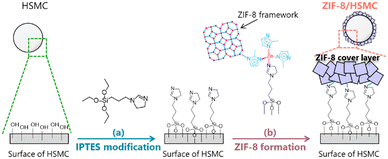
The synthesis of ZIF-8/HSMC was conducted in two steps (Scheme 1): IPTES was modified on the surface of HSMC in the first step (Scheme 1a), followed by ZIF-8 coating over the IPTES–HSMC as second step (Scheme 1b).This study focused on developing a synthesis process for the ZIF-8 cover layer over HSMC. Therefore, in this study, no PCM was charged in the HSMC.
Synthesis of ZIF-8-coated silica hard-shell microcapsules (ZIF-8/HSMC)
The coating of ZIF-8 over the IPTES–HSMC was performed by two different operations, i.e., a batch operation and a semi-batch operation, which were conducted in the aqueous solution at 293 K. With respect to the semi-batch operation, the influence of the dropping solutions on ZIF-8 formation was investigated.Characterization
X-ray diffraction (XRD) patterns of each ZIF-8/HSMCs were acquired using a Rigaku MiniFlex600-C apparatus equipped with a Cu-Kα radiation source operating at 40 kV and 15 mA. The theoretical XRD pattern of ZIF-8 was simulated by VESTA44 based on COD No. 4118891. Field-emission scanning electron microscopy (FE-SEM) images of each ZIF-8/HSMCs were obtained using a JEOL JSM-7500F instrument operated at 5 kV. Energy-dispersive X-ray spectroscopy (EDS) spectra for elemental mapping were acquired using a JEOL EX-64195 JMU installed in the same SEM instrument. Nitrogen adsorption isotherms were recorded at 77 K using a MicrotracBEL BELSOPR-mini instrument after pretreatment at 473 K under a flow of N2 at 50 mL min−1. The specific surface area was evaluated from the N2 adsorption data using the Brunauer–Emmett–Teller (BET) method. Thermogravimetric and differential thermal analysis (TG-DTA) was conducted on a Rigaku Thermo plus EVO2 TG 8121 over a temperature range between room temperature and 973 K at a heating rate of 5 K min−1 in a flow of a mixture of O2 and N2 (O2![[thin space (1/6-em)]](https://www.rsc.org/images/entities/char_2009.gif) :
:![[thin space (1/6-em)]](https://www.rsc.org/images/entities/char_2009.gif) N2 = 1
N2 = 1![[thin space (1/6-em)]](https://www.rsc.org/images/entities/char_2009.gif) :
:![[thin space (1/6-em)]](https://www.rsc.org/images/entities/char_2009.gif) 4, total flow rate = 125 mL min−1).
4, total flow rate = 125 mL min−1).
Results and discussion
IPTES modification of HSMCs
The formation of active species on the surface of materials by the immobilization of organosilanes is an effective technique for heterogeneous nucleation and crystal growth. For instance, the modification of 3-aminopropyltriethoxyxilane (APTES)45,46 and 3-(2-imidazolin-1-yl)propyltriethoxysilane (IPTES)36,40,43 on the surface of supports has been reported to promote the formation of dense ZIF-8 membranes. In this study, IPTES was employed as a surface modifier for the selective formation of a ZIF-8 cover layer over the outer surface of HSMCs. Fig. 1 shows the amount of IPTES modified on the HSMCs prepared by varying the IPTES concentrations. The detailed procedure for evaluating the modified amount of IPTES is described in section 2 of ESI.†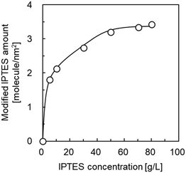 | ||
| Fig. 1 Influence of IPTES concentration in the starting mixture on the amount of IPTES modified in the HSMC. | ||
The modified amount of IPTES increased with increasing IPTES concentration up to 70 g L−1; it was maintained at a constant 3.3 molecule per nm2 at an IPTES concentration greater than 70 g L−1. These results suggest that the number of IPTES molecules modified on the surface of the HSMCs is saturated on IPTES–HSMCs obtained at IPTES concentrations greater than 70 g L−1. Therefore, IPTES–HSMC prepared at an IPTES concentration of 70 g L−1 was used for the synthesis of the ZIF-8 cover layers in the following study.
Characteristics of ZIF-8-coated HSMC prepared by batch operation (ZIF-8/HSMC-B)
ZIF-8-coated HSMC (ZIF-8/HSMC-B) was prepared in water at 293 K using conventional batch operation. Fig. 2 shows the XRD patterns of the HSMC, simulated ZIF-8, and ZIF-8/HSMC-B. A broad peak at 2θ = 23° attributed to amorphous silica in the HSMCs is observed (Fig. 2a). For ZIF-8/HSMC-B (Fig. 2c), the peaks observed at 2θ = 7.4°, 10.4°, 12.7°, 14.7°, 16.4°, 18.0°, 22.1°, 24.5°, 26.7°, and 29.6° coincided with the simulated patterns of ZIF-8 obtained from crystal structure data (COD No. 4118891), which indicates that the ZIF-8 crystalline structure is formed during batch operation.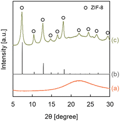 | ||
| Fig. 2 XRD patterns of (a) the original HSMC, (b) simulated ZIF-8, and (c) ZIF-8/HSMC-B prepared via batch operation. | ||
Fig. 3 shows the SEM images of HSMC and ZIF-8/HSMC-B. In the HSMC (Fig. 3a) prepared according to previous reports,7,10,11 microspheres with a diameter of approximately 7 μm were observed. Black spots of approximately 100 nm were observed on the surface of the HSMC, and they were attributed to the pore mouth in the SiO2 shell, which can connect the outer surface to the inner hollow cavity in the HSMC. For ZIF-8/HSMC-B (Fig. 3b), significant changes in the surface morphology of HSMC are hardly observed, whereas polyhedral crystals clearly appear around the HSMC particles; they are not observed in the original HSMC (Fig. 3a). A variety of ZIF-8 shapes have been reported depending on the progress of crystal growth.23,47 Cravillon et al. reported that the ZIF-8 morphology transformed from cubic to rhombic dodecahedron as the crystal grew over time during the preparation by the solvothermal method using the formate as a modulator.47 Polyhedral crystals observed in Fig. 3b are suspected to be ZIF-8 crystals. The low-magnitude SEM image and SEM-EDS maps of ZIF-8/HSMC-B are shown in Fig. 3c and d, respectively. Zinc species, one of the components of ZIF-8, are found to be located not only in the polyhedral crystals but also on the surface of the HSMC (Fig. 3c). These results suggest that ZIF-8 may be precipitated on the HSMC; however, the nucleation of ZIF-8 also occurs in the solution during the preparation by batch operation. The selective formation of the ZIF-8 cover layer on the HSMC was unsuccessful using conventional batch operation.
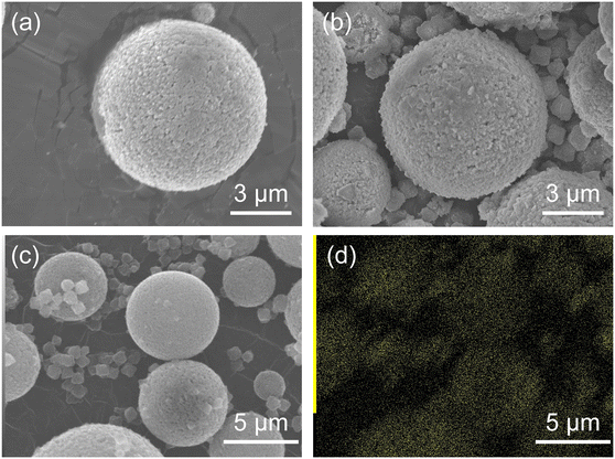 | ||
| Fig. 3 (a) High-magnitude SEM images of original HSMC and (b) ZIF-8/HSMC-B prepared via batch operation, (c) low-magnitude SEM image, and (d) EDS mapping of Zn for ZIF-8/HSMC-B. | ||
With respect to the batch operation, the formation of ZIF-8 crystals around the HSMC was probably attributed to the rapid nucleation of ZIF-8 on the synthesis solution side. Tanaka et al. reported that a cloudy colloidal suspension of ZIF-8 can be obtained in only 10 s when using Zn(NO3)2·6H2O as a zinc resource in an aqueous solution at room temperature.40 The ZIF-8 formation by batch operation is conducted under similar conditions, i.e., in a water solvent using zinc nitrate. In the batch operation, the concentrations of both components increased in the synthesis solution immediately after mixing the Zn aqueous solution with the Hmim aqueous solution. The high concentration of Zn2+ and Hmim in the solution is suggested to increase the ZIF-8 formation rate and dominantly promote the homogeneous nucleation of ZIF-8 in the synthesis solution side (Scheme 2).
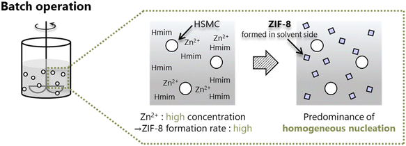 | ||
| Scheme 2 Formation of ZIF-8 crystals through predominant homogeneous nucleation in the synthesis solution side during batch operation. | ||
Fabrication of ZIF-8/HSMC by semi-batch operation and their characteristics
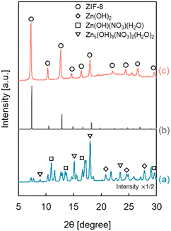
Heterogeneous nucleation occurs preferentially at low supersaturation compared with homogeneous nucleation. It is essential to maintain a low precursor concentration and suppress the formation rate of ZIF-8 to selectively form a ZIF-8 cover layer on the outer surface of the HSMC at low supersaturation. Therefore, we focus on a semi-batch operation to control the formation rate by suppressing the precursor concentration in the preparation mixture to synthesize ZIF-8 over HSMC selectively.Since ZIF-8 is composed of two ingredients, Zn2+ and Hmim, and there are two ways to add these materials: one is to drop the Zn2+ aqueous solution into the Hmim aqueous solution, and the other is to drop the Hmim aqueous solution into the Zn2+ aqueous solution. Fig. 4 shows the XRD patterns of ZIF-8/HSMC prepared by the semi-batch operation (ZIF-8/HSMC-SB) with the two different ways of adding the ingredients. In the case of ZIF-8/HSMC-SBHmim, which was prepared by dropping the Hmim aqueous solution into the Zn2+ aqueous solution, several peaks were observed, but none corresponded to ZIF-8 (Fig. 4a). The observed peaks indicate the formation of Zn(OH)2, Zn(OH)(NO3)·H2O, and Zn5(OH)8(NO3)2·2H2O.24 In contrast, the peaks corresponding to crystalline ZIF-8 clearly appeared in the case of ZIF-8/HSMC-SBZn, which was prepared by dropping the Zn2+ aqueous solution into the Hmim aqueous solution (Fig. 4c), indicating that the ZIF-8 crystalline structure was formed during the preparation process. These results clearly suggest that the dropping ingredient strongly affects the formation of ZIF-8 in the semi-batch operation.
In water, both mim− generated by the deprotonation of Hmim and OH− competitively coordinated to Zn2+, which results in the generation of ZIF-8 and zinc hydroxides, respectively. Therefore, an excess amount of Hmim compared to Zn2+ is required to suppress the formation of zinc hydroxides as by-products for the aqueous system to synthesize ZIF-8.23,24,40,48,49
Tanaka et al. reported that a Hmim/Zn molar ratio greater than 40 is necessary to obtain highly pure ZIF-8 without any by-products using Zn(NO3)2 as a zinc precursor in the water solvent.24 In semi-batch operation, the Hmim/Zn molar ratio in the preparation mixture for ZIF-8 varied with the elapsed time. Fig. S2† shows the calculated change in the Hmim/Zn molar ratio in the semi-batch operation as a function of the dropping time. The Hmim/Zn molar ratio was always less than 30 when Hmim was added to the Zn2+ aqueous solution (Fig. S2a†), which brings about the preferential coordination of OH− to Zn2+ to form the unfavorable zinc hydroxides.24 Hmim/Zn molar ratio was always higher than 30 by dropping Zn2+ in to Hmim aqueous solution (Fig. S2b†). In this case, the presence of sufficient free mim− around the added Zn2+ promoted the favorable Zn2+–mim− coordination, which results in the preferential ZIF-8 formation. In the aqueous synthesis of ZIF-8 using a semi-batch operation, the dropped ingredient species is suggested to play an important role in regulating the coordination species to Zn2+ to suppress the formation of by-products such as Zn hydroxides.
The morphology of ZIF-8-coated HSMCs prepared by semi-batch operations with different dropping ingredients was investigated by SEM, as shown in Fig. 5. For ZIF-8/HSMC-SBHmim, grains with several different shapes such as plates, rods, and needles were observed (Fig. 5a). Watanabe et al. reported that rod-shaped particles were obtained as by-products during the ZIF-8 preparation using a microreactor in an aqueous solution at Hmim/Zn = 20.49 Therefore, these grains are attributed to the formation of zinc hydroxides, which was confirmed by XRD measurements (Fig. 4a).
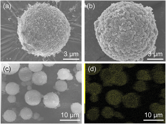 | ||
| Fig. 5 (a) High-magnitude SEM images of ZIF-8/HSMC-SBHmim and (b) ZIF-8/HSMC-SBZn, (c) low-magnitude SEM image, and (d) EDS mapping of Zn for ZIF-8/HSMC-SBZn. | ||
For the ZIF-8/HSMC-SBZn prepared by dropping the Zn2+ aqueous solution into Hmim aqueous solution, the apertures of the original HSMC disappeared and an uneven surface appeared (Fig. 5b). These uneven surfaces comprised grains with a diameter of approximately 600 nm, which were connected to each other. A low-magnification SEM image and elemental mapping of Zn by SEM-EDS measurements are shown in Fig. 5c and d, respectively. Zinc species were found to be selectively present in HSMCs. The XRD (Fig. 4c) and SEM-EDS (Fig. 5b–d) results clearly reveal that grains comprising ZIF-8 formed over the outer surface of the HSMC. A semi-batch operation is a good method to control the reactant concentration in the preparation mixture because one ingredient is gradually supplied to the others. Scheme 3 illustrates the formation of the ZIF-8 cover layer using a semi-batch process. Semi-batch operation by the gradual addition of Zn2+ can maintain low concentration in the preparation mixture to form ZIF-8, which can decrease the formation rate of ZIF-8 and inhibit the homogeneous nucleation of ZIF-8 on the solution side. Heterogeneous nucleation and crystal growth became dominant by suppressing homogeneous nucleation, which results in the selective formation of a ZIF-8 cover layer on the outer surface of the HSMCs. Therefore, the control of the ZIF-8 formation rate by semi-batch operation is extremely effective for the selective ZIF-8 formation over the outer surface of the HSMC.
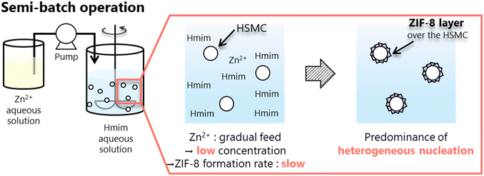 | ||
| Scheme 3 Selective formation of ZIF-8 cover layer over HSMC surface through predominant heterogeneous nucleation and crystal growth using semi-batch operation. | ||
Conclusions
The preparation of ZIF-8/HSMCs in an aqueous system at 293 K was investigated. The HSMCs surface was modified with IPTES to facilitate the heterogeneous nucleation and crystal growth of ZIF-8; the amount of IPTES modified over the HSMCs was varied by controlling the initial concentration of IPTES during the modification process. The ZIF-8 layer hardly formed over the outer surface of the HSMCs when using the conventional batch operation because ZIF-8 crystals precipitated in the solution side by unfavorable homogeneous nucleation. The type of ingredients fed in a semi-batch operation were found to be key factors in obtaining ZIF-8, which feeds the Zn2+ aqueous solution into the Hmim aqueous solution produced ZIF-8, whereas adding the Hmim aqueous solution into the Zn2+ aqueous solution resulted in the generation of several types of zinc hydroxides. ZIF-8/HSMC-SBZn, prepared by semi-batch operation feeding Zn2+ to the Hmim solution, and ZIF-8 crystals were selectively deposited over the outer surface of HSMCs; this leads to the successful fabrication of the ZIF-8 cover layer.This semi-batch operation introduces the option of making the heterogeneous nucleation and crystal growth dominant. This can contribute to reducing the amount of additives (such as modulators and/or organic solvents) needed to fabricate a uniform and dense cover layer of ZIF-8. Additionally, our findings clearly suggest that the order and supplying rate in which the ingredients are fed strongly affect the formation of ZIF-8, and can help suppress the homogeneous nucleation and generation of byproducts. This can improve the productivity on a large-scale and enable the formation of ZIF-8, not only over the surface of fine particles, but also over various supports for membranes.
In the semi-batch operation, a threshold for the dropping rate at which the homogeneous nucleation becomes dominant is likely to exist. Although it was not quantitatively estimated in this study, the evaluation of this limitation would help us find an operation range in which heterogeneous nucleation can be maintained to form a uniform cover layer. The threshold for the dropping rate is presumably affected by the synthesis conditions, such as the concentration of the ingredients, Hmim/Zn molar ratio, Zn precursors, temperature, and pH. Further studies for evaluating this threshold are thus required.
The stability of the ZIF-8 layer, an important factor for using ZIF-8/HSMCs, was not evaluated in this study. The ZIF-8 structure is reported to be intact for 2 months in water at room temperature50 and 7 d in water at 100 °C,51 but is easily dissolved in HCl aqueous solution (pH = 0).50 The ZIF-8/HSMCs will be used in water containing a trace amount of surfactant and polyvinyl alcohol to assist in the dispersion of the microcapsules in latent heat transport systems. Further studies for estimating the stability of ZIF-8 layer are required under the optimized operating condition of microcapsules.
Author contributions
Shuei Kawada: investigation, writing – original draft. Takumu Otsubo: investigation, validation. Takafumi Horie: methodology, resources. Yoshiyuki Komoda: methodology. Naoto Ohmura: resources. Hitoshi Asano: resources. Ruri Hidema: data curation. Hiroshi Suzuki: project administration, funding acquisition. Keita Taniya: investigation, conceptualization, writing – original draft, writing – review & editing, supervision. Yuichi Ichihashi: methodology. Satoru Nishiyama: writing – review & editing, supervision.Conflicts of interest
There are no conflicts to declare.Acknowledgements
This study was supported by the JST-Mirai project (grant number JPMJMI17EK). We wish to acknowledge Dr. Yu Horiuchi, Associate Professor of Osaka Metropolitan University, for his help in preparing the simulated XRD pattern of ZIF-8. We would like to thank Editage (https://www.editage.com) for English language editing.References
- M. Fuji, C. Takai and R. V. Rivera Virtudazo, Adv. Powder Technol., 2014, 25, 91–100 CrossRef CAS.
- M. Fuji, J. Ceram. Soc. Jpn., 2015, 123, 835–844 CrossRef CAS.
- J. Sharma and G. Polizos, Nanomaterials, 2020, 10, 1599 CrossRef CAS PubMed.
- E. M. Shchukina, M. Graham, Z. Zheng and D. G. Shchukin, Chem. Soc. Rev., 2018, 47, 4156–4175 RSC.
- W. Aftab, X. Huang, W. Wu, Z. Liang, A. Mahmood and R. Zou, Energy Environ. Sci., 2018, 11, 1392–1424 RSC.
- R.-A. Lincu, S. Ioniţa, D. Lincu, D. Berger and C. Matei, Molecules, 2021, 26, 241 CrossRef PubMed.
- R. V. R. Virtudazo, M. Fuji and T. Shirai, Mater. Lett., 2011, 65, 3112–3115 CrossRef CAS.
- R. V. Rivera Virtudazo, R. T. Wu, S. Zhao and M. M. Koebel, Mater. Lett., 2014, 126, 92–96 CrossRef CAS.
- M. A. Ashraf, A. M. Khan, M. Ahmad and M. Sarfraz, Front. Chem., 2015, 3, 42 Search PubMed.
- T. Toyoda, R. Narisada, H. Suzuki, R. Hidema and Y. Komoda, Chem. Lett., 2014, 43, 820–821 CrossRef CAS.
- M. Tamaru, H. Suzuki, R. Hidema, Y. Komoda and K. Suzuki, Int. J. Refrig., 2017, 82, 97–105 CrossRef CAS.
- G. Peng, G. Dou, Y. Hu, Y. Sun and Z. Chen, Adv. Polym. Technol., 2020, 2020, 9490873 CrossRef.
- W. Stober, A. Fink and E. Bohn, J. Colloid Interface Sci., 1968, 26, 62–69 CrossRef.
- D. Xu and R. Yang, J. Appl. Polym. Sci., 2019, 136, 47552 CrossRef.
- H. Konnerth, B. M. Matsagar, S. S. Chen, M. H. G. Prechtl, F.-K. Shieh and K. C. W. Wu, Coord. Chem. Rev., 2020, 416, 213319 CrossRef CAS.
- M. Bergaoui, M. Khalfaoui, A. Awadallah-F and S. Al-Muhtaseb, J. Nat. Gas Sci. Eng., 2021, 96, 104289 CrossRef CAS.
- S.-Y. Chen, W.-S. Lo, Y.-D. Huang, X. Si, F.-S. Liao, S.-W. Lin, B. P. Williams, T.-Q. Sun, H.-W. Lin, Y. An, T. Sun, Y. Ma, H.-C. Yang, L.-Y. Chou, F.-K. Shieh and S.-K. Tsung, Nano Lett., 2020, 20, 6630–6635 CrossRef CAS PubMed.
- W. Liang, F. Carraro, M. B. Solomon, S. G. Bell, H. Amenitsch, C. J. Sumby, N. G. White, P. Falcaro and C. J. Doonan, J. Am. Chem. Soc., 2019, 141, 14298–14305 CrossRef CAS.
- C. Byrne, A. Ristić, S. Mal, M. Opresnik and N. Zabukovec Logar, Crystals, 2021, 11, 1142 CrossRef.
- Y. Pan, D. Heryadi, F. Zhou, L. Zhao, G. Lestari, H. Su and Z. Lai, CrystEngComm, 2011, 13, 6937–6940 RSC.
- Y. Pan, Y. Liu, G. Zeng, L. Zhao and Z. Lai, Chem. Commun., 2011, 47, 2071–2073 RSC.
- S. Tanaka, K. Kida, M. Okita, Y. Ito and Y. Miyake, Chem. Lett., 2012, 41, 1337–1339 CrossRef CAS.
- M. Jian, B. Liu, R. Liu, J. Qu, H. Wang and X. Zhang, RSC Adv., 2015, 5, 48433–48441 RSC.
- K. Kida, M. Okita, K. Fujita, S. Tanaka and Y. Miyake, CrystEngComm, 2013, 15, 1794–1801 RSC.
- R. R. Kuruppathparambil, T. Jose, R. Babu, G.-Y. Hwang, A. C. Kathalikkattil, D.-W. Kim and D.-W. Park, Appl. Catal., B, 2016, 182, 562–569 CrossRef CAS.
- F.-K. Shieh, S.-C. Wang, S.-Y. Leo and K. C. W. Wu, Chem. – Eur. J., 2013, 19, 11139–11142 CrossRef CAS.
- R. Wu, T. Fan, J. Chen and Y. Li, ACS Sustainable Chem. Eng., 2019, 7, 3632–3646 CrossRef CAS.
- M. Guo and M. Kanezashi, Membranes, 2021, 11, 310 CrossRef CAS PubMed.
- M. J. Assael, S. Botsios, K. Gialou and N. Metaxa, Int. J. Thermophys., 2005, 26, 1595–1605 CrossRef CAS.
- J. C. Tan, T. D. Bennett and A. K. Cheetham, Proc. Natl. Acad. Sci. U. S. A., 2010, 107, 9938–9943 CrossRef CAS PubMed.
- N. Yuan, X. Zhang and L. Wang, Coord. Chem. Rev., 2020, 421, 213442 CrossRef CAS.
- Q. Wei, C. Lian, H. Su, D. Gao and S. Wang, Microporous Mesoporous Mater., 2019, 288, 109574 CrossRef CAS.
- Y. Y. Fu, C. X. Yang and X. P. Yan, Chemistry, 2013, 19, 13484–13491 CrossRef CAS.
- Y. C. Sue, J. W. Wu, S. E. Chung, C. H. Kang, K. L. Tung, K. C. W. Wu and F. K. Shieh, ACS Appl. Mater. Interfaces, 2014, 6, 5192–5198 CrossRef CAS PubMed.
- X. Jia, Z. Yang, Y. Wang, Y. Chen, H. Yuan, H. Chen, X. Xu, X. Gao, Z. Liang, Y. Sun, J. R. Li, H. Zheng and R. Cao, ChemMedChem, 2018, 13, 400–405 CrossRef CAS PubMed.
- J. Peng, X. Sun, Y. Li, C. Huang, J. Jin, J. W. Dhanjai, J. Wang and J. Chen, Microporous Mesoporous Mater., 2018, 268, 268–275 CrossRef CAS.
- B. Xi, Y. C. Tan and H. C. Zeng, Chem. Mater., 2016, 28, 326–336 CrossRef CAS.
- S. Sorribas, B. Zornoza, C. Téllez and J. Coronas, Chem. Commun., 2012, 48, 9388–9390 RSC.
- K. Kida, K. Fujita, T. Shimada, S. Tanaka and Y. Miyake, Dalton Trans., 2013, 42, 11128–11135 RSC.
- S. Tanaka, T. Shimada, K. Fujita, Y. Miyake, K. Kida, K. Yogo, J. F. M. Denayer, M. Sugita and T. Takewaki, J. Membr. Sci., 2014, 472, 29–38 CrossRef CAS.
- Y. Pan and Z. Lai, Chem. Commun., 2011, 47, 10275–10277 RSC.
- J. Yao, L. Li, W. H. B. Benjamin Wong, C. Tan, D. Dong and H. Wang, Mater. Chem. Phys., 2013, 139, 1003–1008 CrossRef CAS.
- S. Tanaka, K. Okubo, K. Kida, M. Sugita and T. Takewaki, J. Membr. Sci., 2017, 544, 306–311 CrossRef CAS.
- K. Momma and F. Izumi, J. Appl. Crystallogr., 2011, 44, 1272–1276 CrossRef CAS.
- Z. Xie, J. Yang, J. Wang, J. Bai, H. Yin, B. Yuan, J. Lu, Y. Zhang, L. Zhou and C. Duan, Chem. Commun., 2012, 48, 5977–5979 RSC.
- K. Huang, Z. Dong, Q. Li and W. Jin, Chem. Commun., 2013, 49, 10326–10328 RSC.
- J. Cravillon, C. A. Schröder, H. Bux, A. Rothkirch, J. Caro and M. Wiebcke, CrystEngComm, 2012, 14, 492–498 RSC.
- S. Watanabe, S. Ohsaki, T. Hanafusa, K. Takada, H. Tanaka, K. Mae and M. T. Miyahara, Chem. Eng. J., 2017, 313, 724–733 CrossRef CAS.
- S. Watanabe, S. Ohsaki, A. Fukuta, T. Hanafusa, K. Takada, H. Tanaka, T. Maki, K. Mae and M. T. Miyahara, Adv. Powder Technol., 2017, 28, 3104–3110 CrossRef CAS.
- K. Leus, T. Bogaerts, J. D. Decker, H. Depauw, K. Hendrickx, H. Vrielinck, V. V. Speybroeck and P. V. D. Voort, Microporous Mesoporous Mater., 2016, 226, 110–116 CrossRef CAS.
- K. S. Park, Z. Ni, A. P. Côté, J. Y. Choi, R. Huang, F. J. Uribe-Romo, H. K. Chae, M. O'Keeffe and O. M. Yaghi, Proc. Natl. Acad. Sci. U. S. A., 2006, 103, 10186–10191 CrossRef CAS.
Footnote |
| † Electronic supplementary information (ESI) available. See DOI: https://doi.org/10.1039/d2ce00488g |
| This journal is © The Royal Society of Chemistry 2022 |

