A materials perspective on magnesium-ion-based solid-state electrolytes
Prem Wicram
Jaschin
 a,
Yirong
Gao
a,
Yao
Li
*b and
Shou-Hang
Bo
a,
Yirong
Gao
a,
Yao
Li
*b and
Shou-Hang
Bo
 *a
*a
aUniversity of Michigan-Shanghai Jiao Tong University Joint Institute, Shanghai Jiao Tong University, 800 Dong Chuan Road, Minhang District, Shanghai 200240, China. E-mail: shouhang.bo@sjtu.edu.cn; Fax: +86-21-34206525; Tel: +86-21-34206765
bState Key Laboratory of Metal Matrix Composites, Shanghai Jiao Tong University, 800 Dong Chuan Road, Minhang District, Shanghai 200240, China. E-mail: liyaosjtu@sjtu.edu.cn; Fax: +86-21-54745834; Tel: +86-21-34202749
First published on 7th January 2020
Abstract
As economically viable alternatives to lithium-ion batteries, magnesium-ion-based all-solid-state batteries have been researched to meet the criteria for an ideal energy storage device. With an energy-dense magnesium-metal anode, such batteries can provide almost double the volumetric energy density at half the cost when compared with that obtainable from the state-of-the-art lithium-ion batteries. Although the development of solid-state magnesium-based batteries is hindered by various factors, the identification of an appropriate electrolyte remains the most challenging and limiting factor. In this review, we provide a survey of inorganic ceramic, metal–organic framework, glass, and organic solid polymer electrolytes that have been developed till date. We discuss the relationship between the structure, composition, and ionic conductivity of these inorganic Mg2+-ion solid-state electrolytes as well as the fundamental Mg-ion conduction mechanisms that govern magnesium transport in these solids, emphasizing on Mg2+-ion-conducting inorganic materials. By a comparison of Mg2+- and Na+-ion conductors under the theoretical framework of multi-excitation entropy (or Meyer–Neldel rules), we highlight the possible differences between these two systems, which can yield substantially different ion transport characteristics.
1. Introduction
Energy technology is in a state of transition, weaning away from fossil fuels as the energy source and embracing alternative, green sources such as solar and wind power. The intermittent availability of solar and wind energy limits the power-on-demand necessity for applications such as electrical grids. This drawback may be addressed by storing energy, whenever available, in batteries and tapping it when required. Similarly, the automotive sector is shifting gears toward electric energy for a more sustainable and pollution-free world.1–8 Thus, there is an urgent need to explore battery systems with higher energy densities and lower cost than present-day lithium-ion batteries in which graphite and lithium cobalt oxide are used as the anode and cathode, respectively.9–12 However, lithium-metal-based batteries still remain a far cry due to safety concerns arising from the intrinsic instability of the lithium anode.13–20 Lithium metal is highly reactive against liquid electrolytes and forms protrusions instead of smooth deposits during cycling, which can lead to a substantial reduction in cycling efficiency and even short circuit in the battery. Although we have witnessed the discovery of high-voltage cathodes21–23 and notable advances toward the stable cycling of lithium-metal anodes in the recent years,24–26 resolving this limitation is still formidable;27 therefore, alternative anodes—particularly those based on tin and silicon—should be investigated.28–36 There is hope, however, in the form of magnesium, the diagonal alkaline earth neighbor of lithium in the periodic table, which is waiting to be explored.Magnesium is the fifth most abundant metal in the earth's crust,37,38 accounting for about 2.1% of the earth's mass, and it is inexpensive and environmentally friendly. Moreover, with an equivalent weight of 12.15 g mol−1 and a theoretical density of 1.738 g cm−3, magnesium can deliver theoretical specific capacities of 2233 mA h g−1 and 3832 mA h cm−3 as compared to the respective values for lithium, namely, 3862 mA h g−1 and 2061 mA h cm−3 (equivalent weight: 6.94 g mol−1; density: 0.53 g cm−3). Therefore, in principle, batteries based on energy-dense magnesium metal can achieve even higher volumetric energy densities than those obtained from lithium-based batteries. Moreover, and most importantly, a magnesium anode is much less susceptible to dendrite formation than a lithium anode.39,40 Based on a series of electrodeposition characteristics of magnesium metal, Matsui40 concluded that the absence of a solid-electrolyte interphase (SEI) layer and high coulombic efficiency resulted in the uniform deposition of magnesium metal, restraining any dendrite formation. These results were further corroborated by density functional theory (DFT) calculations, as performed by Ling et al.,41 who attributed the preferred crystalline-layered deposition of magnesium to the strong Mg–Mg bond induced by the large free energy difference between the higher- and lower-dimensional depositions of magnesium. Recently, although magnesium metal has been shown to form dendrites during electrochemical deposition at a current density of 0.92 mA cm−2 and cycling duration of 8 h,42 whether magnesium will remain problematic under practical cycling conditions (e.g., areal energy density < 5 mA h cm−2; the use of a separator under electrolyte-lean condition) or not is still an open question.
The realization of a practical magnesium-based battery stills rests on several technical challenges. The paucity of suitable cathodes and electrolytes, as well as sluggishness of magnesium anode kinetics, is on the top of the list. Serious efforts at identifying a cathode-active material for use in magnesium-based batteries began with the work of Gregory et al.,43 who proposed ZrS2, Co3O4, and RuO2 as possible intercalation cathodes. Since then, a host of materials have been examined for reversible magnesium intercalation, such as semiconducting (Mg1−xCox)(Mg1−yCoy)O4;44 disordered spinel Mg0.67Ni1.33O2;45 V2O5 xerogel;45,46 Chevrel-phase Mo6S8;47 graphene-like MoS2;48–50 and “post-spinel” MgMn2O4,51 Ti2S4,52 and Mg1.03Mn0.97SiO4.53 The challenge lies in fabricating a host that permits fast Mg2+ transport kinetics. However, the divalent nature of Mg2+ can lower the diffusion rate due to stronger bonding to the host structure when compared with those of monovalent Li+ and Na+. As elaborated below, this poses a fundamental challenge for finding solid-state magnesium-ion electrolytes that permit facile Mg2+ diffusion at room temperature.
Electrolyte, a key constituent of Mg-ion batteries, also appears to be problematic. The use of liquid electrolytes in magnesium-based batteries is plagued by one or more of the following issues: compatibility of the electrolytes with magnesium metal and high-voltage cathodes, narrow electrochemical stability window, and volatility and corrosive nature of the electrolyte. The low reduction potential of magnesium prevents its plating in aqueous solutions, although whether the reversible plating of magnesium metal can be achieved or not in recently developed water-in-salt electrolytes remains to be explored.54 The nonaqueous electrochemistry of magnesium is also unique, limiting its reversible deposition from aprotic electrolytes containing salts, such as magnesium perchlorate, magnesium tetrafluoroborate, and magnesium bis(trifluoromethanesulfonyl)imide,43,55–58 and aprotic solvents, such as carbonates and nitriles.44,56 Unlike the electronically insulating but ionically conducting SEI formed between the lithium and carbonate electrolytes,59,60 the passive layer formed by the chemical/electrochemical reactions between magnesium and the electrolyte profoundly influences reversible magnesium deposition as it often blocks the diffusion of Mg2+ ions.43,55 A more comprehensive outlook on liquid electrolytes for magnesium-ion batteries is reported elsewhere, and they are out of the scope of this review.58,61
2. Solid electrolytes
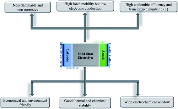
All-solid-state batteries have begun to be commercialized for niche applications as they inch their way into everyday lives. Being devoid of liquids, solid-state batteries can ensure higher levels of safety (nonflammability), possess better electrochemical and thermal stabilities, and are leakproof. The absence of or minimal interactions between the electrolyte and active materials would imply a substantially reduced loss of capacity upon storage/cycling and would render the battery useful at elevated temperatures. Unlike liquid electrolytes, where anion migration causes detrimental polarization effects, charge compensation across the solid-state electrolyte only occurs through the diffusion of active ions.Besides exhibiting high ionic conductivity (of the order of 10−3 S cm−1), a solid electrolyte should ideally possess the following properties for better electrochemical performance in an all-solid-state battery: negligible electronic conductivity, single mobile ion species, high transference number (ratio of electric current due to the mobile ion to the total current), wide electrochemical stability window, chemical and thermal stabilities, compatibility with magnesium metal and high-voltage cathodes, high mechanical strength, and ease of processability in addition to being economical, safe, and environmentally friendly. A schematic enumerating the prerequisites of an ideal electrolyte is shown in Fig. 1. Nevertheless, finding an ideal material to satisfy all the above-mentioned attributes is formidable; the optimization of parameters according to specific needs is more viable.
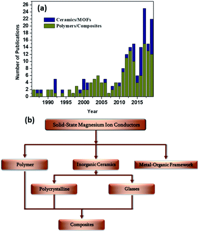
A surge in the number of publications dedicated toward the discovery of novel solid-state magnesium-ion conductors in the last decade (Fig. 2(a)) has indicated that the stage has been set for significantly improved advancements in the field of rechargeable magnesium-based solid-state batteries. In this review, various solid-state material systems that involve Mg2+-ion conduction will be covered, and the properties with respect to their integration with a solid-state battery will be delineated. The materials systems in this review are broadly classified based on polymers and ceramics (Fig. 2(b)). Inorganic polycrystalline ceramics, glasses, and metal–organic frameworks (MOFs) will be covered among the ceramic materials, which will be followed by detailed discussions on the advancements made in the field of solid polymer electrolytes (SPEs) and gel polymer electrolytes (GPEs), as well as ceramic–polymer-based composite electrolytes. In the end, we offer an outlook for further research in the search for an ideal Mg2+-ion-conducting solid-state electrolyte.
2.1. Ceramic-based solid electrolytes
The following sections present discussions on the ionic conductivities associated with various Mg2+-ion solid-state polycrystalline ceramics, which are categorized into inorganic oxides, hydrides, and chalcogenides, as well as MOFs.![[3 with combining macron]](https://www.rsc.org/images/entities/char_0033_0304.gif) c structure, which was the same as that of the NaZr2(PO4)3 (NASICON) crystal structure, although a secondary magnesium-deficient phase of zirconium oxyphosphate (Zr2O(PO4)2) was also present. Later, Kazakos-Kijowski et al.63 developed a sol–gel route to synthesize pure Mg0.5Zr2(PO4)3 and found that the material crystallized in monoclinic P21/n symmetry (similar to that in β-Fe2SO4) as the rhombohedral phase did not account for certain peaks that occurred in the XRD pattern. A schematic of the crystal structure of Mg0.5Zr2(PO4)3, viewed along the b-axis is shown in Fig. 3(a). The crystal structure reveals that ionic diffusion occurs across the channels formed by three PO4 tetrahedra and three ZrO6 octahedra forming a three-dimensional network of tunnels. The size of these channels (4.5–4.7 Å) is such that they are larger than the edges of magnesium tetrahedra (3.3–3.7 Å).64 Recently, a sol–gel-processed pure Mg0.5Zr2(PO4)3 phase was shown to exhibit better ionic conductivity of 7.23 × 10⁻³ S cm−1 at a relatively lower temperature of 725 °C without a considerable change in the activation energy;65 this was likely due to the high density (99% of the theoretical density) of ceramic pellets. However, a composite formed by the distribution of a secondary phase of ZrO(PO4)2 in the parent Mg0.5Zr2(PO4)3 ceramic system led to improved ionic conductivity of 6.92 × 10⁻³ S cm−1 at 800 °C for an optimized composition of Mg1.4Zr4P6O24.4 + 0.4Zr2O(PO4)2.66 This behavior could be attributed to the reduced grain-boundary resistance toward ionic migration due to the presence of a secondary phase. However, the net activation energy of the composite was as high as 1.14 eV, yielding much higher apparent room-temperature ionic conductivity.
c structure, which was the same as that of the NaZr2(PO4)3 (NASICON) crystal structure, although a secondary magnesium-deficient phase of zirconium oxyphosphate (Zr2O(PO4)2) was also present. Later, Kazakos-Kijowski et al.63 developed a sol–gel route to synthesize pure Mg0.5Zr2(PO4)3 and found that the material crystallized in monoclinic P21/n symmetry (similar to that in β-Fe2SO4) as the rhombohedral phase did not account for certain peaks that occurred in the XRD pattern. A schematic of the crystal structure of Mg0.5Zr2(PO4)3, viewed along the b-axis is shown in Fig. 3(a). The crystal structure reveals that ionic diffusion occurs across the channels formed by three PO4 tetrahedra and three ZrO6 octahedra forming a three-dimensional network of tunnels. The size of these channels (4.5–4.7 Å) is such that they are larger than the edges of magnesium tetrahedra (3.3–3.7 Å).64 Recently, a sol–gel-processed pure Mg0.5Zr2(PO4)3 phase was shown to exhibit better ionic conductivity of 7.23 × 10⁻³ S cm−1 at a relatively lower temperature of 725 °C without a considerable change in the activation energy;65 this was likely due to the high density (99% of the theoretical density) of ceramic pellets. However, a composite formed by the distribution of a secondary phase of ZrO(PO4)2 in the parent Mg0.5Zr2(PO4)3 ceramic system led to improved ionic conductivity of 6.92 × 10⁻³ S cm−1 at 800 °C for an optimized composition of Mg1.4Zr4P6O24.4 + 0.4Zr2O(PO4)2.66 This behavior could be attributed to the reduced grain-boundary resistance toward ionic migration due to the presence of a secondary phase. However, the net activation energy of the composite was as high as 1.14 eV, yielding much higher apparent room-temperature ionic conductivity.
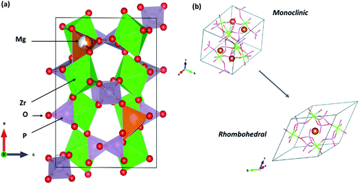 | ||
| Fig. 3 (a) Crystal structure of Mg0.5Zr2(PO4)3 (β-Fe2SO4 structure) viewed along its b-axis (drawn using VESTA) and (b) its rhombohedral crystal structure variant. Reproduced from ref. 70 with permission, copyright 2019, Royal Society of Chemistry. | ||
Whether the structure is monoclinic or rhombohedral largely determines the ionic conductivity of Mg0.5Zr2(PO4)3. In general, materials that are from the NASICON family can crystallize in either the rhombohedral or monoclinic structure, which are associated with the space groups R![[3 with combining macron]](https://www.rsc.org/images/entities/char_0033_0304.gif) c and C2/c, respectively.67,68 The rhombohedral structure consists of two distinct sites arranged in a zigzag manner for the conduction of mobile ions (sites 1 and 2). However, the monoclinic structure possesses an additional third site (site 3) as site 2 is split into two positions in these crystal systems. As a result, the diffusion of mobile species occurs across site 2–1–2 or site 3–1–3. However, the conduction pathway in a monoclinic-structured Mg0.5Zr2(PO4)3 is still unclear as the crystal structure varies from that of Na-based NASICON. In addition, NASICON monoclinic structures may exhibit a phase transition at higher temperatures to a rhombohedral structure that can yield more facile mobility of ions due to the concomitant enlargement in the size of the bottleneck (also known as order–disorder transition). In the case of Mg0.5Zr2(PO4)3, such a transition is yet to be conclusively proven as the phase transition occurring at 670–680 °C has only been mentioned based on thermal studies without any high-temperature structural data to corroborate the claim.69 A recent theoretical analysis based on the first-principles molecular dynamics (FPMD) studies comparing the ionic diffusions in monoclinic and rhombohedral crystal structures of Mg0.5Zr2(PO4)3 conveys an intriguing aspect.70 The centrosymmetric rhombohedral structural variant of Mg0.5Zr2(PO4)3 is shown in Fig. 3(b). From the FPMD calculations, it is evident that ionic diffusion was more feasible in a rhombohedral structure as compared to that in the β-Fe2SO4 structure, and it exhibited lower activation energy of 0.63 eV. Further, the computational studies confirmed that three-dimensional conduction occurred in the rhombohedral structure, similar to that in the monoclinic structure. Such characteristics are identical to the ionic transport observed in sodium-based NASICON compounds, where stabilizing the rhombohedral structure enhances the net ionic conduction of the material.71 Unfortunately, there has been no experimental evidence, so far, on the synthesis of pure Mg0.5Zr2(PO4)3 with a rhombohedral crystal structure. Nevertheless, the authors do suggest that the rhombohedral structure may be stabilized in Mg0.5Zr2(PO4)3 by thin-film synthesis or doping since the energy difference in the phase stabilities of both the structures was found to be only around 14 meV per atom.70 Indeed, in another experimental study, by partially introducing Hf4+ ions in the Mg2+ site in the above composition, the monoclinic structure transformed into a rhombohedral structure (associated with the space group R
c and C2/c, respectively.67,68 The rhombohedral structure consists of two distinct sites arranged in a zigzag manner for the conduction of mobile ions (sites 1 and 2). However, the monoclinic structure possesses an additional third site (site 3) as site 2 is split into two positions in these crystal systems. As a result, the diffusion of mobile species occurs across site 2–1–2 or site 3–1–3. However, the conduction pathway in a monoclinic-structured Mg0.5Zr2(PO4)3 is still unclear as the crystal structure varies from that of Na-based NASICON. In addition, NASICON monoclinic structures may exhibit a phase transition at higher temperatures to a rhombohedral structure that can yield more facile mobility of ions due to the concomitant enlargement in the size of the bottleneck (also known as order–disorder transition). In the case of Mg0.5Zr2(PO4)3, such a transition is yet to be conclusively proven as the phase transition occurring at 670–680 °C has only been mentioned based on thermal studies without any high-temperature structural data to corroborate the claim.69 A recent theoretical analysis based on the first-principles molecular dynamics (FPMD) studies comparing the ionic diffusions in monoclinic and rhombohedral crystal structures of Mg0.5Zr2(PO4)3 conveys an intriguing aspect.70 The centrosymmetric rhombohedral structural variant of Mg0.5Zr2(PO4)3 is shown in Fig. 3(b). From the FPMD calculations, it is evident that ionic diffusion was more feasible in a rhombohedral structure as compared to that in the β-Fe2SO4 structure, and it exhibited lower activation energy of 0.63 eV. Further, the computational studies confirmed that three-dimensional conduction occurred in the rhombohedral structure, similar to that in the monoclinic structure. Such characteristics are identical to the ionic transport observed in sodium-based NASICON compounds, where stabilizing the rhombohedral structure enhances the net ionic conduction of the material.71 Unfortunately, there has been no experimental evidence, so far, on the synthesis of pure Mg0.5Zr2(PO4)3 with a rhombohedral crystal structure. Nevertheless, the authors do suggest that the rhombohedral structure may be stabilized in Mg0.5Zr2(PO4)3 by thin-film synthesis or doping since the energy difference in the phase stabilities of both the structures was found to be only around 14 meV per atom.70 Indeed, in another experimental study, by partially introducing Hf4+ ions in the Mg2+ site in the above composition, the monoclinic structure transformed into a rhombohedral structure (associated with the space group R![[3 with combining macron]](https://www.rsc.org/images/entities/char_0033_0304.gif) c, close to the NASICON structure), leading to ionic conductivity of 2.1 × 10⁻⁶ S cm−1 at 300 °C and activation energy of 0.66 eV for the optimized composition of (Mg0.1Hf0.9)4/3.8Nb(PO4)3.72 This could further vouch for the significance of a rhombohedral structure, as seen earlier, toward the improved diffusion of magnesium ions in such structures.
c, close to the NASICON structure), leading to ionic conductivity of 2.1 × 10⁻⁶ S cm−1 at 300 °C and activation energy of 0.66 eV for the optimized composition of (Mg0.1Hf0.9)4/3.8Nb(PO4)3.72 This could further vouch for the significance of a rhombohedral structure, as seen earlier, toward the improved diffusion of magnesium ions in such structures.
Mg0.5Zr2(PO4)3—the base structure—presents opportunities for substituting aliovalent ions at the Zr- and P-sites to accommodate more magnesium ions in the structure. Several dopants such as Zn2+, Al3+, Fe3+, Si4+, Ce4+, and Nb4+ have been studied, yielding different results.72–84 The complete replacement of Zr4+ by Si4+, with the Mg0.5Si2(PO4)3 composition, led to the same monoclinic structure as that in Mg0.5Zr2(PO4)3, but with much higher ionic conductivity of 1.06 × 10⁻⁶ S cm−1 (ref. 75) at room temperature (vs. 5 × 10⁻¹³ S cm−1 at room temperature for Mg0.5Zr2(PO4)3 determined by extrapolating from the Arrhenius plot). With the material crystallizing in the same monoclinic structure, the reduction of the unit cell volume could be the reason for the increase in ionic conductivity, which provided an appropriate bottleneck size for more feasible Mg2+-ion propagation. In addition, Mg0.5Si2(PO4)3 exhibited a wide electrochemical window of up to 3.2 V, which is the highest value reported so far for an inorganic-oxide-based system, although details regarding the cell assembly are missing. The temperature-dependent conductivity behavior has not been investigated for this system yet; hence, its activation energy is not known. Halim et al.76 further improved the room-temperature ionic conductivity by doping Mg0.5Si2(PO4)3 with Al3+ ions to create more interstitial sites in the lattice, yielding a higher charge carrier concentration in the system. The resultant composition of Mg0.625Si1.75Al0.25(PO4)3 exhibited bulk ionic conductivity of 2.78 × 10⁻⁵ S cm−1 at room temperature, which is more than 10 times the parent composition. However, Al doping also resulted in a reduction in the electrochemical stability window to 2.5 V.
Moving away from mainstream NASICON-based magnesium-ion conductors, a sol–gel-synthesized composite structure based on the β-MgSO4:Mg(NO3)2–0.4MgO composition also exhibited relatively good ionic conductivity in the region of 2 × 10⁻⁶ S cm−1 at room temperature.85 This high conductivity seems to have been facilitated by the presence of β-MgSO4 in the amorphous form across the MgO particles. With a crystal structure based on trivalent-ion-conducting Sc2(WO4)3, Mg2+-ion conduction in magnesium hafnium tungstate (Mg(Hf(WO4)3)) was found to be around 2.5 × 10⁻⁴ S cm−1 at 600 °C associated with activation energy of 0.84 eV.86 The ionic transport in these materials was facilitated by the alternating arrangement of Hf4+ and Mg2+ ions along the (010) direction (as shown in Fig. 4(a)), which may lead to inhomogeneity in the bond strengths in the Hf–O and Mg–O bonds. This inhomogeneity may cause a weakening in the Mg–O bonds. The alternating arrangement was further corroborated by HAADF-STEM imaging, as shown in Fig. 4(b), with each light and dark vertical line reflecting the alternating arrangement of Mg4+ and Hf4+ ions between the W interlayers.
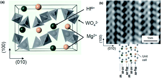 | ||
| Fig. 4 (a) Structural arrangement of Mg2+ and Hf4+ between the two layers of WO4 tetrahedra in an orthorhombic crystal structure viewed along the c-axis and (b) high-resolution HAADF-STEM image showing the alternating Mg2+ and Hf4+ ionic arrangement. Reproduced from ref. 86 with permission, copyright 2011, Wiley. | ||
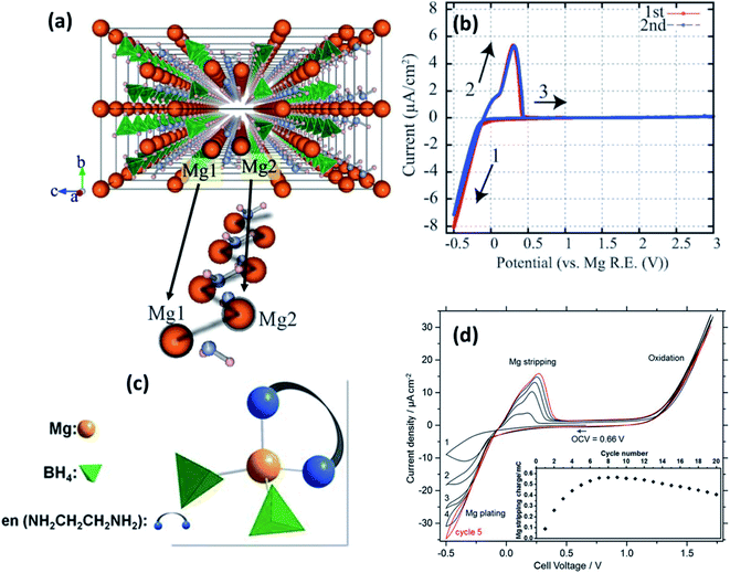 | ||
| Fig. 5 (a) Crystal structure of Mg(BH4)(NH2) viewed along the a-axis and an enlarged image of the Mg-ion zigzag arrangement; cyclic voltammograms of (b) Pt/Mg(BH4)(NH2)/Mg (reproduced from ref. 89 with permission, copyright 2013, Royal Society of Chemistry) and (d) Pt/Mg(en)1(BH4)2/Mg cell at 60 °C; (c) tetrahedral arrangement of coordinating ions in Mg(en)1(BH4)2. Reproduced from ref. 96 with permission, copyright 2017, Nature. | ||
By fine-tuning the synthesis conditions of Mg(BH4)(NH2) (by optimizing the duration of ball milling and annealing), Le Ruyet et al.91 was successful in enhancing the bulk ionic conductivity by three orders of magnitude as compared to the value reported Higashi et al.89 A sample prepared by ball milling at 400 rpm followed by annealing at 120 °C for 72 h under 10 bar of hydrogen yielded ionic conductivity of 3 × 10⁻⁶ S cm−1 at 100 °C. Such a drastic increase in the ionic conductivity could be ascribed to the presence of a fraction of the phase in the amorphous state, which was detected by 11B MAS-NMR analyses. This results in a glass–ceramic-like composite structure as the resultant product. Similar characteristics have been observed in other Li-ion glass–ceramic systems, such as LiAlO2, Li2O2, and LiTaO3, where the glass phase acts as a facile conduit for the conduction of ions.92–95 The formation of such an amorphous phase may have been facilitated by the high-speed ball-milling process.92–94
Intriguingly, however, the ionic conduction in borohydrides was found to be further improved by the integration of a neutral bidentate ethylenediamine ligand (NH2CH2CH2NH2, “en”) synthesized by the mechanical milling of Mg(BH4)2 and Mg(en)(BH)2 at stoichiometric ratios in an inert atmosphere.96 This ligand inclusion resulted in ionic conductivity in the range of 5 × 10⁻⁸ S cm−1 at room temperature and increased to 6 × 10⁻⁵ S cm−1 at 70 °C, which is a substantial improvement over those obtained from other hydrides and even several oxides. The crystal structure of this compound is unavailable at the time of writing, although by a combination of Raman and IR spectroscopies, Mg2+ ions were found to be coordinated by two BH4 units and a bidentate unit in the cis-configuration (Fig. 5(c)). Such coordination is understood to have induced asymmetry in the charge distribution of Mg2+ cations, which played a role in the enhancement of ionic conductivity. However, the activation energy for ionic conduction in this compound was found to be extremely high, approximately 1.6 eV. Fig. 5(d) shows the stripping/deposition curves of Mg2+ ions in Pt/Mg(en)(BH)2/Mg cell recorded at 60 °C at a scan rate of 10 mV s−1. The onset of magnesium plating on platinum electrodes was observed at −0.2 V vs. Mg2+/Mg; above 1.2 V, the irreversible oxidation of the electrolyte seems to have occurred. Further, there is an improvement in the stripping/plating current density during the initial seven cycles, as shown in the inset of Fig. 5(d); thereafter, the current saturates. This behavior could be attributed to the intermediate phase, which can evidently conduct Mg2+ ions formed during stripping/plating due to irreversible oxidation beyond 1.2 V. It is speculated that this intermediate phase improved the interfacial connectivity between the electrolyte and electrodes. However, further investigations are needed to prove the nature of this intermediate phase.
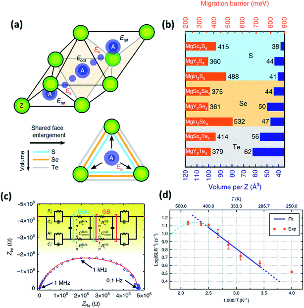 | ||
| Fig. 6 (a) Migration path of Mg2+ ions in a MgX2Z4 spinel structure, where two stable tetrahedral equivalent sites are connected by a high-energy octahedral interstitial site; (b) migration barrier calculated for different magnesium spinels using first-principles calculations; (c) Nyquist plot of the Ta/MgSc2Se4/Ta cell, where the red curve signifies the equivalent circuit fitting done using Jamnik–Maier elements; and (d) spin-lattice relaxation data of 25Mg recorded as a function of temperature; the blue line indicates the Arrhenius fit. Reproduced from ref. 97 with permission, copyright 2017, Nature. | ||
In normal spinel structures, the tetrahedral sites are interconnected by triangular anion cages shared across an adjacent octahedral site, and these three-coordinated anions form the ionic transport channels that influence the net activation energy of the crystal system. Therefore, it is necessary that these channels are sufficiently wide for facile ionic migration. Consequently, the size of the anion plays an important role in reducing the migration barrier. In addition to widening the ion diffusion channels, a larger anion also increases the electric polarizability of the system, which, in turn, increases the ionic conductivity of the crystal system. This variation in the migration barrier as a function of anion size can be observed, as shown in Fig. 6(b). The effect of metal cation (In, Sc, or Y) seems to be less significant and may facilitate a reduction in the energy difference between the octahedral and tetrahedral sites.
It remains imperative that spinels do not undergo any antisite disorder or transform into inverse spinel structures, where Mg2+ ions occupy the octahedral sites and are connected across a vacant tetrahedral site.97 Under these circumstances, the transport of ions occurs in the oct–tet–oct topology. Recent theoretical studies (based on nudged elastic band calculations) on inverse-spinel-prone MgIn2S4 systems have shown that the migration barriers across the oct–tet–oct topology are much higher as compared to those across the tet–oct–tet configuration so much so that the migration channels can be considered to be always closed.99
The migration barriers of Mg-based chalcogenides were determined by nudged elastic band simulation in combination with DFT, as shown in Fig. 6(b). Among these material systems, MgY2S4, MgY2Se4, and MgSc2Se4 exhibited the least migration barriers of 360, 361, and 375 meV, respectively. However, only MgSc2Se4 has been successfully synthesized and characterized so far. 25Mg nuclear magnetic resonance measurements on this compound confirmed ionic diffusion in this material from motional narrowing of the resonance peaks as a function of temperature along with the diamagnetic nature of the material. The spin–lattice relaxation was found to be very short (at 0.07–0.3 s within the temperature range, as shown in Fig. 6(d)), and the self-diffusion coefficient and activation energies were determined to be 4.53 × 10⁻⁸ cm−2 s−1 at 450 K and 0.37 eV (close to the theoretically predicted values), respectively. The high ionic conductivity of MgSc2Se4 (10−4 S cm−1 at 298 K) was determined by means of impedance spectroscopy (Fig. 6(c)) and the activation energy was estimated to be as low as 0.2 eV. Although the ionic conductivity was at a record high, this was also accompanied by high electronic conductivity (∼4 × 10⁻⁸ S cm−1), as calculated from the Jamnik–Maier model of equivalent-circuit-based fitting of the Nyquist plot. This high electronic conduction may have originated from the point defects in the material that were formed as a result of Sc3+ ions occupying the Mg2+ sites, as well as the possible existence of electronically conducting secondary phases.97,100
Wang et al.101 employed two routes to suppress the electronic conductivity in MgSc2Se4: introducing excess Se in the material and aliovalent doping of Sc3+ with Ti4+ and Ce4+. The former approach seemed to be counterproductive as the addition of excess Se systematically increased the electronic conductivity from 2.1 × 10⁻⁸ S cm−1 at 5 wt% to 1.1 × 10⁻⁵ S cm−1 at 10 wt% Se. This is not surprising considering the fact that the electronic conductivity of Se is high. Therefore, any residual Se after the firing process would substantially contribute toward the increased electronic conductivity. The latter approach that involved aliovalent doping with Ti4+ and Ce4+ also yielded similar results, except for the MgSc1.9Ti0.075Se4 composition that yielded reduced electronic conductivity of 2.7 × 10⁻⁹ S cm−1. However, the authors proposed to employ selenides as the cathode material due to the combination of high ionic and electronic conductivities. The selenide cathode afforded first- and tenth-cycle capacities of only 40 and 75 mA h g−1, respectively. At any rate, exploiting this material as a cathode is limited by its high material cost and tedious processing conditions.
2.2. MOFs
MOFs feature three-dimensional permanently porous structures built around metal ions and connected through organic ligands.102 Unlike purely inorganic solid electrolytes,103 they are amenable to manipulation, presenting opportunities to alter their composition, pore dimensions, and internal surfaces.104 Apart from the fact that their unique architectures permit the selective diffusion of guest species through them,105 they can also exhibit ionic diffusivities similar to those in molten media because of the confinement effects in their small pores.106 Moreover, unlike that in polymer electrolytes, where ionic conductivity depends on the polymer chain mobility, the conduction in MOFs occurs via a through-the-pore diffusion process, which implies that their conductivity and mechanical properties are not inversely proportional. MOFs are, therefore, of considerable interest for use as robust, crystalline electrolytes in the battery community.107–109Aubrey et al.110 reasoned that MOFs with larger concentrations of open metal sites and capable of coordinating nucleophilic anions could provide the necessary driving force for ions introduced in their pores. These pores are sufficiently large to accommodate higher concentrations of electrolytes as compared to that achievable in the bulk form. In addition, the open metal sites also inhibit the migration of anions and hence increase the transference number of the electrolyte. For MOF-based solid electrolytes, two similar frameworks with a tunable pore diameter have been considered: Mg2(dobdc), 1, (dobdc4− = 2,5-dioxidobenzene-1,4-dicarboxylate) and its expanded analog, namely, Mg2(dobpdc), 2, (dobpdc4− = 4,40-dioxidobiphenyl-3,30-dicarboxylate), as shown in Fig. 7(a) and (b), respectively. One of their electrolytes, an MOF structure of Mg2(dobpdc) soaked in magnesium phenolates and magnesium triflates, exhibited conductivity values as high as 0.25 mS cm−1. However, the only other reported Mg-ion-conducting system was based on a mesoporous anionic Cu-azolate ((CH3)2NH2)[Cu2Cl3BTDD]·(DMF)4(H2O)4.5 MOF that could support the diffusion of different cationic species.111 Unfortunately, the Mg2+-ion conduction in these frameworks was found to be around 8.8 × 10⁻⁷ S cm−1 at room temperature with the associated activation energy of 0.37 eV. This conductivity was considerably improved (up to 0.13 mS cm−1) at room temperature when Miner et al. synthesized a solid electrolyte based on MgBr2 salt in the Cu-azolate framework of Cu4(ttpm)2·0.6CuCl2, where Cu4(ttpm)2 (H4ttpm = tetrakis(4-tetrazolylphenyl)methane) provided multiple anion binding sites.112
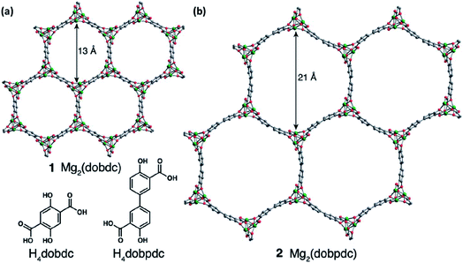 | ||
| Fig. 7 Porous MOF structures of (a) Mg2(dobdc), 1, (dobdc4− = 2,5-dioxidobenzene-1,4-dicarboxylate) and (b) Mg2(dobpdc), 2, (dobpdc4− = 4,40-dioxidobiphenyl-3,30-dicarboxylate). Reproduced from ref. 110 with permission, copyright 2014, Royal Society of Chemistry. | ||
In addition, it is imperative to estimate the Mg-ion transference number for MOF-based systems since there is a probability of protonic conduction occurring in the material due to the presence of water molecules (similar to that in Cu-azolate MOFs) or other organic functional groups.113,114 This possibility of cationic conduction other than magnesium should be eliminated in order to determine the true value of ionic conductivities in MOFs. Information regarding the electrochemical stability window is yet to be obtained in these materials. Nevertheless, MOFs have opened a new window for research considering that not only their architecture and ligand type but also other features such as particle morphology, framework topology, and solvent polarity can influence the electrolyte properties. MOF-based electrolytes have been touted to be emerging alternatives to polymer-/ceramic-based electrolytes. Wu and Lou,115 however, warned that the chemical/electrochemical stabilities, mechanical strength, and processability should be assessed before MOFs can be considered for commercial exploitation for use in devices. Among the variants of MOFs, Prussian blue (PB) analogs could also be explored for their use as electrolytes owing to their ability to modulate the channels to become sufficiently large for the migration of highly polarizing divalent and trivalent ions.116 However, these materials have been predominantly researched for their use as high-voltage intercalation cathodes and are yet to step into the fold of solid electrolytes. However, if PB-based MOFs can withstand the electrochemical window of magnesium-based batteries, they can prove to be a good candidate worthy of investigation.
2.3. Glasses
The field of glasses and glass-based ceramics has come a long way since Warburg discovered ionic conduction in glasses more than a century ago. Today, glasses are one of the frontrunners in the race for fabricating an ideal electrolyte for use in all-solid-state batteries.117–119 The ionic transport in an amorphous or disordered system is fairly different than that in its crystalline counterparts. The periodic energy landscape in a crystalline system is replaced with uneven potential wells (an approximate representation is shown in Fig. 8(a) and (b)).120 Hence, there is a distribution of barriers for the ions to hop from one site to another, and the barrier heights are influenced by the interaction of the mobile species with the surrounding environment.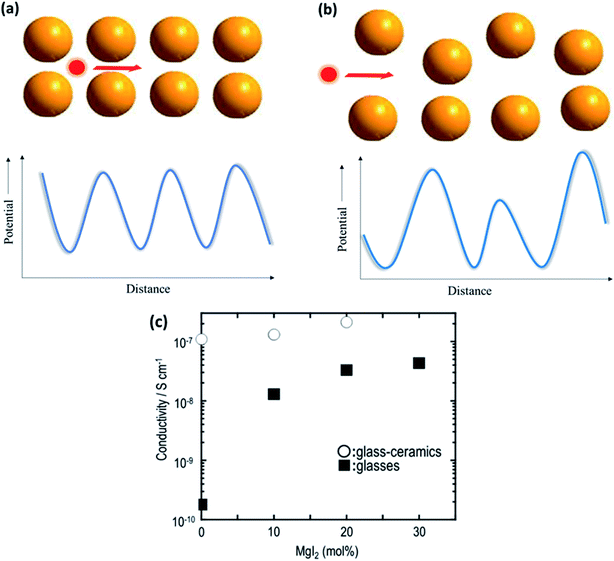 | ||
| Fig. 8 Potential energy landscape for (a) crystalline and (b) amorphous materials for the transport of ions; (c) plot of ionic conductivity as a function of MgI2 concentration in 60MgS–40P2S5 parent glass. Reproduced from ref. 123 with permission, copyright 2014, Elsevier. | ||
Glasses are better than crystalline materials as candidates for use as electrolytes in all-solid-state batteries because of the following advantages: absence of grain boundaries and porosity, isotropic properties, good thermal stability, negligible electronic contribution to conductivity, dimensional flexibility, and compositional tunability. Although there are several superionic conducting-glass-based materials that can conduct Li+, Na+, and Ag+ ions, the field of Mg2+-ion-conducting glasses is in its infancy.121,122 In a recent study on the Mg-based analogs of Li2S–P2S5 glasses, Yamanaka et al.123 discussed the ionic conductivity of MgS–P2S5–MgI2 glasses synthesized by a mechanochemical technique. The parent composition of 60MgS–40P2S5 exhibited ionic conductivity in the region of ∼10−10 S cm−1 at 200 °C, which was drastically improved by 2 orders of magnitude (4.3 × 10⁻⁸ S cm−1 at 200 °C) by the addition of MgI to the glass network. This was understood based on the expansion of the glass network by the inclusion of a larger anion in the form of iodine, resulting in larger channels for ionic transport. Interestingly, the heat treatment of these glasses led to the precipitation of nanocrystalline Mg2P2S6, which further increased the bulk ionic conductivity to 2.1 × 10⁻⁷ S cm−1 at 200 °C. The variation in the ionic conductivity as a function of the amount of MgI in glass is shown in Fig. 8(c). However, more work is needed to formulate better Mg2+-ion-conducting glass. Therefore, the major impetus is toward the development of better conducting-glass-based magnesium-ion-based solid electrolytes. There is some hope from magnesium phosphorus oxynitride thin films, which are similar to their lithium counterpart, LiPON, which has ionic conductivity of 1.3 × 10⁻⁶ S cm−1 at 210 °C associated with the activation energy of 1.3 eV.124
2.4. Polymer-based solid electrolytes
Because of their mechanical flexibility, low weight, and ease of processing, polymers can add a different dimension to the research on solid-state electrolytes. Polymer electrolytes are primarily categorized into solid, gel, and composite polymer electrolytes. Solid polymer electrolytes (SPEs) comprise a mobile-ion-containing salt dissolved in the polymer that forms a complex with the crosslinked chains. However, SPEs afford low ionic conductivities as the conductivity in such systems is limited by the polymer chain segmental motion. In contrast, gel polymer electrolytes (GPEs) are ionic salts dissolved in plasticizers/solvents that form a gel within a polymer matrix. This results in an increase in ionic conductivity, although the mechanical strength can be reduced. GPEs have been extensively investigated for lithium battery applications.125,126 The third category comprises composites formed by the inclusion of ceramic fillers in a polymer matrix, which will be discussed in the subsequent section.Similar to liquid electrolytes, the ionic conductivity of polymer electrolytes depends on the ability of the salts to dissociate in the polymer electrolytes. A well-dissociated ionic complex can enable the free propagation of mobile Mg2+ ions across the polymer. Ionic conduction in polymeric systems occurs as a consequence of segmental motion of the polymer chains.127 Amorphous regions of the polymer chains create space for ions to migrate across the polymer by continuous hopping from one chain to another that is coordinated by polar groups present in the polymer. The crystalline regions, on the other hand, block the propagation of ions due to the restricted motion of polymer chains. Therefore, GPEs exhibit higher ionic conductivity than SPEs, as the crystallization of the polymer network is suppressed in the gel, which increases the ionic conductivity. The salt concentration is another defining factor that improves the net ionic conductivity. A higher content of ionic salt results in reduced ionic dissociation and adversely affects polymer chain motion, leading to reduced ionic conductivity. Hence, it is important to optimize the salt concentration in the polymer electrolyte for achieving higher ionic conductivity. However, Jeong et al. suggested that the Mg2+-ion-conduction mechanism, which is decoupled from the segmental motion of polymer chains, is facilitated by the presence of large ionic aggregates (size: 500 nm) in the SPE system.128
SPE formation depends on the solvation energy and difference between the lattice energies of the ionic salt and polymer. Minimal lattice energies of the constituents are preferred for better stability of the SPE. Polymer electrolytes employ a combination of salts with polymer matrices such as polyethylene oxide (PEO), polyethylene glycol (PEG), polyvinylidene difluoride (PVDF), polymethyl methacrylate (PMMA), and polyacrylonitrile (PAN). Examples of typical salts are magnesium perchlorate (Mg(ClO4)2), magnesium trifluoromethyl sulfonyl imide (Mg[(CF3SO2)2N]2), magnesium triflate (Mg(CF3SO3)2), and magnesium chloride (MgCl2).129–145 Thin films of polymer electrolytes can be fabricated via two common techniques: solution-cast method and hot-press technique. The former technique requires the dissolution of a polymer and an ionic salt (with or without a plasticizer) in a common solvent, which are subsequently dried in a vacuum. In the second technique, a dry homogeneous mixture of a polymer, salt, and/or filler ceramic material is heated to a temperature close to the melting point of the polymer and pressed between metal plates/twin rollers to yield thin films (in the range of micrometers).
The variation in the ionic conductivity as a function of temperature for various GPEs is shown in Fig. 9. In several polymer electrolyte systems, the Arrhenius plot of conductivity as a function of temperature assumes a convex shape rather than a single line. This is due to the temperature-dependent relaxation processes that occur owing to the polymer chain motion. One of the earliest papers on polymer electrolytes appeared in 1986 in which the room-temperature ionic conductivities of 10−6 and 10−10 S cm−1, respectively, were reported for perchlorates and thiocyanates complexed with PEO.142 This was soon followed by a blend of MgCl2 in PEO, which yielded low ionic conductivity of around 10−9 S cm−1 and a negligible transference number (∼0.005).141 However, these salts are incompatible with magnesium-metal electrodes, rendering their use as a solid electrolyte futile.
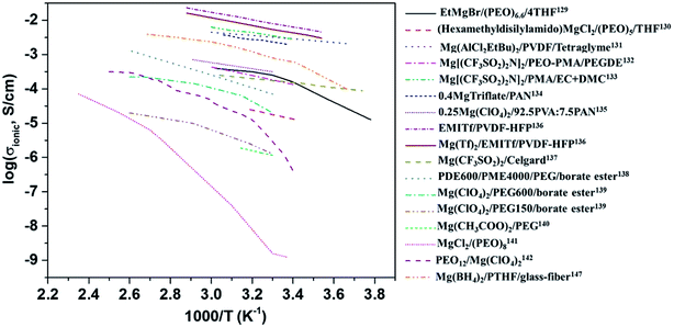 | ||
| Fig. 9 Plot of variations in the ionic conductivities as a function of temperature for various polymer electrolytes. | ||
Liebenow129,143 fabricated the first polymer electrolyte using a magnesium-metal-compatible Grignard reagent (ethyl magnesium bromide, EtMgBr) dissolved in PEO plasticized with small amounts of diethyl ether or tetrahydrofuran. The highest ionic conductivity exhibited by these polymer electrolytes was up to 10−4 S cm−1 at 40 °C.143 The stability of the salt with respect to magnesium metal is also crucial. Chusid et al.131 chose to immobilize electrolyte solutions of magnesium organo-haloaluminates, such as Mg(AlCl2EtBu)2, in tetrahydrofuran and tetraglyme in the polymer matrices of PEO and PVDF. The plasticizers used in these systems helped soften the polymers. The authors successfully demonstrated the reversible deposition/stripping of magnesium on Au electrodes from both PEO- and PVDF-based polymer systems. The highest ionic conductivity (3.7 mS cm−1 at 25 °C) and the widest electrochemical window (2.5 V) were exhibited by the Mg(AlCl2EtBu)2/tetraglyme/PVDF system; its cyclic voltammetric curve is shown in Fig. 10(a). It is reassuring that the electrolyte is not only compatible with magnesium metal but also supports the reversible intercalation of magnesium in Chevrel-phase Mo6S8 with room-temperature capacity of 80 mA h g−1 (theoretical capacity: 122 mA h g−1). Understandably, the capacity is dependent on temperature. It is noteworthy that capacity close to the theoretical value could be realized at 60 °C (Fig. 10(b)). The cyclability of an Mg-alloy/Mg(AlCl2EtBu)2-tetraglyme-PVDF-electrolyte/MgxMo6S8 system between 0.9 and 1.2 V is shown in Fig. 10(b).
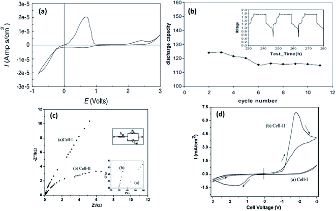 | ||
| Fig. 10 Cyclic voltammetric curve recorded for Au/PVDF-Mg(AlEtBuCl2)2-tetraglyme/Mg; (b) plot of discharge capacity vs. cycle number recorded at 80 °C for a battery with Mo6S8 cathode, PVDF-Mg(AlEtBuCl2)2-tetraglyme solid electrolyte, and AZ-31 Mg alloy anode (inset shows the voltage–time curve for the same battery). Reproduced from ref. 131 with permission, copyright 2003, Elsevier; (c) Nyquist plots and (d) cyclic voltammograms of cell 1 (SS|EMITf-PVDF-HFP|SS) and cell 2 (Mg|EMITf-PVDF-HFP|Mg) recorded at room temperature. Reproduced from ref. 136 with permission, copyright 2009, Wiley; inset in (c) shows the enlarged high-frequency region of the Nyquist plot. | ||
Yoshimoto et al.133 showed that ionic conductivity as high as 2.8 × 10⁻³ S cm−1 at room temperature could be achieved with Mg[(CF3SO2)2N]2 dissolved in a PEO-PMMA polymer matrix plasticized with ethylene carbonate and dimethyl carbonate. As mentioned earlier, the dissociation of ions defines the ionic conductivity in a gel-based polymer system; hence, the popular inclusion of borate ester was performed by Saito et al.,139 who reported not only enhanced net ionic conductivity but also improved Mg2+-ion transference number (>0.50). The borate ester group closely holds together the anions in the polymeric system, facilitating the increased propagation of Mg2+ ions, as reflected in the increased ionic conductivity and higher transference number. The highest ionic conductivity of 4.8 × 10⁻³ S cm−1 at room temperature, comparable to that of liquid electrolytes, was achieved with a blend of 1-ethyl-3-methylimidazolium trifluoromethanesulfonate (EMITf) and magnesium triflate in poly(vinylidene fluoride-co-hexafluoropropylene) (PVDF-HFP), with a relatively low transference number of 0.26.136 The electrochemical window of the GPE was determined to be 3.5 V. By using two symmetric electrode set-ups—one with stainless steel (cell 1) and the other with magnesium metal (cell 2), the ionic conductivity of the electrolyte was determined from the low-frequency tail and semicircular arc in the impedance plots (Fig. 10(c)) from cells 1 and 2, respectively. Further, the impedance plots reveal the internal resistance (see inset in Fig. 10(c)). For cell 2, the internal resistance was around 6 kΩ cm2 as compared to that of 80 kΩ cm2 for cell 1. Cyclic voltammograms show that this GPE supports the stripping/deposition of magnesium (Fig. 10(d)). Such high internal resistances, sometimes called interfacial resistance, could result in the fast decay of specific capacity of a solid-state battery. This has been the characteristic of several other magnesium-based polymer electrolytes and is relatively higher than the values reported for lithium-metal/polymer cells. The internal resistance in polymer-based solid electrolyte cells has been understood to be caused by surface films by the accumulation or decomposition of charges across the cathode–electrolyte interface, and the resistance is induced by charge transfer.146 Internal resistance may also be influenced by improper contact between the electrolyte and electrodes. For better cyclability in a battery, it is imperative that the internal resistance is kept to a minimum. The interfacial resistance arising between the electrolytes and electrodes can lead to poor cycling efficiency even in polymer electrolytes with superior ionic conductivities and wider electrochemical windows.167,170
In 2019, Du et al.147 demonstrated a GPE formed by the in situ crosslinking of [Mg(BH4)2] and hydroxyl-terminated polytetrahydrofuran (PTHF) in a glass-fiber-membrane support structure. In this composition, the high basicity of Mg(BH4)2 was circumvented by the reaction of BH4− and hydroxyl-terminated PTHF. A schematic of the synthesis of PTHF-borohydride-based GPE is shown in Fig. 11(a). To obtain low overpotential and enhanced electrochemical performance, MgCl2 was employed as the intermediary that forms a chloride complex with borohydride without altering the magnesium coordination and without affecting the BH4− anion. Owing to the reduced mechanical strength of GPE after the crosslinking process, the material was infiltrated into a glass fiber membrane, which, in turn, provides strength and good flexibility. With the optimum composition of the GPE–glass fiber system, the maximum ionic conductivity of 4.76 × 10⁻⁶ S cm−1 could be obtained at room temperature. In addition, this material exhibited a high transference number of 0.73 at room temperature. An excellent electrochemical performance was noted with this GPE when it was used with Mo6S8 cathode and magnesium-metal anode: a gradual decrease in overpotential with cycling (Fig. 11(b)–(d)); 0.1C capacity of 80.6 mA h g−1 and 1C capacity of 66.9 mA h g−1 (theoretical capacity: 128.8 mA h g−1); and near-perfect coulombic efficiency of 74 mA h g−1 over 250 cycles associated with 0.5C capacity (Fig. 11(e)). As shown in Fig. 11(h)–(k), a battery constructed using this GPE could power an LED in the 1.8–2.2 V range. Moreover, this battery could still operate even after splitting it into two halves, which implies the absence of electrolyte leakage under such damage.
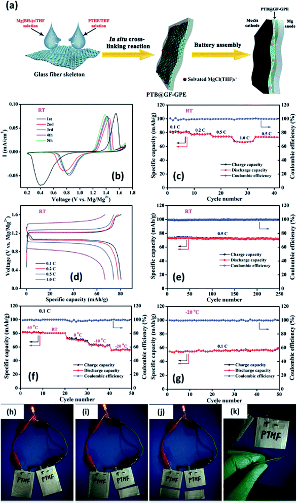 | ||
| Fig. 11 (a) Schematic of the synthesis of a GPE of borohydride–polytetrahydrofuran impregnated in a glass fiber. Electrochemical characterization of a Mo6S8//GPE//Mg cell at room temperature (b–e) and between 60 and −20 °C (f–g). Lighting an LED using a soft-package Mo6S8//GPE//Mg battery (h–k). Reproduced from ref. 147 with permission, copyright 2019, Wiley. | ||
Recent studies148,149 involving the fabrication of single-ion-conducting GPEs (transference number close to unity) have yielded block copolymers produced from the copolymerization of polyethylene glycol dimethacrylate (PEGDMA) and potassium 4-styrenesulfonyl(trifluoromethylsulfonyl)imide (KSTFSI) monomer. The resultant copolymer was subsequently swelled in an appropriate solvent (dimethyl sulfoxide (DMSO)), which is compatible with magnesium metal. The copolymer exhibited ionic conductivity as high as 0.1 mS cm−1 at room temperature, but the hindrance in magnesium deposition from the solvated cation remains a problem owing to the large charge transfer resistance.
2.5. Composites
As the mechanical stability of GPEs is still under investigation, attempts have been made to impart structural stability to GPEs by dispersing ceramic filler particles into the polymer matrix. This provides an apt platform for ceramic–polymer-based composite electrolytes to outperform both pure polymer and ceramic electrolytes. The composite approach can combine the advantages of the polymer phase as the matrix and the ceramic particles as the filler, which can yield a solid electrolyte with tunable physical properties. Ideally, a ceramic–polymer-based composite can help achieve better interfacial stability and increased transference number in addition to improving the bulk ionic conductivity of the material.150,151 Based on the type of contribution of the filler to the net ionic conduction in the electrolyte, a ceramic–polymer-based composite can be categorized according to its filler material as passive (or inert) or active.With regard to passive fillers, ceramic particles can enhance the net ionic conduction in a composite without directly conducting any mobile ions. The ionic conduction in such composites undergoes two different phases, which is a function of the composition of the filler material.152,153 The initial addition of filler particles results in a gradual increase in the ionic conductivity until it reaches the maxima. This increase is aided by the space-charge polarization induced by the filler–polymer interface. Space charge refers to an accumulation/depletion of local, uncompensated charges in solids. It could be due to the absorption of charged species on a dielectric surface, thermal ionization, or migration (sometimes field-assisted) of point defects. Interfaces, such as grain boundaries, provide active sites for the creation and retention of space charges. Space charge can be transient or permanent, temperature-dependent, or field-sensitive depending on the nature of the interface. The interface–space charge relationship is so complex that it is often difficult to quantify its effect on the bulk electrical properties. Space charge can exert a significant influence on the ionic and electronic conductivities of nanocomposites. For example, high space-charge polarization can facilitate charge separation (e.g., Mg2+ and ClO4−) in a polymer network, enhancing the ionic conductivity. Moreover, the inclusion of filler particles suppresses the crystallization of polymers, allowing large amorphous regions to provide more chains that facilitate ion transport across the electrolyte by segmental motion. However, beyond the maxima, any further addition of filler particles can lead to decreased ionic conductivity as a result of the blocking effect, i.e., ionic diffusion is obstructed by the large particles residing in the matrix.
In the literature, a few reports have discussed solid-state electrolytes with the inclusion of passive fillers, such as TiO2, B2O3, and SiO2, in polymer matrices.154–157 Although B2O3 and TiO2 inclusion in gel–polymer matrices lead to good ionic conduction at room temperature (7.16 × 10⁻⁶ S cm−1 and 5.01 × 10⁻⁵ S cm−1, respectively),154,155 SiO2 seems to outperform with much better properties. Song et al.156 reported the synthesis and electrochemical performance of a PEO-based gel-based polymer containing the ionic liquid 1-ethyl-3-methylimidazolium bis(fluorosulfonyl)imide and SiO2 passive filler. Limiting the amount of SiO2 to just 5 wt%, a highly flexible, free-standing, and transparent composite electrolyte could be synthesized (Fig. 12(a)). For the optimum composition of PEO20–Mg(ClO4)2–5% SiO2–70% EMIm, these thin-film composites exhibited ionic conductivity of 5.4 × 10⁻⁴ S cm−1 at room temperature with the activation energy of 0.36 eV (Fig. 12(b)). Importantly, when the ionic conductivity was measured as a function of time, no decay in the conductivity was observed for as long as 12 days (Fig. 12(c)). Another enticing feature was the high electrochemical stability window of up to 4 V as measured against Mg2+/Mg. Pandey et al.157 developed a composite gel electrolyte based on Mg(ClO4)2 in PVDF-HFP plasticized with polycarbonate/ethylene carbonate with fumed silica added as the ceramic filler, which exhibited very high ionic conductivity of 1.1 × 10⁻² S cm−1. Oh et al.158 obtained ionic conductivity of 3 × 10⁻³ S cm−1 at room temperature and electrochemical stability window up to 4.3 V with a composite that had a larger content of SiO2 in an electrolyte with the composition of 15% (PVDF-HFP)–73% Mg(ClO4)2–EC/PC–12% SiO2.
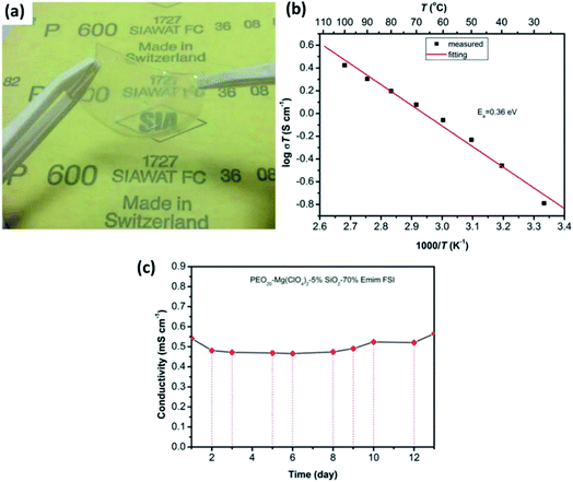 | ||
| Fig. 12 (a) Photograph of a gel-based polymer system with the composition of PEO20–Mg(ClO4)2–5% SiO2–70% EMIm, and the plots of ionic conductivity as a variable of (b) temperature and (c) time (in days) for the gel-based polymer. Reproduced from ref. 156 with permission, copyright 2017, Electrochemical Society. | ||
MgO is another passive filler that has been explored in the literature. MgO is classified as a passive filler because the Mg2+ migration barrier in MgO is extremely high.97 Therefore, Mg2+ transport across even one or two nanometers of MgO particles is unlikely at room temperature. Pandey et al.159 fabricated free-standing polymer composite thin films of MgO nanoparticles (<100 nm) uniformly distributed in 1 M Mg(ClO4)2 immobilized in PVDF-HFP. This combination led to high ionic conductivity of 8 × 10⁻³ S cm−1 at room temperature with the inclusion of 10 wt% MgO. The transference number for this composition was 0.44, and bulk conductivity seemed reasonably stable over a period of 160 h. However, the voltage stability was limited to 3.5 V for 10 wt% nanocomposite. In 2015, Shao et al.160 introduced a free-standing polymer composite film containing Mg(BH4)2 and PEO (1![[thin space (1/6-em)]](https://www.rsc.org/images/entities/char_2009.gif) :
:![[thin space (1/6-em)]](https://www.rsc.org/images/entities/char_2009.gif) 8 mass ratio) with 1 wt% MgO nanoparticles. Surface and cross-sectional SEM images of the film revealed homogeneity in the distribution of ceramic fillers and absence of porosity (Fig. 13(a) and (b), respectively). The thickness of the films was 300 μm (Fig. 13(b)). With a cell containing Chevrel-phase Mo6S8 as the cathode, magnesium metal as the anode, and the composite electrolyte, Shao et al.160 demonstrated the reversible (de)intercalation of magnesium at a sweep rate of 0.05 mV s−1 and showed 98% coulombic efficiency over 150 charge–discharge cycles at 100 °C (Fig. 13(c) and (d)). The difference in the onset potential for the magnesium plating and stripping was found to be as low as 0.2 V, which could imply faster kinetics. Further, the charge and discharge plateaus (Fig. 13(d)) were flat with overpotential of around 150 mV. It is noteworthy that the polymer composite did not contain any organic-based magnesium salt or ionic liquids. This possibility of magnesium intercalation using polymer composites was understood to have been aided by the dissociation of Mg(BH4)2 in the PEO matrix by the embedded MgO particles.
8 mass ratio) with 1 wt% MgO nanoparticles. Surface and cross-sectional SEM images of the film revealed homogeneity in the distribution of ceramic fillers and absence of porosity (Fig. 13(a) and (b), respectively). The thickness of the films was 300 μm (Fig. 13(b)). With a cell containing Chevrel-phase Mo6S8 as the cathode, magnesium metal as the anode, and the composite electrolyte, Shao et al.160 demonstrated the reversible (de)intercalation of magnesium at a sweep rate of 0.05 mV s−1 and showed 98% coulombic efficiency over 150 charge–discharge cycles at 100 °C (Fig. 13(c) and (d)). The difference in the onset potential for the magnesium plating and stripping was found to be as low as 0.2 V, which could imply faster kinetics. Further, the charge and discharge plateaus (Fig. 13(d)) were flat with overpotential of around 150 mV. It is noteworthy that the polymer composite did not contain any organic-based magnesium salt or ionic liquids. This possibility of magnesium intercalation using polymer composites was understood to have been aided by the dissociation of Mg(BH4)2 in the PEO matrix by the embedded MgO particles.
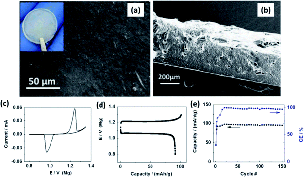 | ||
| Fig. 13 SEM images of (a) the surface and (b) cross-sectional image of Mg(BH4)2–MgO–PEO nanocomposite electrolyte; (c) cyclic voltammogram, (d) charge–discharge curves, and cycling stability of the cell made using the Mo6S8/Mg(BH4)2–MgO–PEO/Mg arrangement. Reproduced from ref. 160 with permission, copyright 2015, Elsevier. | ||
Till date, no significant advances in the fabrication of active-filler-embedded polymer composites have been achieved mainly due to the scarcity of highly conducting Mg2+-ion ceramic materials. However, a recent report on the addition of MgAl2O4 expected to act as an active filler in Mg(Tf)2-dissolved PVDF-HFP polymer system yielded high ionic conductivity (4 mS cm−1) in addition to affording a high transference number of 0.66 and electrochemical window of 3.3 V under the optimized composition. However, the contribution of magnesium aluminate on ion migration as compared to any other passive filler is yet to be fully understood. With the advent of a new generation of Mg2+-ion conductors, as discussed in earlier sections, there is renewed hope for a mechanically and chemically stable, highly conducting polymer–composite solid-state electrolyte. A comprehensive list of all the GPEs and ceramic–polymer-based composite electrolytes is provided in Table 1.
| Electrolyte system | Composition | Conductivity (mS cm−1) | Potential window (V) | Transfer number | References |
|---|---|---|---|---|---|
| Gel polymer electrolytes | Mg(Triflate)2–PVDF | 2.67 | 3.2 | 161 | |
| Mg(Triflate)2–PMMA | 0.42 | 3.3 | 0.55 | 145 | |
| Mg(NO3)2–PEO–PVP | 0.58 | 4 | 0.33 | 168 | |
| Mg(CH3COO)2–PEG | 1.07 × 10⁻³ | 140 | |||
| Mg[(CF3SO2)2N]2–PEO–PMA–PEGDE | 0.1 | 0.5 | 132 | ||
| Mg(Triflate)2–PVDF-HFP–EC + PC | 5.11 | 3.5 | 0.27 | 163 | |
| Mg(Triflate)2–PMMA–EC + DEC | 0.056 | 2.42 | 0.37 | 166 | |
| (Hexamethyldisilylamido)–MgCl2–PEO–THF | 5.2 × 10⁻³ | 1.6 | 130 | ||
| Mg(Triflate)2–Celgard | 0.17 | 137 | |||
| Mg(ClO4)2–PEG–borate ester | 1.25 × 10⁻⁴ | 0.51 | 139 | ||
| Mg(ClO4)2–PDE–PME–PEG–borate ester | 0.0726 | 0.36 | 138 | ||
| Mg(ClO4)2–PVA–PAN | 0.296 | 3.65 | 0.27 | 135 | |
| Mg(ClO4)2–PVA–PVP | 0.11 | 3.5 | 0.31 | 169 | |
| Mg(ClO4)2–PMMA–EC + PC | 3.3 | 0.39 | 164 | ||
| Mg(ClO4)2–β-PVDF–PC | 1.49 | 5.0 | 0.47 | 170 | |
| (MgTFSI)2–EMITfSI–PEO–PMA | 0.11 | 171 | |||
| Mg(AlCl2EtBu)2–PVDF–tetraglyme | 3.7 | 2.5 | 131 | ||
| EtMgBr–PEO–DBE | 0.1 | 1.3 | 129 | ||
| Mg(Triflate)2–EMITf–PVDF-HFP | 4.8 | 3.5 | 0.26 | 136 | |
| Mg(Triflate)2–EMITf–PVDF-HFP–succinonitrile | 4.0 | 4.1 | 167 | ||
| Mg(Triflate)2–BMIMTf–P(VdF-HFP) | 4.0 | 162 | |||
| Mg(Triflate)2–EMITf–PEO | 0.56 | 0.45 | 165 | ||
| Mg[(CF3SO2)N]2–EC + DMC–PEO–PMA | 2.8 | 133 | |||
| Mg(Triflate)2–PC + EC–PAN | 3.5 | 3.7 | 134 | ||
| MgCl2–Mg(BH4)2–PTHF_glass fibres | 0.476 | 2.5 | 0.73 | 147 | |
| Ceramic–polymer composite electrolytes | Mg(ClO4)2_fumed silica–PVDF-HFP | 11 | 3.5 | 0.28 | 157 |
| Mg(BH4)2_MgO–PEO | 2 | 160 | |||
| Mg(ClO4)2_SiO2–PVDF-HFP | 3.2 | 4.3 | 156 | ||
| MgClO4_MgO–PVDF-HFP | 6 | 3.5 | 0.44 | 159 | |
| Mg(CH3COO)2_TiO2–PEG | 0.0501 | 0.98 | 154 | ||
| Mg(Tf)2_MgAl2O4–PVDF-HFP | 4 | 3.3 | 0.66 | 172 |
3. Discussion
At present, one of the major challenges in obtaining an ideal solid-state inorganic magnesium-based electrolyte lies in the ionic conductivity at room temperature. Fig. 14 shows the Arrhenius plots of the ionic conductivities of various inorganic compounds and MOFs. The activation energies determined from the Arrhenius plots are also indicated in this figure. In practical terms, it is necessary that the materials exhibit ionic conductivities close to those of liquid electrolytes (around 1 mS cm−1). From the plot, it is evident that there is a scarcity of room-temperature magnesium-ion conductors. High temperature and low conductivity remain the norm for several of these compounds. The only exceptions remain Mg1.05(Zn0.4Al0.3Zr1.3)(PO4)3, MgSc2Se4, and MOFs, which show acceptable room-temperature conductivity. However, in several cases of aliovalent doping, one needs to be wary of the electronic contribution to the net conductivity, as evident from their very low activation energies (<0.1 eV). The electronic conductivity in several doped Mg0.5Zr2(PO4)3 compounds has not been covered well while studying their impedance characteristics. In the case of chalcogenides, the electronic conductivity overshadows their ionic characteristics and plagues their use as solid electrolytes. MOFs appear promising, but their compatibility with magnesium metal and high-potential cathodes remains to be explored.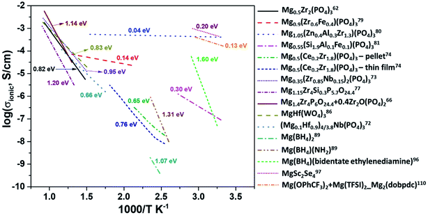 | ||
| Fig. 14 Arrhenius plots of ionic conductivity as a function of the inverse of temperature for several inorganic Mg2+-ion conductors. | ||
To identify the limiting factor of high Mg-ion conductivity at room temperature, we performed the following analysis under the theoretical framework of multi-excitation entropy and compared the ion transport properties of several classes of Mg and Na conductors. The Arrhenius relation (as shown in Fig. 14) between the ionic conductivity (σ) of crystalline ceramics and temperature (T) is expressed as below:
 | (1) |
 | (2) |
For a given system, a linear variation of log(prefactor) and activation energies of ion migration for a similar family of compounds can be expected based on eqn (2). Fig. 15 shows a plot of prefactors of NASICON-based pure and substituted Mg0.5Zr2(PO4)3 and borohydride-based systems as a function of their activation energies. An almost linear variation (Fig. 15) suggests that these compounds are in agreement with the Meyer–Neldel rule. The inverse of the slope from the linear fit reveals the magnitude of Δ. The extrapolated Δ values were 78 (±10) meV and 13 (±1) meV for phosphate- and borohydride-based magnesium conductors, respectively. For comparison, the prefactors (determined from earlier reported Arrhenius plots) of high-ionic-conducting sodium-based NASICON phosphates and NaBH4 families of compounds were plotted as a function of their activation energies.179–183 The Δ value obtained from the plots were found to be around 158 and 154 meV for the family of Na-based phosphates and hydrides, respectively, which are considerably higher in magnitude as compared to their Mg counterparts. These results suggest that either the phonon spectra of Mg compounds are substantially different or the interaction of lattice vibrations with Mg migration substantially varies when compared with those of their Na counterparts. The Meyer–Neldel plot calls for a tradeoff between the activation energy and prefactor in the design of improved Mg-ion conductors. Future research efforts should be directed toward improving the understanding of lattice dynamics to yield the much-yearned Mg-based solid-state electrolytes.
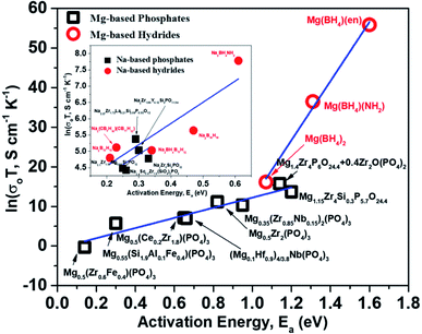 | ||
| Fig. 15 Plot of prefactors as a function of activation energies for Mg- and Na-based NASICON phosphates and hydrides; the linear fit is represented by the blue lines. | ||
4. Closing remarks
Rechargeable magnesium-ion batteries are at a critical point in our research for alternatives to lithium-ion batteries, with the emphasis on sustainability. Solid electrolytes could offer the best opportunity to propel magnesium-ion batteries to the top of energy technologies. This review considered the studies and understanding of solid electrolytes for magnesium-based rechargeable batteries from a materials perspective. Some of the important achievements and discoveries made in the field of solid-state electrolytes for magnesium-based batteries are shown in Fig. 16 in the form of a timeline. Solid Mg2+-ion-conducting electrolytes—categorized as inorganic ceramics, glasses, MOFs, polymers, and ceramic–polymer-based composites—have shown considerable promise, but with a pinch of salt. The low room-temperature ionic conductivities of inorganic ceramics and glasses are the first line of challenge that precludes their use in high-power applications. Although MgSc2Se4 exhibits one of the highest room-temperature ionic conductivities, the major hurdle of tapping the electronic conductivity needs to be addressed. Next, MOFs require further studies into their chemical and thermal stabilities against magnesium metal and high-potential cathodes. In addition, the tedious processing conditions for MOFs can become a deterrent when industrial-scale synthesis becomes a requirement. Oxides are a more economical option for solid electrolytes, and a derivative in the NASICON-based systems, namely, Mg0.5Si2(PO4)3, is the closest candidate with room-temperature ionic conductivity in the 10−6 S cm−1 range and electrochemical window of up to 3.2 V. As a side note, for a better understanding of the ionic diffusion process, concomitant detailed structural investigations to the ionic transport measurements are required. Researchers across the globe need to be encouraged to invest more in exploring the lattice structure to yield the much-yearned highly conducting Mg-based solid-state ceramic electrolytes. Polymers, on the other hand, that have been investigated have ionic conductivities close to those of their liquid counterparts, but they represent a different line of challenge: magnesium-metal compatibility and electrode–electrolyte interfacial resistance. On the other hand, recent reports on coating materials for cathodes and anodes in magnesium-ion batteries have opened up more avenues in the search for solid-state electrolytes as several of the binary, ternary, and quaternary compounds (including silicides, nitrides, borides, and oxides) exhibit low migration barriers.184 Canepa et al. demonstrated that nanosizing these coating materials could help achieving desirable ionic diffusion (depending on the C-rate) in the particle even if the migration barriers are large.185,186 This was further elaborated by identifying an Arrhenius relationship between the maximum migration barrier for high ionic diffusion and particle size. However, when these coating materials were transformed into solid electrolytes, nanosizing proved to be detrimental as it could lead to a large increase in the grain-boundary resistance, further impeding the ion transport process. The combination of low migration barrier for ionic transport, higher ionic conductivity, and better electrochemical stability, if achieved in these materials, could prove to be another breakthrough in the search for magnesium-ion-based solid-state electrolytes. Furthermore, the poor mechanical strength of solid electrolyte thin films limits the assembly only to flat cell configurations. With the present assembly protocol, based on thin-film technology, scaling up can be a challenge, too: large-sized batteries can truly become unaffordable. One school of thought to circumvent such interface issues is that in order to compete with incumbent batteries, solid-state batteries should use a “starved” electrolyte in the form of a solid pellet with a touch of liquid electrolyte so that the problems of electrode–electrolyte contact and power can be simultaneously addressed. Nevertheless, there is still a long way to go in order to realize high Mg2+-ion-conducting ceramics for use in all-solid-state batteries and to reach the heights of advancements achieved by lithium-based systems.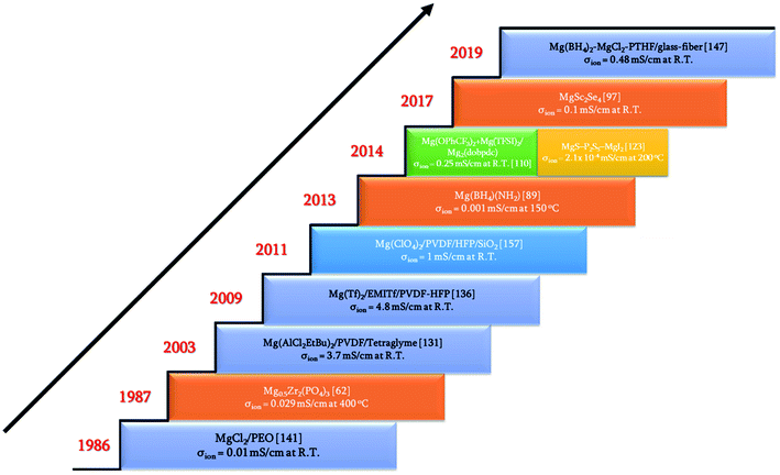 | ||
| Fig. 16 Timeline of some of the breakthroughs in the search for solid-state magnesium-ion conductors. | ||
Conflicts of interest
The authors declare no conflict of interest.Acknowledgements
This work was supported by Shanghai Sailing Program (Contract No. 18YF1411100) and National Natural Science Foundation of China (Contract No. 51801121). One of the authors, P. W. Jaschin, acknowledges China Postdoctoral Council for the fellowship provided under the Postdoctoral International Exchange scheme. P. W. Jaschin would also like to acknowledge Dr T. Prem Kumar for useful discussions and proof-reading.References
- C. C. Chan, Y. S. Wong, A. Bouscayrol and K. Chen, Proc. IEEE, 2009, 97, 603 Search PubMed.
- S. J. Skerlos and J. J. Winebrake, Energy Policy, 2010, 38, 705–708 CrossRef.
- B. G. Pollet, I. Staffell and J. L. Shang, Electrochim. Acta, 2012, 84, 235–249 CrossRef CAS.
- A. K. Shukla and T. Prem Kumar, J. Phys. Chem. Lett., 2013, 4, 551–555 CrossRef CAS PubMed.
- (a) J. Axsen and K. S. Kurani, Glob. Environ. Chang., 2013, 23, 70–80 CrossRef; (b) T.-R. Hsu, Proc. Green Energy and Systems Conf., Long Beach, CA, Nov. 5, 2013 Search PubMed.
- S. Manzetti and F. Mariasiu, Renew. Sustain. Energy Rev., 2015, 51, 1004–1012 CrossRef CAS.
- L. C. Casals, E. Martinez-Laserna, B. A. Garcia and N. Nieto, J. Clean. Prod., 2016, 127, 425–437 CrossRef.
- M. A. Hannana, M. M. Hoque, A. Mohamed and A. Ayob, Renew. Sustain. Energy Rev., 2017, 69, 771–789 CrossRef.
- C. Wu, W. Hua, Z. Zhang, B. Zhong, Z. Yang, G. Feng, W. Xiang, Z. Wu and X. Guo, Adv. Sci., 2018, 5, 1800519 CrossRef PubMed.
- C. Wu, Z. Zhang, Y. Tang, Z. Yang, Y. Li, B. Zhong, Z.-G. Wu, X. Guo and S.-X. Dou, ACS Appl. Mater. Interfaces, 2018, 10, 43740–43748 CrossRef CAS PubMed.
- C. Wu, Z.-G. Wu, X. Zhang, R. Rajagopalan, B. Zhong, W. Xiang, M. Chen, H. Li, T. Chen, E. Wang, Z. Yang and X. Guo, ACS Appl. Mater. Interfaces, 2017, 9, 43596–43602 CrossRef CAS PubMed.
- C. Zhao, L. Liu, X. Qi, Y. Lu, F. Wu, J. Zhao, Y. Yu, Y.-S. Hu and L. Chen, Adv. Energy Mater., 2018, 8, 1703012 CrossRef.
- P. G. Balakrishnan, R. Ramesh and T. Prem Kumar, J. Power Sources, 2006, 155, 401–414 CrossRef CAS.
- R. Marom, S. F. Amalraj, N. Leifer, D. Jacob and D. Aurbach, J. Mater. Chem., 2011, 21, 9938–9954 RSC.
- D. Lisbona and T. Snee, Process Saf. Environ. Prot., 2011, 89, 434–442 CrossRef CAS.
- J. Wen, Y. Yu and C. Chen, Mater. Express, 2012, 2, 197–212 CrossRef CAS.
- B. Diouf and R. Pode, Renewable Energy, 2015, 76, 375–380 CrossRef.
- N. Nitta, F. Wu, J. T. Lee and G. Yushin, Mater. Today, 2015, 18, 252–264 CrossRef CAS.
- S. Abada, G. Marlair, A. Lecocq, M. Petit, V. Sauvant-Moynot and F. Huet, J. Power Sources, 2016, 306, 178–192 CrossRef CAS.
- J.-L. Ma, F.-L. Meng, Y. Yu, D.-P. Liu, J.-M. Yan, Y. Zhang, X.-B. Zhang and Q. Jiang, Nat. Chem., 2019, 11, 64–70 CrossRef CAS PubMed.
- Y.-D. Xu, W. Xiang, Z.-G. Wu, C.-L. Xu, Y.-C. Li, X.-D. Guo, G.-P. Lv, X. Peng and B.-H. Zhong, Electrochim. Acta, 2018, 268, 358–365 CrossRef CAS.
- Y. -P. Deng, Z. -G. Wu, R. Liang, Y. Jiang, D. Luo, A. Yu and Z. Chen, Adv. Funct. Mater., 2019, 29, 1808522 CrossRef.
- L. Qiu, W. Xiang, W. Tian, C.-L. Xu, Y.-C. Li, Z.-G. Wu, T.-R. Chen, K. Jia, D. Wang, F.-R. He and X.-D. Guo, Nano Energy, 2019, 63, 103818 CrossRef CAS.
- F. Ding, W. Xu, G. L. Graff, J. Zhang, M. L. Sushko, X. Chen, Y. Shao, M. H. Engelhard, Z. Nie, J. Xiao, X. Liu, P. V. Sushko, J. Liu and J. G. Zhang, J. Am. Chem. Soc., 2013, 135, 4450–4456 CrossRef CAS PubMed.
- L. Gireaud, S. Grugeon, S. Laruelle, B. Yrieix and J. M. Tarascon, Electrochem. Commun., 2006, 8, 1639–1649 CrossRef CAS.
- R. S. Thompson, D. J. Schroeder, C. M. López, S. Neuhold and J. T. Vaughey, Electrochem. Commun., 2011, 13, 1369–1372 CrossRef CAS.
- J. Liu, Z. Bao
![[thin space (1/6-em)]](https://www.rsc.org/images/entities/char_2009.gif) , Y. Cui, E. J. Dufek
, Y. Cui, E. J. Dufek![[thin space (1/6-em)]](https://www.rsc.org/images/entities/char_2009.gif) , J. B. Goodenough
, J. B. Goodenough![[thin space (1/6-em)]](https://www.rsc.org/images/entities/char_2009.gif) , P. Khalifah, Q. Li
, P. Khalifah, Q. Li![[thin space (1/6-em)]](https://www.rsc.org/images/entities/char_2009.gif) , B. Y. Liaw, P. Liu, A. Manthiram
, B. Y. Liaw, P. Liu, A. Manthiram![[thin space (1/6-em)]](https://www.rsc.org/images/entities/char_2009.gif) , Y. S. Meng
, Y. S. Meng![[thin space (1/6-em)]](https://www.rsc.org/images/entities/char_2009.gif) , V. R. Subramanian, M. F. Toney, V. V. Viswanathan, M. S. Whittingham
, V. R. Subramanian, M. F. Toney, V. V. Viswanathan, M. S. Whittingham![[thin space (1/6-em)]](https://www.rsc.org/images/entities/char_2009.gif) , J. Xiao, W. Xu
, J. Xiao, W. Xu![[thin space (1/6-em)]](https://www.rsc.org/images/entities/char_2009.gif) , J. Yang, X.-Q. Yang and J.-G. Zhang, Nat. Energy, 2019, 4, 180–186 CrossRef CAS.
, J. Yang, X.-Q. Yang and J.-G. Zhang, Nat. Energy, 2019, 4, 180–186 CrossRef CAS. - U. Kasavajjula, C. Wang and A. J. Appleby, J. Power Sources, 2007, 163, 1003–1039 CrossRef CAS.
- W.-J. Zhang, J. Power Sources, 2011, 196, 13–24 CrossRef CAS.
- A. R. Kamali and D. J. Fray, Rev. Adv. Mater. Sci., 2011, 27, 14–24 CAS.
- A. M. Chockla, K. C. Klavetter, C. B. Mullins and B. A. Korgel, Chem. Mater., 2012, 24, 3738–3745 CrossRef CAS.
- Y. Xu, Q. Liu, Y. Zhu, Y. Liu, A. Langrock, M. R. Zachariah and C. Wang, Nano Lett., 2013, 13, 470–474 CrossRef CAS PubMed.
- M. Ge, X. Fang, J. Rong and C. Zhou, Nanotechnology, 2013, 24, 422001 CrossRef CAS PubMed.
- C. Wang, H. Wu, Z. Chen, M. T. McDowell, Y. Cui and Z. Bao, Nat. Chem., 2013, 5, 1042–1048 CrossRef CAS PubMed.
- Y. Zhao, X. Li, B. Yan, D. Li, S. Lawes and X. Sun, J. Power Sources, 2015, 274, 869–884 CrossRef CAS.
- B. Luo, T. Q. D. Ye, L. Wang and L. Zhi, Nano Energy, 2016, 22, 232–240 CrossRef CAS.
- Y. Cui and C. M. Lieber, Science, 2001, 291, 851–853 CrossRef CAS PubMed.
- O. Crowther and A. C. West, J. Electrochem. Soc., 2008, 155, A806–A811 CrossRef CAS.
- D. Aurbach, Y. Cohen and M. Moshkovich, Electrochem. Solid-State Lett., 2001, 4, A113–A116 CrossRef CAS.
- M. Masaki, J. Power Sources, 2011, 196, 7048–7055 CrossRef.
- C. Ling, D. Banerjee and M. Matsui, Electrochim. Acta, 2012, 76, 270–274 CrossRef CAS.
- R. Davidson, A. Verma, D. Santos, F. Hao, C. Fincher, S. Xiang, J. V. Buskirk, K. Xie, M. Pharr, P. Mukherjee and S. Banerjee, ACS Energy Lett., 2019, 4, 375–376 CrossRef CAS.
- T. D. Gregory, R. J. Hoffman and R. C. Winterton, J. Electrochem. Soc., 1990, 137, 775–780 CrossRef CAS.
- T. Ichitsubo, T. Adachi, S. Yagi and T. Doi, J. Mater. Chem., 2011, 21, 11764–11772 RSC.
- D. Imamura, M. Miyayama, M. Hibino and T. Kudo, J. Electrochem. Soc., 2003, 150, A753–A758 CrossRef CAS.
- D. Imamura and M. Miyayama, Solid State Ionics, 2003, 173, 173–180 CrossRef.
- D. Aurbach, Z. Lu, A. Schechter, Y. Gofer, H. Gizbar, R. Turgeman, Y. Cohen, M. Moshkovich and E. Levi, Nature, 2000, 407, 724–727 CrossRef CAS PubMed.
- Y. Liang, R. Feng, S. Yang, H. Ma, J. Liang and J. Chen, Adv. Mater., 2011, 23, 640–643 CrossRef CAS PubMed.
- S. Yang, D. Li, T. Zhang, Z. Tao and J. Chen, J. Phys. Chem. C, 2012, 116, 1307–1312 CrossRef CAS.
- Y. Liu, L. Jiao, Q. Wu, J. Du, Y. Zhao, Y. Si, Y. Wang and H. Yuan, J. Mater. Chem. A, 2013, 1, 5822–5826 RSC.
- C. Ling and F. Mizuno, Chem. Mater., 2013, 25, 3062–3071 CrossRef CAS.
- X. Sun, P. Bonnick, V. Duffort, M. Liu, Z. Rong, K. A. Persson, G. Ceder and L. F. Nazar, Energy Environ. Sci., 2016, 9, 2273–2277 RSC.
- Y. NuLi, J. Yang, J. Wang and Y. Li, J. Phys. Chem. C, 2009, 113, 12594–12597 CrossRef CAS.
- L. Suo, O. Borodin, T. Gao, M. Olguin, J. Ho, X. Fan, C. Luo, C. Wang and K. Xu, Science, 2015, 350, 938–943 CrossRef CAS PubMed.
- D. Aurbach, Y. Gofer, A. Schechter, O. Chusid, H. Gizbar, Y. Cohen, M. Moshkovich and R. Turgeman, J. Power Sources, 2001, 97–98, 269–273 CrossRef CAS.
- D. Aurbach, I. Weissman, Y. Gofer and E. Levi, Chem. Rec., 2003, 3, 61–74 CrossRef CAS PubMed.
- Y. Gofer, N. Pour and D. Aurbach, Electrolytic solutions for rechargeable magnesium batteries, in Lithium Batteries: Advanced Technologies and Applications, Wiley-VCH, Weinheim, 2013, pp. 328–345 Search PubMed.
- J. Muldoon, C. B. Bucur, A. G. Oliver, T. Sugimoto, M. Matsui, H. S. Kim, G. D. Allred, J. Zajicekb and Y. Kotanie, Energy Environ. Sci., 2014, 5, 5941–5950 RSC.
- X.-B. Cheng, R. Zhang, C.-Z. Zhao, F. Wei, J.-G. Zhang and Q. Zhang, Adv. Sci., 2016, 3, 1500213 CrossRef.
- S. J. An, J. Li, C. Daniel, D. Mohanty, S. Nagpure and D. L. Wood, Carbon, 2016, 105, 52 CrossRef CAS.
- C. B. Bucur, Challenges of a rechargeable magnesium battery, Springer Nature, Cham, Switzerland, 2018 Search PubMed.
- S. Ikeda, M. Takahashi, J. Ishikawa and K. Ito, Solid State Ionics, 1987, 23, 125–129 CrossRef CAS.
- A. Kazakos-Kijowski, S. Komarneni, D. Agrawal and R. Roy, Mater. Res. Bull., 1988, 23, 1177–1184 CrossRef CAS.
- E. R. Gobechiya, M. V. Sukhanov, V. I. Pet’kov and Y. K. Kabalov, Crystallogr. Rep., 2008, 53, 53–59 CrossRef CAS.
- M. Adamu and G. M. Kale, J. Phys. Chem. C, 2016, 120, 17909–17915 CrossRef CAS.
- N. Imanaka, Y. Okazaki and G. Adachi, J. Mater. Chem., 2000, 10, 1431–1435 RSC.
- J. J. Didisheim, E. Prince and B. J. Wuensch, Solid State Ionics, 1986, 18–19, 944–958 CrossRef CAS.
- H. Kohler and H. Schulz, Mater. Res. Bull., 1985, 20, 1461–1471 CrossRef CAS.
- K. Namura, S. Ikeda and K. Ito, Bull. Chem. Soc. Jpn., 1992, 65, 3221–3227 CrossRef.
- K. Nakano, Y. Noda, N. Tanibata, M. Nakayama, K. Kajihara and K. Kanamura, RSC Adv., 2019, 9, 12590–12595 RSC.
- Z. Zhang, Q. Zhang, J. Shi, Y. S. Chu, X. Yu, K. Xu, M. Ge, H. Yan, W. Li, L. Gu, Y.-S. Hu, H. Li, X.-Q. Yang, L. Chen and X. Huang, Adv. Energy Mater., 2017, 7, 1601196 CrossRef.
- S. Tamura, M. Yamane, Y. Hoshino and N. Imanaka, J. Solid State Chem., 2016, 235, 7–11 CrossRef CAS.
- K. Kajihara, H. Nagano, T. Tsujita, H. Munakata and K. Kanamura, J. Electrochem. Soc., 2017, 164, A2183–A2185 CrossRef CAS.
- B. Liang, V. Keshishian, S. Liu, E. Yi, D. Jia, Y. Zhou, J. Kieffer, B. Ye and R. M. Laine, Electrochim. Acta, 2018, 272, 144–153 CrossRef CAS.
- Z. A. Halim, S. B. R. S. Adnan and N. S. Mohamed, Ceram. Int., 2016, 42, 4452–4461 CrossRef CAS.
- Z. A. Halim, S. B. R. S. Adnan, F. M. Salleh and N. S. Mohamed, J. Magnesium Alloys, 2017, 5, 439–447 CrossRef CAS.
- K. Nomura, S. Ikeda, K. Ito and H. Einaga, Chem. Lett., 1992, 21, 1897–1900 CrossRef.
- N. Imanaka, Y. Okazaki and G. Adachi, Ionics, 2001, 7, 440–446 CrossRef CAS.
- N. K. Anuar, S. B. R. S. Adnan, M. H. Jaafar and N. S. Mohamed, Ionics, 2016, 22, 1125–1133 CrossRef CAS.
- N. K. Anuar and N. S. Mohamed, J. Sol-Gel Sci. Technol., 2016, 80, 249–258 CrossRef CAS.
- N. A. Dzulkurnain, N. A. Mustaffa and N. S. Mohamed, J. New Mater. Electrochem. Syst., 2017, 20, 135–140 CrossRef.
- N. Imanaka, Y. Okazaki and G. Adachi, Electrochem. Solid-State Lett., 2000, 3, 327–329 CrossRef CAS.
- H. Takahashi and H. Takamura, Mater. Trans., 2012, 53, 932–935 CrossRef CAS.
- H. Takahashia and H. Takamura, Key Eng. Mater., 2012, 508, 291–299 Search PubMed.
- M. Sulaiman, N. C. Su and N. S. Mohamed, Ionics, 2017, 23, 443–452 CrossRef CAS.
- A. Omote, S. Yotsuhashi, Y. Zenitani and Y. Yamada, J. Am. Ceram. Soc., 2011, 94, 2285–2288 CrossRef CAS.
- M. Matsuo, H. Oguchi, T. Sato, H. Takamura, E. Tsuchida, T. Ikeshoji and S. Orimo, J. Alloys Compd., 2013, 580, S98–S101 CrossRef CAS.
- A. Unemoto, M. Matsuo and S.-I. Orimo, Adv. Funct. Mater., 2014, 24, 2267–2279 CrossRef CAS.
- S. Higashi, K. Miwa, M. Aoki and K. Takechi, Chem. Commun., 2013, 50, 1320–1322 RSC.
- R. Mohtadi, M. Matsui, T. S. Arthur and S.-J. Hwang, Angew. Chem., Int. Ed., 2012, 51, 9780–9783 CrossRef CAS PubMed.
- R. L. Ruyet, R. Berthelot, E. Salager, P. Florian, B. Fleutot and R. Janot, J. Phys. Chem. C, 2019, 123, 10756–10763 CrossRef.
- D. Wohlmuth, V. Epp, P. Bottke, I. Hanzu, B. Bitschnau, I. Letofsky-Papst, M. Kriechbaum, H. Amenitsch, F. Hofer and M. Wilkening, J. Mater. Chem. A, 2014, 2, 20295–20306 RSC.
- A. Dunst, V. Epp, I. Hanzu, S. A. Freunberger and M. Wilkening, Energy Environ. Sci., 2014, 7, 2739–2752 RSC.
- M. Wilkening, V. Epp, A. Feldhoff and P. Heitjans, J. Phys. Chem. C, 2008, 112, 9291–9300 CrossRef CAS.
- P. W. Jaschin and K. B. R. Varma, J. Appl. Phys., 2017, 121, 094101 CrossRef.
- E. Roedern, R.-S. Kühnel, A. Remhof and C. Battaglia, Sci. Rep., 2017, 7, 46189 CrossRef CAS.
- P. Canepa, S.-H. Bo, G. S. Gautam, B. Key, W. D. Richards, T. Shi, Y. Tian, Y. Wang, J. Li and G. Ceder, Nat. Commun., 2017, 8, 1759 CrossRef.
- Z. Rong, R. Malik, P. Canepa, G. S. Gautam, M. Liu, A. Jain, K. Persson and G. Ceder, Chem. Mater., 2015, 27, 6016–6021 CrossRef CAS.
- G. S. Gautam, P. Canepa, A. Urban, S.-H. Bo and G. Ceder, Chem. Mater., 2017, 29, 7918–7930 CrossRef.
- P. Canepa, G. S. Gautam, D. Broberg, S.-H. Bo and G. Ceder, Chem. Mater., 2017, 29, 9657–9667 CrossRef CAS.
- L.-P. Wang, Z. Zhao-Karger, F. Klein, J. Chable, T. Braun, A. R. Schür, C.-R. Wang, Y.-G. Guo and M. Fichtner, ChemSusChem, 2019, 12, 2286–2293 CrossRef CAS PubMed.
- J. R. Long and O. M. Yaghi, Chem. Soc. Rev., 2009, 38, 1213–1214 RSC.
- Z. Q. Wang and S. M. Cohen, Chem. Soc. Rev., 2009, 38, 1315–1329 RSC.
- M. Eddaoudi, J. Kim, N. Rosi, D. Vodak, J. Wachter, M. O'Keeffe and O. M. Yaghi, Science, 2002, 295, 469–472 CrossRef CAS PubMed.
- F. Stallmach, S. Groger, V. Kunzell, J. Karger, O. M. Yaghi, M. Hesse and U. Muller, Angew. Chem., Int. Ed., 2006, 45, 2123–2126 CrossRef CAS PubMed.
- N. Yanai, T. Uemura, S. Horike, S. Shimomura and S. Kitagawa, Chem. Commun., 2011, 47, 1722–1724 RSC.
- A. Morozan and F. Jaouen, Energy Environ. Sci., 2012, 5, 9269–9290 RSC.
- L. Wang, Y. Han, X. Feng, J. Zhou, P. Qi and B. Wang, Coord. Chem. Rev., 2016, 307, 361–381 CrossRef CAS.
- H. Zhang, J. Nai, L. Yu and X. W. Lou, Joule, 2017, 1, 77–107 CrossRef CAS.
- M. L. Aubrey, R. Ameloot, B. M. Wiers and J. R. Long, Energy Environ. Sci., 2014, 7, 667–671 RSC.
- S. S. Park, Y. Tulchinsky and M. Dincă, J. Am. Chem. Soc., 2017, 139, 13260–13263 CrossRef CAS PubMed.
- E. M. Miner, S. S. Park and M. Dincă, J. Am. Chem. Soc., 2019, 141, 4422–4427 CrossRef CAS PubMed.
- J. A. Hurd, R. Vaidhyanathan, V. Thangadurai, C. I. Ratcliffe, I. L. Moudrakovski and G. K. H. Shimizu, Nat. Chem., 2009, 1, 705–710 CrossRef CAS PubMed.
- P. Ramaswamy, N. E. Wong, B. S. Gelfand and G. K. H. Shimizu, J. Am. Chem. Soc., 2015, 137, 7640–7643 CrossRef CAS PubMed.
- H. B. Wu and X. W. Lou, Sci. Adv., 2017, 3, 9252 CrossRef PubMed.
- Y. Lu, L. Wang, J. Cheng and J. B. Goodenough, Chem. Commun., 2012, 48, 6544–6546 RSC.
- T. Minami, J. Non-Cryst. Solids, 1985, 73, 273–284 CrossRef CAS.
- F. Gan, J. Non-Cryst. Solids, 1992, 140, 184–193 CrossRef CAS.
- A. Pradel and M. Ribes, Mater. Sci. Eng., B, 1989, 3, 45–46 CrossRef.
- J. C. Dyre, P. Maass, B. Roling and D. L. Sidebottom, Rep. Prog. Phys., 2009, 72, 046501 CrossRef.
- F. Mizuno, A. Hayashi, K. Tadanaga and M. Tatsumisago, Adv. Mater., 2005, 17, 918–921 CrossRef CAS.
- K. Minami, A. Hayashi and M. Tatsumisago, J. Am. Ceram. Soc., 2011, 94, 1779–1783 CrossRef CAS.
- T. Yamanaka, A. Hayashi, A. Yamauchi and M. Tatsumisago, Solid State Ionics, 2014, 262, 601–603 CrossRef CAS.
- Y. Nishitani, S. Shibata, T. Tsujita, O. Tetsuyuki and A. Omote, ECS Meeting Abstr. MA2016-02, 2016, p. 676 Search PubMed.
- J. Y. Song, Y. Y. Wang and C. C. Wan, J. Power Sources, 1999, 77, 183–197 CrossRef CAS.
- A. M. Stephan, Eur. Polym. J., 2006, 42, 21–42 CrossRef.
- C. Berthier, W. Gorecki, M. Minier, M. B. Armand, J. M. Chabagno and P. Rigaud, Solid State Ionics, 1983, 11, 91–95 CrossRef CAS.
- S.-K. Jeong, Y.-K. Jo and N.-J. Jo, Electrochim. Acta, 2006, 52, 1549–1555 CrossRef CAS.
- C. Liebenow, Electrochim. Acta, 1998, 43, 1253–1256 CrossRef CAS.
- C. Liebenow and S. Mantey, J. Solid State Electrochem., 2003, 7, 313–316 CrossRef CAS.
- O. Chusid, Y. Gofer, H. Gizbar, Y. Vestfrid, E. Levi and D. Aurbach, Adv. Mater., 2003, 15, 627–630 CrossRef CAS.
- M. Morita, N. Yoshimoto, S. Yakushiji and M. Ishikawa, Electrochem. Solid State Lett., 2001, 4, A177–A179 CrossRef CAS.
- N. Yoshimoto, S. Yakushiji, M. Ishikawa and M. Morita, Electrochim. Acta, 2003, 48, 2317–2322 CrossRef CAS.
- G. G. Kumar and N. Munichandraiah, Solid State Ionics, 2000, 128, 203–210 CrossRef CAS.
- R. Manjuladevi, M. Thamilselvan, S. Selvasekarapandian, R. Mangalam, M. Premalatha and S. Monisha, Solid State Ionics, 2017, 308, 90–100 CrossRef CAS.
- G. P. Pandey and S. A. Hashmi, J. Power Sources, 2009, 187, 627–634 CrossRef CAS.
- S. Ikeda, Y. Mori, Y. Furuhashi, H. Masuda and O. Yamamoto, J. Power Sources, 1999, 81–82, 720–723 CrossRef CAS.
- M. Saito, H. Ikuta, Y. Uchimoto, M. Wakihara, S. Yokoyama, T. Yabe and M. Yamamoto, J. Electrochem. Soc., 2003, 150, A477–A483 CrossRef CAS.
- M. Saito, H. Ikuta, Y. Uchimoto, M. Wakihara, S. Yokoyama, T. Yabe and M. Yamamoto, J. Phys. Chem. B, 2003, 107, 11608–11614 CrossRef CAS.
- A. R. Polu, V. Causin, R. Kumar and R. Neppalli, J. Korean Phys. Soc., 2011, 59, 114–118 CrossRef CAS.
- L. L. Yang, A. R. McGhie and G. C. Farrington, J. Electrochem. Soc., 1986, 133, 1380–1385 CrossRef CAS.
- A. Patrick, M. Glasse, R. Latham and R. Linford, Solid State Ionics, 1986, 18, 1063–1067 CrossRef.
- C. Liebenow, Solid State Ionics, 2000, 136, 1211–1214 CrossRef.
- D. Li, X. Ji, X. Gong, F. Tsai, Q. Zhang, L. Yao, T. Jiang, R. K. Y. Li, H. Shi, S. Luan and D. Shi, J. Power Sources, 2019, 423, 349–357 CrossRef CAS.
- G. G. Kumar and N. Munichandraiah, Electrochim. Acta, 1999, 44, 2663–2666 CrossRef CAS.
- M. Morita, N. Yoshimoto, S. Yakushiji and M. Ishikawa, Electrochem. Solid State Lett., 2001, 4, A177–A179 CrossRef CAS.
- A. Du, H. Zhang, Z. Zhang, J. Zhao, Z. Cui, Y. Zhao, S. Dong, L. Wang, X. Zhou and G. Cui, Adv. Mater., 2019, 31, 1805930 CrossRef.
- L. C. Merrill, H. O. Ford and J. L. Schaefer, ACS Appl. Energy Mater., 2019, 2, 6355–6363 CrossRef CAS.
- J. L. Thelen, S. Inceoglu, N. R. Venkatesan, N. G. Mackay and N. P. Balsara, Macromolecules, 2016, 49, 9139–9147 CrossRef CAS.
- R. C. Agrawal and G. P. Pandey, J. Phys. D: Appl. Phys., 2008, 41, 223001 CrossRef.
- M. Dirican, C. Yan, P. Zhu and X. Zhang, Mater. Sci. Eng., R, 2019, 136, 27–46 CrossRef.
- E. Bekaert, L. Buannic, U. Lassi, A. Llordés and J. Salminen, Electrolytes for Li- and Na-ion batteries: concepts, candidates, and the role of nanotechnology, in Emerging Nanotechnologies in Rechargeable Energy Storage Systems, ed. L. Rodriguez and N. Omar, Elsevier, Boston, 2017, pp. 1–43 Search PubMed.
- Z. D. Hood, H. Wang, Y. Li, A. S. Pandian, M. P. Paranthaman and C. Liang, Solid State Ionics, 2015, 283, 75–80 CrossRef CAS.
- A. R. Polu, R. Kumar, K. V. Kumar and N. K. Jyothi, AIP Conf. Proc., 2013, 1512, 996–997 CrossRef CAS.
- M. Sundar and S. Selladurai, Ionics, 2006, 12, 281–286 CrossRef CAS.
- S. Song, M. Kotobuki, F. Zheng, Q. Li, C. Xu, Y. Wang, W. Dong, Z. Li, N. Hu and L. Lu, J. Electrochem. Soc., 2017, 164, A741–A743 CrossRef CAS.
- G. P. Pandey, R. C. Agrawal and S. A. Hashmi, J. Solid State Electrochem., 2011, 15, 2253–2264 CrossRef CAS.
- J.-S. Oh, J.-M. Ko and D.-W. Kim, Electrochim. Acta, 2004, 50, 903–906 CrossRef CAS.
- G. P. Pandey, R. C. Agrawal and S. A. Hashmi, J. Power Sources, 2009, 190, 563–572 CrossRef CAS.
- Y. Shao, N. N. Rajput, J. Hu, M. Hu, T. Liu, Z. Wei, M. Gu, X. Deng, S. Xu, K. S. Han, J. Wang, Z. Nie, G. Li, K. R. Zavadil, J. Xiao, C. Wang, W. A. Henderson, J.-G. Zhang, Y. Wang, K. T. Mueller, K. Persson and J. Liu, Nano Energy, 2015, 12, 750–759 CrossRef CAS.
- G. G. Kumar and N. Munichandraiah, J. Power Sources, 2001, 102, 46–54 CrossRef CAS.
- S. Ramesh, S.-C. Lu and I. Vankelecom, J. Phys. Chem. Solids, 2013, 74, 1380–1386 CrossRef CAS.
- A. Rosdia, N. H. Zainol and Z. Osman, AIP Conf. Proc., 2016, 1711, 050003 CrossRef.
- Z. Osman, N. H. Zainol, S. M. Samin, W. G. Chong, K. B. Md Isa, L. Othman, I. Supa'at and F. Sonsudin, Electrochim. Acta, 2014, 131, 148–153 CrossRef CAS.
- Y. Kumar, S. A. Hashmi and G. P. Pandey, Electrochim. Acta, 2011, 56, 3864–3873 CrossRef CAS.
- S. N. Asmara, M. Z. Kufian, S. R. Majid and A. K. Arof, Electrochim. Acta, 2011, 57, 91–97 CrossRef CAS.
- J. Sharma and S. A. Hashmi, Bull. Mater. Sci., 2018, 41, 147 CrossRef.
- K. M. Anilkumar, B. Jinisha, M. Manoj and S. Jayalekshmi, Eur. Polym. J., 2017, 89, 249–262 CrossRef CAS.
- M. Ramaswamy, T. Malayandi, S. Subramanian, J. Srinivasalu and M. Rangaswamy, Ionics, 2017, 23, 1771–1781 CrossRef CAS.
- R. Singh, S. Janakiraman, M. Khalifa, S. Anandhan, S. Ghosh, A. Venimadhav and K. Biswas, J. Electroanal. Chem., 2019, 851, 113417 CrossRef CAS.
- M. Morita, T. Shirai, N. Yoshimoto and M. Ishikawa, J. Power Sources, 2005, 139, 351–355 CrossRef CAS.
- J. Sharma and S. Hashmi, Polym. Compos., 2019, 40, 1295–1306 CrossRef CAS.
- A. Dalvi, N. P. Reddy and S. C. Agarwal, Solid State Commun., 2012, 152, 612–615 CrossRef CAS.
- A. Yelon, B. Movaghar and R. S. Crandall, Rep. Prog. Phys., 2006, 69, 1145–1194 CrossRef CAS.
- D. P. Almond and A. R. West, Solid State Ionics, 1986, 18, 1105–1109 CrossRef.
- D. P. Almond and A. R. West, Solid State Ionics, 1987, 23, 27–35 CrossRef CAS.
- K. L. Ngai, Solid State Ionics, 1998, 105, 231–235 CrossRef CAS.
- S. Muy, J. C. Bachman, H.-H. Chang, L. Giordano, F. Maglia, S. Lupart, P. Lamp, W. G. Zeier and Y. Shao-Horn, Chem. Mater., 2018, 30, 5573–5582 CrossRef CAS.
- T. J. Udovic, M. Matsuo, W. S. Tang, H. Wu, V. Stavila, A. V. Soloninin, R. V. Skoryunov, O. A. Babanova, A. V. Skripov, J. J. Rush, A. Unemoto, H. Takamura and S.-I. Orimo, Adv. Mater., 2014, 26, 7622–7626 CrossRef CAS.
- Z. Zhang, Y. Shao, B. Lotsch, Y.-S. Hu, H. Li, J. Janek, L. F. Nazar, C.-W. Nan, J. Maier, M. Armand and L. Chen, Energy Environ. Sci., 2018, 11, 1945–1976 RSC.
- J.-J. Kim, K. Yoon, I. Park and K. Kang, Small Methods, 2017, 1, 1700219 CrossRef.
- Q. Ma, M. Guin, S. Naqash, C.-L. Tsai, F. Tietz and O. Guillon, Chem. Mater., 2016, 28, 4821–4828 CrossRef CAS.
- S. Song, H. M. Duong, A. M. Korsunsky, N. Hu and L. Lu, Sci. Rep., 2016, 6, 32330 CrossRef CAS PubMed.
- T. Chen, G. Ceder, G. S. Gautam and P. Canepa, Front. Chem., 2019, 7, 24 CrossRef CAS PubMed.
- P. Canepa, G. S. Gautam, D. C. Hannah, R. Malik, M. Liu, K. G. Gallagher, K. A. Persson and G. Ceder, Chem. Rev., 2017, 117, 4287–4341 CrossRef CAS PubMed.
- T. Chen, G. S. Gautam and P. Canepa, Chem. Mater., 2019, 31, 8087–8099 CrossRef CAS.
| This journal is © The Royal Society of Chemistry 2020 |


