Nickel(II)-modified covalent-organic framework film for electrocatalytic oxidation of 5-hydroxymethylfurfural (HMF)†
Meng
Cai
 ,
Sha
Ding
 ,
Bradley
Gibbons
 ,
Xiaozhou
Yang
 ,
Matthew C.
Kessinger
 and
Amanda J.
Morris
 *
*
Department of Chemistry, Virginia Polytechnic Institute and State University, 1040 Drillfield Drive, Blacksburg, Virginia 24061, USA. E-mail: ajmorris@vt.edu
First published on 22nd October 2020
Abstract
Electrochemical oxidation of 5-hydroxymethylfurfural (HMF) is a promising synthetic route for 2,5-furandicarboxylic acid (FDCA) production. Here, we prepared a nickel(II)-modified covalent-organic framework (COF) film TpBpy-Ni@FTO for HMF electrooxidation. With a high conversion of HMF (96%), TpBpy-Ni@FTO afforded a 58% FDCA yield. This work underlines the great potential of COF-based materials in electrocatalysis.
Biomass is a renewable energy source for the production of fuels and other high value chemicals and materials. Among various biomass-derived building blocks, 2,5-furandicarboxylic acid (FDCA) has drawn extensive attention. In 2004, FDCA was identified as one of the twelve bio-based priority building blocks for building a sustainable chemistry industry by the U.S. Department of Energy (DOE).1 FDCA serves as a promising substitute for terephthalic acid, an important monomer in the production of polyesters, including polyethylene terephthalate (PET) and polybutyleneterephthalate (PBT). In addition, a number of value-added derivatives such as 2,5-dihydroxymethylfuran and 2,5-bis(aminomethyl)tetrahydrofuran can be obtained from FDCA via simple chemical transformations.1 Therefore, the production of FDCA and its derivatives can lead to high economic value.
FDCA can be produced via oxidation of 5-hydroxymethylfurfural (HMF), which itself is an important intermediate that can be generated from dehydration of C6 sugars.2 There are two possible reaction pathways for HMF oxidation (Fig. 1).3 HMF can first be converted into either 2,5-diformylfuran (DFF) or 5-hydroxymethyl-2-furan-carboxylic acid (HMFCA), and then oxidized into 5-formyl-2-furancarboxylic acid (FFCA), and ultimately FDCA.
In many previous studies, FDCA was produced by aerobic oxidation of HMF, which usually occurred under high oxygen/air pressure and elevated temperature, with precious metals as catalysts (Au, Pt, Pd, Ru, etc.).4–7 The harsh reaction conditions and high cost of previous metals are not favorable in large-scale production. Instead of aerobic oxidation, electrochemical oxidation of HMF serves as an alternative route. Compared to aerobic oxidation, electrochemical oxidation is driven by an applied potential. As a result, high pressures of oxygen and the addition of chemical oxidants are unnecessary. In an early study on electrochemical oxidation of HMF, nickel oxide/hydroxide was used as a catalyst to achieve 71% yield of FDCA.8 This study suggests the possibility of using non-precious metals as catalysts in electrochemical oxidation of HMF. Recently, different non-previous metals such as MnOx,9 cobalt-metalloid alloys,10 NiOOH,11etc. have been successfully used as electrocatalysts for HMF oxidation.
Compared to homogeneous catalysts, heterogeneous catalysts are easier for recycle and reuse. As a result, many catalysts were deposited onto conductive substrates. Among various materials, covalent-organic frameworks (COFs), a new class of porous organic polymers constructed with light-weight elements (C, H, N, B, etc.) serve as a promising platform for catalyst immobilization.12 Their highly porous structure allows for efficient diffusion of reactants and products, rendering each incorporated catalyst catalytically accessible. Additionally, the good thermal and chemical stability enable COFs to survive changing reaction environments. These unique features make COFs an ideal platform material for incorporation of catalysts. In this study, we incorporated Ni(II) acetate into a two-dimensional (2D) COF, TpBpy (Tp = triformylphloroglucinol, Bpy = 5,5′-diamino-2,2′-bipyridine), as an electrocatalyst for HMF oxidation. The as-prepared TpBpy-Ni film afforded a nearly unity HMF conversion and a FDCA yield of 58%. To the best of our knowledge, this is the first example of using COF-based catalyst for HMF electrochemical oxidation.
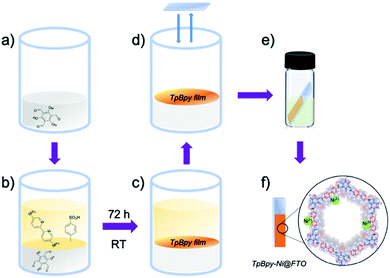
TpBpy films were prepared via an interfacial crystallization method following a reported procedure.13 A two-phase interface was formed between an organic layer containing triformylphloroglucinol (Tp) (Fig. 2a) and an aqueous layer containing 5,5′-diamino-2,2′-bipyridine (Bpy) and p-toluenesulfonic acid (PTSA) (Fig. 2b). The TpBpy film gradually crystallized at the interface after 72 h under room temperature (Fig. 2c). After the top aqueous layer was removed, a fluorine-doped tin oxide (FTO) glass slide was used to transfer the COF film onto the FTO by simple “stamping”. The resulting TpBpy film on FTO was then post-synthetically modified by soaking in a nickel acetate solution to yield a nickel(II)-doped TpBpy-Ni film immobilized on FTO, denoted as TpBpy-Ni@FTO.
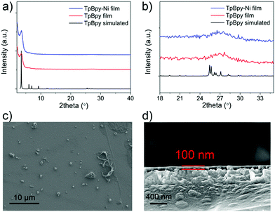
Powder X-ray diffraction (PXRD) was used to characterize as-prepared TpBpy film (Fig. 3). A major peak at ∼3.5° corresponding to the 100 plane was observed, in agreement with simulated patterns. A broad peak was observed at ∼27°, corresponding to the 001 plane. This peak suggested the π–π stacking between COF layers. TpBpy-Ni film prepared via post-synthetic modification (PSM) of TpBpy exhibited consistent PXRD patterns with TpBpy, indicating that the structure of TpBpy was well retained after PSM. TpBpy-Ni showed a high Brunauer–Emmett–Teller (BET) surface area of 278 m2 g−1 (Fig. S1, ESI†), suggesting its porous structure that is advantageous for heterogeneous catalysis. Scanning electron microscopy (SEM) images of TpBpy-Ni showed a uniform thin film with a thickness of ∼100 nm. It is noted that some small spherical layers were observed on top of the thin film. Similar observations have also been reported for films prepared by interfacial polymerization.14 These spherical features were ascribed to result from the heat generation during the crystallization reaction at the interface. Energy dispersive spectroscopy (EDS) mapping study (Fig. S2, ESI†) showed that Ni was distributed over the entire film, suggesting the uniform incorporation of Ni.
Cyclic voltammetry (CV) was used to investigate the electrochemical behaviour of TpBpy-Ni film (Fig. 4) in 0.1 M LiClO4 solution (pH 13). For comparison, a bare FTO and an unmodified TpBpy film immobilized on FTO (TpBpy@FTO) were also characterized under same conditions. In the absence of HMF, no significant peaks were observed from the bare FTO or TpBpy@FTO (Fig. S3, ESI†). A pair of redox peaks with a halfwave potential of 1.50 V (vs. RHE) was seen from TpBpy-Ni@FTO (Fig. 4), corresponding to Ni(II)/(III) oxidation/reduction. A significant current take-off beginning from ∼1.60 V (vs. RHE) was also observed. This was ascribed to water oxidation catalyzed by Ni(II) in TpBpy-Ni@FTO.15 In the presence of 5 mM HMF, both the bare FTO and TpBpy@FTO exhibited insignificant difference as compared to in the absence of HMF, suggesting no catalytic activity toward HMF oxidation. In contrast, TpBpy-Ni@FTO demonstrated an increase in current beginning at a potential coincided with Ni(II) oxidation. During the reverse scan, a prominent oxidation current was observed. Such current crossover is commonly observed when the oxidation of formed intermediate, in this case DFF, HMFCA, or FFCA, requires less potential than the initial oxidation of HMF.16,17 This is indeed the case, as evidenced by a lower onset potential for HMFCA oxidation (Fig. S4, ESI†). To further elucidate the nature of the oxidation peak observed from TpBpy-Ni@FTO in the presence of HMF, CVs of TpBpy-Ni@FTO in solutions with different HMF concentrations (0.1–1 mM) were collected. As seen in Fig. S5 (ESI†), the oxidation current increased as HMF concentration increased, further verifying that the oxidation peak at ∼1.55 V (vs. RHE) was due to HMF oxidation. Moreover, a linear dependence of peak current and HMF concentration was obtained, suggesting that HMF oxidation rate is linearly dependent on its concentration.
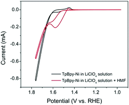 | ||
| Fig. 4 CVs of TpBpy-Ni@FTO in the absence (black line) and in the presence (red line) of 5 mM HMF in 0.1 M LiClO4 solution (pH = 13). | ||
As an electrocatalyst, efficient charge transfer is necessary. In previous studies, a redox hopping mechanism was applied to explain charge transfer in polymers and metal–organic frameworks (MOFs) doped with redox-active centers.18–20 It is proposed that in redox hopping, electrons can hop from one redox-active site to another, accompanied by the diffusion of counterions to balance the charge. Similarly, in TpBpy-Ni, the incorporated Ni sites can serve as redox-active sites that potentially allow for redox hopping. To investigate the charge transfer property in TpBpy-Ni@FTO, CVs at different scan rates (5–1000 mV s−1) were conducted (Fig. 5). The anodic and cathodic peak currents both increased when the scan rate increased. In redox hopping, the diffusion of electrons and counterions should lead to a diffusion-controlled process that follows the well-known Randles–Sevcik equation, which demonstrates that there is a linear relationship between the current and the square root of the scan rate.20 However, for TpBpy-Ni@FTO, a linear relationship between the current and the scan rate was obtained (Fig. S6, ESI†). Such a current-scan rate relationship was observed and discussed previously by the Morris group.21 When the coverage of active sites is low, there are fewer effective pathways (i.e. site to site hopping pathways) for redox hopping to occur. As a result, the oxidation/reduction peak currents mainly result from Ni sites close to the electrode surface. This was further verified by the low electroactive Ni coverage, (5 ± 2)%, as calculated from the ratio of Ni sites responsive during controlled potential electrolysis (CPE) to the total amount of Ni determined by ICP-MS.
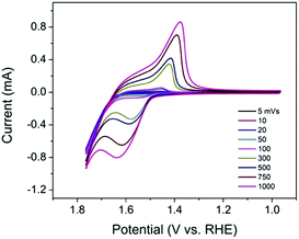 | ||
| Fig. 5 CVs of TpBpy-Ni@FTO in 0.1 M LiClO4 solution (pH 13) at different scan rates (5–1000 mV s−1). | ||
The performance of TpBpy-Ni@FTO as an electrocatalyst for HMF oxidation was evaluated by CPE. A constant potential of 1.55 V (vs. RHE) was applied onto TpBpy-Ni@FTO in an electrochemical cell containing 0.5 mM HMF. A total amount of 2.9 C charge was passed, which is the theoretical stoichiometric amount of charge needed to fully convert HMF into FDCA (see ESI† for details). High-performance liquid chromatography (HPLC) was used to analyze HMF oxidation products during CPE (Fig. 6). As mentioned previously, there are two possible pathways for HMF oxidation. HMFCA was observed from HPLC while no DFF was detected throughout the entire electrolysis (Fig. S7, ESI†), indicating that the HMF oxidation pathway for TpBpy-Ni@FTO follows HMF → HMFCA → FFCA → FDCA. This pathway is consistent with previous study conducted at high pH values (≥13).22 As an increasing amount of charge was passed, a decrease in HMF peak intensity was observed, with an increase in FFCA and FDCA (Fig. S9, ESI†). After passing 2.9 C of charge, 96% HMF was converted, with a combination of FDCA (58% yield) and FFCA (34% yield) as products (Table S2, ESI†). The turn-over number (TON) and turn-over frequency (TOF) were (1.6 ± 0.6) × 103 and (6 ± 2) × 10−3 s−1. X-ray Photoelectron Spectroscopy (XPS) analysis of pre- and post-catalysis TpBpy-Ni@FTO films showed that no significant peak shift from Ni was observed (Fig. S10, ESI†). Additionally, only trace amount of Ni (∼0.3%) was detected in the post-catalysis solution by ICP-MS (inductively coupled plasma mass spectrometer). These results indicate the good stability of the TpBpy-Ni film.
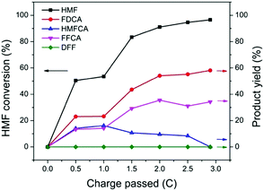 | ||
| Fig. 6 HMF conversion and yields of products after passing 0, 0.5, 1, 1.5, 2, 2.5, 2.9 C. Each data point is average of three tests (see Table S1, ESI†). | ||
The full conversion of HMF into FDCA requires three reaction steps: HMF → HMFCA (step 1), HMFCA → FFCA (step 2), and FFCA → FDCA (step 3). It is noted that during HMF oxidation, the concentration of HMFCA over the entire reaction period was small. Additionally, the observation of HMFCA was often accompanied by the observation of FFCA. These results suggest that the consumption of HMFCA, i.e. step 2, was faster than step 1. To offer insights into which step, step 1 or step 3, is the rate-limiting process, a study of the kinetics of the two steps was conducted. The oxidation of 0.5 mM HMF and 0.5 mM FFCA were analyzed by HPLC over a 40 min reaction period. During this initial reaction period, it was hypothesized that only a small amount of product was generated, and therefore concentration gradients had little impact on reaction rates. The reaction rate of step 3 can be determined by the increase in FDCA concentration over time. As previously mentioned, during the oxidation of HMF, both HMFCA and FFCA (the oxidation product of step 2) were immediately detected. Given that step 2 is faster than 1, step 1 should be the limiting process during the conversion of HMF into a mixture of HMFCA and FFCA. Therefore, the decrease in HMF concentration was plotted to represent the reaction rate of step 1. As shown in Fig. 7, FDCA production in step 3 (rate = 1.22 × 10⁻⁹ M s−1) was much slower than HMF consumption (rate = 4.58 × 10⁻⁸ M s−1) in step 1. Since the concentration of two reactants are the same, the comparison between their reaction rates can serve as a proxy for the reaction rate constant – assuming similar potentials for activation. Therefore, step 3 was identified as the rate-limiting process during HMF oxidation. These results are further supported by the linear sweep voltammetry (LSV) analysis (Fig. S4, ESI†). As mentioned earlier, the onset potential for HMFCA oxidation (step 2) is lower than that of step 1, suggesting that step 2 is thermodynamically more efficient. With similar onset potentials, FFCA oxidation (step 3) showed smaller current than HMF oxidation in step 1, implying that step 3 is kinetically slower than step 1. Therefore, future efforts should be on the development of catalysts that are highly efficient in FFCA oxidation.
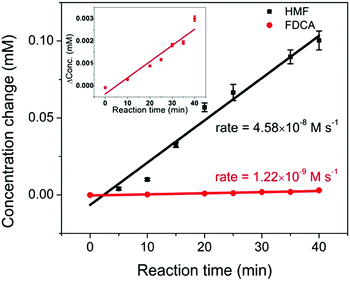 | ||
| Fig. 7 The comparison of reaction rates of 0.5 mM HMF oxidation (black) and 0.5 mM FFCA oxidation (red, enlarged plot is shown in the inset), under an applied potential of 1.55 V vs. RHE for 40 min. | ||
In this work, a Ni(II) modified COF, TpBpy-Ni@FTO, was prepared and used as an electrocatalyst for HMF oxidation in alkaline solution. The HMF oxidation pathway was identified following HMF → HMFCA → FFCA → FDCA. Upon a constant potential applied, a high conversion of HMF (96%) was achieved, with FFCA (34% yield) and FDCA (58% yield) as products. The last step, oxidation of FFCA into FDCA was identified as the rate-determining step. While the FDCA yield is not ideal, the TpBpy-Ni@FTO provides a platform for optimization of COF catalysts for biomass conversion.
This material is based upon work supported by the National Science Foundation under Grant No. 1551964. We thank Dr Mehdi Ashraf-Khorassani for his help with HPLC. We thank Dr Xu Feng and the Surface Analysis Laboratory at Virginia Tech for the XPS analysis supported by the National Science Foundation under Grant No. CHE-1531834.
This work was performed in part at the Nanoscale Characterization and Fabrication Laboratory, which is supported by the Virginia Tech National Center for Earth and Environmental Nanotechnology Infrastructure (NanoEarth), a member of the National Nanotechnology Coordinated Infrastructure (NNCI), supported by NSF (ECCS 1542100 and ECCS 2025151). We thank Dr. Elizabeth Cantando for her help with TEM JEOL2100.
Conflicts of interest
There are no conflicts to declare.Notes and references
-
T. Werpy and G. Petersen, Top value added chemicals from biomass: volume I—results of screening for potential candidates from sugars and synthesis gas, National Renewable Energy Lab., Golden, CO (US), 2004 Search PubMed
.
- A. A. Rosatella, S. P. Simeonov, R. F. Frade and C. A. Afonso, Green Chem., 2011, 13, 754–793 RSC
.
- P. Verdeguer, N. Merat and A. Gaset, J. Mol. Catal., 1993, 85, 327–344 CrossRef CAS
.
- Y. Y. Gorbanev, S. Kegnæs and A. Riisager, Top. Catal., 2011, 54, 1318 CrossRef CAS
.
- H. Ait Rass, N. Essayem and M. Besson, ChemSusChem, 2015, 8, 1206–1217 CrossRef CAS
.
- Y. Y. Gorbanev, S. K. Klitgaard, J. M. Woodley, C. H. Christensen and A. Riisager, ChemSusChem, 2009, 2, 672–675 CrossRef CAS
.
- S. E. Davis, L. R. Houk, E. C. Tamargo, A. K. Datye and R. J. Davis, Catal. Today, 2011, 160, 55–60 CrossRef CAS
.
- G. Grabowski, J. Lewkowski and R. Skowroński, Electrochim. Acta, 1991, 36, 1995 CrossRef CAS
.
- S. R. Kubota and K. S. Choi, ChemSusChem, 2018, 11, 2138–2145 CrossRef CAS
.
- J. Weidner, S. Barwe, K. Sliozberg, S. Piontek, J. Masa, U.-P. Apfel and W. Schuhmann, Beilstein J. Org. Chem., 2018, 14, 1436–1445 CrossRef
.
- B. J. Taitt, D.-H. Nam and K.-S. Choi, ACS Catal., 2018, 9, 660–670 CrossRef
.
- S. Kandambeth, K. Dey and R. Banerjee, J. Am. Chem. Soc., 2018, 141, 1807–1822 CrossRef
.
- K. Dey, M. Pal, K. C. Rout, S. Kunjattu H, A. Das, R. Mukherjee, U. K. Kharul and R. Banerjee, J. Am. Chem. Soc., 2017, 139, 13083–13091 CrossRef CAS
.
- S. Karan, Z. Jiang and A. G. Livingston, Science, 2015, 348, 1347–1351 CrossRef CAS
.
- H. B. Aiyappa, J. Thote, D. B. Shinde, R. Banerjee and S. Kurungot, Chem. Mater., 2016, 28, 4375–4379 CrossRef CAS
.
- A. Velázquez-Palenzuela, F. Centellas, J. A. Garrido, C. Arias, R. M. Rodríguez, E. Brillas and P.-L. Cabot, J. Power Sources, 2011, 196, 3503–3512 CrossRef
.
- J. R. Miller and P. Simon, Sci. Mag., 2008, 321, 651–652 CAS
.
- S. Lin, P. M. Usov and A. J. Morris, Chem. Commun., 2018, 54, 6965–6974 RSC
.
- S. R. Ahrenholtz, C. C. Epley and A. J. Morris, J. Am. Chem. Soc., 2014, 136, 2464–2472 CrossRef CAS
.
- M. Cai, Q. R. Loague, J. Zhu, S. Lin, P. M. Usov and A. J. Morris, Dalton Trans., 2018, 47, 16807–16812 RSC
.
- S. Lin, Y. Pineda-Galvan, W. A. Maza, C. C. Epley, J. Zhu, M. C. Kessinger, Y. Pushkar and A. J. Morris, ChemSusChem, 2017, 10, 514–522 CrossRef CAS
.
- K. R. Vuyyuru and P. Strasser, Catal. Today, 2012, 195, 144–154 CrossRef CAS
.
Footnote |
| † Electronic supplementary information (ESI) available. See DOI: 10.1039/d0cc02206c |
| This journal is © The Royal Society of Chemistry 2020 |


