3D hollow reduced graphene oxide foam as a stable host for high-capacity lithium metal anodes†
Pengcheng
Yao
,
Qiyuan
Chen
,
Yu
Mu
,
Jie
Liang
,
Xiuqiang
Li
,
Xin
Liu
,
Yang
Wang
,
Bin
Zhu
* and
Jia
Zhu
 *
*
National Laboratory of Solid State Microstructures, College of Engineering and Applied Sciences, School of Physics, Key Laboratory of Intelligent Optical Sensing and Integration, and Collaborative Innovation Center of Advanced Microstructures, Nanjing University, Nanjing 210093, P. R. China. E-mail: jiazhu@nju.edu.cn; binzhu@nju.edu.cn
First published on 19th December 2018
Abstract
Lithium is considered to be a promising anode material for high-energy batteries on account of its high capacity and low potential. However, both dendritic lithium formation and very large volume changes during cycling severely restrict its practical applications. Herein, we propose a 3D hollow reduced graphene oxide foam as a host for prestoring lithium. Aside from the advantages of accommodating volume change and lowering the local current density, this unique structure also provides a large host space, one that enables lithium prestorage both outside and inside the reduced graphene oxide, in which Li occupies ∼85 weight percent of the whole composite electrode. The anode showed a corresponding gravimetric specific capacity as high as 3280 mA h g−1. Moreover, it showed highly stable cycling with small hysteresis at 1 mA cm−2 in the carbonate electrolyte. When it was assembled into a full cell with NCM (Li(Ni1/3Co1/3Mn1/3)O2) as the cathode, the resulting battery showed good cycling performance, having displayed 92% capacity retention (128.2 mA h g−1) and appealing power capacity (82 mA h g−1 at 5C) after being cycled 200 times at 0.3C.
Introduction
To meet the increasing demand for portable electronics and electric vehicles,1 it is urgent to develop lithium (Li) batteries with higher energy densities since commercial lithium-ion batteries (LIB) are approaching their capacity limits.2–7 Recently, much attention has been focused on the Li metal anode because of its critical importance for next-generation high-performance energy storage systems. Its high capacity (3860 mA h g−1) and low potential (−3.04 V vs. standard hydrogen electrode) make Li the most promising anode material for Li-S and Li-air batteries.8–10 However, Li dendrite formation and very large volume changes during cycling severely hinder its applications.11–16 Continuous efforts have been made to figure out the mechanism of Li deposition and tackle the aforementioned problems.17–20 These previous strategies mainly included (1) exploiting electrolyte additives or a new electrolyte recipe to stabilize solid electrolyte interface (SEI) formation,10,21–25 (2) developing a solid electrolyte to prevent Li dendrite penetration,26–29 and (3) engineering an artificial SEI to inhibit dendrite growth.3,30–34 Despite these approaches having to some extent relieved Li dendrite problems, the infinite volumetric change of Li deposition because of “hostless” Li plating/stripping remains a severe challenge.35 To address this problem, it is necessary to build a host for prestoring Li metal. Though electrodepositing Li in some 3D current collector hosts in advance is an option,18 this approach is always accompanied by uneven Li deposition and inefficient assembly. Thermal infusion of Li into host materials is a prominent strategy to prestore Li. Lin et al. reported that molten Li could be infused into reduced graphene oxide (rGO), which effectively accommodates the volume change of Li deposition.35 Chi et al. proposed that Ni foam is a good host for Li infusion, and the obtained Li/Ni composite anode demonstrated stable electrochemical cycling.36 These studies with better performances of longer cycling stability and higher coulombic efficiency have indicated that Li infusion into a host is a promising method. However, compared with bulk Li metal anode, the 3D metal host/scaffolds for Li infusion not only occupy a very great space and weight, lowering the specific capacity, but also exhibit uneven surfaces towards the separator, easily leading to short circuits. It still remains a challenge to rationally search for a stable host for thermal infusion due to the poor wettability of liquefied Li and the instability of hosts under a high-temperature environment.Herein, we demonstrated the ability of hollow 3D rGO foam to serve as a stable host for prestoring Li through the thermal infusion method. This structural design has several advantages: (i) the rGO foam framework offers a stable host for Li plating/stripping,37,38 efficiently diminishing the volumetric change of Li;39 (ii) rGO is a good lithiophilic material for uniform Li infusion and deposition;35,40 (iii) the formed hollow space inside rGO caused by etching Ni can also accept infused Li, increasing the weight percentage of active Li in the whole electrode, equivalently increasing the specific capacity; and (iv) the rGO framework without Ni makes the surface relatively uniform and supple. The formed Li/rGO composite material serving as an electrode showed stable cycling, even after more than 60 cycles in a symmetric cell at a current density of 1 mA cm−2. And when it was assembled into a full cell with NCM as the cathode, it was observed to afford good cycling performance (128.2 mA h g−1 after 200 cycles) and superb rate performance (82 mA h g−1 at 5C).
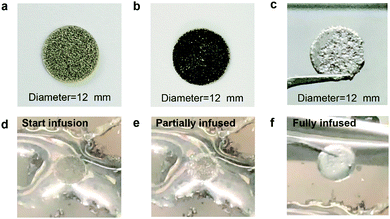
Fig. S1 (ESI†) shows a schematic diagram of the process used to fabricate the Li/rGO composite anode. The hollow 3D rGO foam was prepared by using the GO dispersion coating method with 3D nickel (Ni) foam as a template. The average thickness of the Ni foam was 0.5 mm. First, the Ni foam was immersed in the prepared GO dispersion and dried at 200 °C on a hotplate to yield uniformly coated GO/Ni foam. Second, the obtained GO/Ni foam structure was soaked in a mixture of sulphuric acid (H2SO4) (20 vol%) and hydrogen peroxide (H2O2) solution (1 vol%) for 10 min to etch Ni and produce a freestanding and hollow GO foam that could store more Li metal. Third, the etched GO/Ni foam was annealed under argon and 3% hydrogen gas mixture flow to produce 3D rGO foam. Finally, fresh Li metal was melted at 400 °C on a hotplate, and the rGO foam was then put in contact with the molten surface. Li started to infuse through the structure, covering both the inner and outer surfaces of the rGO foam and finally filled the 3D hollow structure (Fig. 1f). Fig. 1d–f show the Li infusion process, which can be controlled by changing the duration of contact of rGO/Ni foam with molten Li, clearly indicating the lithiophilic property of the obtained hollow rGO foam (Supplementary video, ESI†). Fig. 1a shows the 3-D hollow structure of the Ni foam used as a template. Meanwhile, Fig. 1b shows the uniform coating of GO. The final structure of the Li/rGO composite anode is shown in Fig. 1c, and was obtained by infusion of the melted Li into the rGO foam template. The average weights of Ni foam/rGO before and after infusion were 18.1 mg and 120.5 mg, respectively. The Li metal accounted for 85 wt% of the total anode. The high mass ratio of the Li metal can be attributed to the light weight and porous structure of rGO and etched Ni foam where the mass of the framework only took up ∼15 wt% of the whole electrode. As far as we know, this low weight value was only a bit higher than that of pure rGO host (∼8 wt%),30 and far below those of other works. Therefore, this specific choice of the carbon-based host material offers the possibility of fabricating high-performance Li anodes with high energy density.
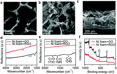
The rGO foam before melting Li was first characterized by performing scanning electron microscopy (SEM). As shown in Fig. 2a, GO sheets were uniformly coated on the surface of the Ni foam. Also, GO foam was observed to keep its 3D hollow structure after the etching treatment, and the maintenance of this structure helped improve both the ionic conductivity and the capacity to store Li metal. Fig. 2b shows an SEM image for Li/rGO foam after infusion, with molten Li infused through the structure, having covered both the inner and outer surfaces of the rGO foam and having filled the 3D hollow structure. A view of a cross-section of the Li/rGO foam (Fig. 2c) further revealed that the 3D hollow structure was filled with Li and the wall boundaries coated with Li metal. And the foam still retained its structure after the infusion. It is worth mentioning that after Li infusion, the Li/rGO composite anode exhibited much better mechanical strength than did both the Li metal and Ni foam for the purpose of being handled for cell assembly. To investigate the effect of the annealing process on the GO/Ni foam, Fourier-transform infrared spectroscopy (FTIR) and X-ray photoelectron spectroscopy (XPS) tests were conducted. As shown in Fig. 2d and e, while GO/Ni foam itself yielded three small peaks at 1733 cm−1, 1585 cm−1 and 1245 cm−1, corresponding to the vibrations of C![[double bond, length as m-dash]](https://www.rsc.org/images/entities/char_e001.gif) O, C
O, C![[double bond, length as m-dash]](https://www.rsc.org/images/entities/char_e001.gif) C and C–O, respectively, these three peaks were not observed for the rGO/Ni foam, indicating that the GO was indeed chemically reduced. The successful preparation of rGO was also clearly indicated using XPS (Fig. 2f): the area of the XPS oxygen (O) peak of the rGO/Ni foam was much smaller than that of the GO/Ni foam. The ratio of C
C and C–O, respectively, these three peaks were not observed for the rGO/Ni foam, indicating that the GO was indeed chemically reduced. The successful preparation of rGO was also clearly indicated using XPS (Fig. 2f): the area of the XPS oxygen (O) peak of the rGO/Ni foam was much smaller than that of the GO/Ni foam. The ratio of C![[thin space (1/6-em)]](https://www.rsc.org/images/entities/char_2009.gif) :
:![[thin space (1/6-em)]](https://www.rsc.org/images/entities/char_2009.gif) O was calculated to be 2.70
O was calculated to be 2.70![[thin space (1/6-em)]](https://www.rsc.org/images/entities/char_2009.gif) :
:![[thin space (1/6-em)]](https://www.rsc.org/images/entities/char_2009.gif) 1 for the rGO/Ni foam and 1.96
1 for the rGO/Ni foam and 1.96![[thin space (1/6-em)]](https://www.rsc.org/images/entities/char_2009.gif) :
:![[thin space (1/6-em)]](https://www.rsc.org/images/entities/char_2009.gif) 1 for the GO/Ni foam, again reflecting the reduction of GO.
1 for the GO/Ni foam, again reflecting the reduction of GO.
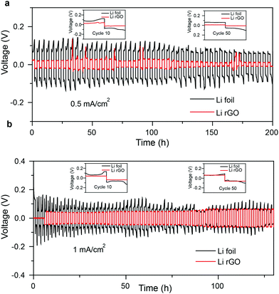
To evaluate the electrochemical stability of the Li/rGO composite anode, Li/rGO|Li/rGO symmetric cells were assembled with Li/Li cells as control samples. Fig. 3 shows the voltage hysteresis of the cells for 50 cycles at two different current densities, specifically 0.5 and 1 mA cm−2, but with the same area capacity of 1 mA h cm−2. As shown in Fig. 3a, under a current density of 0.5 mA cm−2, the Li/rGO composite electrode exhibited more stable voltage profiles with smaller hysteresis than did bare Li foils. The inset figures show magnified views of the 10th and 50th cycles of the 3-D Li/rGO symmetric cells. Compared with bare Li electrodes, Li/rGO maintained a flat voltage platform at both the charging and discharging process throughout the whole cycling. Also, no obvious increases in hysteresis were found all along the line. On the other hand, bare Li foil electrodes showed fluctuating voltage profiles at the stripping and plating process. According to previous reports,24 this result was due to the formation of an unstable SEI on the surface of the Li electrode. Meanwhile, these fluctuations can cause dendrite formation and result in poor stability of the electrodes.
The same conclusions were reached from the data collected when the current density was increased to 1 mA cm−2 (Fig. 3b) and 5 mA cm−2 (Fig. S5, ESI†). That is, this confined rGO foam framework offers a stable host for Li plating/stripping, efficiently relieving the volumetric change of Li. The 3-D rGO framework also makes the surface relatively uniform and supple, which suppress dendrite growth. These advantages make Li/rGO a better electrode than bare Li foil.
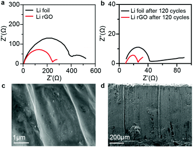
To measure the change in the impedance during cycling and reveal the mechanism of the highly reduced polarization and stable cycling performance of the Li/rGO composite anode, electrochemical impedance spectroscopy (EIS) analysis was conducted on symmetric cells before cycling (Fig. 4a) and after 120 cycles (Fig. 4b). In the corresponding Nyquist plots, the semicircle at the high frequency represents the interfacial resistance at the SEI and the charge-transfer resistance at the electrode/electrolyte interface. The Li foils showed a relatively large interfacial resistance of ∼410 Ω before cycling. This result was due to the oxide layer on the Li surface.35 After 120 cycles, the interfacial resistance decreased to a much lower value of ∼45 Ω, due to the collapse of the SEI layer and the formation of Li dendrites, which significantly increased the surface area.36 In contrast, the Li rGO composite anode had a constantly low interfacial resistance of ∼230 Ω before cycling and ∼25 Ω after 120 cycles. This phenomenon revealed that a greater electrode stability and easier Li stripping/plating kinetics can be achieved by using 3-D Li rGO than by using a bare Li foil. Also, SEM was used to characterize the morphological change of the Li/rGO electrode resulting from cycling (Fig. 4c and d). While irregular deposition and dendrites were clearly observed on the surface of the bare Li anode (Fig. S2, ESI†), neither dendrites nor defects were observed on the surface of Li/rGO electrode, indicating that the Li/rGO electrode can suppress dendrite growth and achieve a superior cycling performance.
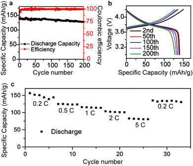
To further examine the electrochemical performance of the Li/rGO composite anode, cells a with Li(Ni1/3Co1/3 Mn1/3)O2 cathode (NCM 111), commercial electrolyte (LiPF6 in EC) and Li/rGO composite anode were assembled. The surface density of the active material of NCM 111 was about 2.4 mg cm−2 and all the battery tests were operated at 25 °C. The cells were cycled between 4.2 V and 3.0 V at 0.1C for three cycles first, followed by 0.3C for 70 cycles. The discharge capacity was initially 140 mA h g−1, and 128.2 mA h g−1 after 200 cycles (Fig. 5a). The specific capacity was higher than that using Li metal as the anode, which was ∼125 mA h g−1 between 3.0 and 4.2 V (Fig. S3, ESI†). Fig. 5b illustrates the flat voltage profiles of the NCM 111|Li/rGO full cell at different cycles, confirming its cycling stability. Fig. 5c presents the rate performance, where the specific capacity can be seen to reach 150, 125, 115, 103 and 82 mA h g−1 at different current densities of 0.2, 0.5, 1, 2 and 5C, respectively, which indicates the reasonable power capacities of the Li/rGO composite anode cell.
Conclusions
In summary, we successfully prepared an Li/rGO composite material as an anode. The rGO foam framework offers a stable host for Li plating/stripping, efficiently relieving the volumetric change of Li. The formed hollow space inside rGO caused by etching Ni was shown to accept infused Li, with Li metal accounting for 85 wt% of the total composite electrode. The Li/rGO anode was also shown to exhibit stable cycling in a symmetric cell at a current density of 1 mA cm−2. When assembled into a full cell with NCM as the cathode, this anode was found to afford good cycling performance (128.2 mA h g−1 after 200 cycles) and superb rate performance (82 mA h g−1 at 5C). All of these results showed that the Li/rGO composite anodes have a great potential to satisfy the high energy density and safety requirements for next-generation lithium batteries.Conflicts of interest
There are no conflicts of interest to declare.Acknowledgements
We acknowledge the micro-fabrication center of National Laboratory of Solid State Microstructures (NLSSM) for technical support. This work is jointly supported by the National Key Research and Development Program of China (No. 2017YFA0205700) and the State Key Program for Basic Research of China (No. 2015CB659300), the National Natural Science Foundation of China (No. 21805132, 11574143, 11874211, 11621091, 61735008), the Natural Science Foundation of Jiangsu Province (No. BK20180341) and the Fundamental Research Funds for the Central Universities (No. 021314380135, 021314380128).References
- Y. Li, X. Li, Z. Wang, H. Guo, T. Li, K. Meng and J. Wang, Mater. Chem. Front., 2018, 2, 1822–1828 RSC.
- W. Xu, J. L. Wang, F. Ding, X. L. Chen, E. Nasybutin, Y. H. Zhang and J. G. Zhang, Energy Environ. Sci., 2014, 7, 513–537 RSC.
- B. Zhu, Y. Jin, X. Hu, Q. Zheng, S. Zhang, Q. Wang and J. Zhu, Adv. Mater., 2017, 29, 1603755 CrossRef PubMed.
- G. Lv, B. Zhu, X. Li, C. Chen, J. Li, Y. Jin, X. Hu and J. Zhu, ACS Appl. Mater. Interfaces, 2017, 9, 44452–44457 CrossRef CAS PubMed.
- J. Wang, H. Tang, H. Wang, R. Yu and D. Wang, Mater. Chem. Front., 2017, 1, 414–430 RSC.
- Q. Wei, M.-R. Gao, Y. Li, D. Zhang, S. Wu, Z. Chen and Y. Sun, Mater. Chem. Front., 2018, 2, 1441–1448 RSC.
- Y. Liu, X. Yan, J. Lan, Y. Yu, X. Yang and Y. Lin, Mater. Chem. Front., 2017, 1, 1331–1337 RSC.
- M. S. Whittingham, Proc. IEEE, 2012, 100, 1518–1534 CAS.
- S. Choudhury, Z. Tu, S. Stalin, D. Vu, K. Fawole, D. Gunceler, R. Sundararaman and L. A. Archer, Angew. Chem., Int. Ed. Engl., 2017, 56, 13070–13077 CrossRef CAS PubMed.
- D. C. Lin, Y. Y. Liu and Y. Cui, Nat. Nanotechnol., 2017, 12, 194–206 CrossRef CAS PubMed.
- Q. Cheng, L. Wei, Z. Liu, N. Ni, Z. Sang, B. Zhu, W. Xu, M. Chen, Y. Miao, L. Q. Chen, W. Min and Y. Yang, Nat. Commun., 2018, 9, 2942 CrossRef PubMed.
- K. Xu, Chem. Rev., 2014, 114, 11503–11618 CrossRef CAS PubMed.
- K. Xu, Chem. Rev., 2004, 104, 4303–4417 CrossRef CAS.
- M. J. Zachman, Z. Tu, S. Choudhury, L. A. Archer and L. F. Kourkoutis, Nature, 2018, 560, 345–349 CrossRef CAS PubMed.
- X. B. Cheng, T. Z. Hou, R. Zhang, H. J. Peng, C. Z. Zhao, J. Q. Huang and Q. Zhang, Adv. Mater., 2016, 28, 2888–2895 CrossRef CAS PubMed.
- S. Liu, A. Wang, Q. Li, J. Wu, K. Chiou, J. Huang and J. Luo, Joule, 2018, 2, 184–193 CrossRef CAS.
- L. Fan, H. L. Zhuang, W. Zhang, Y. Fu, Z. Liao and Y. Lu, Adv. Energy Mater., 2018, 8, 1703360 CrossRef.
- Q. Li, S. Zhu and Y. Lu, Adv. Funct. Mater., 2017, 27, 1606422 CrossRef.
- A. Wang, X. Zhang, Y.-W. Yang, J. Huang, X. Liu and J. Luo, Chem, 2018, 4, 2192–2200 CAS.
- Y. Liu, Y.-K. Tzeng, D. Lin, A. Pei, H. Lu, N. A. Melosh, Z.-X. Shen, S. Chu and Y. Cui, Joule, 2018, 2, 1595–1609 CrossRef CAS.
- J. Qian, W. A. Henderson, W. Xu, P. Bhattacharya, M. Engelhard, O. Borodin and J.-G. Zhang, Nat. Commun., 2015, 6, 6362 CrossRef CAS PubMed.
- W. Luo, Y. Gong, Y. Zhu, Y. Li, Y. Yao, Y. Zhang, K. Fu, G. Pastel, C.-F. Lin, Y. Mo, E. D. Wachsman and L. Hu, Adv. Mater., 2017, 29, 1606042 CrossRef PubMed.
- Z. Tu, S. Choudhury, M. J. Zachman, S. Wei, K. Zhang, L. F. Kourkoutis and L. A. Archer, Nat. Energy, 2018, 3, 310–316 CrossRef CAS.
- X. B. Cheng, R. Zhang, C. Z. Zhao, F. Wei, J. G. Zhang and Q. Zhang, Adv. Sci., 2016, 3, 1500213 CrossRef PubMed.
- Y. Liu, D. Lin, Y. Li, G. Chen, A. Pei, O. Nix, Y. Li and Y. Cui, Nat. Commun., 2018, 9, 3656 CrossRef PubMed.
- P. Yao, B. Zhu, H. Zhai, X. Liao, Y. Zhu, W. Xu, Q. Cheng, C. Jayyosi, Z. Li, J. Zhu, K. M. Myers, X. Chen and Y. Yang, Nano Lett., 2018, 18, 6113–6120 CrossRef CAS PubMed.
- H. Zhai, P. Xu, M. Ning, Q. Cheng, J. Mandal and Y. Yang, Nano Lett., 2017, 17, 3182–3187 CrossRef CAS PubMed.
- K. Fu, Y. H. Gong, J. Q. Dai, A. Gong, X. G. Han, Y. G. Yao, C. W. Wang, Y. B. Wang, Y. N. Chen, C. Y. Yan, Y. J. Li, E. D. Wachsman and L. B. Hu, Proc. Natl. Acad. Sci. U. S. A., 2016, 113, 7094–7099 CrossRef CAS PubMed.
- N. Angulakshmi, G. P. Kar, S. Bose, E. B. Gowd, S. Thomas and A. M. Stephan, Mater. Chem. Front., 2017, 1, 269–277 RSC.
- D. C. Lin, Y. Y. Liu, W. Chen, G. M. Zhou, K. Liu, B. Dunn and Y. Cui, Nano Lett., 2017, 17, 3731–3737 CrossRef CAS PubMed.
- Z. Cao, P. Xu, H. Zhai, S. Du, J. Mandal, M. Dontigny, K. Zaghib and Y. Yang, Nano Lett., 2016, 16, 7235–7240 CrossRef CAS PubMed.
- J. Xie, L. Liao, Y. Gong, Y. Li, F. Shi, A. Pei, J. Sun, R. Zhang, B. Kong, R. Subbaraman, J. Christensen and Y. Cui, Sci. Adv., 2017, 3, eaao3170 CrossRef PubMed.
- J. Xie, J. Wang, H. R. Lee, K. Yan, Y. Li, F. Shi, W. Huang, A. Pei, G. Chen, R. Subbaraman, J. Christensen and Y. Cui, Sci. Adv., 2018, 4, eaat5168 CrossRef PubMed.
- H. Duan, Y. X. Yin, Y. Shi, P. F. Wang, X. D. Zhang, C. P. Yang, J. L. Shi, R. Wen, Y. G. Guo and L. J. Wan, J. Am. Chem. Soc., 2018, 140, 82–85 CrossRef CAS PubMed.
- D. Lin, Y. Liu, Z. Liang, H. W. Lee, J. Sun, H. Wang, K. Yan, J. Xie and Y. Cui, Nat. Nanotechnol., 2016, 11, 626–632 CrossRef CAS PubMed.
- S.-S. Chi, Y. Liu, W.-L. Song, L.-Z. Fan and Q. Zhang, Adv. Funct. Mater., 2017, 27, 1700348 CrossRef.
- X. Zhao, W. Gao, W. Yao, Y. Jiang, Z. Xu and C. Gao, ACS Nano, 2017, 11, 9663–9670 CrossRef CAS PubMed.
- Y. Jiang, Z. Xu, T. Huang, Y. Liu, F. Guo, J. Xi, W. Gao and C. Gao, Adv. Funct. Mater., 2018, 28, 1707024 CrossRef.
- C. Luo, C. N. Yeh, J. M. L. Baltazar, C. L. Tsai and J. Huang, Adv. Mater., 2018, 30, e1706229 CrossRef PubMed.
- Q. Xu, J. K. Sun, Z. L. Yu, Y. X. Yin, S. Xin, S. H. Yu and Y. G. Guo, Adv. Mater., 2018, 30, e1707430 CrossRef PubMed.
Footnote |
| † Electronic supplementary information (ESI) available. See DOI: 10.1039/c8qm00499d |
| This journal is © the Partner Organisations 2019 |

