Supercapacitor electrode materials with hierarchically structured pores from carbonization of MWCNTs and ZIF-8 composites†
Xueqin
Li
ab,
Changlong
Hao
b,
Bochong
Tang
b,
Yue
Wang
bd,
Mei
Liu
bd,
Yuanwei
Wang
a,
Yihua
Zhu
*a,
Chenguang
Lu
 *bc and
Zhiyong
Tang
 bc
bc
aKey Laboratory for Ultrafine Materials of Ministry of Education, School of Materials Science and Engineering, East China University of Science and Technology, Shanghai 200237, P.R. China. E-mail: yhzhu@ecust.edu.cn; Tel: +86-21-64252022
bCAS Key Laboratory for Nanosystem and Hierarchy Fabrication, National Center for Nanoscience and Technology, Beijing 100190, P.R. China. E-mail: LUCG@nanoctr.cn; Tel: +86-10-82545659
cUniversity of Chinese Academy of Sciences, 19 A Yuquan Rd, Shijingshan District, Beijing, 100049 P.R. China
dChina University of Petroleum, Changping, Beijing 102249, P.R. China
First published on 4th January 2017
Abstract
Due to their high specific surface area and good electric conductivity, nitrogen-doped porous carbons (NPCs) and carbon nanotubes (CNTs) have attracted much attention for electrochemical energy storage applications. In the present work, we firstly prepared MWCNT/ZIF-8 composites by decoration of zeolitic imidazolate frameworks (ZIF-8) onto the surface of multi-walled CNTs (MWCNTs), then obtained MWCNT/NPCs by the direct carbonization of MWCNT/ZIF-8. By controlling the reaction conditions, MWCNT/ZIF-8 with three different particle sizes were synthesized. The effect of NPCs size on capacitance performance has been evaluated in detail. The MWCNT/NPC with large-sized NPC (MWCNT/NPC-L) displayed the highest specific capacitance of 293.4 F g−1 at the scan rate of 5 mV s−1 and only lost 4.2% of capacitance after 10![[thin space (1/6-em)]](https://www.rsc.org/images/entities/char_2009.gif) 000 cyclic voltammetry cycles, which was attributed to the hierarchically structured pores, N-doping and high electrical conductivity. The studies of symmetric two-electrode supercapacitor cells also confirmed MWCNT/NPC-L as efficient electrode materials that have good electrochemical performance, especially for high-rate applications.
000 cyclic voltammetry cycles, which was attributed to the hierarchically structured pores, N-doping and high electrical conductivity. The studies of symmetric two-electrode supercapacitor cells also confirmed MWCNT/NPC-L as efficient electrode materials that have good electrochemical performance, especially for high-rate applications.
1. Introduction
Supercapacitors, also known as electrochemical capacitors, are among the most important energy storage systems because of their fast charge–discharge performance and long cycle life.1–3 Based on the charge storage mechanism, supercapacitors can be classified into two categories.4 The first is pseudocapacitors, which store charge through fast and reversible surface redox reactions.5 Due to the Faradaic process, pseudocapacitors always suffer from relatively poor loops and partially irreversible reactions.6,7 The second is electrochemical double-layer capacitors (EDLC), which utilize electrostatic adsorption at the interface between electrode and electrolyte to store charge. Usually, EDLCs employ carbon materials with high specific surface area (including carbon nanosheets,8,9 carbon nanotubes,10–16 carbon nanofibers,17 graphene,18–22 and activated carbon23) as electrode materials. The advantage of EDLCs over pseudocapacitors is their excellent cycling stability, which allows their commercial application in energy storage systems.As a novel class of porous materials, metal–organic frameworks (MOFs), such as MOF-74,24 MIL-88B,25 MOF-5,26 Al-based porous coordination polymers (Al-PCP),27 ZIF-8,28–34 and ZIF-67,35–38 have been demonstrated as ideal precursors to synthesize porous carbons for electrode materials for supercapacitors. Usually, there are two approaches for MOF carbonization.39 One is the two-step approach with additional carbon sources, in which MOFs serve as secondary carbon sources and sacrificial templates. Xu et al. introduced, for the first time, furfuryl alcohol (FA) into the micropores of MOF-5 by a vapor phase protocol as a sacrificial template for the synthesis of nanoporous carbons.26 The other is direct carbonization of MOFs, which is a facile, single-step procedure and usually maintains the morphology of the parent MOFs. Yamauchi's group prepared nanoporous carbon by direct carbonization of Al-PCP, and the nanoporous carbon treated at 800 °C possessed much higher porosity (surface area over 5000 m2 g−1) than other carbon materials; this was the first comprehensive investigation of this approach.27
Among the MOFs, ZIF-8 is one of the most popular precursors for nitrogen-doped porous carbons (NPCs),40 due to its high porosity, low-cost, easy synthesis, high thermal and chemical stability, and high nitrogen content. Researchers have found that the nitrogen atoms can enhance the capacity of NPCs through pseudocapacitance contribution. In addition, nitrogen atoms dope the carbon framework and promote its conductivity through the doping effect.41–43 Nitrogen content can also enhance the wettability of the carbon surface with aqueous electrolyte and improve their contact.44 The ZIF-8 derived NPCs, having these advantages, display excellent capacitor behavior. Yamauchi's group designed a symmetric supercapacitor based on NPCs derived from ZIF-8, which exhibited a maximum specific capacitance of 251 F g−1 in aqueous electrolyte.34 More recently, they used ZIF-8 derived NPCs to fabricate all-carbon supercapacitors in an organic electrolyte.30 Xu's group fabricated a 3D hierarchical NPC framework with micro-, meso-, and macropores through carbonization of ZIF-8 prepared by ultrasonication.31 Further KOH activation of those NPC frameworks led to excellent supercapacitive behavior (211 F g−1 at 10 mV s−1). In spite of this progress, some issues still need to be addressed to further improve the capacitive performance. For example, it is very difficult to accomplish both a high degree of graphitization and high nitrogen content at the same time, because the nitrogen content would be significantly reduced at high temperature during the graphitizing process.36,45 Meanwhile, the pores in the MOF derived porous carbon materials are mostly micropores, restricting the rate capability, especially at high sweep rates.31 Moreover, the crystal sizes also need to be optimized for better capacitance. From previous research, small-sized ZIF-8 derived NPCs could easily be attached to each other by the strong interaction between these fine crystals. Such an effect causes particle aggregation and the derived NPCs inherit such aggregation, which prevents the electrolyte from contacting deep pores and results in the incomplete utilization of the surface and decreasing capacitance.34
Electrode materials made from carbon nanotubes (CNTs) have advantages such as excellent conductivity, electrochemical stability, low density, high strength, and fast charge–discharge process, which are particularly attractive for use in EDLC.46 However, direct use of CNTs as electrodes for supercapacitors is limited by their high cost and limited specific surface area. CNTs usually serve as a conductive skeleton in composites to improve the overall conductivity. For example, Naoi's group prepared nanocrystalline Li3VO4/multi-walled carbon nanotube composites.13 The composite was used as a negative electrode in hybrid supercapacitors, and reached 330 mA h g−1 in Li-containing electrolytes.
In this work, we obtained MWCNT/NPC hybrids, by carbonization of MWCNT/ZIF-8 precursors, which were synthesized in situ with three sizes of ZIF-8 crystals. The size effect of the ZIFs on capacitance performance was evaluated. In the MWCNT/NPC hybrids, MWCNTs served as a high conductivity skeleton and ZIF-8 derived NPCs provided a high surface area for electrochemical capacitance. This combination of highly porous carbon structure and conductive skeleton greatly improved the supercapacitance performance. Besides, the existence of MWCNTs could efficiently prevent aggregation of the ZIF-8 particles, allowing mesopores for better electrolyte contact. This strategy delivers high-performance electrode materials for supercapacitors by taking advantage of the MWCNTs and N-containing MOFs. The MWCNT/NPC with large-sized NPC exhibits the best capacitance performance because of the highest specific surface area and the lowest resistance.
2. Experimental section
2.1. Chemicals
All the chemicals were used as received without any further purification. Zinc nitrate hexahydrate (99%), 2-methylimidazole (2-MeIM, 98%), was purchased from Aladdin. KMnO4, hydrochloric acid, and methanol were of analytical grade and obtained from Alfa Aesar. MWCNTs were bought from Nanotech Port Co. Ltd (Shenzhen, China).2.2. Functionalization of multi-wall carbon nanotubes (MWCNTs)
The commercial MWCNTs were functionalized according to a previous report, with some modifications.47 Firstly, 1.5 g KMnO4 and 100 mL concentrated HNO3 were mixed to form a clear solution, then 1.0 g of commercial MWCNTs was added. The above mixture was refluxed in an oil bath at 100 °C for more than 5 h, then cooled down to room temperature naturally. After that, an excess amount of Na2SO3 was carefully added, then the MWCNTs were washed with deionized water by vacuum filtration until the final pH approached 7. The filter cake was dispersed in 150 mL deionized water to obtain a suspension with the concentration of ∼5 mg mL−1.2.3. Synthesis of different MWCNT/ZIF-8 composites
The MWCNT/ZIF-8 composites with different-sized ZIF-8 were prepared. To synthesize the MWCNT/ZIF-8 composites with large-sized ZIF-8 (500 nm), denoted as MWCNT/ZIF-8-L, 1 mL of functionalized MWCNTs suspension (∼5 mg mL−1) was mixed with 48 mL of methanol under ultrasonication. Then, 1190 mg Zn(NO3)2·6H2O was added into the resultant solution, which was kept stirring for about 60 min at room temperature to form a black solution, A. In another glass bottle, 656 mg of 2-MeIM was dissolved in 48 mL of methanol to form the clear solution B. Solution B was slowly added into solution A within 2 min under stirring. The products were stirred for another 4 hours and then were centrifuged at 8000 rpm and washed at least three times with methanol, followed by drying at 80 °C for 12 h in a vacuum oven. Similar procedures were used to prepare the MWCNT/ZIF-8 composites with middle-sized ZIF-8 (200 nm) and small-sized ZIF-8 (50 nm), denoted MWCNT/ZIF-8-M and MWCNT/ZIF-8-S, respectively. Detailed parameters for the synthesis are listed in Table S1.† The mixture of ZIF-8 and MWCNTs (named MWCNT/ZIF-8-Mix) was prepared by ultrasonic mixing of ZIF-8 (500 nm) and MWCNTs with the same proportion as in MWCNT/ZIF-8-L, in methanol.2.4. Carbonization
The obtained MWCNT/ZIF-8 composites were carbonized under Ar flow at 800 °C for 5 h at a heating rate of 5 °C min−1. The obtained black powders were collected and soaked in 35% HCl for 24 h to remove impurities. They were then washed with deionied water until the final pH approached 7, and dried under vacuum at 80 °C for 12 h. For comparison, the ZIF-8-L and MWCNT/ZIF-8-Mix precursors were treated under the same carbonization condition to obtain NPC-L and MWCNT/NPC-Mix.2.5. Material characterization
The field-emission scanning electron microscopy (FESEM) images were obtained with a scanning electron microscope (Hitachi S4800) operating at 6 kV. Transmission electron microscopy (TEM) was conducted on a Tecnai G2 20 S-TWIN. High-resolution transmission electron microscopy (HRTEM) and elemental mapping analysis were performed on a Tecnai G2 F20 U-TWIN. X-ray diffraction (XRD) patterns were recorded on D/max-TTRIII at a scanning rate of 5° min−1. X-ray photoelectron spectroscopy (XPS) was conducted on a Thermo Scientific Escalab 250Xi system. Raman spectra were done on a Renishaw inVia plus system at 633 nm laser excitation. Nitrogen adsorption/desorption isotherms were measured at −196 °C with a Micromeritics ASAP 2010 analyzer. Before measurements, the samples were degassed in a vacuum at 120 °C for 12 h and the Brunauer–Emmett–Teller (BET) method was utilized to calculate the specific surface area.2.6. Electrochemical measurements
All the electrochemical measurements, including cyclic voltammetry (CV), galvanostatic charge–discharge (GCD), and electrochemical impedance spectroscopy (EIS), were performed using a CHI660E electrochemical workstation. The electrochemical measurements were conducted on a three-electrode system in 1 M H2SO4 solution, using a Pt plate and Ag/AgCl (3 M KCl) as the counter electrode and reference electrode, respectively. The active materials (MWCNTs, NPCs and MWCNT/NPCs) were mixed with poly(vinylidine difluoride) (PVDF, 20%) in N-methylpyrrolidinone (NMP) solution. Then, the mixture was homogenized by ultrasonication. After that, the resulting slurry was coated onto a graphite substrate with a mass loading of ∼1 mg cm−2 to prepare a working electrode, which was dried at 80 °C in a vacuum oven for at least 2 h to remove NMP before the electrochemical test. CV and GCD curves were obtained in the scan range from 0 to 0.9 V. EIS was performed in the same electrolyte with an amplitude of 5 mV, from 100 kHz to 0.01 Hz. The specific capacitance (Cs, F g−1) was calculated from the CV curves using the following equation:| Cs = SArea/(2mυΔV) | (1) |
As for the symmetric two-electrode supercapacitor, we used two electrodes with the same mass loading. Without using any separators, the positive and negative electrodes were separated from each other by a distance of ∼1 cm. The specific capacitance (Cs), energy density (E) and power density (P) were calculated from the GCD curves through the formulas (2)–(4), respectively:
| Cs = (I × t)/(m × ΔV) | (2) |
 | (3) |
| P = (3600 × E)/t | (4) |
3. Results and discussion
3.1. Material characterization
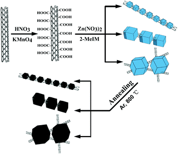
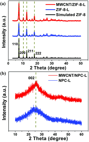
The schematic illustration of the synthetic process of MWCNT/NPCs is presented in Fig. 1. In the first step, the carboxylic groups (–COOH) were functionalized onto the MWCNTs through oxidation and acted as nucleation centers for subsequent ZIF-8 loading. After that, the MWCNTs modified with –COOH were well dispersed in methanol by ultrasonication, then Zn(NO3)2·6H2O and 2-MeIM with different concentrations were added into the above solution in sequence to grow small/middle/large sized ZIF-8. The obtained composites were denoted as MWCNT/ZIF-8-S/M/L. The obtained MWCNT/ZIF-8-S/M/L precursors were converted into MWCNT/NPC-S/M/L composites by carbonization. For more detail on the synthetic method for MWCNT/NPC composites, see the Experimental section.XRD measurements were conducted to analyze the crystal structure of the as-prepared hybrids. As shown in Fig. 2a, all diffraction peaks of the MWCNT/ZIF-8-L composite matched well with the simulated ZIF-8 crystals, and no peak for MWCNTs was observed, due to the relatively low intensity of MWCNTs, which is consistent with the previous report.48 In addition, the XRD pattern of the annealed products (Fig. 2b) (MWCNT/NPC-L and NPC-L) presented one broad peak located at around 26°, corresponding to the characteristic carbon (002) diffractions, indicating the existence of long-range, two-dimensional ordering in the carbon matrices, along with some graphitization.49–51 The XRD results for MWCNT/ZIF-8-M/S and the derived MWCNT/NPC-M/S composites are presented in Fig. S1,† indicating the similar crystalline structure of the samples. Significantly, no additional diffraction peaks from impurities were observed, indicating the complete conversion of the carbonaceous materials during annealing.
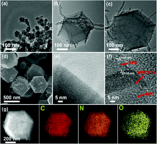
Morphologies and structures of the as-synthesized samples were determined by TEM and SEM characterizations. Fig. 3a–c show the TEM images of different sized MWCNT/ZIF-8 composites, and the ZIF-8 particles have good uniformity with average sizes of 50, 200, and 500 nm, respectively. The magnified SEM image (Fig. 3d) verified that the intertwined MWCNTs penetrate through the ZIF particles in the MWCNT/ZIF-8-L composites. As shown in Fig. 4a–c, after the high-temperature carbonization process, the annealed products (MWCNT/NPC-S/M/L) have preserved ZIF particle sizes and shapes of the original MWCNTs/ZIF-8-S/M/L precursors, which confirmed the role of ZIF-8 as an ideal template for NPCs (Fig. S2†). The typical HRTEM (Fig. 4f) image of an individual MWCNT/NPC-L shows a large amount of nanopores evenly distributed over the entire area, which confirmed the pore structure of NPCs. Moreover, the HRTEM image further demonstrated the formation of graphitic frameworks in the products and the complete removal of Zn. The elemental composition of the MWCNT/NPC-L hybrid was investigated by the energy dispersive spectroscopic (EDS) analysis (Fig. S3†), indicating the co-existence of C, N, and O in the hybrid, and the atomic ratio of C![[thin space (1/6-em)]](https://www.rsc.org/images/entities/char_2009.gif) :
:![[thin space (1/6-em)]](https://www.rsc.org/images/entities/char_2009.gif) N
N![[thin space (1/6-em)]](https://www.rsc.org/images/entities/char_2009.gif) :
:![[thin space (1/6-em)]](https://www.rsc.org/images/entities/char_2009.gif) O is 86.45
O is 86.45![[thin space (1/6-em)]](https://www.rsc.org/images/entities/char_2009.gif) :
:![[thin space (1/6-em)]](https://www.rsc.org/images/entities/char_2009.gif) 12.18
12.18![[thin space (1/6-em)]](https://www.rsc.org/images/entities/char_2009.gif) :
:![[thin space (1/6-em)]](https://www.rsc.org/images/entities/char_2009.gif) 1.35. The high-angle annular dark field scanning-TEM (HADDF-STEM) and related elemental mapping analysis of MWCNT/NPC-L hybrid are shown in Fig. 4g. The results confirmed the presence of C, N, and O elements and they were evenly distributed throughout the hybrid.
1.35. The high-angle annular dark field scanning-TEM (HADDF-STEM) and related elemental mapping analysis of MWCNT/NPC-L hybrid are shown in Fig. 4g. The results confirmed the presence of C, N, and O elements and they were evenly distributed throughout the hybrid.
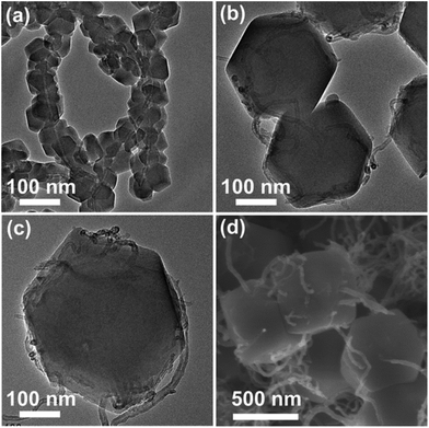 | ||
| Fig. 3 TEM images of MWCNT/ZIF-8 with various ZIF-8 crystal sizes: (a) MWCNT/ZIF-8-S, (b) MWCNT/ZIF-8-M, and (c) MWCNT/ZIF-8-L. (d) SEM image of MWCNT/ZIF-8-L. | ||
The porous structure of different MWCNT/NPC hybrids was further confirmed by N2 gas adsorption–desorption isotherms. As shown in Fig. 5a and S4,† all the MWCNT/NPC hybrids demonstrated a combination of type I and IV isotherms with hysteresis loops appearing in the P/P0 range of 0.5–1.0, which suggested the existence of mesopores. Moreover, the sharp uptakes of isotherms at low relative pressure (P/P0 < 0.1) indicated the typical microporous structures. NPC-L (Fig. 5c) and MWCNTs (Fig. 5e) show type I and type II isotherms, respectively, which are characteristic of microporous and macroporous structures, respectively. Therefore, our MWCNT/NPC hybrids have hierarchical porous structures with both micropores and mesopores, which is desired for supercapacitor applications.31,52 The specific surface area (SSA), pore volume and mean pore diameter are summarized in Table 1. The MWCNT/NPC-L hybrid showed the highest SSA of 928.2 m2 g−1 with a pore volume of 0.64 cm3 g−1 (density functional theory (DFT) method), compared with those of MWCNTs/NPC-M (884.6 m2 g−1, 0.57 cm3 g−1) and MWCNTs/NPC-S (642.5 m2 g−1, 0.53 cm3 g−1). The higher surface area of MWCNT/NPC-L is believed to be the reason for the better specific capacitance observed during electrochemical testing as shown later (see 3.2. Electrochemical characterization).
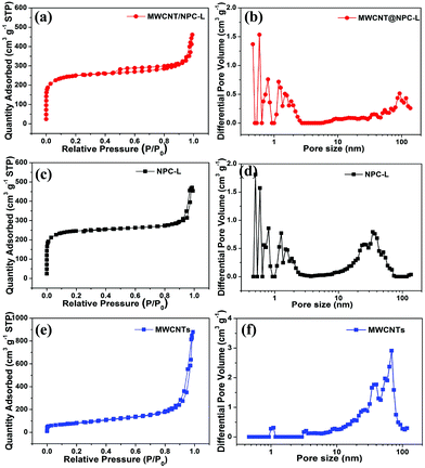 | ||
| Fig. 5 Nitrogen adsorption–desorption isotherms and pore size distribution: (a) and (b) MWCNT/NPC-L, (c) and (d) NPC-L, (e) and (f) MWCNTs. | ||
| Sample | S BET (m2 g−1) | S Langmuir (m2 g−1) | S micro (m2 g−1) | V total (cm3 g−1) | V micro (cm3 g−1) | Pore size (nm) |
|---|---|---|---|---|---|---|
| MWCNTs | 282 | 444.8 | 17.7 | 1.28 | 0.01 | 18.15 |
| NPC-L | 999.7 | 1124.7 | 660.8 | 0.79 | 0.27 | 3.17 |
| MWCNT/NPC-Mix | 898.6 | 1031.8 | 662.8 | 0.57 | 0.31 | 2.53 |
| MWCNT/NPC-S | 642.5 | 693.5 | 548.8 | 0.53 | 0.21 | 2.22 |
| MWCNT/NPC-M | 884.6 | 1040.7 | 748.9 | 0.57 | 0.29 | 2.57 |
| MWCNT/NPC-L | 928.2 | 1023.1 | 691.8 | 0.64 | 0.28 | 2.74 |
The presence of graphitic carbon after carbonization was confirmed by the Raman spectra (Fig. S5†). MWCNTs, NPC-L and MWCNT/NPC-L all demonstrated two distinct peaks at ∼1350 cm−1 (D band) and ∼1590 cm−1 (G band). The G band is associated with the tangential stretching mode of highly ordered pyrolytic graphite, while the D band is related to disorders and is caused by the in-plane imperfections such as defects. The ratio between the D band and G band (ID/IG) is used to evaluate the degree of graphitization.53 The ID/IG values of MWCNT/NPC-L, NPC-L and MWCNTs were 1.53, 1.72, and 1.1, respectively, indicating the higher graphitic level of MWCNT/NPC-L than that of NPC-L. The promoted graphitization degree of MWCNT/NPC-L (compared with NPC-L) comes from the introduction of MWCNTs and improves the electrical conductivity of the composite, which benefits the overall electrochemical activity.
XPS measurements were carried out to understand more details of MWCNT/NPC-L and NPC-L (Fig. 6). Both XPS spectra for MWCNT/NPC-L and NPC-L displayed a predominant graphitic C 1s peak at 285 eV, a N 1s peak at 400 eV and an O 1s peak at 540 eV (Fig. 6a). The content of C, N, and O in the obtained samples from XPS analysis are summarized in Table S2.† As shown in Fig. 6c and d, the high resolution N 1s spectrum can be fitted into three peaks, including pyridinic-N (N1, 398.7 ± 0.1 eV), pyrrolic-N (N2, 400 ± 0.1 eV), and graphitic-N (N3, 400.7 ± 0.2 eV).54 The deconvoluted C 1s signal in Fig. 6b shows a slightly asymmetric tail at higher binding energy, which is a common characteristic for nitrogen-doped carbon materials. The peak at 284.7 eV corresponds to a graphitic carbon phase (sp2 C–C), while the peak at 285.2 eV was assigned to sp3-hybridized carbon (sp3 C–C). The peak centered at 286.2 eV was ascribed to sp3 C–N.55 There was no peak for Zn 2p in the XPS spectra, indicating the complete removal of Zn residues by acid washing, consistent with the EDS mapping results.
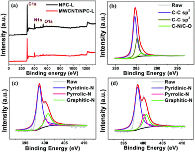 | ||
| Fig. 6 (a) XPS survey scan spectra. (b) C 1s spectra and (c) N 1s spectra of MWCNT/NPC-L. (d) N 1s spectra of NPC-L. | ||
3.2. Electrochemical characterization
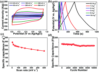
The cyclic voltammetry (CV) measurements were performed in a 1 M H2SO4 aqueous electrolyte using a three-electrode system (Fig. 7a). At a scan rate of 200 mV s−1, all CV curves showed relatively rectangular shapes within a potential range from 0 to 0.9 V (vs. Ag/AgCl), which were typical for EDLC. Notably, the humps were observed in the rectangular-like CV curves, indicating that the capacitive responses came from the combination of EDLC and Faradaic redox reactions. It has been previously reported that the nitrogen doping could introduce pseudocapacitance, enhance conductivity and promote wettability of the materials, thus improving the overall capacitance performance.50,55 The specific capacitance of MWCNT/NPC-L calculated from the CV curve based on eqn (1) was 293.4 F g−1 at 5 mV s−1, which was much higher than that of MWCNTs (85.8 F g−1) and NPC-L (166.7 F g−1), and also higher than that of MWCNT/NPC-M (222.6 F g−1), MWCNT/NPC-S (192.1 F g−1) and MWCNT/NPC-Mix (155.7 F g−1).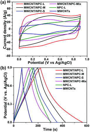 | ||
| Fig. 7 (a) CV curves at a potential scan rate of 200 mV s−1. (b) Charge–discharge curves at a current density of 1 A g−1 for MWCNT/NPC-S/M/L, MWCNT/NPC-Mix, NPC-L and MWCNTs. | ||
Galvanostatic charge–discharge (GCD) tests were performed in the range of 0–0.9 V at a current density of 1 A g−1 to evaluate the capacitance of the electrode materials (Fig. 7b). N doping can induce pseudocapacitance, which can cause all of the electrodes to display a quasi-linear appearance with a slight bend.50,56,57 Notably, at the beginning of the discharge process, no voltage drop was observed for MWCNT/NPC samples. MWCNT/NPC-L gives the largest specific capacitance of 302.2 F g−1 at a current density of 2 A g−1. The specific capacitance of these materials calculated from CV curves and GCD curves, respectively, are summarized in Table S3.†
Because the MWCNT/NPC-L sample exhibited relatively higher capacitance, the electrochemical behavior of MWCNT/NPC-L was thoroughly studied. As shown in Fig. 8a, with the scan rates increasing from 20 to 500 mV s−1, the MWCNT/NPC-L maintained the regular rectangular shapes without any redox peaks, suggesting the excellent transport properties of the electrode material. The CV curves of other tested materials, including MWCNT/NPC-S/M, NPC-L, MWCNT/NPC-Mix, and MWCNTs are all of lower capacitance when compared with MWCNT/NPC-L (see Fig. S6†). The GCD tests were also performed to compare MWCNT/NPC-L (Fig. 8b) and other materials (Fig. S7†). In GCD curves of MWCNT/NPC-L, symmetric triangular shapes and long discharging times at various current densities reveal its good columbic efficiency and superior capacitor behavior, consistent with the CV results.
The discharge time response increased with the decrease in current density, while the shapes of GCD curves were well maintained, suggesting the good rate properties of the MWCNT/NPC-L electrode. According to eqn (1), the specific capacitances based on CV curves are calculated and presented in Fig. 8c. The specific capacitance was 293.4 F g−1 at 5 mV s−1, which slightly decreased to 219.5 F g−1 at 200 mV s−1. To our knowledge, the values obtained in this work are among the largest values reported for NPC materials so far (Table S4†). It is worth noting that MWCNT/NPC-L showed excellent cycling stability (Fig. 8d); even after 10![[thin space (1/6-em)]](https://www.rsc.org/images/entities/char_2009.gif) 000 cycles at a scan rate of 100 mV s−1, the loss of capacitance was only 4.2%, demonstrating the advantage of MWCNT/NPC-L for supercapacitor applications.
000 cycles at a scan rate of 100 mV s−1, the loss of capacitance was only 4.2%, demonstrating the advantage of MWCNT/NPC-L for supercapacitor applications.
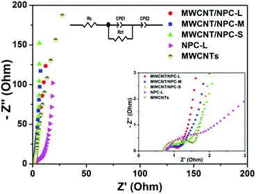
To further understand the superior performance of MWCNT/NPC-L, electrochemical impedance spectrometry (EIS) was used, which provided insights into the impedance distribution and ion diffusion. Fig. 9 displays the Nyquist plots of the MWCNT/NPCs samples and the corresponding equivalent circuit for the MWCNT/NPC-L electrode is modeled and presented in the inset. For each sample, the Nyquist plot showed a small semicircle at high frequency and a linear trait at low frequency, indicating purely capacitive behavior. The semicircle diameter represents the charge transfer resistance (Rct), which is related to the resistances at the interfaces of the active material/current collector and the electrode/electrolyte. The fitted Rct value of MWCNT/NPC-L is 0.41 Ohm, which was much lower than the value of MWCNTs (0.97 Ohm) and NPC-L (1.82 Ohm). The Rct value of MWCNT/NPC-L was lower than that of MWCNT/NPC-M (0.45 Ohm) and MWCNT/NPC-S (0.71 Ohm), indicating faster speeds of electron transfer and ion transport. The internal or equivalent series resistance (Rs), calculated from the intercept at the Z′-axis in the region of high frequency, was 0.77, 0.76, 0.74 Ohm for MWCNT/NPC-S/M/L electrodes, respectively. The lower Rs value of MWCNT/NPC-L further confirmed the better electrical conductivity. Furthermore, the straight line of the Nyquist plot represents the Warburg impedance (Rw). Clearly, all of the line slopes of MWCNT/NPC-S/M/L were very precipitous, revealing fast ion diffusion.58,59 Therefore, the EIS results further confirm that MWCNT/NPC-L is an excellent material for the supercapacitor electrode.
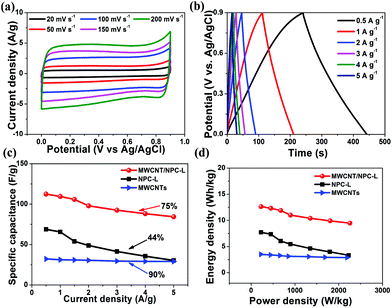
For practical application of MWCNT/NPC-L composites, we constructed a symmetric two-electrode supercapacitor cell (SSC) in 1 M H2SO4 aqueous electrolyte. We also fabricated NPC-L- and MWCNTs-based SSCs for comparison. Fig. 10a shows the CV curves of the SSC, which were carried out in a potential range of 0–0.9 V at various scan rates from 20 to 200 mV s−1. The quasi-rectangular shapes, without redox peaks, of all the CV curves indicate quick dynamics with high-power behaviors. The shapes of the CV curves were unaltered, even at high scan rates. The specific capacitance, energy and power density of the SSCs were calculated from the GCD curves at various applied current densities from 0.5 to 5 A g−1. As shown in Fig. 10b, there were no electrode-potential drops (IR drop), even at a relatively high current density of 5 A g−1, indicating the low internal ion-transport resistance of MWCNT/NPC-L composites (Fig. S8a†). Moreover, the typical linear discharge curves indicate the well-balanced charge storage of the symmetric device. The capacitance value was as high as 112.4 F g−1 at 0.5 A g−1, which was much larger than that of NPC-L-based SSC (68.8 F g−1, 0.5 A g−1) and MWCNTs-based SSC (32.2 F g−1, 0.5 A g−1). As for MWCNT/NPC-L-based SSC, even when the current density increased tenfold, up to 5 A g−1, the specific capacitance still remained at 84.3 F g−1. The capacitance retention was about 75%, indicating good rate capability (Fig. 10c), while the capacitance retention of the NPC-L-based SSC was only 44%; the long-term cycling stability performance of MWCNT/NPC-L-based SSC was tested by using GCD studies. After 2000 cycles at a current density of 5 A g−1, the capacitance retention was 90.2% (Fig. S8b†). Furthermore, the Ragone plot (specific power vs. specific energy) was used to evaluate the performance of the SSCs. As shown in Fig. 10d, at a current density of 0.5 A g−1, the energy density of MWCNT/NPC-L-based SSC reached 12.65 Wh kg−1 at a power density of 225.1 W kg−1, and remained at 9.5 Wh kg−1 at the power density of 2257.2 W kg−1 when the current density was up to 5 A g−1, which was much higher than the performance of the two other SSCs based on NPC-L (7.73 Wh kg−1, 224.8 W kg−1, 0.5 A g−1) and MWCNTs (3.51 Wh kg−1, 221.7 W kg−1, 0.5 A g−1). These results indicate that the MWCNT/NPC-L composite is a very promising supercapacitor electrode material, especially for high-rate applications.
We also noticed that for NPC materials, the high SSA is not necessarily the single dominating factor for good performance. Table S5† compares high performance supercapacitor materials with various SSAs. It can be seen that the material capacitance is not linearly improved when very high SSAs are achieved. There is evidence showing that low SSA materials could give a high capacitance. For our MWCNT/NPC-L and NPC-L comparison, the difference in SSAs was within 10%, while the capacitance for the former was almost double that of the latter. This is believed to be due to the introduction of MWCNTs, which greatly promote the conductivity of the carbon matrix as well as the generation of hierarchical pore structures. Such advanced nanostructure control greatly improves material performance and opens new avenues towards advanced function materials.
4. Conclusion
In summary, MWCNT/ZIF-8 composites with controlled ZIF-8 sizes have been prepared by in situ growth of ZIF-8 on MWCNTs. After carbonization, the MWCNT/NPC hybrids, featured with high specific surface area, high graphitization degree, and hierarchical pore structure, were successfully synthesized, retaining their original morphologies. The optimum electrode (MWCNT/NPC-L) displayed high electrochemical capacitance and good stability, which shows tremendous potential for energy-storage applications.Acknowledgements
This work was supported financially by Chinese ministry of science and technology (no. 2016 YFA0200700), National Key Basic Research Program of China (2014CB931801, Z. Y. T.), National Natural Science Foundation of China (21676093, Y. H. Z.; 21471056, Y. H. Z.; 21473044, C. G. L.; 21475029 and 91427302, Z. Y. T.), Instrument Developing Project of the Chinese Academy of Sciences (YZ201311, Z. Y. T.), CAS-CSIRO Cooperative Research Program (GJHZ1503, Z. Y. T.), and “Strategic Priority Research Program” of Chinese Academy of Sciences (XDA09040100, Z. Y. T.).Notes and references
- Z. Yu, L. Tetard, L. Zhai and J. Thomas, Energy Environ. Sci., 2015, 8, 702–730 CAS.
- E. Lim, C. Jo and J. Lee, Nanoscale, 2016, 8, 7827–7833 RSC.
- B. Mendoza-Sánchez and Y. Gogotsi, Adv. Mater., 2016, 28, 6104–6135 CrossRef PubMed.
- M. Salanne, B. Rotenberg, K. Naoi, K. Kaneko, P. L. Taberna, C. P. Grey, B. Dunn and P. Simon, Nat. Energy, 2016, 1, 16070 CrossRef CAS.
- G. Yu, X. Xie, L. Pan, Z. Bao and Y. Cui, Nano Energy, 2013, 2, 213–234 CrossRef CAS.
- G. Chen, Y. Su, P. Kuang, Z. Liu, D. Chen, X. Wu, N. Li and S. Qiao, Chem. – Eur. J., 2015, 21, 4614–4621 CrossRef CAS PubMed.
- Y. Su, K. Xiao, N. Li, Z. Liu and S. Qiao, J. Mater. Chem. A, 2014, 2, 13845–13853 CAS.
- B. Ding, J. Wang, Y. Wang, Z. Chang, G. Pang, H. Dou and X. Zhang, Nanoscale, 2016, 8, 11136–11142 RSC.
- S. Zhu, J. Li, L. Ma, L. Guo, Q. Li, C. He, E. Liu, F. He, C. Shi and N. Zhao, ACS Appl. Mater. Interfaces, 2016, 8, 11720–11728 CAS.
- J. Yu, W. Lu, S. Pei, K. Gong, L. Wang, L. Meng, Y. Huang, J. P. Smith, K. S. Booksh, Q. Li, J. Byun, Y. Oh, Y. Yan and T. Chou, ACS Nano, 2016, 10, 5204–5211 CrossRef CAS PubMed.
- L. Wen, F. Li and H. Cheng, Adv. Mater., 2016, 28, 4306–4337 CrossRef CAS PubMed.
- Y. Song, H. Hu, M. Feng and H. Zhan, ACS Appl. Mater. Interfaces, 2015, 7, 25793–25803 CAS.
- E. Iwama, N. Kawabata, N. Nishio, K. Kisu, J. Miyamoto, W. Naoi, P. Rozier, P. Simon and K. Naoi, ACS Nano, 2016, 10, 5398–5404 CrossRef CAS PubMed.
- G. Sun, X. Zhang, R. Lin, B. Chen, L. Zheng, X. Huang, L. Huang, W. Huang, H. Zhang and P. Chen, Adv. Electron. Mater., 2016, 2, 1600102 CrossRef.
- Y. Wang, B. Chen, Y. Zhang, L. Fu, Y. Zhu, L. Zhang and Y. Wu, Electrochim. Acta, 2016, 213, 260–269 CrossRef CAS.
- Y. Zhang, B. Lin, J. Wang, J. Tian, Y. Sun, X. Zhang and H. Yang, J. Mater. Chem. A, 2016, 4, 10282–10293 CAS.
- F. Lai, Y.-E. Miao, L. Zuo, H. Lu, Y. Huang and T. Liu, Small, 2016, 12, 3235–3244 CrossRef CAS PubMed.
- Y. Zhu, S. Murali, M. D. Stoller, K. J. Ganesh, W. Cai, P. J. Ferreira, A. Pirkle, R. M. Wallace, K. A. Cychosz, M. Thommes, D. Su, E. A. Stach and R. S. Ruoff, Science, 2011, 332, 1537–1541 CrossRef CAS PubMed.
- S. Chen, J. Duan, Y. Tang and S. Qiao, Chem. – Eur. J., 2013, 19, 7118–7124 CrossRef CAS PubMed.
- X. Huang, X. Qi, F. Boey and H. Zhang, Chem. Soc. Rev., 2012, 41, 666–686 RSC.
- P. Chen, J.-J. Yang, S.-S. Li, Z. Wang, T.-Y. Xiao, Y.-H. Qian and S.-H. Yu, Nano Energy, 2013, 2, 249–256 CrossRef CAS.
- X. Li, W. Xing, J. Zhou, G. Wang, S. Zhuo, Z. Yan, Q. Xue and S. Qiao, Chem. – Eur. J., 2014, 20, 13314–13320 CrossRef CAS PubMed.
- B. Kruner, J. Lee, N. Jackel, A. Tolosa and V. Presser, ACS Appl. Mater. Interfaces, 2016, 8, 9104–9115 Search PubMed.
- P. Pachfule, D. Shinde, M. Mainak and Q. Xu, Nat. Chem., 2016, 8, 718–724 CrossRef CAS PubMed.
- W. Meng, W. Chen, L. Zhao, Y. Huang, M. Zhu, Y. Huang, Y. Fu, F. Geng, J. Yu, X. Chen and C. Zhi, Nano Energy, 2014, 8, 133–140 CrossRef CAS.
- B. Liu, H. Shioyama, T. Akita and Q. Xu, J. Am. Chem. Soc., 2008, 130, 5390–5391 CrossRef CAS PubMed.
- M. Hu, J. Reboul, S. Furukawa, N. Torad, Q. Ji, P. Srinivasu, K. Ariga, S. Kitagawa and Y. Yamauchi, J. Am. Chem. Soc., 2012, 134, 2864–2867 CrossRef CAS PubMed.
- W. Chaikittisilp, M. Hu, H. Wang, H. Huang, T. Fujita, K. C. W. Wu, L. Chen, Y. Yamauchi and K. Ariga, Chem. Commun., 2012, 48, 7259–7261 RSC.
- N. L. Torad, M. Hu, Y. Kamachi, K. Takai, M. Imura, M. Naito and Y. Yamauchi, Chem. Commun., 2013, 49, 2521–2523 RSC.
- R. R. Salunkhe, C. Young, J. Tang, T. Takei, Y. Ide, N. Kobayashi and Y. Yamauchi, Chem. Commun., 2016, 52, 4764–4767 RSC.
- A. J. Amali, J. K. Sun and Q. Xu, Chem. Commun., 2014, 50, 1519–1522 RSC.
- L. Yang, B. Tang and P. Wu, J. Mater. Chem. A, 2015, 3, 15838–15842 CAS.
- C. Li, C. Hu, Y. Zhao, L. Song, J. Zhang, R. Huang and L. Qu, Carbon, 2014, 78, 231–242 CrossRef CAS.
- R. R. Salunkhe, Y. Kamachi, N. L. Torad, S. M. Hwang, Z. Sun, S. X. Dou, J. H. Kim and Y. Yamauchi, J. Mater. Chem. A, 2014, 2, 19848–19854 CAS.
- Y. Z. Zhang, Y. Wang, Y. L. Xie, T. Cheng, W. Y. Lai, H. Pang and W. Huang, Nanoscale, 2014, 6, 14354–14359 RSC.
- N. L. Torad, R. R. Salunkhe, Y. Li, H. Hamoudi, M. Imura, Y. Sakka, C. C. Hu and Y. Yamauchi, Chem. – Eur. J., 2014, 20, 7895–7900 CrossRef CAS PubMed.
- H. Hu, B. Guan, B. Xia and X. W. Lou, J. Am. Chem. Soc., 2015, 137, 5590–5595 CrossRef CAS PubMed.
- R. R. Salunkhe, J. Tang, Y. Kamachi, T. Nakato, J. H. Kim and Y. Yamauchi, ACS Nano, 2015, 9, 6288–6296 CrossRef CAS PubMed.
- J. Tang and Y. Yamauchi, Nat. Chem., 2016, 8, 638–639 CrossRef CAS PubMed.
- L. Zhang, Z. Su, F. Jiang, L. Yang, J. Qian, Y. Zhou, W. Li and M. Hong, Nanoscale, 2014, 6, 6590–6602 RSC.
- G. Xu, B. Ding, J. Pan, J. Han, P. Nie, Y. Zhu, Q. Sheng and H. Dou, J. Mater. Chem. A, 2015, 3, 23268–23273 CAS.
- M. Jiang, X. Cao, D. Zhu, Y. Duan and J. Zhang, Electrochim. Acta, 2016, 196, 699–707 CrossRef CAS.
- V. S. Veerasamy, J. Yuan, G. A. J. Amaratunga, W. I. Milne, K. W. R. Gilkes, M. Weiler and L. M. Brown, Phys. Rev. B: Condens. Matter, 1993, 48, 17954–17959 CrossRef CAS.
- T. Lin, I.-W. Chen, F. Liu, C. Yang, H. Bi, F. Xu and F. Huang, Science, 2015, 350, 1508–1513 CrossRef CAS PubMed.
- D. Hulicova, J. Yamashita, Y. Soneda, H. Hatori and M. Kodama, Chem. Mater., 2005, 17, 1241–1247 CrossRef CAS.
- H. Yi, H. Wang, Y. Jing, T. Peng and X. Wang, J. Power Sources, 2015, 285, 281–290 CrossRef CAS.
- S. Guo, S. Dong and E. Wang, Adv. Mater., 2010, 22, 1269–1272 CrossRef CAS PubMed.
- A. Cao, C. Xu, J. Liang, D. Wu and B. Wei, Chem. Phys. Lett., 2001, 344, 13–17 CrossRef CAS.
- Y. Zaoxue, C. Mei and S. P. Kang, J. Mater. Chem., 2012, 22, 2133–2139 RSC.
- J. Tang, R. R. Salunkhe, J. Liu, N. L. Torad, M. Imura, S. Furukawa and Y. Yamauchi, J. Am. Chem. Soc., 2015, 137, 1572–1580 CrossRef CAS PubMed.
- G. Gupta, D. A. Slanac, P. Kumar, J. D. Wiggins-Camacho, J. Kim, R. Ryoo, K. J. Stevenson and K. P. Johnston, J. Phys. Chem. C, 2010, 114, 10796–10805 CAS.
- T. Yang, R. Zhou, D. Wang, S. Jiang, Y. Yamauchi, S. Qiao, M. J. Monteiro and J. Liu, Chem. Commun., 2015, 51, 2518–2521 RSC.
- A. Sadezky, H. Muckenhuber, H. Grothe, R. Niessner and U. Pöschl, Carbon, 2005, 43, 1731–1742 CrossRef CAS.
- S. Krzysztof, D. Roman, P. Zofia and W. Stefan, Carbon, 1995, 33, 1383–1392 CrossRef.
- S. Maldonado, S. Morin and K. J. Stevenson, Carbon, 2006, 44, 1429–1437 CrossRef CAS.
- L. Zhao, L. Fan, M. Zhou, H. Guan, S. Qiao, M. Antonietti and M. M. Titirici, Adv. Mater., 2010, 22, 5202–5202 CrossRef CAS PubMed.
- E. Iyyamperumal, S. Wang and L. Dai, ACS Nano, 2012, 6, 5259–5265 CrossRef CAS PubMed.
- S. Hyun-Kon, H. Hee-Young, L. Kun-Hong and D. L. H, Electrochim. Acta, 2000, 45, 2241–2257 CrossRef.
- Y. Zhang, B. Lin, Y. Sun, P. Han, J. Wang, X. Ding, X. Zhang and H. Yang, Electrochim. Acta, 2016, 188, 490–498 CrossRef CAS.
Footnote |
| † Electronic supplementary information (ESI) available: Additional figures and tables as noted in the text. See DOI: 10.1039/c6nr08987a |
| This journal is © The Royal Society of Chemistry 2017 |

