 Open Access Article
Creative Commons Attribution 3.0 Unported Licence
Sequential curing of off-stoichiometric thiol–epoxy thermosets with a custom-tailored structure†
Xavier
Fernández-Francos
*a,
Ali-Osman
Konuray
a,
Alberto
Belmonte
b,
Silvia
De la Flor
b,
Àngels
Serra
c and
Xavier
Ramis
 a
a
aThermodynamics Laboratory, ETSEIB, Universitat Politècnica de Catalunya, Av. Diagonal 647, 08028 Barcelona, Spain. E-mail: xavier.fernandez@mmt.upc.edu; Fax: +34 934017389; Tel: +34 934016594
bDepartment of Mechanical Engineering, Universitat Rovira i Virgili, Campus Sescelades, Av. dels Països Catalans, 26, 43007, Tarragona, Spain
cDepartment of Analytical and Organic Chemistry, Universitat Rovira i Virgili, Campus Sescelades, c/Marcel·lí Domingo s/n, 43007, Tarragona, Spain
First published on 26th February 2016
Abstract
A new dual-curing system based on sequential thiol–epoxy click polycondensation and epoxy anionic homopolymerization was studied. Formulations of diglycidyl ether of bisphenol A and trimethylolpropane tris(3-mercaptopropionate) with 1-methylimidazole as a base catalyst and excess of epoxy groups were prepared and characterized. The curing process is sequential: fast thiol–epoxy polycondensation takes place first, followed by slower homopolymerization of excess epoxy groups. This makes it possible to define curing sequences with easy time–temperature control for both curing stages. The network build-up process during the first curing stage can be easily modelled assuming ideal polycondensation, which allows tailoring the structure and properties of the intermediate materials. The homopolymerization of the excess epoxy groups in the second curing stage results in a higher glass transition temperature (Tg) in comparison with the stoichiometric thiol–epoxy material, thus extending the application of thiol–epoxy thermosets to wider temperature ranges.
1 Introduction
Dual curing is a processing methodology based on the combination of two different and compatible polymerization reactions taking place simultaneously or sequentially, in a well-controlled way. Sequential dual-curing processing makes it possible to obtain stable materials after the first curing stage that maintain the ability, upon application of a second stimulus, to activate the second curing stage and complete the processing leading to a fully-cured material with the desired final properties,1 an advantage that can be exploited in flexible processing scenarios.Click reactions2–5 are highly interesting from the synthesis point of view because of their simplicity, efficiency, selectivity and environmentally-friendly conditions. This makes them advisable for incorporation into dual curing procedures in a convenient way so as to reach technological applicability. Among them, thiol-click reactions4 are suitable candidates since thiols are able to react under mild conditions by forming radical or anionic species, making it possible to prepare thermosets in a controlled manner by selecting the appropriate conditions and catalysts. Indeed, a number of dual-curing systems are based on thiol-click reactions: click radical thiol–ene combined with base-catalyzed thiol–epoxy reactions,6–9 base-catalyzed thio-Michael addition to acrylates with radical polymerization of excess acrylates,1 or thio-Michael addition combined with thiol–ene reactions.10 Other examples making use of base-catalyzed click reactions are possible, such as the combination of base-catalyzed thiol–epoxy, thio-Michael addition, and radical-initiated thiol–acrylate reactions,11 or aza-Michael addition to acrylates followed by radical photopolymerization of excess acrylates.12 Radical thiol–ene reactions have also been combined with methacrylates13 and vinyl esters.14 UV-activated thiol–ene/epoxy homopolymerization processes15–18 lead to the in situ formation of a thermally latent species that resumes and completes the curing process upon heating in the second stage.
Base-catalyzed click thiol–epoxy formulations have different applications such as high performance coatings, adhesives and composites.4 Thiol–epoxy thermosets are also interesting for optical applications because of their high transparency19 and their potential use as shape-memory materials.20 Recent developments have been made in the area of dual-curing systems,6–8 novel catalytic systems for latent thermally curable formulations19 and the use of photolatent bases.21,22 A major drawback of thiol–epoxy thermosets is their low glass transition temperature6,19 even in dual-curable systems. This can be overcome by means of using higher functional epoxy monomers or thiol crosslinkers,20,23 but the effect is discrete. It is known that the use of an epoxy excess in epoxy–amine formulations leads to further crosslinking due to epoxy homopolymerization24–26 producing a significant enhancement in the thermal–mechanical properties,27 and the same can be observed in epoxy–anhydride formulations with excess epoxy groups.28 A controlled excess of epoxy in phenol–epoxy formulations29 resulted in a general enhancement in the mechanical properties but a complex effect on the glass transition temperature due to a balance between crosslinking and monomer flexibility. Taking into account the starting low glass transition temperature of stoichiometric thiol–epoxy systems, it is expected that the use of epoxy excess in thiol–epoxy formulations could produce a significant enhancement of the thermal and mechanical properties. However, off-stoichiometric epoxy formulations may not lead to dual-curable systems with a controlled curing sequence. The combination of epoxy–amine and epoxy homopolymerization leads to a curing profile without a clear separation between both reactions.27 The same is observed in epoxy–anhydride,28 epoxy–bislactone,30 phenol–epoxy31 or epoxy–carboxylic acid32 formulations with excess epoxy groups. A common problem in some of these cases is the moderate or low reaction rate of the first curing reaction due to the stability of the propagating species,30,31 making it difficult to apply such systems to a dual-curing processing scheme. In contrast, thiol–epoxy curing with tertiary amines is very fast and can take place at a convenient rate even at room temperature, depending on the concentration33 and the type of catalyst employed,19 while anionic epoxy homopolymerization usually takes place at higher temperatures.34,35 In addition, the thiol–epoxy reaction is the only chemical process taking place in the presence of thiol groups.33 Off-stoichiometric thiol–epoxy formulations are therefore potential candidates for sequential dual-curable systems with a clear separation between processes.
In this work, the curing of thiol–epoxy formulations with excess of epoxy groups is studied, with a two-fold purpose: (1) exploiting a new concept of dual-curing based on the combination of two thermal curing processes with different reaction temperatures for flexible processing and tailoring of materials in the intermediate and final stages, and (2) enhancing the thermomechanical properties of click thiol–epoxy thermosets. Mixtures of diglycidyl ether of bisphenol A and trimethylolpropane tris(3-mercaptopropionate) are prepared with different thiol![[thin space (1/6-em)]](https://www.rsc.org/images/entities/char_2009.gif) :
:![[thin space (1/6-em)]](https://www.rsc.org/images/entities/char_2009.gif) epoxy equivalent ratios and cured with 1-methylimidazole as the catalyst for the thiol–epoxy reaction19 and an anionic initiator for the epoxy homopolymerization.34,35 The curing process is monitored using DSC. The thermomechanical properties are determined with DSC and DMA. The curing kinetics is studied using model-free isoconversional methods, and the network structure is analyzed using statistical methods.
epoxy equivalent ratios and cured with 1-methylimidazole as the catalyst for the thiol–epoxy reaction19 and an anionic initiator for the epoxy homopolymerization.34,35 The curing process is monitored using DSC. The thermomechanical properties are determined with DSC and DMA. The curing kinetics is studied using model-free isoconversional methods, and the network structure is analyzed using statistical methods.
2 Experimental
2.1 Materials
Diglycidyl ether of bisphenol A (DGEBA) with an epoxy equivalent weight of 172–176 g eq.−1 (Aldrich), has been dried at 80 °C under vacuum for 2 hours and stored in a dessicator prior to use. The resin has been coded as DG174, the numbers indicating the assumed epoxy equivalent weight. Trimethylolpropane tris(3-mercaptopropionate) (S3) and 1-methylimidazole (1MI) from Sigma Aldrich were used as received. Mixtures with different ratios r of thiol groups with respect to epoxy groups were prepared. 1 phr (parts per hundred of the total mixture) of 1MI with respect to the total mixture was added as a catalyst. The samples were quickly stirred with a spatula and analyzed immediately after or stored at −18 °C before use. Table 1 shows the composition of the different formulations. The formulations have been coded as DG174S3-r where r is the thiol![[thin space (1/6-em)]](https://www.rsc.org/images/entities/char_2009.gif) :
:![[thin space (1/6-em)]](https://www.rsc.org/images/entities/char_2009.gif) epoxy equivalent ratio.
epoxy equivalent ratio.
| Formulation | r | wt% DGEBA | wt% thiol |
|---|---|---|---|
| DG174S3-1 | 1 | 56.74 | 43.26 |
| DG174S3-0.75 | 0.75 | 63.62 | 36.38 |
| DG174S3-0.5 | 0.5 | 72.40 | 27.60 |
| DG174S3-0.25 | 0.25 | 83.99 | 16.01 |
Completely cured samples of the formulations were prepared by casting the samples in an aluminum mould and keeping them in an oven for 1 h at 80 °C and 2 h at 120 °C to ensure complete curing.
2.2 Characterization techniques
A differential scanning calorimeter Mettler DSC822e calibrated with indium standards was used to study the dynamic curing of the different formulations. Samples of ca. 5–10 mg were placed inside an aluminum pan with a pierced lid and were cured at different heating rates, from 0 to 250 °C, under a nitrogen atmosphere. For the isothermal curing of the different formulations, a differential scanning calorimeter Mettler DSC821e calibrated with indium standards was used. Samples of ca. 5–10 mg were placed inside an aluminum pan with a pierced lid and were cured at different temperatures, until the process was complete and a flat horizontal baseline was achieved. The calorimetric degree of conversion was determined as xDSC = Δh/Δhtotal, where Δh is the reaction heat released up to a temperature T or time t and Δhtotal is the total reaction heat evolved in a dynamic run. The calorimetric rate was determined as dxDSC/dt = dh/dt/Δhtotal, where dh/dt is the heat flow. The glass transition temperature (Tg) of the samples in the intermediate state and those completely cured following the schedule defined in the Materials section was determined by DSC from a scan at 10 °C min−1, and taken as the half-way point in the jump in the heat capacity step, following the DIN 51007 method in the STARe software by Mettler. The heat capacity step during the glass transition (ΔCp) was also determined.The curing kinetics were analyzed by isoconversional model-free kinetic methods36 and the kinetics information was used to simulate different processing scenarios. The calorimetric conversion was transformed into epoxy group conversion xepoxy for the kinetics analysis. The details for the specific procedures can be found in the ESI.†
A FTIR spectrometer Bruker Vertex 70 with an attenuated total reflection accessory with thermal control and a diamond crystal (Golden Gate Heated Single Reflection Diamond ATR, Specac-Teknokroma) and equipped with a mid-band liquid nitrogen-cooled mercury–cadmium–telluride (MCT) detector was used to monitor the curing process. Spectra were collected at the curing temperature in the absorbance mode at a resolution of 4 cm−1 in the wavelength range of 600 to 4000 cm−1 and 20 scans were averaged for each spectrum. The spectra were corrected for the wavelength dependence of the absorbance in ATR devices. The peak at 1605 cm−1 (ring stretch of p-disubstituted benzene ring of DGEBA) was used as an internal standard. The disappearance of the absorbance peaks at 915 cm−1 (epoxy bending) was used only for the qualitative analysis of the curing process due to overlapping with a peak being formed within the same frequency range. The normalized absorbance of the broad band corresponding to the hydroxyl group formed by the thiol–epoxy reaction at 3500 cm−1, was also used for comparison purposes. The band corresponding to the S–H stretch vibration of the thiol group at 2570 cm−1 was only analyzed from a qualitative point of view.
A TA Instruments DMA Q800 was used to study the dynamic-mechanical properties of the materials. Prismatic rectangular samples (ca. 10 × 12 × 1.3 mm3) were analyzed in single-cantilever mode at 1 Hz and 10 μm strain amplitude and at a heating rate of 3 °C min−1 from 25 to 180 °C.
3 Theoretical
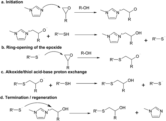
The curing mechanism of thiol–epoxy reactions catalyzed by tertiary amines is complex and involves a number of reaction steps. One of the accepted reaction mechanisms is based on the acid–base equilibrium reaction between the tertiary amine and the thiol, producing a thiolate anion that propagates the reaction by nucleophilic attack on the epoxy ring and regeneration of the thiolate/base by proton exchange between the formed alkoxide and another thiol or the protonated base.4,6,19,37 This mechanism has been recently shown to describe the curing of thiol–epoxy systems catalyzed by strong bases such as DBU,37 showing autocatalysis also caused by the hydroxyl groups formed in the course of the reaction.However, the low basicity of some tertiary amines that can be used for the thiol–epoxy reaction19 such as 1MI, with a pKa of the conjugate acid of ca. 7,38 and the poor acid character of the thiol, with a pKa of about 9,39 makes the proton exchange leading to the formation of a thiolate anion highly unlikely. An alternative reaction mechanism was recently used to model successfully the thiol–epoxy curing catalyzed by a moderately basic tertiary amine such as BDMA.33Scheme 1 shows the proposed mechanism using 1MI as the catalyst. First of all, there is a nucleophilic attack of the tertiary amine on the epoxy ring, with the assistance of a proton donor such as an alcohol to facilitate ring-opening (Scheme 1a), followed by proton exchange between the thiol and the alkoxide to produce the thiolate anion and a hydroxyl ammonium compound. The thiolate anion propagates the reaction by nucleophilic attack on the epoxy ring (Scheme 1b) and the regeneration of the thiolate anion by proton exchange of the formed alkoxide with another thiol, leading to the thio–ether condensation product with a hydroxyl group (Scheme 1c). The nucleophilic displacement of the amine by the thiolate anion (Scheme 1d) leads to the condensation product and regeneration of the initiator. Hydroxyl groups are more effective proton donors than thiol groups in terms of catalytic effect,40 therefore the hydroxyl groups produced in the thiol–epoxy reaction should favour the nucleophilic attack of the tertiary amine on the epoxy ring35,41,42 as well as the nucleophilic attack of the thiolate anion.37
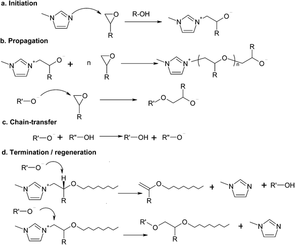
Imidazoles are also known to act as initiators for the anionic homopolymerization of epoxides.34,35,42–44 In the absence of thiol groups, the reaction mechanism, shown in Scheme 2, involves the initiation by nucleophilic attack of the imidazole on the epoxy ring (Scheme 2a), propagation by the different alkoxide anions present in the system (Scheme 2b), alkoxide–hydroxyl proton exchange (Scheme 2c) and two different termination or regeneration mechanisms (Scheme 2d), one by hydrogen abstraction (β-elimination) and another one by nucleophilic displacement of the imidazole,35,45 each one with a clearly different effect in terms of network build-up.42 Given that in stoichiometric thiol–epoxy formulations the thiol–epoxy condensation governs the curing process,33 anionic epoxy homopolymerization can only take place in an excess of epoxy groups, once the thiol groups are exhausted, as seen for other systems.30 Hydroxyl groups produced by the thiol–epoxy reaction should have a catalytic effect on the anionic homopolymerization of epoxides catalyzed by tertiary amines35,41,42 and this would contribute to reduce the amount of initiator required to complete the epoxy homopolymerization in comparison with neat epoxy homopolymerization systems.27,43,46
4 Results and discussion
4.1 Kinetics analysis of the curing process
The dynamic curing processes at 10 °C min−1 of formulations DG174S3-r, with different thiol![[thin space (1/6-em)]](https://www.rsc.org/images/entities/char_2009.gif) :
:![[thin space (1/6-em)]](https://www.rsc.org/images/entities/char_2009.gif) epoxy equivalent ratios, were studied. In the thermograms given in the upper graph of Fig. 1 it can be observed that, except for the formulation DG174S3-1, the curing process consists of two well-separated processes, the first one a sharp exotherm occurring at low temperatures, and the second one taking place at higher temperatures at a much slower rate. Sharp curing profiles like these are an indication of risk of temperature overshoot during the processing of thick parts, but also suggest that curing can take place in a more controlled way at a low temperature. Similar curing profiles had also been observed in stoichiometric thiol–epoxy formulations using different tertiary amine catalysts.19 The separation of the two processes and the difference in the reaction rate between them is clearly observed in the calorimetric conversion curves represented in the lower graph of Fig. 1.
epoxy equivalent ratios, were studied. In the thermograms given in the upper graph of Fig. 1 it can be observed that, except for the formulation DG174S3-1, the curing process consists of two well-separated processes, the first one a sharp exotherm occurring at low temperatures, and the second one taking place at higher temperatures at a much slower rate. Sharp curing profiles like these are an indication of risk of temperature overshoot during the processing of thick parts, but also suggest that curing can take place in a more controlled way at a low temperature. Similar curing profiles had also been observed in stoichiometric thiol–epoxy formulations using different tertiary amine catalysts.19 The separation of the two processes and the difference in the reaction rate between them is clearly observed in the calorimetric conversion curves represented in the lower graph of Fig. 1.
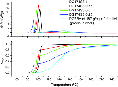 | ||
| Fig. 1 Heat flow and calorimetric conversion during curing of DG174S3-X formulations at 10 °C min−1 plotted with respect to the reference temperature of the DSC. The results from a previous analysis of the curing of DGEBA with 1MI are also shown.27 | ||
In Fig. 1 it can be seen that the magnitude of the first process decreases with decreasing stoichiometric ratio while the magnitude of the second one increases. In addition, the temperatures of the first curing process are within the temperature range of the stoichiometric DG174S3-1 formulation, while the temperature range of the second curing process corresponds to that of the anionic homopolymerization of DGEBA catalyzed with 1MI.27Table 2 shows a comparison of the experimental reaction heat Δhexp measured at 10 °C min−1 and a theoretical reaction heat Δhtheor calculated assuming 130 kJ mol−1 for the thiol–epoxy reaction19,23,33 and 100 kJ mol−1 for the epoxy homopolymerization.30,34,35 Within the experimental error, the experimental and calculated values are very similar, indicating full conversion of epoxy groups at the end of the curing process. Moreover, the theoretical contribution of the thiol–epoxy reaction to the overall reaction heat is in excellent agreement with the measured contribution of the first step. Taking into account all this evidence and the recent work by Loureiro et al.,33 it can be deduced that the first curing process corresponds to the thiol–epoxy curing catalyzed by 1MI, while the second one corresponds to the homopolymerization of the excess epoxy groups, taking place once the thiol groups are exhausted.
| Formulation | Δhexp. (J g−1) | Δhtheor. (J g−1) | Thiol–epoxy contribution | Measured 1st step contribution |
|---|---|---|---|---|
| DG174S3-1 | 432 | 419.7 | 1 | ∼1 |
| DG174S3-0.75 | 454.4 | 443.5 | 0.80 | ∼0.8 |
| DG174S3-0.5 | 462.6 | 473.8 | 0.57 | ∼0.6 |
| DG174S3-0.25 | 508.8 | 513.8 | 0.30 | ∼0.3 |
The shape of the curing curves shown in Fig. 1 indicates autocatalysis caused by the formation of hydroxyl groups that activate the epoxy ring and facilitate the nucleophilic attack of the initiator and the thiolate.33,37 The fact that the reaction is sharply activated only after reaching certain temperature in the dynamic experiments suggests that there is an induction period due to the slow generation of the initial active species.33 Isothermal curing experiments (see Fig. 1 in the ESI†) confirmed the autocatalytic behaviour and the existence of an induction period that was shortened when DGEBA with a higher hydroxyl group content was used.
The difference in the reaction rate between both processes indicates that it may be possible to easily separate the two curing stages. This clear difference can be explained by the different reaction mechanisms and may be rationalized, in particular, by the activity of the formed zwitter-ion after initiation by the nucleophilic attack of the imidazole on the epoxy ring (Schemes 1a and 2a) and the presence of thiol groups. In the presence of thiol groups, there is a fast acid–base proton exchange between the initial zwitter-ion or the other alkoxide species present in the system and the thiol leading to the formation of thiolate anions (Schemes 1a and c), due to the difference in the pKa of the thiol/thiolate and the hydroxyl/alkoxide acid–base equilibrium pairs. The thiolate anion can subsequently propagate the reaction by nucleophilic attack on the epoxy ring (Scheme 1b), or else regenerate the initiator by nucleophilic displacement of the initiator (Scheme 1d). In the absence of thiol such acid–base reactions cannot take place and the reaction mechanism changes from the thiol–epoxy polycondensation (Scheme 1) to epoxy polyetherification (Scheme 2). Heise and Martin studied the reaction of epoxides with various imidazoles43,44 and concluded that the formation of different epoxy–imidazole adducts took place to completion and that they needed to be “activated” before etherification could start.44 The appearance of an induction period with an epoxy conversion proportional to the initiator content, before the etherification started, was also observed by other researchers.34,35 Taking all this into account and following Scheme 2, it is hypothesized that the initial zwitter-ion adduct has a lower reactivity than the other alkoxide anions present in the system due to the proximity of the positive and negative charges. Therefore, the first of the propagation steps in Scheme 2b would take place at a very low rate and delay the start of the epoxy polyetherification. Once a different alkoxide anion was formed, the propagation rate would increase. In addition, regeneration reactions (Scheme 2d) are highly frequent in the epoxy polyetherification catalyzed by tertiary amines,34,35,42,45 hence reducing the overall amount of propagating species and decreasing dramatically the reaction rate with respect to that of the thiol–epoxy reaction. The large difference in the reaction rates of the thiol–epoxy and homopolymerization reaction also suggests that the nucleophilic displacement reaction in Scheme 1d is also less frequent, leading to a higher concentration of active species throughout the first reaction.
Fig. 1 (see also the ESI†) also shows that the curing process starts earlier with a decreasing thiol![[thin space (1/6-em)]](https://www.rsc.org/images/entities/char_2009.gif) :
:![[thin space (1/6-em)]](https://www.rsc.org/images/entities/char_2009.gif) epoxy equivalent ratio. This feature could not be anticipated from the reaction mechanisms based on initiation by thiol/amine proton exchange4,6,37 but can be justified on the basis of the proposed reaction mechanism based on initiation by nucleophilic attack of 1MI on the epoxy monomer.33 The higher the concentration of epoxy groups in the formulation with a decreasing thiol
epoxy equivalent ratio. This feature could not be anticipated from the reaction mechanisms based on initiation by thiol/amine proton exchange4,6,37 but can be justified on the basis of the proposed reaction mechanism based on initiation by nucleophilic attack of 1MI on the epoxy monomer.33 The higher the concentration of epoxy groups in the formulation with a decreasing thiol![[thin space (1/6-em)]](https://www.rsc.org/images/entities/char_2009.gif) :
:![[thin space (1/6-em)]](https://www.rsc.org/images/entities/char_2009.gif) epoxy equivalent ratio, the faster the initiation by nucleophilic attack of 1MI on the epoxy ring. It might also be hypothesized that there is a negative interaction between the thiol and other components of the mixture, such as the formation of lower reactivity intermediate complexes, as observed in epoxy–amine systems,47–49 but such considerations fall out of the scope of this work.
epoxy equivalent ratio, the faster the initiation by nucleophilic attack of 1MI on the epoxy ring. It might also be hypothesized that there is a negative interaction between the thiol and other components of the mixture, such as the formation of lower reactivity intermediate complexes, as observed in epoxy–amine systems,47–49 but such considerations fall out of the scope of this work.
The curing process was also monitored by FTIR. Fig. 2 shows the spectra collected during the isothermal curing at 80 °C of the DG174S3-0.5 formulation. Fig. 3 shows the evolution of the normalized absorbances of the epoxy and hydroxyl bands at 915 cm−1 and 3500 cm−1 respectively. An induction period of ca. 3 minutes is observed due to the slow activation of the thiol–epoxy reaction. Within the next 2 minutes there is a fast evolution of epoxy and hydroxyl bands, followed by a stable period. The complete disappearance of thiol groups shown in the inset in Fig. 2 confirms the completion of the thiol–epoxy reaction, and the absence of spectral changes afterwards confirms the above observations on the relative rate of the thiol–epoxy and epoxy homopolymerization reactions and the possibility of separating both curing processes in a controlled way. Similar results were obtained at different temperatures and with different formulations.
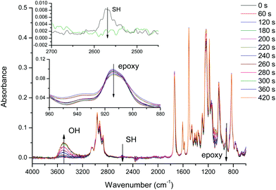 | ||
| Fig. 2 FTIR spectra collected during the curing of DG174S3-0.5 formulation at 80 °C. The insets show the evolution of the thiol and epoxy bands. | ||
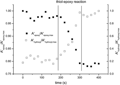 | ||
| Fig. 3 Comparison of the normalized absorbances of the epoxy and hydroxyl bands during the curing of DG174S3-0.5 formulation at 80 °C. | ||
The curing kinetics of the DG174S3-0.5 formulation was studied using a model-free isoconversional methodology in order to analyze the main features of both curing processes and to examine the potential of these off-stoichiometric thiol–epoxy formulations as dual-curable systems. Isothermal and dynamic curing experiments were performed and combined in the analysis in order to obtain reliable kinetics information (see Fig. 2 and 3 in the ESI†). For the analysis of the second curing stage, samples were pre-cured in the DSC before conducting the isothermal/dynamic experiments. Isothermal analysis showed that the first curing stage could reach completion in a few hours at room temperature, while the second curing stage required a higher temperature, in agreement with the dynamic data in Fig. 1. Epoxy group conversion xepoxy instead of calorimetric conversion xDSC was used in the kinetics analysis. The apparent activation energy Ex resulting from the isoconversional kinetics analysis of both curing stages is shown in Fig. 4. In the first curing stage, the changes in Ex with conversion reflect the main features of the thiol–epoxy reaction: (1) an initial Ex around 70 kJ mol−1 reflecting the difficult and slow initiation leading to an induction period, (2) the autocatalytic thiol–epoxy reaction governing the majority of the curing process, with Ex between 60 and 65 kJ mol−1, and (3) the exhaustion of thiol groups leading to a depletion of active species before the epoxy homopolymerization process is activated, with a final increase in Ex. These results are comparable to those reported previously for stoichiometric thiol–epoxy formulations with 1MI.19 Loureiro et al. determined an activation energy of 57.8 kJ mol−1 for the slow initial reaction during the induction period and 88.0 kJ mol−1 for the main process, assuming pseudo-steady state conditions.33 Jin et al.37 reported an apparent activation energy of 64 kJ mol−1 for an uncatalyzed thiol–epoxy reaction and 71 kJ mol−1 for the DBU-catalyzed reaction. There is a clear transition zone between both curing stages, around epoxy conversion 0.5, with a high activation energy of ca. 80 kJ mol−1 that reflects the difficulty in the activation of the epoxy homopolymerization process and would be related to the lower activity of the zwitter-ion in comparison with other alkoxide propagating species. Once the epoxy homopolymerization starts, the apparent activation energy decreases down to 45–50 kJ mol−1 due to the formation of propagating alkoxide species that are more active, and towards the end it increases again. The apparent activation energy values for the epoxy homopolymerization are in good agreement with those reported in the literature for the anionic homopolymerization of epoxides with imidazoles and other tertiary amines.30,44,46
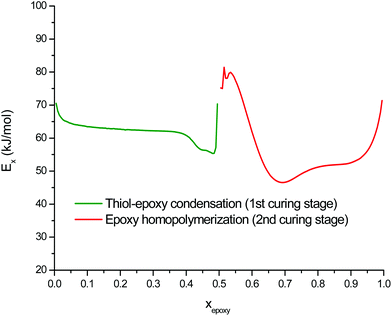 | ||
| Fig. 4 Apparent activation energy of the thiol–epoxy condensation and the excess epoxy homopolymerization during curing of the DG174S3-0.5 formulation, expressed with respect to the epoxy conversion. | ||
With these results a number of simulations were run to determine the stability of the prepared formulations upon storage. It was determined that the prepared formulation DG174S3-0.5 could be stored in a fridge at 5 °C for about 14 hours or more than 1 week at −18 °C before reaching 1% epoxy conversion. The sample would still be in the liquid and could still be processed but with caution, because the induction period would have expired and therefore the curing of the first stage would be shortened.33 Storage for longer periods leading to higher epoxy conversion upon storage would not be advisable due to the autocatalytic nature of the reaction.
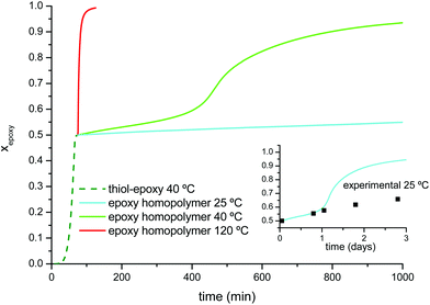
Fig. 5 shows the simulation of the two stages of the curing process under different temperature conditions. The curing of the first stage at 40 °C would reach completion after 75 minutes. If the material was kept at 40 °C, the second curing stage would continue but at a much slower rate, allowing safe and controlled manipulation for a reduced number of minutes. At 120 °C the second stage of the curing process would be complete in just one more hour. If the material was allowed to cool down at 25 °C instead, the intermediate material would remain stable for a longer period of time. In the inset in Fig. 5 the advance of the second curing stage at 25 °C has been compared with experimental points determined from the samples kept in a silicone oil bath at this temperature. An excellent agreement is found on the first day, but deviations become relevant afterwards because of vitrification of the sample as the glass approached the isothermal storage temperature,50 a feature which is not taken into account by the simulation from the isoconversional data obtained at a higher temperature. A safer storage condition before the second curing stage would be to keep the sample in the fridge at 5 °C because the sample would in fact be vitrified (see Table 3) and curing, if any, would be even slower. Similar results would be obtained from the analysis of the formulations with a different thiol![[thin space (1/6-em)]](https://www.rsc.org/images/entities/char_2009.gif) :
:![[thin space (1/6-em)]](https://www.rsc.org/images/entities/char_2009.gif) epoxy equivalent ratio, r. Specific curing schedules and intermediate storage conditions would obviously depend on r and therefore on the relative extent of both curing stages.
epoxy equivalent ratio, r. Specific curing schedules and intermediate storage conditions would obviously depend on r and therefore on the relative extent of both curing stages.
| Formulation | Intermediate | Final | ||||
|---|---|---|---|---|---|---|
| T g (°C) | ΔCp (J g−1 K−1) | T g.FOX (°C) | T g (°C) | ΔCp (J g−1 K−1) | T g.FOX (°C) | |
| DG174S3-1 | 35 | 0.46 | 35 | 35 | 0.46 | 35 |
| DG174S3-0.75 | 23 | 0.50 | 23.8 | 51 | 0.41 | 51.6 |
| DG174S3-0.5 | 9 | 0.54 | 10.7 | 73 | 0.36 | 75.6 |
| DG174S3-0.25 | −5 | 0.55 | −5 | 112 | 0.30 | 113.3 |
| DGEBA of 187 g eq.−1 + 2 phr 1MI | — | — | 181 | ∼0.1 | 181 | |
In conclusion, thiol–epoxy formulations with excess epoxy can be regarded as dual-curable systems with sufficient intermediate stability to make it possible to be used in a variety of two-stage processing situations. A clear advantage of thiol–epoxy formulations catalyzed by tertiary amines such as 1MI or BDMA33 over other low-temperature curing systems such as epoxy–aliphatic amine50–52 or other dual-curable systems12 is the existence of a long induction period due to the slow activation of the reaction and the strong autoacceleration leading to a sharp cure after the induction. This facilitates sample preparation and the application before the curing process starts, and may be valuable for a number of uses requiring a slow or null initial reaction during application such as reaction transfer molding or vacuum infusion. The risk of temperature overshoot in the first curing stage can be minimized by carrying it out at a low temperature, therefore ensuring controllable sequential processing. The curing kinetics at both stages could be further optimized by changing the initiator concentration or by means of using other initiators such as tertiary amines with stronger basicity,37 latent encapsulated imidazoles19 or photolatent bases.21
4.2 Thermal–mechanical properties and network structure
Table 3 shows the results of the DSC analysis of DG174S3-r formulations after the end of the first curing stage and at the end of the curing process. The results of a previously studied DGEBA formulation with 2 phr of 1MI27 have been added for comparison purposes. As observed in other off-stoichiometric dual-curable systems,1 the lower the thiol![[thin space (1/6-em)]](https://www.rsc.org/images/entities/char_2009.gif) :
:![[thin space (1/6-em)]](https://www.rsc.org/images/entities/char_2009.gif) epoxy equivalent ratio the lower the Tg after the thiol–epoxy reaction because of the lower degree of cure. Accordingly, the heat capacity step ΔCp increases with decreasing values of Tg. In contrast, once the epoxy homopolymerization is complete, the Tg increases and the ΔCp decreases with increasing excess of epoxy groups in the formulation, because of the contribution of the epoxy homopolymer network leading to a tighter network structure. Indeed, Table 3 shows that the Tg of a neat epoxy homopolymer27 is about 150 °C higher than that of the neat thiol–epoxy material, hence the observed trend with increasing epoxy excess. It can also be seen that the trend in Tg in the intermediate and final states follows the copolymer rule given by Fox's law,53,54 which makes it possible to estimate the Tg of any material in the intermediate and final stages and use it as a criterion for formulation design.
epoxy equivalent ratio the lower the Tg after the thiol–epoxy reaction because of the lower degree of cure. Accordingly, the heat capacity step ΔCp increases with decreasing values of Tg. In contrast, once the epoxy homopolymerization is complete, the Tg increases and the ΔCp decreases with increasing excess of epoxy groups in the formulation, because of the contribution of the epoxy homopolymer network leading to a tighter network structure. Indeed, Table 3 shows that the Tg of a neat epoxy homopolymer27 is about 150 °C higher than that of the neat thiol–epoxy material, hence the observed trend with increasing epoxy excess. It can also be seen that the trend in Tg in the intermediate and final states follows the copolymer rule given by Fox's law,53,54 which makes it possible to estimate the Tg of any material in the intermediate and final stages and use it as a criterion for formulation design.
The results of the DMA analysis of the fully cured materials shown in Fig. 6 follow the same trend as the results of the DSC analysis. On increasing the excess of epoxy groups in the formulation it is seen how the relaxation of the network, given by the tan![[thin space (1/6-em)]](https://www.rsc.org/images/entities/char_2009.gif) δ peak or the drop in storage modulus E′, shifts to a higher temperature. The modulus in the rubbery state increases and the relaxation peaks become lower and broader, as commonly observed when the crosslinking increases.
δ peak or the drop in storage modulus E′, shifts to a higher temperature. The modulus in the rubbery state increases and the relaxation peaks become lower and broader, as commonly observed when the crosslinking increases.
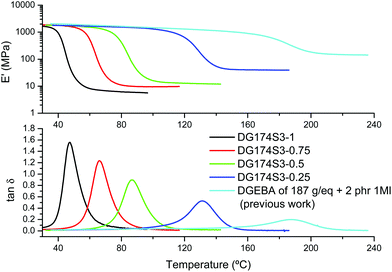 | ||
| Fig. 6 DMA analysis of DG174S3-r formulations in comparison with a neat epoxy homopolymer formulation from a previous work.27 | ||
However, the analysis of the Tg in the final and intermediate states alone is not sufficient to realise the potential application of these materials. A relevant feature of sequential dual-curable systems is the possibility of designing the network structure and properties of the material in the intermediate state depending on the formulation composition and the extent of the first curing process. The thiol–epoxy reaction follows a step-wise network build-up process that can therefore be analyzed using well-established methods.53,55,56 A complete study on the network build-up process including the epoxy homopolymerization stage also is out of the scope of this work, but the analysis could be done using well-established methods such as those described for multi-stage reactions.24,57 Details on the network build-up in epoxy homopolymerization processes can be found in the literature.24,42 The conversion of epoxy groups at gelation xepoxy, gel and the critical stoichiometric ratio rc are two useful parameters that can be used as a tool for preliminary formulation design. Well-known expressions can be found in the literature,53,55 depending on the stoichiometric ratio r and the monomer functionality. However, other relevant network build-up parameters such as the mass-average molecular weight before the gel point Mw, or the effective density of network strands nstrand, the soluble fraction wsol and Mw of the soluble fraction after the gel point, can provide useful and valuable information in terms of application. Details on the procedures and the expressions used for the calculation of the different parameters are found as ESI.† Fig. 4 in the ESI† plots the typical evolution of these parameters during curing, calculated for the DG174S3-0.75 formulation. Preliminary analysis of the gel point conversion of a reduced number of formulations using different methods58 and qualitative evaluation of the sample confirmed the predictions made assuming ideal polycondensation.
Fig. 7 summarizes the effect of the stoichiometric ratio r on key structural parameters at the end of the first stage of the curing process: Mw, xepoxy, gel, wsol and nstrand. For DG174S3-r formulations, the critical stoichiometric ratio rc is 0.5. For r < 0.5, it is seen that all the materials are in the liquid state with increasing Mw as r approaches the value of 0.5. At r = 0.5 the system can gel at the very end of the first curing stage and Mw diverges to infinity. For r > 0.5, all the formulations are gelled after the first curing stage. The soluble fraction wsol and Mw of the soluble fraction decrease and the crosslinking density nstrand increases with the increase in r.
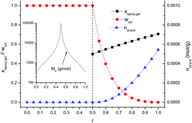 | ||
| Fig. 7 Statistical averages obtained after completion of the first stage of the curing process for the curing of DG174S3-r formulations. | ||
The formulations studied in this work can now be analyzed and discussed on the basis of the results shown in Fig. 7. The evolution of the network structure with r agrees well with the values of Tg in the intermediate state reported in Table 3. Formulation DG174S3-0.25 would be a liquid with a low molecular weight after the first curing stage and, from the application point of view, it would be of interest if it was necessary to have materials with high final Tg (see Table 3) cured in a single-stage process, or else it was necessary to have a liquid after the first curing stage, with a possibility to adjust the viscosity by changing r. Formulation DG174S3-0.5 would be on the verge of gelation, with infinite molecular weight and viscosity but negligible crosslinking, and would be useful as a two-stage adhesive with a solventless first drying stage at room or moderate temperature, having good wetting properties because of the still liquid-like behaviour, but r might be increased slightly to prevent undesired flow during the second curing stage. The DG174S3-0.75 formulation would be a moderately crosslinked material with a solid-like behaviour and a small soluble fraction, therefore allowing their application as tack-free coatings applied on flat substrates that might undergo certain manipulation such as bending without breaking of the coating given its low intermediate Tg (see Table 3) and low crosslinking density (see Fig. 7), reaching the ultimate thermal–mechanical properties after the second curing stage at elevated temperature. Formulation DG174S3-1 would obviously be completely crosslinked after the thiol–epoxy reaction and therefore no two-stage application would be possible.
Changing the thiol![[thin space (1/6-em)]](https://www.rsc.org/images/entities/char_2009.gif) :
:![[thin space (1/6-em)]](https://www.rsc.org/images/entities/char_2009.gif) epoxy equivalent ratio produces some relevant changes in the material after the end of the first and second curing stages, making it possible to adapt these systems to a variety of processing conditions and material requirements. However, the application range of DG174S3-r formulations in dual-curing processes is limited by their overall low Tg and the high critical stoichiometric ratio. By means of introducing a thiol crosslinker and an epoxy with a higher functionality23 it would be possible to reduce the critical stoichiometric ratio and therefore expand the application range of those materials that need to be lightly or moderately crosslinked after the first curing stage with an application as adhesives or coatings with higher ultimate thermal and mechanical properties.
epoxy equivalent ratio produces some relevant changes in the material after the end of the first and second curing stages, making it possible to adapt these systems to a variety of processing conditions and material requirements. However, the application range of DG174S3-r formulations in dual-curing processes is limited by their overall low Tg and the high critical stoichiometric ratio. By means of introducing a thiol crosslinker and an epoxy with a higher functionality23 it would be possible to reduce the critical stoichiometric ratio and therefore expand the application range of those materials that need to be lightly or moderately crosslinked after the first curing stage with an application as adhesives or coatings with higher ultimate thermal and mechanical properties.
4.3 Examples of application
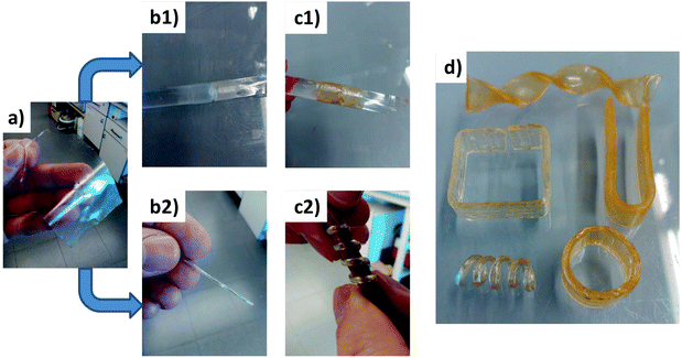
In the literature one can find a number of applications exploiting the benefits from dual-curing processing, such as shape-memory materials, impression materials, holograms1 or dry adhesive bonding.7 In this section, a number of examples are shown in Fig. 8 to illustrate the possibility of creating objects with complex and stable shapes after the second curing stage. A formulation with a thiol![[thin space (1/6-em)]](https://www.rsc.org/images/entities/char_2009.gif) :
:![[thin space (1/6-em)]](https://www.rsc.org/images/entities/char_2009.gif) epoxy equivalent ratio of 0.7 has been prepared. After the first curing stage at 40 °C, the material has a Tg of ca. 21 °C and a low crosslinking density and small soluble fraction (see Fig. 7). It can be easily handled and manipulated and conformed to a number of different shapes that can be fixed after the second curing stage at 120 °C, achieving a more tightly crosslinked network structure with a Tg of ca. 55 °C. Sequence a–b1–c1 in Fig. 8 shows a possible application as pipe joint repair starting from a thin free-standing film after the first curing stage that is wrapped around the two pieces that are joined together. The creation of spring-like objects is illustrated in sequence a–b2–c2, starting from the same thin film, which is rolled and wrapped around a rod before the second curing stage. Fig. 8d shows other shapes that can be obtained starting from a simple and thicker sample by bending or twisting the material before the second curing stage. This particular material has in addition potential shape-memory properties (like other thiol–epoxy thermosets20) that can be exploited in applications in which an actuator with a complex shape is required.
epoxy equivalent ratio of 0.7 has been prepared. After the first curing stage at 40 °C, the material has a Tg of ca. 21 °C and a low crosslinking density and small soluble fraction (see Fig. 7). It can be easily handled and manipulated and conformed to a number of different shapes that can be fixed after the second curing stage at 120 °C, achieving a more tightly crosslinked network structure with a Tg of ca. 55 °C. Sequence a–b1–c1 in Fig. 8 shows a possible application as pipe joint repair starting from a thin free-standing film after the first curing stage that is wrapped around the two pieces that are joined together. The creation of spring-like objects is illustrated in sequence a–b2–c2, starting from the same thin film, which is rolled and wrapped around a rod before the second curing stage. Fig. 8d shows other shapes that can be obtained starting from a simple and thicker sample by bending or twisting the material before the second curing stage. This particular material has in addition potential shape-memory properties (like other thiol–epoxy thermosets20) that can be exploited in applications in which an actuator with a complex shape is required.
5 Conclusions
A new dual-curing system based on thiol–epoxy formulations catalyzed by tertiary amines has been studied in this work. In the presence of a controlled excess of epoxy groups, thiol–epoxy condensation takes place in the first curing stage, while the excess epoxy can only homopolymerize in the second curing stage, once the thiol groups are exhausted. Thiol–epoxy condensation takes place at a much faster rate than epoxy homopolymerization and can even take place at room temperature within a reasonable time, making it possible to effectively separate both curing stages, obtaining materials with stable properties in the intermediate state to permit safe storage and manipulation before the second stage of the curing process is activated at a higher temperature, leading to the material with the desired ultimate properties.Custom-tailoring of the material properties in the intermediate and final stages is possible by changing the excess of epoxy groups in the formulation and therefore the extent of the thiol–epoxy condensation and epoxy homopolymerization reactions. Materials with enhanced thermomechanical properties can be easily obtained by means of using a controlled excess of epoxy monomer, thus overcoming the limitations of thiol–epoxy materials that usually have moderate or low glass transition temperature. It is also possible to design materials that, after the first curing stage, have flowing or non-flowing behaviour, or else have adhesive properties or mechanical strength, allowing easy handling and manipulation, making these systems highly attractive and promising for complex and flexible processing scenarios exploiting the benefits of dual-curable systems like the one presented in this work.
Acknowledgements
The authors would like to thank MINECO (Ministerio de Economía y Competitividad) and FEDER (Fondo Europeo de Desarrollo Regional) (MAT2014-53706-C03-01 and MAT2014-53706-C03-02) and the Comissionat per a Universitats i Recerca del DIUE de la Generalitat de Catalunya (2014-SGR-67).References
- D. P. Nair, N. B. Cramer, J. C. Gaipa, M. K. McBride, E. M. Matherly, R. R. McLeod, R. Shandas and C. N. Bowman, Adv. Funct. Mater., 2012, 22, 1502–1510 CrossRef CAS.
- H. C. Kolb, M. G. Finn and K. B. Sharpless, Angew. Chem., Int. Ed., 2001, 40, 2005–2021 Search PubMed.
- G. Franc and A. K. Kakkar, Chem. Soc. Rev., 2010, 39, 1536–1544 RSC.
- C. E. Hoyle, A. B. Lowe and C. N. Bowman, Chem. Soc. Rev., 2010, 39, 1355–1387 RSC.
- A. Qin, J. W. Y. Lam and B. Z. Tang, Macromolecules, 2010, 43, 8693–8702 CrossRef CAS.
- J. A. Carioscia, J. W. Stansbury and C. N. Bowman, Polymer, 2007, 48, 1526–1532 CrossRef CAS PubMed.
- F. Saharil, F. Forsberg, Y. Liu, P. Bettotti, N. Kumar, F. N. Haraldsson, W. v. der Wijngaart and K. B. Gylfason, J. Micromech. Microeng., 2013, 23, 025021 CrossRef.
- C. F. Carlborg, A. Vastesson, Y. Liu, W. van der Wijngaart, M. Johansson and T. Haraldsson, J. Polym. Sci., Part A: Polym. Chem., 2014, 52, 2604–2615 CrossRef CAS.
- D. Guzman, X. Ramis, X. Fernandez-Francos and A. Serra, RSC Adv., 2015, 5, 101623–101633 RSC.
- H. Peng, D. P. Nair, B. A. Kowalski, W. Xi, T. Gong, C. Wang, M. Cole, N. B. Cramer, X. Xie, R. R. McLeod and C. N. Bowman, Macromolecules, 2014, 47, 2306–2315 CrossRef CAS.
- Y. Jian, Y. He, Y. Sun, H. Yang, W. Yang and J. Nie, J. Mater. Chem. C, 2013, 1, 4481–4489 RSC.
- G. Gonzalez, X. Fernandez-Francos, A. Serra, M. Sangermano and X. Ramis, Polym. Chem., 2015, 6, 6987–6997 RSC.
- N. B. Cramer, C. L. Couch, K. M. Schreck, J. A. Carioscia, J. E. Boulden, J. W. Stansbury and C. N. Bowman, Dent. Mater., 2010, 26, 21–28 CrossRef CAS PubMed.
- A. Mautner, X. Qin, H. Wutzel, S. C. Ligon, B. Kapeller, D. Moser, G. Russmueller, J. Stampfl and R. Liska, J. Polym. Sci., Part A: Polym. Chem., 2013, 51, 203–212 CrossRef CAS.
- R. A. Ortiz, B. A. P. Urbina, L. V. C. Valdez, L. B. Duarte, R. G. Santos, A. E. G. Valdez and M. D. Soucek, J. Polym. Sci., Part A: Polym. Chem., 2007, 45, 4829–4843 CrossRef CAS.
- M. Sangermano, M. Cerrone, G. Colucci, I. Roppolo and R. A. Ortiz, Polym. Int., 2010, 59, 1046–1051 CAS.
- D. Foix, X. Ramis, A. Serra and M. Sangermano, Polymer, 2011, 52, 3269–3276 CrossRef CAS.
- M. Flores, A. M. Tomuta, X. Fernandez-Francos, X. Ramis, M. Sangermano and A. Serra, Polymer, 2013, 54, 5473–5481 CrossRef CAS.
- D. Guzmán, X. Ramis, X. Fernández-Francos and A. Serra, Eur. Polym. J., 2014, 59, 377–386 CrossRef.
- A. Belmonte, D. Guzmán, X. Fernández-Francos and S. De la Flor, Polymers, 2015, 7, 2146–2164 CrossRef CAS.
- C. Seubert and M. Nichols, J. Coat. Technol. Res., 2010, 7, 615–622 CrossRef CAS.
- M. Sangermano, A. Vitale and K. Dietliker, Polymer, 2014, 55, 1628–1635 CrossRef CAS.
- D. Guzmán, X. Ramis, X. Fernández-Francos and A. Serra, Polymers, 2015, 7, 680–694 CrossRef.
- R. J. J. Williams, C. C. Riccardi and K. Dušek, Polym. Bull., 1991, 25, 231–237 CrossRef CAS.
- C. C. Riccardi and R. J. J. Williams, Polymer, 1986, 27, 913–920 CrossRef CAS.
- C. C. Riccardi and R. J. J. Williams, J. Appl. Polym. Sci., 1986, 32, 3445–3456 CrossRef CAS.
- X. Fernandez-Francos, D. Santiago, F. Ferrando, X. Ramis, J. M. Salla, À. Serra and M. Sangermano, J. Polym. Sci., Part B: Polym. Phys., 2012, 50, 1489–1503 CrossRef CAS.
- A. N. Mauri and C. C. Riccardi, J. Appl. Polym. Sci., 2002, 85, 2342–2349 CrossRef CAS.
- C. L. Sherman, R. C. Zeigler, N. E. Verghese and M. J. Marks, Polymer, 2008, 49, 1164–1172 CrossRef CAS.
- X. Fernández-Francos, J. M. Salla, A. Mantecón, À. Serra and X. Ramis, J. Appl. Polym. Sci., 2008, 109, 2304–2315 CrossRef.
- M. S. Heise, G. C. Martin and J. T. Gotro, J. Appl. Polym. Sci., 1991, 42, 1557–1566 CrossRef CAS.
- J. Puig, C. E. Hoppe, L. A. Fasce, C. J. Pérez, Y. Piñeiro-Redondo, M. Bañobre-López, M. A. López-Quintela, J. Rivas and R. J. J. Williams, J. Phys. Chem. C, 2012, 116, 13421–13428 CAS.
- R. M. Loureiro, T. C. Amarelo, S. P. Abuin, E. R. Soulé and R. J. J. Williams, Thermochim. Acta, 2015, 616, 79–86 CrossRef CAS.
- S. K. Ooi, W. D. Cook, G. P. Simon and C. H. Such, Polymer, 2000, 41, 3639–3649 CrossRef CAS.
- X. Fernandez-Francos, W. D. Cook, A. Serra, X. Ramis, G. G. Liang and J. M. Salla, Polymer, 2010, 51, 26–34 CrossRef CAS.
- S. Vyazovkin and N. Sbirrazzuoli, Macromol. Rapid Commun., 2006, 27, 1515–1532 CrossRef CAS.
- K. Jin, W. H. Heath and J. M. Torkelson, Polymer, 2015, 81, 70–78 CrossRef CAS.
- M. Begtrup and P. Larsen, Acta Chem. Scand., 1990, 44, 1050–1057 CrossRef CAS.
- S. G. Tajc, B. S. Tolbert, R. Basavappa and B. L. Miller, J. Am. Chem. Soc., 2004, 126, 10508–10509 CrossRef CAS PubMed.
- M. H. Abraham, P. P. Duce, D. V. Prior, D. G. Barratt, J. J. Morris and P. J. Taylor, J. Chem. Soc., Perkin Trans. 2, 1989, 1355–1375 RSC.
- B. A. Rozenberg, Adv. Polym. Sci., 1986, 75, 113–165 CrossRef.
- X. Fernandez-Francos, Eur. Polym. J., 2014, 55, 35–47 CrossRef CAS.
- M. S. Heise and G. C. Martin, Macromolecules, 1989, 22, 99–104 CrossRef CAS.
- M. S. Heise and G. C. Martin, J. Appl. Polym. Sci., 1990, 39, 721–738 CrossRef CAS.
- F. Ricciardi, W. A. Romanchick and M. M. Joullie, J. Polym. Sci., Polym. Chem. Ed., 1983, 21, 1475–1490 CrossRef CAS.
- I. E. Dell'Erba and R. J. J. Williams, Polym. Eng. Sci., 2006, 46, 351–359 Search PubMed.
- H. J. Flammersheim, Thermochim. Acta, 1998, 310, 153–153 CrossRef CAS.
- S. Swier, G. Van Assche and B. Van Mele, J. Appl. Polym. Sci., 2004, 91, 2798–2813 CrossRef CAS.
- S. Swier, G. Van Assche, W. Vuchelen and B. Van Mele, Macromolecules, 2005, 38, 2281–2288 CrossRef CAS.
- D. Santiago, X. Fernàndez-Francos, X. Ramis, J. M. Salla and M. Sangermano, Thermochim. Acta, 2011, 526, 9–21 CrossRef CAS.
- E. Frulloni, M. M. Salinas, L. Torre, A. Mariani and J. M. Kenny, J. Appl. Polym. Sci., 2005, 96, 1756–1766 CrossRef CAS.
- S. Paz-Abuin, A. Lopez-Quintela, M. Varela, M. Pazos-Pellin and P. Prendes, Polymer, 1997, 38, 3117–3120 CrossRef CAS.
- J. P. Pascault, H. Sautereau, J. Verdu and R. J. J. Williams, Thermosetting polymers, Marcel Dekker, New York, 2002 Search PubMed.
- T. G. Fox, Bull. Am. Phys. Soc., 1956, 1, 123 CAS.
- D. R. Miller, E. M. Valles and C. W. Macosko, Polym. Eng. Sci., 1979, 19, 272–283 CAS.
- D. R. Miller and C. W. Macosko, Macromolecules, 1976, 9, 206–211 CrossRef CAS.
- G. P. J. M. Tiemersma-Thoone, B. J. R. Scholtens, K. Dušek and M. Gordon, J. Polym. Sci., Part B: Polym. Phys., 1991, 29, 463–482 CrossRef CAS.
- X. Fernández-Francos and X. Ramis, Eur. Polym. J., 2015, 70, 286–305 CrossRef.
Footnote |
| † Electronic supplementary information (ESI) available. See DOI: 10.1039/c6py00099a |
| This journal is © The Royal Society of Chemistry 2016 |

