
 Open Access Article
 This Open Access Article is licensed under a Creative Commons Attribution-Non Commercial 3.0 Unported Licence
Introducing electrical conductivity to metal–organic framework thin films by templated polymerization of methyl propiolate†
Beren
Sen
a,
Jaciara C. C.
Santos
 a,
Ritesh
Haldar
a,
Qiang
Zhang
a,
Tawheed
Hashem
a,
Peng
Qin
a,
Ying
Li
a,
Frank
Kirschhöfer
a,
Gerald
Brenner-Weiss
a,
Hartmut
Gliemann
a,
Lars
Heinke
a,
Christopher
Barner-Kowollik
bc,
Alexander
Knebel
*a and
Christof
Wöll
*a
a,
Ritesh
Haldar
a,
Qiang
Zhang
a,
Tawheed
Hashem
a,
Peng
Qin
a,
Ying
Li
a,
Frank
Kirschhöfer
a,
Gerald
Brenner-Weiss
a,
Hartmut
Gliemann
a,
Lars
Heinke
a,
Christopher
Barner-Kowollik
bc,
Alexander
Knebel
*a and
Christof
Wöll
*a
aInstitute of Functional Interfaces, Karlsruhe Institute of Technology, Hermann-von-Helmholtz-Platz 1, 76344, Eggenstein-Leopoldshafen, Germany. E-mail: alexander.knebel@kit.edu; christof.woell@kit.edu
bCentre for Materials Science, School of Chemistry and Physics, Queensland University of Technology (QUT), 2 George Street, QLD 4000, Brisbane, Australia
cInstitute of Nanotechnology, Hermann-von-Helmholtz-Platz 1, 76344 Eggenstein-Leopoldshafen, Germany
First published on 13th November 2020
Abstract
We herein present a case study on the templated, Pd-catalyzed polymerization reaction of methyl propiolate in the confined pore space of three different surface anchored metal–organic framework (SURMOF) systems in order to introduce electrical conductivity to MOF thin films and provide predictions for potential device integrations. To gain comprehensive insight into the influence of the template on polymerization, we chose Cu(bpdc), Cu2(bdc)2(dabco) and HKUST-1 because of their different types of pore channels, 1D, quasi-1D and 3D, and their free pore volumes. Well-defined MOF thin films were prepared using layer-by-layer deposition, which allows for the application of several characterization techniques not applicable for conventional powder MOFs. With SEM, AFM, XRD, MALDI-ToF/MS, ToF-SIMS and QCM, we were able to investigate the behaviour of the polymer formation. For lower dimensional pore channels, we find a depot-like release of monomeric units leading to top-layer formation determined by desorption kinetics, whereas for the 3D channels, quick release of an excess amount of monomers was observed and polymerization proceeds perfectly. Despite polymerization issues, control over the maximum chain lengths and the molecular weight distribution was achieved depending on the dimensionality of the pore systems. For the HKUST-1 system, polymerization was optimized and we were able to measure the electrical conductivity introduced by the conjugated polymer inside the channels.
Introduction
In recent years, metal–organic frameworks (MOFs) have been used as templates for polymerization reactions of different kinds of monomers, thus exploiting the MOF pore space to control and steer the polymerization process.1–3 We herein present a comparative study not only focusing on polymerization control but also on the introduction of electrical conductivity to MOFs. MOFs, as a class of ordered crystalline porous materials consisting of inorganic metal ions and bridging organic linkers, are versatile materials but mostly insulators.4–7 The diversity of metal ions and linker molecules provides the possibility to tune pore sizes, intrinsic surface areas, pore windows, pore geometries and also pore surface functionalities.8,9 Recently, layered 2D conductive MOFs have been developed as high-performance electrode materials.10–12 However, the cavities of MOFs open up highly interesting spaces for different kinds of applications, such as catalysis,13 gas storage,14 separation15,57 and environmental remediation.16 Most important for this study is that the pores and pore-channels of MOFs provide confined space for chemical reactions, e.g. polymerization, to occur.13,17–20 The formation of polymers inside the pores of MOFs has been reported for methacrylate,21 aromatic acetylene,22 vinyl monomers,23,24 substituted acetylenes,25 graphene nanoribbons26 and polyacrylonitrile.27 In the present study, we focused on the polymerization of methyl propiolate (MP) to the conjugated poly(methyl propiolate) to introduce conductivity to SURMOF (surface anchored MOF) systems (cf.Fig. 1).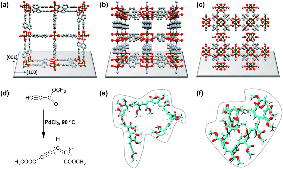 | ||
| Fig. 1 Visualization of the structure of (a) 1 (SURMOF-2, Cu(bpdc)), (b) 2 (Cu2(bdc)2(dabco)), and (c) 3 (HKUST-1, Cu(btc)). Color scheme: C (gray), O (red), N (purple), and Cu (green). (d) MP polymerization catalyzed by PdCl2. (e) Molecular dynamics simulation of the (e) initial structure of poly(methyl propiolate) and the (f) final coiled structure of poly(methyl propiolate). | ||
First of all, confining polymerization reactions inside the pores of MOFs can lead to several advantages over the conventional bulk polymerization reactions. The key factors involved in using MOFs as templates are (i) the controllability of the molecular weight of polymer chains,28,29 (ii) the morphology and arrangement of polymers,30–32 (iii) the reduction of branching during polymerization23 and (iv) the pre-determination of the reaction direction by encapsulation of monomers.28
SURMOF thin films have rarely been used for polymerization reactions33–35 and are known to have several benefits over the conventional powdered form of MOF materials: for MOF thin films non-conventional characterization techniques can be applied to follow the polymerization reaction, due to the uniformity of the MOF film.34–40 Here, we show that SURMOFs can be used as model systems to monitor the controlled polymerization reaction utilizing 3 different pore systems of the studied MOFs.
Pd-catalysed polymerization of methyl propiolate, a substituted acetylene, was performed in 1D and 3D nanochannels using three different SURMOF model systems: Cu(bpdc) (1) (bpdc = 4,4-biphyenyldicarboxylic acid), Cu2(bdc)2dabco (2) (bdc = 1,4-benzenedicarboxylate, dabco = 1,4-diazabicyclo(2.2.2)octane), and HKUST-1 (3) (Hong Kong University of Science and Technology-1). Interestingly, the length of the polymer formed by the polymerization reaction was found to depend on the particular type of MOF used, with a maximum length of n = 22 in the channels of 1, whereas in the channels of 2, the polymer led to a length of up to n = 19. In the 3D channels of 3, HKUST-1, the polymers were found to have a length of up to n = 23, the same as that in bulk polymerization. We carried out comprehensive studies identifying the benefits and drawbacks related to the use of 1D and 3D pore systems for polymerization reactions. We find depot-effects by loading and unloading experiments with the QCM sensors, which show significantly different desorption kinetics between species from the lattices of MP; with 1 leading to a top-layer formation in the former case, and successful polymer formation in the latter case for 3.
Experimental
Chemicals
Copper acetate monohydrate (≥98%), palladium chloride (99%), MUD (11-mercapto-1-undecanol, 97%), bdc (1,4-benzenedicarboxylate, 98%), 16-mercaptohexadecanoic acid (MHDA), dabco(1,4-diazabicyclo(2.2.2)octane (≥99%) and DCTB (trans-2-[3-(4-tert-butylphenyl)-2-methyl-2-propenylidene]malononitrile, ≥99%), hydrochloric acid (37%), glacial acetic acid, tetrahydrofuran (THF, (≥99.9%)) and chloroform (≥99.5%) were purchased from Merck, Germany. Methyl propiolate (99%) was purchased from Alfa-Aesar, Germany. Absolute ethanol (≥99.8%) was purchased from VWR chemicals. The substrates used for SURMOF synthesis consisted of a 100 nm Au/5 nm Ti metal bilayer deposited on p-doped (100) Si wafers and plain p-doted (100) Si wafers. The Au surface was functionalized by a self-assembled monolayer of MUD before SURMOF synthesis. All chemicals were used as received, without further purification.X-ray diffraction (XRD)
X-ray diffraction was performed using a D8 ADVANCE Bruker AXS diffractometer with Cu Kα radiation (λ = 1.5418 Å) in θ–θ geometry with a position sensitive LynxEye detector and a variable divergence slit. The samples were investigated with a scan speed of 1 s and an increment of 0.02° per step.Modelling the SURMOF structures by loading MP and PdCl2
The software package BIOVIA Material studio 2018 was used to create appropriate models of MP and PdCl2 loaded 1, 2 and 3 MOF structures. Each unit cell was filled with one MP and PdCl2. The structure models were then used to simulate XRD patterns for comparison with the experimental data. No structural optimization using e.g. force fields was carried out for these model structures.Simulation of poly(methyl propiolate)
Force field simulations of the coiling behavior of polyMP with n = 20 were performed using CgenFF version 4.0 with a CHARMM36 force field being applied.41–44 Coiling simulation started with the steepest descent minimization, followed by a Canonical ensemble (NVT) simulation of 100 ps using a V-rescale thermostat, and then by an NVT simulation of 10 ns using a Nosé–Hoover thermostat. All simulations were performed using GROMACS 2019.2 with periodic boundary conditions being applied.ToF-SIMS (time-of-flight secondary ion mass spectrometry)
ToF-SIMS experiments were performed on a TOF·SIMS5 instrument (IONTOF GmbH, Münster, Germany). The base pressure is 7 × 10⁻⁹ mbar. Bi3+ ions, 25 keV, 0.27 pA at 125 μs cycle time, were used as primary ions; Ar1200+ ions, 0.25 keV, 0.7 nA, were used as sputter ions. To remove trace amounts of physisorbed MP and to differentiate them from thicker layers of polyMP, dynamic SIMS spectra were recorded in the non-interlaced mode. Therefore, a 700 × 100 μm2 crater was eroded (3 scans followed by 1 s pause), and a concentric field of view of 500 × 500 μm2 was analyzed (3 frames) until a total sputter time of 600 s was achieved.MALDI-ToF/MS
MALDI-ToF/MS experiments were carried out using a 4800 MALDI-ToF/ToF mass spectrometer (AppliedBiosystems/MDS SCIEX, Foster City, CA) equipped with a Nd:YAG pulsed laser (355 nm wavelength with <500 ps pulses and 200 Hz repetition rate) and using the 4000Series Explorer (V3.5.3) and DataExplorer (V 4.9) software. Data acquisition was performed in the reflector positive ion mode. The selected acquisition range was 600 to 2000 m/z. Each mass spectrum showed an average of 1000 laser shots over the entire spot.Prior to the MALDI-ToF/MS analysis, the SURMOF thin films were dissolved by immersion in a solution of 50 μL of acetic acid mixed with 0.4 mL of ethanol, retaining the polymer chains. To prepare a mixture solution for MALDI-ToF/MS analysis, 0.5 μL of the resulting liquid was mixed with 0.5 μL of matrix solution consisting of 10 mg of DCTB in 1 mL of THF. After digestion of the SURMOF, 5 μL of the resulting solution was spotted and air-dried on the MALDI target.
SEM and EDXM
A TESCAN Vega 3 with a tungsten filament electron source was used for scanning electron microscopy (SEM) analysis. Images were recorded using a working distance of 6–14 mm, with an emission voltage of 8–10 kV. For energy dispersive X-ray spectroscopy (EDXS) and mapping (EDXM), a Bruker XFlash Detector 610 M was used, always with an emission voltage of 10 kV. To prevent artifacts caused by electrical charging of the SURMOFs, the samples were sputtered with a Bal-Tec MCS 010 coating system using an Au–Pd target. Regarding the choice of the target, we found that the determination of catalytic Pd amounts in the MOF sample is not possible with sufficient accuracy and the underlying Au-layer in HKUST-1 is not necessary to quantify, and thus the Au–Pd target was used for the best possible resolution.AFM
The AFM micrographs were recorded at room temperature using a Bruker Dimension Icon Atomic Force Microscope in alternating current mode (AC mode) in air using MikroMasch NSC15 probes, with a scan rate of 0.6 Hz and 400 scan lines. A minimum number of modifications are performed in the raw data. Pristine and polymerized samples were sonicated in 1 mM diluted hydrochloric acid solution for 30 minutes in order to remove the SURMOFs. Then, the solution containing the polymer was dropcast onto a smooth Si substrate and investigated by AFM.45Electrical conductivity measurements
The electrical conductivity of the sample was investigated by 2-probe current–voltage measurements using a Keithley 2635B Source Meter. The sample was grown on interdigitated gold electrodes on glass substrates from Metrohm. The gap width between the electrodes increased to 5 μm, with a total gap length of 3.38 m. Electrical characterization was carried out under a pure nitrogen atmosphere at room temperature (298 K). Before the experiment, the sample was equilibrated under the nitrogen atmosphere for more than one hour, in order to allow all volatile guest molecules to desorb from the pores. As a reference to the polymer-filled HKUST-1 sample, an empty HKUST-1 sample was used. For more details of the experimental setup used for conductivity measurements, see the study by Garg et al.46Synthesis of SURMOF templates
In this study, thin films of Cu(bpdc) (1), Cu2(bdc)2(dabco) (2) and HKUST-1 (3) were selected as templates for methyl propiolate polymerization. Thin films of Cu(bpdc) (1) and HKUST-1 (3) were grown using layer-by-layer deposition via the spray coating method.33 Si substrates were functionalized by UV treatment for 30 minutes prior to synthesis, whereas the Au substrates were functionalized using MHDA (16-mercaptohexadecanoic acid) solution. For MHDA functionalization, gold substrates were immersed in 1 mM ethanolic MHDA solution for 72 h. The activated substrates for 1 were mounted on the sample holder and subsequently sprayed with a 1 mM ethanolic solution of Cu(CH3COO)2·H2O and a 0.2 mM ethanolic solution of 4,4-biphyenyldicarboxylic acid for 30 spray cycles. The thin films of 3 were also prepared using the same method. The metal solution was the same as that of 1, whereas the linker solution was 0.2 mM 1,3,5-benzenetricarboxylic acid in ethanol.Thin films of Cu2(bdc)2(dabco) (2) were grown on Au and Si substrates using layer-by-layer deposition via a pump system.47 Prior to SURMOF synthesis, the gold substrates were functionalized by SAMs deposited from a MUD (11-mercapto-1-undecanol) solution.48 For MUD functionalization, the gold substrates were immersed in 1 mM ethanolic MUD solution for 24 h. After functionalization, the Au substrates were rinsed with pure ethanol and dried under a N2 stream. 1 mM Cu(CO2CH3)2·H2O as the metal solution and a mixture of 0.1 mM bdc(1,4-benzenedicarboxylate) and dabco(1,4-diazabicyclo(2.2.2)octane) as the linker solution were used in order to grow 2. After functionalization of the substrates, they were placed inside the sample holder of a pump system.49 During synthesis, the substrates were immersed in the ethanolic copper acetate solution for 10 minutes, whereas the immersion time in the linker solution was 20 minutes. 40 deposition cycles were run at 60 °C.
Quartz crystal microbalance
A Q-Sense E4 Auto4 device was used with a Q-Sense QCM sensor, diameter 14 mm, thickness 0.3 mm, AT cut, and fundamental frequency 4.95 MHz. SURMOF systems 1 (deposited on the Au coated QCM sensor) and 3 (deposited on the SiO2 coated QCM sensor) were synthesized using the same procedure as that described above for 40 cycles. Temperatures of 25 °C and 40 °C were used for adsorption and desorption experiments. Flowrates for Ar and N2 were always kept at 100 ml min−1 using a mass flow controller. The samples were activated under Ar-flow at 40 °C overnight, cooled down to 25 °C and measured under N2-flow. For dosing of MP, N2 was bubbled through pure MP until a steady state is reached, further followed by desorption with pure N2. For complete desorption from the frameworks, heating to 40 °C was necessary.Methyl propiolate loading and polymerization in SURMOFs
Before the loading of methyl propiolate (MP), SURMOFs were activated under vacuum at 80 °C for 6 hours in order to completely remove the guest solvents. For the loading step, 400 μL of methyl propiolate was mixed with a trace amount of palladium chloride (PdCl2) catalyst.50 This solution was dropcast onto the activated SURMOFs and left undisturbed for 2 hours in a glass vial at room temperature. To remove the residual monomer, the samples were washed with chloroform prior to polymerization. Afterwards, the MP loaded SURMOFs (MP@1, 2, 3) were placed in an oven at 90 °C for 5 hours for the polymerization of the MP in the SURMOFs (polyMP@1, 2, 3). Finally, the samples were washed with chloroform to remove the unreacted monomer and the excess polymer from the surface for further characterization.Bulk polymerization of MP was performed with a slight difference to that reported in the literature.50 In order to compare the chain length of polyMP in bulk to that synthesized in the pores of the SURMOFs, bulk polyMP was prepared by mixing 400 μL of MP with a trace amount of PdCl2. The mixture was placed in an oven at 90 °C for 5 hours.
Results and discussion
Three different SURMOF systems were investigated as host materials for methyl propiolate (MP) polymerization, Cu(bpdc), also called SURMOF-2 (1), Cu2(bdc)2(dabco) (2), and HKUST-1 (3). Fig. 1a, b, c shows the structures of 1, 2 and 3, respectively, along with the reaction mechanism for coupling the MP units to yield poly(methyl propiolate) (polyMP) in the presence of PdCl2. The structure of the polymer is shown in Fig. 1e and f. Systems 1 and 2 were deposited on Si wafers using the layer-by-layer synthesis procedure; in the case of 3, gold-coated Si-wafers were used. The layer-by-layer procedure is well known to yield very uniform and controllable MOFs with a well-defined orientation on the substrate. SURMOF system 1, which is a member of the SURMOF-2 isoreticular series,33 exhibits a sheet like structure, expressing 1D pore channels that are aligned parallel to the supporting Si-wafer (Fig. 1). The interlayer distance between the planes in structure 1 amounts to 5.6 Å.512 has a 3D pore system, with large square shaped channels of 7.5 × 7.5 Å perpendicular to the supporting layer. However, in 2, the cubic pore windows oriented parallel to the support have rather small openings with a size of only 3.8 × 4.7 Å (ref. 52) (cf.Fig. 1b). We believe that these openings are too small to allow for diffusion of MP (kinetic diameter 6.2 Å), and therefore, we consider it as a quasi-2D framework for the polymerization of MP. SURMOF system 3 is an already well-studied and known system, perfect for this comparative study, with a 3D pore-system exhibiting pore windows with diameters of 9 Å and 6 Å and 3 different cavities with diameters of 14 Å, 11 Å and 5 Å.53 The smallest cavity in 3 is not considered relevant for the polymerization reaction due to the size of MP. Nevertheless, there is sufficient space in HKUST-1 to allow for the formation of continuous polyMP. The polymerization of MP was catalysed by using small amounts of PdCl2. Trace amounts of PdCl2 were first added to pure MP, which was then loaded subsequently into the SURMOF. What all of the MOF systems investigated in this study have in common is that the linkers are connected via Cu-paddle wheel type secondary building units.Estimates of the sizes of polymer coils formed from polyMP were obtained on the basis of molecular dynamic simulations (Fig. 1e and f), using a long polymer of 20 monomer units. The simulations indicate the formation of coils, as expected, with an average radius of gyration that equals 0.66 nm. The analysis of the coil structure showed that the last frame yielded dimensions of 1.5 × 1.9 × 1.8 nm. On the basis of these simulations, we expect that the 22 coils formed should fit into the pores of all three MOF systems.
Upon loading and polymerization, XRD patterns were recorded as shown in Fig. 2. They reveal that MP loading has only a weak influence on the reflexes. Nonetheless, small form factor variations as well as changes in the intensity ratios are observable. This experimental observation is consistent with the simulations obtained for MOF models where the pore contained 1 MP or PdCl2 molecule, leading to comparable results: the modelled MP loading provides an estimation of the experimental polyMP XRD data. The modelled patterns of MP and PdCl2 loading are shown separately for 1, 2 and 3 and the changes are observed in the XRD patterns as shown in Fig. S1.† From the simulated MP@1, MP@2 and MP@3 XRD patterns (Fig. S1†), it can be observed that the crystallographic changes are consistent with the experiments (cf.Fig. 2). For the SURMOF system 1, the (001) and (002) peaks disappeared after polymerization, while a new (210) peak emerged. According to modelling, after loading of MP and PdCl2 into 1, the (210) reflex appears (Fig. S1†). Comparing the experimental and simulated data of the samples, we conclude that the appearance of the reflex for the lattice plane (210) is attributed to the successful polymerization (Fig. S1a†). For 2, the loading with MP and the subsequent polymerization to polyMP@2 showed changes in the reflex intensities, together with introduced crystal strain, and visible changes of the form factors (Fig. 2b).
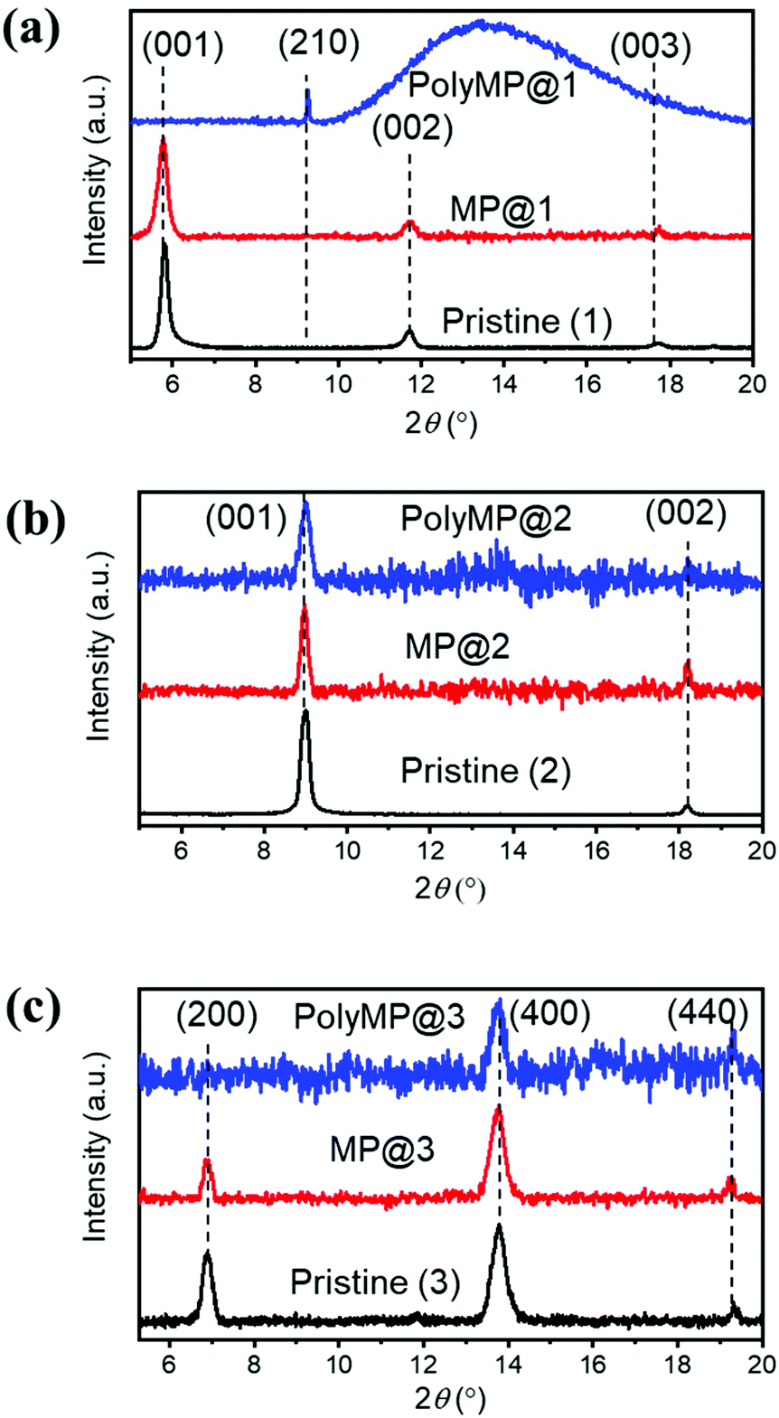 | ||
| Fig. 2 Out-of-plane XRD patterns of (a) 1, (b) 2 and (c) 3 in the pristine state (black), after MP loading (red) and after polymerization (blue) with normalized intensities. Changes in the form factors upon loading are visible, as well as intensity differences. The detailed modelling of the structure upon monomer loading has been performed and can be found in the ESI.† | ||
The XRD pattern of 3 showed that the (200) peak disappeared, whereas the (400) peak was still observable after polymerization. After MP loading, the form factors changed as well (Fig. 2c). In modelling the structure of 3, the effects found experimentally are stronger, yet a comparable change is observed. After the loading of MP into SURMOF system 3, the intensity of the (200) peak is decreased (Fig. S1c†). From all XRD patterns, it can be concluded that MP loading and polymerization have a strong effect on the reflex intensities and form factors, but the MOF structure remains crystalline.
Morphological studies of the SURMOFs upon polymerization
The cross-sections of pristine and polymerized samples of 1, 2 and 3 were characterized by scanning electron microscopy (SEM) and energy dispersive X-ray spectroscopy and mapping (EDXS and EDXM) in order to assess if visible changes appear after polymerization (cf.Fig. 3). Further characterization using mass spectroscopy was important to investigate the products of the polymerization reaction, which is given in Fig. 5.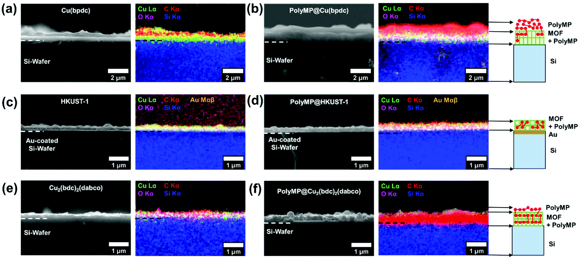 | ||
| Fig. 3 SEM images and the corresponding EDXM of (a) pristine 1, (b) polyMP@1, (c) pristine 3, (d) polyMP@3, (e) pristine 2, and (f) polyMP@2. For 1 and polyMP@1, the formation of a clear, strong top-layer is visible, whereas for 3 and polyMP@3, no top-layer formation is observed. Note that due to the strong intensity of carbon from (e) to (f), the MOF signal almost diminishes, but from the thickness difference, we assume the formation of a small top-layer. The cartoons on the right side of (b), (d) and (f) show the observations of polyMP formation. | ||
The SEM pictures and EDXM in Fig. 3 show that the pristine SURMOF layers are all close to 200–300 nm in thickness. After the polymerization reaction, a number of changes can be observed. It can be clearly seen from SEM analysis together with EDXM that a thick layer of polymer covers the surface of 1 (Fig. 3a and b) after the polymerization reaction. We subsequently evidence that monomers slowly desorbing from the lattice of 1 yield a surface covering polymer film, the SURMOF thin film. This diffusion out of the SURMOFs could result from the fact that the pore channels of 1 are aligned parallel to the underlying Si-wafer, making the desorption kinetics slower than that of e.g.3 (Fig. 3c and d) and resulting in a depot-like effect. The EDX spectra of the SURMOF films (Fig. S2–S4†) show an increase in the C-signal to Cu-signal ratio, which is evidence for polymerization inside the MOFs in all cases, and an overall effect after polymerization was expected for all samples. With the distribution of the carbon signal in the EDXM, we can see where the polymer is formed, which is definitely a surface covering top-layer for 1 and 2, and is not observed for 3 (Fig. 3).
Investigations show that the thickness of the polymer top-layer of 1 has a linear dependency on the thickness of the SURMOFs (Fig. S5†), which is also attributed to the slow and steady desorptive release of MP from the framework of 1, as can also be shown by quartz crystal microbalance (QCM) experiments (Fig. 4c and Fig. S6†). For 3, this phenomenon of a polymer top-layer is not found. Loading experiments of MP in SURMOFs 1 and 3 were performed in order to determine the adsorption/desorption kinetics of the thin films (Table S1†), where the difference is observable in the normalized mass change over the time diagram in Fig. 4c. The desorption kinetics of MP from 3 is much faster than that of MP from 1 (Fig. 4, Fig. S6 and Table S1†). Thus, the desorption kinetics of 1 can be determined from the release of the monomers from a depot, which gives coherent results regarding the top-layer formation observed in SEM images (cf.Fig. 3b and 4a). The depot-effect occurs due to very slow time constants of T0.5 ≈ 2 min and T0.8 ≈ 144 min for 1, so a top layer can be formed through long term release of MP, whereas MP molecules were desorbed within T0.8 ≈ 2.6 min in 3 during burst-type release, which makes top-layer formation impossible (cf. Table S1† and Fig. 3d). The XRD patterns and SEM cross-sections of the SURMOFs on the QCM sensors are shown in Fig. S7.†
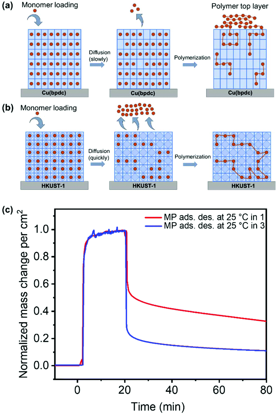 | ||
| Fig. 4 Schematic diagram showing the depot effect of (a) MP diffusion from 1 and (b) quick release from the framework of 3, followed by polymerization. In (c), the normalized mass change from the adsorption and desorption of MP on 1 and 3 measured using a QCM is shown. | ||
For 2, we observe that a thinner layer of the polymer covers the surface (Fig. 3e and f). We assume that SURMOF system 2, due to its quasi-1D pore network (and because of the kinetic diameter of MP), has a release kinetics in-between the pore-systems 1 and 3. Thus, desorption kinetics also triggers top-layer formation. Nevertheless, it seems less limited than for 1 from SEM analysis. In EDXM, no differentiation between the polymer and the MOF is observable for 2 (Fig. 3f), leading to the assumption that the polymer is additionally equally well distributed inside the pores of 2 as is the case for 3.
However, for 3 as the desired result, not even a thin top-layer is observable from the SEM images or EDXM and thus no covering of the surface after polymerization (cf.Fig. 3c and d). From EDXM we observe that, for pristine 3, the carbon signal is very low, so that the C-signal was increased for visualization (resulting in the C-signal artefacts in the background) (Fig. 3c). In Fig. 3d, the C-signal has the same strength as that of the Cu-signal, with no observable top-layer, which is already an indicator for successful polymerization inside the pores of 3. However, all quantitative EDX spectra can be found in the ESI 2–4.†
The polymer morphology was further observed using AFM, which is shown in Fig. 5. Fig. 5a and b show the polymer from bulk synthesis, deposited on a flat Si substrate, whereas Fig. 5c and d show the polymer obtained from SURMOF system 3 after chemical decomposition followed by a similar deposition procedure on a Si substrate. It can be concluded that the bulk polymer forms large, spherical, agglomerated particles. The polymer formed in the SURMOF looks completely different, and it appears more like a polymer film containing fibers and very tiny, agglomerated particles.
 | ||
| Fig. 5 AFM images of the (a, b) bulk polymer and (c, d) polymer from the SURMOF deposited on a smooth surface. | ||
Molecular weight distribution of polyMP formed in SURMOFs & depth profile analysis of the monomer loaded and polymerized samples
MALDI-ToF/MS was used in order to determine the chain lengths and molecular weight distribution of the polymers formed in 1, 2 and 3. Therefore, polyMP@1, polyMP@2 and polyMP@3 were immersed in a mixture of ethanol and acetic acid solution in order to dissolve the SURMOF systems. The solution containing polyMP from the samples was analyzed by MALDI-ToF/MS. The molecular mass of a monomeric MP unit is 84.07 g mol−1, which is clearly observable in the size distribution of the polymer in the mass spectrum. The masses shown in the spectra (Fig. 6a–c) are sodium adduct masses. Chains of polyMP are observed in 1 with a maximum length of up to n = 22 (Fig. 6a), in 2 with a length of up to n = 19 (Fig. 6b) and in 3 with a length of up to n = 23 (Fig. 6c). The full isotopic pattern overlays are shown in Fig. S8,† while the isotope patterns of peak n = 8 for the 3 systems are shown in Fig. S9.† For the bulk polymer formed by the reaction in solution, which we used as a comparative sample, a maximum chain length of up to n = 23 for this short-chain polymer is observable (Fig. S10†). With this in mind, in the context of SEM analysis (Fig. 3) and polymer coil MD simulation (Fig. 1f), we can conclude that the pore-volume has a strong influence, especially in 1D pore-channels, on the chain length and thus, on the molecular weight distribution. If the polymer is formed mainly on the top-layer (as for polyMP@1), we clearly expect the molecular weight distribution to equalize the molecular weight distribution of the bulk. Surprisingly, we still get a comprehensive result for polyMP@1, with n = 22, underlining the thesis of confined polymerization. The polymerization of polyMP@2 in the 1D channels of 2 was much more successful, yielding only n = 19. Interestingly, polyMP@3 (Fig. 6c) gives the same weight distribution as that of the bulk polymer, but without top-layer formation. | ||
| Fig. 6 (a) MALDI-ToF spectrum of (a) polyMP@1, (b) polyMP@2, and (c) polyMP@3 after dissolution in acetic acid/ethanol, depth integrated ToF-SIMS data showing the main fragment of the polyMP repeating unit of (d) MP@1 (red) and polyMP@1 (blue), (e) MP@2 (red) and polyMP@2, and (f) MP@3 (red) and polyMP@3, three different analysed spots on each sample. | ||
The results obtained in a previous study on polymerization in SURMOF-2 (here system 1) only yielded oligomers. Here, we are able to increase the chain length up to the bulk polymer chain length of n = 19–23. The resulting polymer in the previous study was rather short with a maximum of n = 4 for terthiophene and n = 9 for EDOT34 suggesting that using in-plane 1D frameworks, a polymerization reaction is always highly restricted by the diffusion of the species inside the pore system, e.g. in this case yields depot-like release and a subsequent confined polymer and bulk polymer mixture. When going to higher dimensional pore systems, the polymerization reaction is becoming more comparable to bulk polymerization.
To further investigate the influence of the SURMOF template for the polymerization reaction, depth integrated spectral analysis and depth profile analysis were done by ToF-SIMS on all samples in order to validate the formation of the polymer inside the pores of SURMOFs. Therefore, mass spectra of the monomer loaded and polymerized samples are shown in Fig. 5. The depth integrated spectra are shown for the C4H3O2− monomeric units from 1 (Fig. 6d), 2 (Fig. 6e) and 3 (Fig. 6f). In the ToF-SIMS analysis of the monomer loaded samples for 1, 2 and 3, only rather small amounts of C4H3O2− were found, since under UHV conditions the monomer is easily desorbing from the lattice. However, due to a small amount of “sticky” monomer molecules that do not easily desorb from the SURMOF lattices (cf. Fig. S6†), some residual monomers could be detected. Furthermore, it was observed in the depth integrated images that 63Cu−, 65Cu− and C4H3O2− are laterally correlated for the polymerized samples of 1 (Fig. S11†), 2 (Fig. S12†) and 3 (Fig. S13†), respectively. From the ToF-SIMS depth analysis, we can conclude that in our case, even if a top-layer is formed, the polymerization takes place inside the pores for all cases. The depth profiles of the polymerized samples are shown in Fig. S14.† From the ToF-SIMS depth profiles (Fig. S14†) normalized on the Cu-signal coming from the MOF, it can be concluded that there is a gradient starting at the top of each SURMOF layer with the highest monomer content, which fades out towards the underlying substrate (Si or Au signal).
Electrical conductivity of HKUST-1 after polymerization
The goal of the present study is the formation of a polymer film completely embedded in a SURMOF. The best result obtained in conductivity measurements (cf.Fig. 7) through polyMP@SURMOF systems could only be achieved for polyMP@3, whereas for the other systems the formation of a thick layer covering the substrate was observed, making them unsuitable for reliable measurement. To further characterize the successful case, the lateral conductivity of 3 and polyMP@3 was measured using interdigitated Au-electrodes. The current–voltage curves of the sample are shown in Fig. 7. The FTIR spectra of 3, MP@3 and polyMP@3 used in this measurement are shown in Fig. S15.† The current is proportional to the voltage indicating ohmic conduction behavior. While the polymer-loaded sample shows a current of almost 3.6 μA at 3 V, the empty sample shows only a current of 3.3 pA. A sample thickness of 200 nm corresponds to a conductivity of 9 μS m−1. This is about 6 orders of magnitude larger than the conductivity of the empty SURMOF system 3, where we obtained a value of 8 pS m−1, which is in line with other published values for SURMOFs and for empty HKUST-1 and loaded with 7,7,8,8-tetracyanoquinododimethane.54–56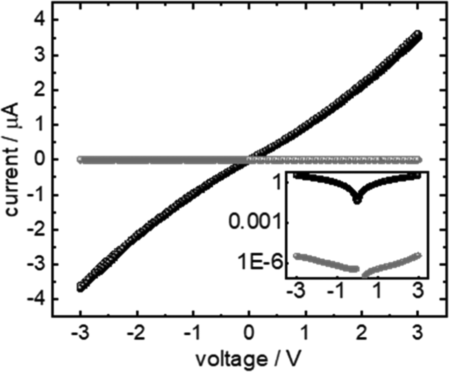 | ||
| Fig. 7 Conductivity of polyMP@3. The current–voltage curve of the polyMP@3 sample is shown in black, and the current–voltage curve of 3 is shown as a reference in grey. The inset shows the data on a logarithmic scale. | ||
Conclusions
We have successfully carried out Pd-catalysed polymerization of methyl propiolate in the pores of three different SURMOFs: SURMOF-2, Cu2(bdc)2(dabco) and HKUST-1. We investigated the influence of pore volumes and pore channels on polymerization, yielding interesting results: the maximum chain length of bulk polymers determined from MALDI-ToF was n = 23, which we obtained for the 3D pore system of HKUST-1, whereas we obtained n = 22 and n = 19 for SURMOF-2 and Cu2(bdc)2(dabco), respectively. In SEM and EDXM analyses, we observed surface-covering top-layer formation for systems SURMOF-2 and Cu2(bdc)2(dabco), whereas a perfect polymerization reaction is observed for HKUST-1. We investigated the desorption kinetics by QCM experiments and observed quick desorption from HKUST-1, whereas depot-like slow and steady desorption was observed for SURMOF-2, which we assume to be the cause for the top-layer formation in the latter case. From AFM analysis, comparing the bulk polymer to the polymer formed inside HKUST-1, we observe clear control over polymerization: the polymer in the MOF pores forms fibers and tiny particle agglomerates, whereas bulk polymerization yields large spherical particles. Using SIMS analysis we find that, despite the top-layer formation, in all cases polymerization occurs inside the pore systems, which was also highlighted by depth profiling and depth integrated spectra. Finally, for the best working 3D system of HKUST-1, we measured the increase of electrical conductivity after polymerization, which appeared to be 6 orders of magnitude higher than that of the empty HKUST-1. An increase in the electrical conductivity of the MOF system plays a crucial and important role in the potential electrical applications of MOFs, e.g. in sensors or microelectronics, where the insulating, porous structure of the MOF and an electronically conductive electrolyte are needed, such as in supercapacitors. In summary, we introduced lots of novel characterization methods and interpretations of the same, leading towards the prediction of polymerization reactions inside the frameworks of SURMOFs that could further help in developing devices. Introducing electrical conductivity to SURMOFs is of key importance as it leads to various possible applications, such as pseudocapacitors, sensors and actuators.Conflicts of interest
There are no conflicts to declare.Acknowledgements
B. S., C. B.-K. and C. W. are thankful for funding through the German Science Foundation (DFG) within the special research field of the SFB 1176 on project C4. A. K. and C. W. are thankful for funding through the German Science Foundation (DFG) within the special research field of the SFB 1176 on project C6. We thank Dr Alexander Welle for the SIMS measurements and acknowledge that the SIMS studies were performed at the Karlsruhe Nano Micro Facility (KNMF). C.B.-K. acknowledges the Australian Research Council (ARC) for funding in the context of a Laureate Fellowship.Notes and references
- B. V. K. J. Schmidt, Macromol. Rapid Commun., 2020, 41, 1900333 CrossRef CAS.
- U. S. F. Arrozi, V. Bon, C. Kutzscher, I. Senkovska and S. Kaskel, Dalton Trans., 2019, 48, 3415–3421 RSC.
- M. Rivera-Torrente, P. D. Pletcher, M. K. Jongkind, N. Nikolopoulos and B. M. Weckhuysen, ACS Catal., 2019, 9, 3059–3069 CrossRef CAS.
- S. Kitagawa, R. Kitaura and S. Noro, Angew. Chem., Int. Ed., 2004, 43, 2334–2375 CrossRef CAS.
- O. M. Yaghi, M. O'Keeffe, N. W. Ockwig, H. K. Chae, M. Eddaoudi and J. Kim, Nature, 2003, 423, 705–714 CrossRef CAS.
- S. L. James, Chem. Soc. Rev., 2003, 32, 276–288 RSC.
- J. R. Long and O. M. Yaghi, Chem. Soc. Rev., 2009, 38, 1213–1214 RSC.
- S. M. Cohen, Chem. Rev., 2012, 112, 970–1000 CrossRef CAS.
- H. Deng, S. Grunder, K. E. Cordova, C. Valente, H. Furukawa, M. Hmadeh, F. Gándara, A. C. Whalley, Z. Liu, S. Asahina, H. Kazumori, M. O'Keeffe, O. Terasaki, J. F. Stoddart and O. M. Yaghi, Science, 2012, 336, 1018–1023 CrossRef CAS.
- G. Skorupskii, B. A. Trump, T. W. Kasel, C. M. Brown, C. H. Hendon and M. Dincă, Nat. Chem., 2020, 12, 131–136 CrossRef CAS.
- R. Dong, Z. Zhang, D. C. Tranca, S. Zhou, M. Wang, P. Adler, Z. Liao, F. Liu, Y. Sun, W. Shi, Z. Zhang, E. Zschech, S. C. B. Mannsfeld, C. Felser and X. Feng, Nat. Commun., 2018, 9, 2637 CrossRef.
- D. Sheberla, L. Sun, M. A. Blood-Forsythe, S. Er, C. R. Wade, C. K. Brozek, A. Aspuru-Guzik and M. Dincă, J. Am. Chem. Soc., 2014, 136, 8859–8862 CrossRef CAS.
- J. Lee, O. K. Farha, J. Roberts, K. A. Scheidt, S. T. Nguyen and J. T. Hupp, Chem. Soc. Rev., 2009, 38, 1450–1459 RSC.
- Z. Kang, L. Fan and D. Sun, J. Mater. Chem. A, 2017, 5, 10073–10091 RSC.
- Z. R. Herm, E. D. Bloch and J. R. Long, Chem. Mater., 2014, 26, 323–338 CrossRef CAS.
- R. Ricco, K. Konstas, M. J. Styles, J. J. Richardson, R. Babarao, K. Suzuki, P. Scopece and P. Falcaro, J. Mater. Chem. A, 2015, 3, 19822–19831 RSC.
- H. C. Zhou, J. R. Long and O. M. Yaghi, Chem. Rev., 2012, 112, 673–674 CrossRef CAS.
- K. K. Tanabe and S. M. Cohen, Chem. Soc. Rev., 2011, 40, 498–519 RSC.
- D. J. Tranchemontagne, J. L. Mendoza-Cortes, M. O'Keeffe and O. M. Yaghi, Chem. Soc. Rev., 2009, 38, 1257–1283 RSC.
- Z. Q. Wang and S. M. Cohen, Chem. Soc. Rev., 2009, 38, 1315–1329 RSC.
- H.-C. Lee, J. Hwang, U. Schilde, M. Antonietti, K. Matyjaszewski and B. V. K. J. Schmidt, Chem. Mater., 2018, 30, 2983–2994 CrossRef CAS.
- N. Ding, H. Li, X. Feng, Q. Wang, S. Wang, L. Ma, J. Zhou and B. Wang, J. Am. Chem. Soc., 2016, 138, 10100–10103 CrossRef CAS.
- T. Uemura, Y. Ono, K. Kitagawa and S. Kitagawa, Macromolecules, 2008, 41, 87–94 CrossRef CAS.
- T. Uemura, Y. Ono and S. Kitagawa, Chem. Lett., 2008, 37, 616–617 CrossRef CAS.
- T. Uemura, R. Kitaura, Y. Ohta, M. Nagaoka and S. Kitagawa, Angew. Chem., Int. Ed., 2006, 45, 4112–4116 CrossRef CAS.
- T. Kitao, M. W. A. MacLean, K. Nakata, M. Takayanagi, M. Nagaoka and T. Uemura, J. Am. Chem. Soc., 2020, 142, 5509–5514 CrossRef CAS.
- X. Zhang, T. Kitao, D. Piga, R. Hongu, S. Bracco, A. Comotti, P. Sozzani and T. Uemura, Chem. Sci., 2020, 11, 10844–10849 RSC.
- T. Uemura, N. Yanai and S. Kitagawa, Chem. Soc. Rev., 2009, 38, 1228–1236 RSC.
- T. Uemura, D. Hiramatsu, Y. Kubota, M. Takata and S. Kitagawa, Angew. Chem., Int. Ed., 2007, 46, 4987–4990 CrossRef CAS.
- T. Uemura, T. Kaseda and S. Kitagawa, Chem. Mater., 2013, 25, 3772–3776 CrossRef CAS.
- T. S. Wang, M. Farajollahi, S. Henke, T. T. Zhu, S. R. Bajpe, S. J. Sun, J. S. Barnard, J. S. Lee, J. D. W. Madden, A. K. Cheetham and S. K. Smoukov, Mater. Horiz., 2017, 4, 64–71 RSC.
- C. J. Lu, T. Ben, S. X. Xu and S. L. Qiu, Angew. Chem., Int. Ed., 2014, 53, 6454–6458 CrossRef CAS.
- H. Gliemann and C. Woll, Mater. Today, 2012, 15, 110–116 CrossRef CAS.
- R. Haldar, B. Sen, S. Hurrle, T. Kitao, R. Sankhla, B. Kühl, A. Welle, S. Heissler, G. Brenner-Weiß, P. Thissen, T. Uemura, H. Gliemann, C. Barner-Kowollik and C. Wöll, Eur. Polym. J., 2018, 109, 162–168 CrossRef CAS.
- Z.-G. Gu, W.-Q. Fu, M. Liu and J. Zhang, Chem. Commun., 2017, 53, 1470–1473 RSC.
- B. Liu, O. Shekhah, H. K. Arslan, J. X. Liu, C. Woll and R. A. Fischer, Angew. Chem., Int. Ed., 2012, 51, 807–810 CrossRef CAS.
- A. Betard and R. A. Fischer, Chem. Rev., 2012, 112, 1055–1083 CrossRef CAS.
- J. X. Liu and C. Woll, Chem. Soc. Rev., 2017, 46, 5730–5770 RSC.
- O. Shekhah, J. Liu, R. A. Fischer and C. Woll, Chem. Soc. Rev., 2011, 40, 1081–1106 RSC.
- B. Liu and R. A. Fischer, Sci. China: Chem., 2011, 54, 1851–1866 CrossRef CAS.
- K. Vanommeslaeghe and A. D. MacKerell Jr., J. Chem. Inf. Model., 2012, 52, 3144–3154 CrossRef CAS.
- K. Vanommeslaeghe, E. P. Raman and A. D. MacKerell Jr., J. Chem. Inf. Model., 2012, 52, 3155–3168 CrossRef CAS.
- W. Yu, X. He, K. Vanommeslaeghe and A. D. MacKerell Jr., J. Comput. Chem., 2012, 33, 2451–2468 CrossRef CAS.
- I. Soteras Gutiérrez, F. Y. Lin, K. Vanommeslaeghe, J. A. Lemkul, K. A. Armacost, C. L. Brooks 3rd and A. D. MacKerell Jr., Bioorg. Med. Chem., 2016, 24, 4812–4825 CrossRef.
- Z. Wang, A. Błaszczyk, O. Fuhr, S. Heissler, C. Wöll and M. Mayor, Nat. Commun., 2017, 8, 14442 CrossRef CAS.
- S. Garg, H. Schwartz, M. Kozlowska, A. B. Kanj, K. Müller, W. Wenzel, U. Ruschewitz and L. Heinke, Angew. Chem., Int. Ed., 2019, 58, 1193–1197 CrossRef CAS.
- O. Shekhah, H. Wang, S. Kowarik, F. Schreiber, M. Paulus, M. Tolan, C. Sternemann, F. Evers, D. Zacher, R. A. Fischer and C. Wöll, J. Am. Chem. Soc., 2007, 129, 15118–15119 CrossRef CAS.
- M. Kind and C. Wöll, Prog. Surf. Sci., 2009, 84, 230–278 CrossRef CAS.
- H. K. Arslan, O. Shekhah, D. C. F. Wieland, M. Paulus, C. Sternemann, M. A. Schroer, S. Tiemeyer, M. Tolan, R. A. Fischer and C. Wöll, J. Am. Chem. Soc., 2011, 133, 8158–8161 CrossRef CAS.
- C. I. Simionescu, V. Bulacovschi, M. Grovu-ivanoiu and A. Stanciu, J. Macromol. Sci., Part A, 1987, 24, 611–622 CrossRef.
- J. X. Liu, B. Lukose, O. Shekhah, H. K. Arslan, P. Weidler, H. Gliemann, S. Brase, S. Grosjean, A. Godt, X. L. Feng, K. Mullen, I. B. Magdau, T. Heine and C. Woll, Sci. Rep., 2012, 2, 5 Search PubMed.
- M. Maes, S. Schouteden, K. Hirai, S. Furukawa, S. Kitagawa and D. E. De Vos, Langmuir, 2011, 27, 9083–9087 CrossRef CAS.
- S. D. Worrall, M. A. Bissett, P. I. Hill, A. P. Rooney, S. J. Haigh, M. P. Attfield and R. A. W. Dryfe, Electrochim. Acta, 2016, 222, 361–369 CrossRef CAS.
- J. Liu, T. Wächter, A. Irmler, P. G. Weidler, H. Gliemann, F. Pauly, V. Mugnaini, M. Zharnikov and C. Wöll, ACS Appl. Mater. Interfaces, 2015, 7, 9824–9830 CrossRef CAS.
- A. B. Kanj, R. Verma, M. Liu, J. Helfferich, W. Wenzel and L. Heinke, Nano Lett., 2019, 19, 2114–2120 CrossRef CAS.
- A. A. Talin, A. Centrone, A. C. Ford, M. E. Foster, V. Stavila, P. Haney, R. A. Kinney, V. Szalai, F. El Gabaly, H. P. Yoon, F. Léonard and M. D. Allendorf, Science, 2014, 343, 66–69 CrossRef CAS.
- A. Knebel, B. Geppert, K. Volgmann, D. I. Kolokolov, A. G. Stepanov, J. Twiefel, P. Heitjans, D. Volkmer and J. Caro, Science, 2017, 358, 347–351 CrossRef CAS.
Footnote |
| † Electronic supplementary information (ESI) available. See DOI: 10.1039/d0nr06848a |
| This journal is © The Royal Society of Chemistry 2020 |