
Removal of residual contaminants by minute-level washing facilitates the direct regeneration of spent cathodes from retired EV Li-ion batteries†
Yi
Guo‡
a,
Yang
Li‡
bcd,
Kai
Qiu
d,
Yan
Li
e,
Weijing
Yuan
b,
Chenxi
Li
b,
Xinyu
Rui
a,
Lewei
Shi
b,
Yukun
Hou
a,
Saiyue
Liu
a,
Dongsheng
Ren
*a,
Tiening
Tan
*d,
Gaolong
Zhu
d,
Languang
Lu
a,
Shengming
Xu
 f,
Biao
Deng
g,
Xiang
Liu
*b and
Minggao
Ouyang
*a
f,
Biao
Deng
g,
Xiang
Liu
*b and
Minggao
Ouyang
*a
aSchool of Vehicle and Mobility, Tsinghua University, Beijing 100084, P. R. China. E-mail: ouymg@tsinghua.edu.cn
bSchool of Material Science and Engineering, Beihang University, Beijing 100191, P. R. China. E-mail: xiangliu@buaa.edu.cn
cSchool of Transportation Science and Engineering, Beihang University, Beijing, 100191, P. R. China
dProf. Ouyang Minggao Academician Workstation, Sichuan New Energy Vehicle innovation Center Co., Ltd., Sichuan, 644000, P. R. China. E-mail: tiening.tan@sevc.com.cn
eBeijing Key Laboratory of Microstructure and Properties of Solids, Faculty of Materials and Manufacturing, Beijing University of Technology, Beijing 100124, P. R. China
fInstitute of Nuclear and New Energy Technology, Tsinghua University, Beijing 100084, P. R. China
gShanghai Institute of Applied Physics, Chinese Academy of Sciences, Shanghai 201204, P. R. China
First published on 7th November 2024
Abstract
The direct regeneration of spent cathodes stands out as an environmentally and economically benign strategy within the battery ecosystem, eclipsing the cumbersome metallurgical approaches. Before addressing the lithium loss and structural degradation, it is crucial to focus on the residual contaminants within the spent cathode collected from retired Li-ion batteries after industrial exfoliation processes. Here, comprehensive characterizations and calculations show that in contrast to metal scraps, the electrolyte decomposition after battery operation and heating exfoliation uniformly coat the particle surfaces of cathodes, severely impeding the reuse and rejuvenation of LiNixCoyMnzO2 (NCM) cathodes with limited degradation by obstructing lithium diffusion. Considering the high costs and environmental risks of organic systems, we further propose a minute-level water-based pretreatment to purify the spent cathode and selectively eliminate these stubborn impurities that can deteriorate the interfacial chemical state, even after prolonged high-temperature heat treatment. Combined with a solid-state regeneration process, a purified 250k-miles-serviced (8 year) cathode could be rejuvenated to match the pristine one's capacity and cycling retention, displaying a 1.9-fold increase in average lithium diffusivity for charging and 43% enhanced capacity retention after 200 cycles compared with the unpurified one. Our study underscores the critical role of previously overlooked chemical residuals in facilitating the practical direct regeneration of retired lithium-ion batteries.
Broader contextCurrently, conventional pyro-/hydro-metallurgy recycling technology encounters challenges in meeting the demands for cost-effectiveness, efficiency, and environmental sustainability. Therefore, the direct recycling strategy has captured the attention of the global scientific community and many enterprises. For degraded cathode black mass, researchers predominantly focus on the compositional and structural defects but tend to overlook chemical obstacles arising from the prolonged cycling of used batteries, especially for EV batteries that have endured decades of operation exceeding 250![[thin space (1/6-em)]](https://www.rsc.org/images/entities/char_2009.gif) 000 miles. These impurities prevent Li+ from inserting into the damaged layered structure during reuse or direct regeneration. Our findings propose an effective strategy for eliminating chemical defects and revitalizing degraded cathodes into high-performance regenerated ones. This study underscores a significant yet frequently disregarded impediment that obstructs the direct regeneration and upcycling of the rising tide of retired Li-ion batteries. 000 miles. These impurities prevent Li+ from inserting into the damaged layered structure during reuse or direct regeneration. Our findings propose an effective strategy for eliminating chemical defects and revitalizing degraded cathodes into high-performance regenerated ones. This study underscores a significant yet frequently disregarded impediment that obstructs the direct regeneration and upcycling of the rising tide of retired Li-ion batteries.
|
Introduction
Lithium-ion batteries (LIBs) significantly contribute to establishing low-carbon energy systems, powering electric vehicles (EVs) and energy-storage solutions.1,2 Fueled by environmental policies, the global demand for LIBs in EVs and energy storage is estimated to increase six-fold to 2.2 TWh and fifteen-fold to 1194 GWh between 2021 and 2030.3,4 Nevertheless, the surging demand inevitably reduces the supply resilience of the critical raw minerals, particularly lithium and cobalt.5,6 Overexploitation of the high-grade ores and processing of the low-grade ores could result in significant ecological vulnerabilities and public health issues.7,8 When spent LIBs are dumped into the environment, toxic components inside the LIBs also pose environmental and health risks.9 Hence, there is a pressing need for sustainable and closed-loop utilization of spent LIBs.Unlike the traditional pyro-/hydro-metallurgy processes, direct recycling focuses on reusing valuable components from spent LIBs after rejuvenation, and therefore can reduce greenhouse gas (GHG) emissions and chemical consumption.10,11 Previous studies based on small-scale lab-level processes have presented the feasibility of direct regeneration.12–16 Cheng focused on lithium loss within recycled cathodes and employed a Li-rich molten environment to replenish lithium.12,14 It has been proven that through the rejuvenation process, cathode structural degradation, including cracks, degraded microphases and cation mixing, can be sufficiently erased and the cathode can be transformed into a reusable cathode.13,15 In brief, these compositional and structural defects, including lithium loss, cracks, and degraded phases, are identified as noteworthy hurdles in the recovery of the electrochemical performances for degraded cathodes.
However, spent batteries destined for recycling have endured thousands of charge/discharge cycles over decades and are typically separated and shredded to form the so-called black mass before further purification (Table S1 of ESI†). The black mass is convenient and safe for transportation compared with the whole batteries, which may suffer from thermal runaway, and thus the black mass serves as the most common intermediate form in the battery recycling supply chain.17,18 During the back mass harvesting procedure, contamination within the black mass may exist (e.g., electrolyte side-reaction residuals,19 current collector fragments20), which may influence the following direct regeneration process. In contrast, many reported lab-scale studies on cathode regeneration were based on cathodes manually extracted from hundred-cycle pouch cells or coin-cells and subsequently rinsed with organic solvents, such as dimethyl carbonate (DMC) and 1-methyl-2-pyrrolidinone (NMP) (Table S2, ESI†),21 and despite their effectiveness in cleaning off electrolyte residuals and delamination, the use of organic solvents is not suitable for large-scale processing due to environmental issues and cost-effectiveness considerations.22–25 Therefore, there is an urgent need to prioritize the regeneration of real black mass from long-term serviced lithium-ion batteries from EVs without pretreatment using an organic solvent.
In this study, recycled NCM black mass was collected from end-of-life EVs driven over 250000 miles for more than 8 years’ service. Based on a series of metal purifications (Fig. S1 of the ESI†), most spent cathodes undergo direct regeneration. Through in situ and ex situ characterizations, and theoretical calculations, it was revealed that the trace amounts of impurities accumulated during the electrochemical cycling and heat pretreatment on the cathode surface can significantly hinder the rejuvenation process of industrial-level spent cathodes by impeding lithium transportation. Furthermore, a minute-level pretreatment method was proposed for fully restoring the chemical composition, crystal structure, and electrochemical performance of the used cathode material.
Results and discussion
Neglected chemical residual on 250k-miles-serviced cathodes
As shown in the Materials and methods and Fig. S1 (ESI†), a series of pretreatments, such as sorting, dismantling, crushing, and shredding, were employed to collect the spent NCM cathode (denoted as S-NCM) with minor metal and polyvinylidene fluoride (PVDF) binder (Table S3 and Fig. S2, ESI†). First, a comprehensive comparison between S-NCM and pristine NCM cathodes (P-NCM) was conducted to identify the failure mechanism of the S-NCM materials. As shown in scanning electron microscope (SEM) images (Fig. 1a and Fig. S3, ESI†), the end-of-life battery S-NCM cathode showed intensive rough surface residuals with minor cracks after 250000-mile service, with the planar gliding degradation and cracks in the single-crystal cathode consistent with previous reports.26,27 The X-ray diffraction (XRD) analysis, shown in Fig. 1b, demonstrated that the S-NCM still preserved an ordered layered R![[3 with combining macron]](https://www.rsc.org/images/entities/char_0033_0304.gif) m structure with a minor degraded phase near the (101), (104), and (018) peaks, possibly corresponding to the subtle monoclinic phase transition due to lithium loss.28 According to the high angle annular dark field scanning transmission electron microscopy (HAADF-STEM) analysis and fast Fourier transform (FFT) pattern (Fig. 1c and Fig. S4, ESI†), the degraded S-NCM cathode showed a spinel phase in zone 2 and exhibited significant spatial heterogeneity. Besides the structural degradation, the inductively coupled plasma optical emission spectrometry (ICP-OES) result (Fig. 1d and Table S4, ESI†) indicated that, even after the long-term cycling, the end-of-life S-NCM cathode showed only 13.1% loss of Li inventory compared to the pristine P-NCM. Contradictorily, the specific capacity of S-NCM significantly declined to 37.5 mA h g−1 compared to 178.1 mA h g−1 for the P-NCM, as shown in Fig. 1d. Especially in the follow-up cycle, see Fig. S5 (ESI†), the S-NCM cathode exhibited a capacity of less than 10 mA h g−1 after 100 cycles. Note that, there was only 13.1% Li deficiencies, which could not sufficiently account for the 78.9% capacity fading of S-NCM. Therefore, to further reveal the origin of the poor electrochemical performance, electrochemical impedance spectroscopy (EIS) characterization was conducted, as shown in Fig. 1d and Fig. S6 (ESI†), the charge-transfer resistance (Rct) for S-NCM steeply climbed to 2105 Ω and was four times larger than the P-NCM of 500 Ω. The increased impedance deteriorates the Li+ diffusion, thus leading to the critical capacity decay. Therefore, the surface state of the spent cathode was recognized as the key issue limiting its capacity delivery, compared to compositional lithium loss and structural bulk defects.
m structure with a minor degraded phase near the (101), (104), and (018) peaks, possibly corresponding to the subtle monoclinic phase transition due to lithium loss.28 According to the high angle annular dark field scanning transmission electron microscopy (HAADF-STEM) analysis and fast Fourier transform (FFT) pattern (Fig. 1c and Fig. S4, ESI†), the degraded S-NCM cathode showed a spinel phase in zone 2 and exhibited significant spatial heterogeneity. Besides the structural degradation, the inductively coupled plasma optical emission spectrometry (ICP-OES) result (Fig. 1d and Table S4, ESI†) indicated that, even after the long-term cycling, the end-of-life S-NCM cathode showed only 13.1% loss of Li inventory compared to the pristine P-NCM. Contradictorily, the specific capacity of S-NCM significantly declined to 37.5 mA h g−1 compared to 178.1 mA h g−1 for the P-NCM, as shown in Fig. 1d. Especially in the follow-up cycle, see Fig. S5 (ESI†), the S-NCM cathode exhibited a capacity of less than 10 mA h g−1 after 100 cycles. Note that, there was only 13.1% Li deficiencies, which could not sufficiently account for the 78.9% capacity fading of S-NCM. Therefore, to further reveal the origin of the poor electrochemical performance, electrochemical impedance spectroscopy (EIS) characterization was conducted, as shown in Fig. 1d and Fig. S6 (ESI†), the charge-transfer resistance (Rct) for S-NCM steeply climbed to 2105 Ω and was four times larger than the P-NCM of 500 Ω. The increased impedance deteriorates the Li+ diffusion, thus leading to the critical capacity decay. Therefore, the surface state of the spent cathode was recognized as the key issue limiting its capacity delivery, compared to compositional lithium loss and structural bulk defects.
 | ||
| Fig. 1 Neglected chemical residuals on the 250k-miles-serviced cathode. (a) SEM image and (b) XRD pattern of the degraded S-NCM. The black dotted circle accentuates the subtle peaks that do not belong to the layered structure; (c) high-resolution HAADF-STEM images on the central area of the S-NCM particle and the FFT patterns of the selected dark and bright regions; (d) comprehensive comparison of lithium loss in degraded powders measured by ICP-OES, electrochemical capacity, and charge-transfer resistance analyses in the half-cell using S-NCM and P-NCM powders as cathode active materials; (e) F 1s XPS patterns of S-NCM powders for different sputtering times using an ion-beam. Based on the calculated integral area, the proportional values of the organics and inorganics in fluoride are presented in the patterns; (f) HAADF-STEM images based on focused ion beam cutting and an enlarged view displaying the interior microcracks. Corresponding EDS mapping analysis indicates the presence of F elements along these microcracks pointed out by a white arrow. (g) Deficiencies of S-NCM addressed before direct regeneration, including the compositional and structural aspects (e.g., irreversible lithium-ionic loss, phase degradation, internal and external cracks) and latent chemical defects (e.g., surface and crack-edge impurities enriching the F element). | ||
To understand the surface state of the spent cathode, energy-dispersive spectroscopy (EDS) element mapping and X-ray photoelectron spectroscopy (XPS) were conducted. As shown in Fig. S7–S9, and Tables S5, S6 (ESI†), the S-NCM cathode surface residuals consisted of C, O, F, and P elements, and displayed a surface-rich gradient distribution, as revealed by XPS with etching. The F 1s XPS peaks with etching for S-NCM are shown in Fig. 1e, where two F 1s peaks could be observed before sputtering, with the major peak centered at 685.5 eV, which was attributed to inorganic fluorides and the minor F 1s peak centered at 690.4 eV, which could be assigned to organic fluorides, with the ratio of 53.8% for organic flourides.29 However, the organic-related F peak declined significantly after sputtering, and completely disappeared after 300 s Ar+ sputtering. The surface-rich distribution of organic fluoride was consistent with the cathode electrolyte interphase (CEI) composition previously reported.29,30
To further reveal the microscopic distribution of those F-rich residuals, SEM combined with time-of-flight secondary ion mass spectrometry (SEM-ToF-SIMS) characterization was conducted for the cycled cathode. The results are shown in Fig. S10 and Videos S1, S2 (ESI†). Based on the spatial distribution of F− secondary ion fragments, it was confirmed that fluoride impurities were primarily deposited on the particle surface. Moreover, during the long-time battery service, it could be observed from the HAADF-STEM image and corresponding element mapping (see Fig. 1f) that, in the S-NCM cathode, the fluorides could spread into the interior of the cathode along the intragranular cracks. Coincidentally, from the selected FFT figure shown in Fig. S4 (ESI†), the existence of an amorphous ring was observed along the intragranular cracking, which may be related to the fluorides also observed in the bulk. To sum up, the collected S-NCM exhibited limited structural and compositional degradation, while preserving the fluoride-containing impurities aggregated on the surface and along the intragranular cracks, as illustrated in Fig. 1g.
Furthermore, it was previously widely accepted that the source of F-rich impurities in the spent cathode was due to decomposition of the PVDF binder during the heat delamination process at around 350 °C;11,23–25,31 however, during the thermal decomposition of PVDF, most the fluoride-containing products were gas species (i.e., HF) and fragments (–CF– and –CH–CF–),32–34 which are subject to ejection instead of propagating along the cathode intragranular cracks. To confirm the source of those observed residual impurities, four kinds of cathodes with varying cycling conditions were collected and examined, namely cathode laminates with/without electrolyte filling, and laminates from 125k and 250k miles-serviced batteries, as listed in Table S7 (ESI†). The SEM images and electrochemical performance are shown in Fig. S11 and S12 (ESI†). Compared with the pristine one (sample A), the other spent cathodes from battery formation and cycling exhibited a rough surface and limited discharge capacity. Notably, the laminate from formation only but with no cycling (sample B), which it was believed would retain the full lithium inventory and show negligible structural degradation since it had not undergone charge/discharge cycling, showed a poor discharge capacity, which was the same as the other long-cycled ones. Moreover, the heat exfoliation used to pyrolyze the adhesive binders deteriorated the original CEI layer on the spent cathodes and generated more harmful byproducts (e.g., Li2CO3, Li3PO4, LiF). This, combined with electrolyte decomposition during electrochemical cycling, exacerbates chemical degradation, resulting in a significant capacity decline. Therefore, the above comparison revealed that the cathode residual impurities should originate from the electrolyte components (such as LiPF6, DMC, ethylene carbonate (EC)) decomposition during battery formation, cycling, and common heat exfoliation, leading to severe capacity loss in spent cathodes (Fig. 1d).
Purifying the residuals to promote direct regeneration
In contrast to aluminum and copper metallic fragments contacted with cathodes through a pyrolyzable binder, the cathode electrolyte residuals covered the surface and penetrated along the microcracks and could not be separated by a physical method. Moreover, the inorganic residual component could not be burned out due to its high decomposition temperature, such as LiF. Therefore, the impact and role of the residual impurity elements in the following regeneration process were investigated. As illustrated in Fig. 2a, inspired by the high solubility of F-rich compounds in acid solution,35,36 a homogeneous minute-level acid solution pretreatment was developed prior to the high-temperature regeneration sintering. Moreover, the purifying acid solution can disperse on the cathode surface and along the microcracks, and therefore can effectively erase the residuals. XPS characterization was conducted to confirm the effect of the pretreatment, as shown in Fig. 2b, where the F 1s peak was found to decrease significantly with the acid concentration above 1 M, indicating the effectiveness of this pretreatment. Moreover, compositional analyses (Fig. S8, S13 and Tables S4–S6 and S8, ESI†) indicated that the ratio of the transition metal elements of S-NCM after cleaning in 1 M HNO3 solution (C-NCM) remained unchanged and the P and F elemental contents of C-NCM decreased to levels close to that of P-NCM. In the Fourier Transform infrared (FTIR) spectrum (Fig. S14, ESI†), the C-NCM showed no characteristic peak for the covalent C–F bond at 1060 cm−1 compared to P-NCM and S-NCM, and nor did it display peaks attributed to the residual alkali Li2CO3 at ∼1423 and ∼877 cm−1.37,38 The SEM-ToF-SIMS spatial distribution of the F element (Fig. S15 and Videos S3, S4, ESI†) for the C-NCM cathode confirmed no obvious F element could be observed after the cleaning pretreatment. In addition, based on the EIS measurements of C-NCM and S-NCM (Fig. S16, ESI†), the contact resistance of C-NCM was decreased by three times that of the S-NCM. This further implied that the residual cathode impurities may act as a barrier that impede Li-ion transition. Furthermore, the morphological and structural characteristics of the recycled cathode were also investigated after the purifying treatment, as shown in Fig. 2c and Fig. S17 (ESI†). It was noted that the C-NCM cathode still maintained its morphology and integrity of the layered structure with limited monoclinic phase transition,28 as evidenced by the XRD patterns (Fig. S17 and S18, ESI†). Based on element analysis of the washing acid filtrate (Table S9, ESI†) and two-dimensional full-field transmission X-ray microscopy with X-ray absorption near-edge structure spectroscopy (2D TXM-XANES) (Fig. S19, ESI†) analyses for the cleaned cathodes particles, it was found that the acid washing treatment could, to a limited degree, dissolve the degraded surface and expose the bulk phase of the spent cathodes with a layered characteristic.39 Although, it was previously accepted that the Ni-rich cathode is sensitive to humid and acid environments, we confirmed that the acid pretreatment developed here did not cause bulk damage to the cathode. As shown in Fig. S20, S21 and Table S10 (ESI†), we conducted additional cleaning experiments using a fresh Ni83 single-crystal cathode, which is known for its high sensitivity to the environment. Despite an increase in leaching concentrations up to 3 M, the chemical composition and micro-morphology of the cathode remained unchanged, which may be related to the Li+/H+ exchange mechanism with the stabilizing lattice structure.40,41 Moreover, as shown in Fig. 2b and Fig. S22 (ESI†), based on the charge/discharge efficiency, we further optimized the solution concentration as 1 M in the following investigations. | ||
| Fig. 2 Removal of the impurities and change in the crystal structure during the direct regeneration process combined with pretreatment. (a) Traditional direct regeneration path using solid-state sintering and the minute-level pretreatment introduced in an advanced path targeted to the critical obstacles within degraded cathode materials; (b) F 1s XPS fine patterns of C-NCM undergoing ultrasonic stirring in solutions with different concentrations; (c) SEM image of C-NCM obtained by soaking S-NCM in 1 M HNO3 solution; (d) partial in situ XRD patterns of S-NCM and C-NCM mixed with a Li resource, keeping a constant heating rate (20 °C min−1) and holding the temperature for diffraction at 50 °C intervals; (e) evolution of the unit cell parameters a and c for S-NCM (blue symbols) and C-NCM (red symbols) mixed with Li slate through Rietveld refinement. The earlier Li+ insertion at 200 °C changed the variation tendency of the unit parameters for the sample after cleaning. (f) Heat generation measured by DSC from mixtures. | ||
To reveal the effect of the residuals during the direct regeneration of the recycled cathode, in situ XRD characterizations were compared following the regeneration of S-NCM and C-NCM. During the heating, the unit cell lattice first nearly linearly expanded until there was a differentiation of the expansion ratio caused by the lithium insertion. As shown in Fig. 2d, the shift of the (003) peak of C-NCM was less pronounced than that of S-NCM when heating to 900 °C, indicating its unit cell lattice c was not expanded as much as for the S-NCM due to its more efficient lithium insertion. Therefore, more lithium insertion was observed for the C-NCM cathode. Correspondingly, the Li2CO3 in the mixture of S-NCM and C-NCM also performed differently, whereby the Li2CO3 in the C-NCM cathode was consumed gradually until it disappeared at its melting point around 730 °C, while the Li2CO3 in the S-NCM cathode completely vanished at around only 600 °C, and this earlier consumption of the lithium source may be attributed to the reaction between Li2CO3 and the residual impurities (such as LiF, LiOH, and Li3PO4) by co-melting, vaporizing, and replenishing in S-NCM.42 Equivalently, the high angle reflection peak intensity spanning from (006) to (110), representing the layered structure, significantly increased starting from around 200 °C for the C-NCM cathode after the purifying treatment compared to there being no obvious enhancement for S-NCM, indicting the better repair of the layered structure during heating. To further unveil the underlying mechanism, Rietveld refinement of each XRD pattern was conducted, which can depict the continuous change of the unit cell parameters during regeneration. Generally, the unit cell parameter c decreases and a increases with the insertion of Li ions into a layered structure, similar to in the discharge process.28 As shown in Fig. 2e, the lattice evolution of the S- and C-NCM cathodes were compared. For C-NCM, the lattice c expansion slope became obviously flatter at 200 °C, denoting a lattice c shrinkage at this temperature induced by the Li-ion insertion and repairing. However, for the S-NCM without undergoing purifying treatment for the residuals, the lattice expanded still nearly linearly with no obvious lithium insertion until 600 °C. Concurrently, the lattice a expansion slope became steeper at 200 °C for C-NCM. Last but not least, Differential scanning calorimetry (DSC) characterization was also conducted during the regeneration process to confirm the lithium insertion pattern for the S- and C-NCM cathodes, which can trace the lithium replenishment associated with the exothermic reaction as reported by others.43 As shown in Fig. 2f, the characteristic exothermic reaction at around 200 °C was only observed for C-NCM, confirmed the earlier lithium insertion after the purifying treatment. The earlier lithium insertion was also supported by the CO2 gas release observed during Li2CO3 decomposition to supply the lithium source for the C-NCM cathode, as shown Fig. S23 (ESI†). Moreover, from the thermogravimetric results shown in Fig. 2f, the weight loss of C-NCM was 5.4%, which was significantly larger than that of S-NCM of 2.5%, indicating that more Li2CO3 was activated and decomposed to provide the lithium source for C-NCM.43,44 To sum up, through multiple in situ and ex situ characterizations, we proved that, with a purifying pretreatment, the direct regeneration could be facilitated to start at a lower temperature of 200 °C from the spent cathode.
Impact of impurities on the electrochemical performance of the regenerated NCM cathodes
Given the importance of the residual impurity during the regeneration process, it was crucial to further scrutinize the chemical, structural, and electrochemical properties of the regenerated S- and C-NCM cathodes. Here, the S-NCM and C-NCM cathodes were directly repaired, forming the R-S-NCM and R-C-NCM cathodes, with all the steps identical except for the purifying pretreatment for R-C-NCM (Fig. 2a). At first, as shown in Fig. S24 (ESI†), the PVDF binder and Super P within the spent cathode could completely decompose in air with an O2 atmosphere at 550 °C and 750 °C, which suggested these additives led to only minor residuals for the regenerated cathode after the high-temperature regeneration. Comparing the morphology (Fig. S25, ESI†) and element composition (Table S4, ESI†) showed that both the regenerated cathodes exhibited a smooth surface without cracks and possessed a similar composition as pristine P-NCM. However, the element distribution was distinct, as indicated by the corresponding EDS mapping shown in Fig. 3a and b, where it could be clearly seen that there were fluorine residuals aggregated in the nanopores inside the R-S-NCM cathode, while the R-C-NCM cathode did not show a F-rich area. Meanwhile, the XPS (Fig. 3c and Fig. S26, ESI†) results showed that the R-C-NCM cathode exhibited a much less intense F 1s characteristic peak and more similar C 1s and O 2p peaks with the P-NCM one compared with R-S-NCM without the purifying treatment. The SEM-ToF-SIMS results (Fig. 3d and Fig. S27 and Videos S5, S6, ESI†) also demonstrated that even though long-time calcination was applied, the F-rich residual impurities in R-S-NCM had hardly vaporized and were still concentrated on the surface and in the bulk due to their strong electronegativity.45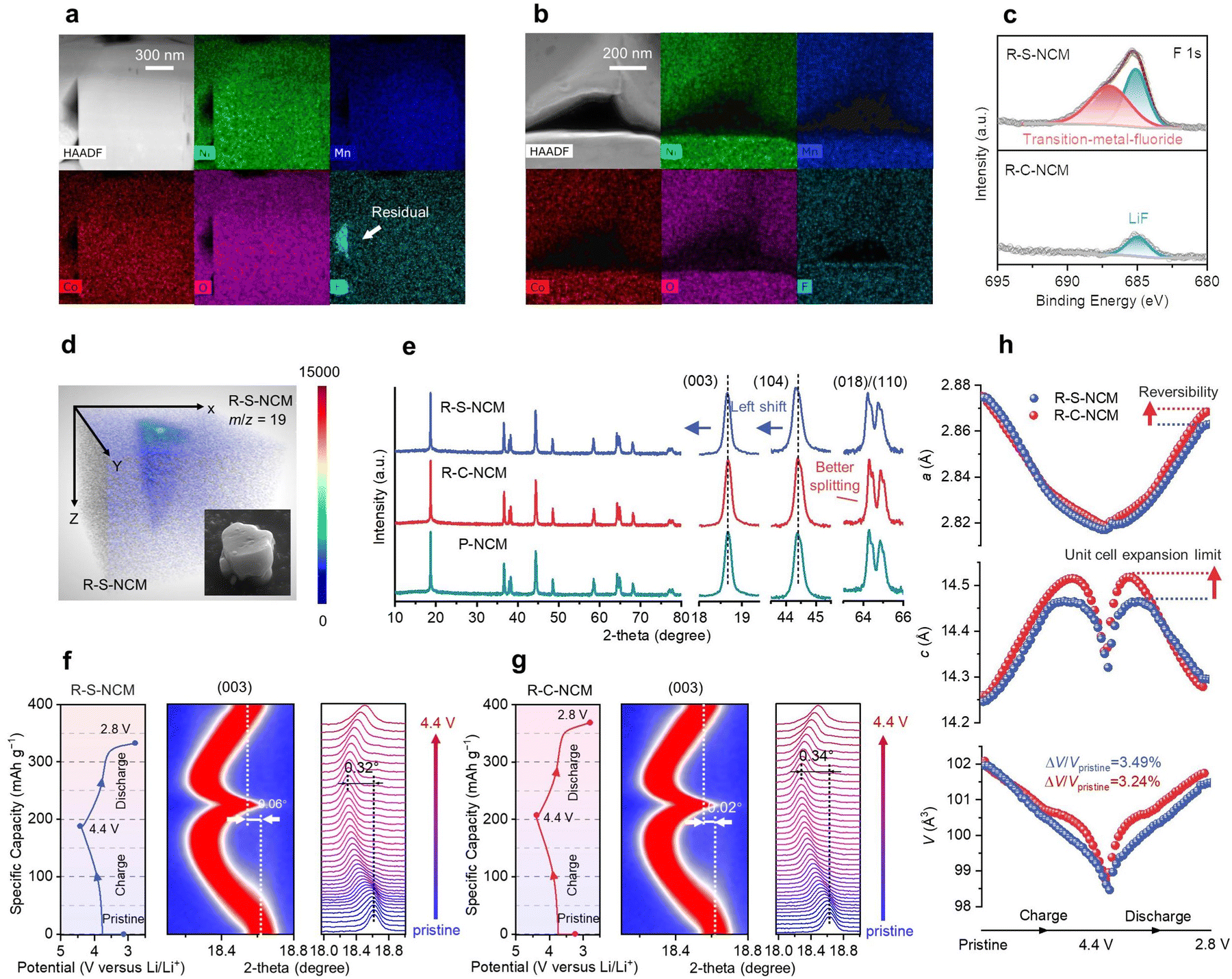 | ||
| Fig. 3 Chemical and structural details of the regenerated cathode materials under the influence of impurities. (a) HAADF-STEM images and (b) corresponding EDS element mappings of R-S-NCM and R-C-NCM particles, focusing on the pores of the packing particles. (c) F 1s XPS high-resolution patterns of R-S-NCM and R-C-NCM powders. (d) Pseudo-three-dimensional distribution of F element and SEM image of the corresponding R-S-NCM particle. (e) Full patterns and characteristic peak comparison of the regenerated and pristine NCM cathodes with Cu Kα radiation at a scan rate of 8° min−1. (f) 1st charge–discharge curves, corresponding XRD patterns of R-S-NCM, and (g) (003) peak position variation when the cell charge from pristine to 4.4 V and comparison with R-C-NCM. (h) Lattice parameters a, c, and the unit cell volume V of R-S-NCM and R-C-NCM in the 1st charge–discharge test according to the refinement. | ||
Furthermore, the crystal structure of the regenerated cathode could also be affected by the residual impurities. As shown in Fig. 3e and Fig. S28 (ESI†), the XRD pattern indicated a layered structure with no impurities phase for both the R-S-NCM and R-C-NCM cathodes. However, the R-C-NCM cathode had a higher (003)/(104) intensity ratio and larger splitting degree for the (018)/(110) peaks compared to R-S-NCM, suggesting its more ideal layered structure similar to P-NCM cathodes. After regeneration accompanied by impurities, the diffraction peaks of R-S-NCM were shifted toward a low-angle direction, indicating the lattice expansion, as supported by the refined parameters (Table S11, ESI†) and in situ experiments (Fig. 2d). Furthermore, in situ XRD was performed during the 1st charge/discharge process for both regenerated cathodes (see Fig. 3f and g). The R-C-NCM cathode showed a higher capacity with a smaller offset (0.02°) of the (003) peak position than the R-S-NCM (0.06°) cathode across the full charge/discharge cycle. The lower structural reversibility of R-S-NCM may be caused by the residual lead side-reactions, which consumed the reversible Li+. In the high-voltage region above 4.4 V in the 1st charge, the R-C-NCM cathode (0.34°) displayed a lager (003) peak offset than R-S-NCM (0.32°), which indicated the better Li+ extracting ability of the R-C-NCM cathode after the purifying treatment. Meanwhile, the XRD refinement (Fig. 3h) also quantitively determined the better reversibility in the plane along the a direction and larger expansion limit along the c direction for the unit cell of R-C-NCM compared with R-S-NCM.46 Moreover, the volume shrinkage (ΔV/VPristine) of R-C-NCM was 3.24%, less than that of R-S-NCM (3.49%). The limited volume change for the unit cell for R-C-NCM could suppress internal stress during long-term charge–discharge processes.
As shown in Fig. 4a and Fig. S30 (ESI†), the initial discharge capacity increased from 154.1 mA h g−1 for R-S-NCM to 171.4 mA h g−1 for R-C-NCM after the purifying treatment, although this was slightly lower than for P-NCM. In Fig. 4b and Fig. S31 (ESI†), the R-C-NCM cathode exhibit 91.7% and 82.1% capacity retention after 100 cycles and 200 cycles, respectively, compared with 91.6% and 78.3% for P-NCM, and 78.6% and 57.5% for R-S-NCM, indicating the R-C-NCM cathode had better cycling stability, even compared to the pristine one. As for the rate performance, the R-C-NCM cathode demonstrated a better high-rate capability (Fig. 4c and Fig. S30, ESI†) at 3C (127.8 mA h g−1) compared to R-S-NCM (69.8 mA h g−1) and P-NCM (108.9 mA h g−1), which was commonly observed on the regenerated NCM cathodes and may be attributed to appropriate F element doping.12,47 The plateau at ∼3.6 V in the voltage profiles (Fig. 4d and e and Fig. S30, ESI†) for R-S-NCM nearly disappears after 100 cycles, suggesting that R-S-NCM had a rising polarization after long-term cycling. Based on the cyclic voltammetry curves at different scan rates and calculations (Fig. S31 and Table S12, ESI†), the fitting line slope for R-S-NCM was found to be the lowest among all the samples. According to the equivalent circuit (Fig. 4f), the calculated impedance values (Rohm, Rint, and Rct) of R-C-NCM (Fig. 4g and h) were 1.4, 51.1, and 307.1 Ω, respectively, and were smaller than that of R-S-NCM. These results indicate the deteriorated kinetics of Li+ transportation due to the residual impurities, especially on the surfaces of the regenerated cathodes. According to the chemical state of the electrode surface (Fig. S32, ESI†), R-C-NCM exposed less inorganic fluoride and more lattice oxide, leading to the suppressed interfacial resistance growing during the long-term cycling. Furthermore, the galvanostatic intermittent titration technique (GITT) test also revealed the kinetic characteristics of the solid phase. The current pulse profile and calculated Li-ion diffusion coefficient (DLi+) after activation are shown in Fig. 4i. The average DLi+ values of R-C-NCM and R-S-NCM were calculated to be 5.78 × 10⁻¹⁴ and 2.99 × 10⁻¹⁴ for the charge process (and 4.56 × 10⁻¹⁴ and 4.29 × 10⁻¹⁴ for the discharge process), suggesting that residual impurities penetrating the interior bulk after regeneration hamper Li+ hopping within the lattice of the NCM cathode, as supported by the observed F element (Fig. 3c and Fig. S27, ESI†).
 | ||
| Fig. 4 Electrochemical deterioration for the regenerated NCM cathodes with impurity residue. (a) Initial galvanostatic charge–discharge curves of R-S-NCM and R-C-NCM at 0.1C (1C = 150 mA h g−1) and (b) long cycling test and capacity retention in a half-cell. (c) Rate capabilities of R-S-NCM and R-C-NCM. Charge–discharge curves of (d) R-S-NCM, (e) R-C-NCM in the voltage range of 2.8–4.4 V (vs. Li/Li+) at different cycles. (f) Equivalent circuit applied in the EIS measurements. Nyquist plots of (g) R-S-NCM and R-C-NCM and (h) fitting results showing the Ohmic resistance (Rohm), interface resistance (Rint), and charge-transfer resistance (Rct). (i) GITT curves and the calculated Li+-diffusion rate of R-S-NCM and R-C-NCM for the 4th cycle number after activation in the same charge–discharge period. The shadow area indicates low Li+ diffusion in a certain voltage range. | ||
Simulation of the fluoride-rich impurities in the reuse and regeneration of the degraded NMC cathodes
According to the above results (Fig. 1d, Fig. S6, S16 (ESI†), and Fig. 4h, i), the migration rate of lithium ions was significantly influenced by the residual impurities; therefore it was crucial to theoretically investigate their influence on capacity delivery in the reuse case and during direct regeneration. Considering the impurities were mostly concentrated at the surface before and after regeneration, and that F-rich residuals could be observed, as shown in Fig. S9 and S10 (ESI†) and Fig. 3c, we chose three representative inorganic components (LiF, Li2CO3, and LiOH) in the CEI layer48 or residual alkali49 to calculate the Li+ diffusion from a thermodynamic perspective, and their structures are shown in Fig. 5a. By maintaining a similar distance and concentration of mobile Li-ions, the diffusion energy barrier of lithium ions (ΔELi+) during the cycling of spent cathodes within the different crystal structures (Fig. 5b) allowed valid comparisons. We found that the ΔELi+ of the LiF phase, as a common inorganic component from CEI, was about 2 and 3 times higher than that of the LiOH and Li2CO3 phases from Fig. 5b. Therefore, this result confirmed that the presence of fluoride-rich impurity residuals on the cathode surface significantly increased the diffusion resistance of Li ions when cycling, ultimately exacerbating the cell impedance and interfacial parasitic reactions (Fig. 1d). To comprehend the larger-scale kinetic characteristics and understand the effect of impurity coatings during heating for regeneration of the spent cathodes, two molecular dynamics models were established for simulating Li+ transportation at 1000 K over 20 ns. Specifically, Model 1 was devised to include an impurity barrier consisting of a LiF layer (Fig. 5c and Fig. S33, ESI†). Through computing the mean square displacement (MSD) of Li atoms and fitting curves (Fig. 5d), we determined that the Li diffusivity (DiffLi+) of Model 1 was 3.33 × 10⁻¹⁰, which was an order of magnitude lower than that of Model 2 (1.00 × 10⁻⁹). The differences in molecular dynamics models under practical conditions suggest that fluoride-rich impurity coatings increase the resistance to Li-ion diffusion into spent cathodes with Li deficiencies during thermo-driven regeneration, leading to inadequate compositional and structural recovery. | ||
| Fig. 5 Role of the F-rich impurities as a blocker in electrochemical and thermochemical Li+ diffusion as ascertained from thermodynamic and kinetic simulations. (a) Illustrations of the selected migration pathways with a similar distance for Li+ inside the crystal lattice of three common components. The initial state, transition state, and final state of Li+ transportation are denoted as IS, TS, and FS, respectively. (b) Calculated energy diffusion barrier for Li ions in selected phases. (c) Two models for stimulating the kinetics of Li transportation in direct regeneration. Model 1 consists of the NCM cathode substrate, the amorphous LiF layer, and Li2CO3 as a lithium source in direct regeneration, which is denoted as NCM‖LiF‖Li2CO3. In Model 2 (NCM‖Li2CO3‖Li2CO3 in short), the middle LiF layer is replaced by a common residual alkali (Li2CO3), which is used to simulate the regeneration of NCM cathodes after cleaning pretreatment. Each shape symbol is the same as for Fig. 5a. (d) MSD of the Li atoms in 20 ns and calculated Li+ diffusivity based on the above model. “E − 9” means 10−9. (e) Mechanism diagram for preventing the NCM cathodes from reusing and directly regenerating under the influence of impurities. | ||
Conclusions
As illustrated in Fig. 5e, the impurity phase containing the F element served as an electro- and thermo-diffusion blocker of Li ions hindering the reuse and direct regeneration of the spent cathode. In the spent cathodes collected by physical pretreatment and collection from used lithium-ion batteries, the ubiquitous electrolyte was decomposed to form an ion barrier with slow ion diffusivity. However, these impurities have long been overlooked in most studies (Table S2, ESI†), mainly due to the use of lab-scale degraded cathodes and fine manual separation pretreatment. In previous studies,12–16,42 the latent impact of the residual impurities on direct regeneration remains untouched because impurities are easily converted into other inconspicuous matter in extreme physical or chemical regeneration environments. Looking ahead, the direct regeneration of next-generation sensitive cathode materials, such as Li-rich Mn-based, Co-free, and ultra-high-Ni cathode materials, faces serious challenges from these latent impurities if they enter the recycling circle. From another perspective, establishing the controlling law for the inherent impurities doping within the closed-loop material flow could instructively enhance the performance of such recycled materials in the future. Moreover, only by revealing the effect of the overlooked impurities or by getting rid of impurities, can evolving technologies and mechanisms for direct regeneration and upcycling be reasonably evaluated.50After high-temperature regeneration, some stubborn products deposit on the surface and infiltrate into bulk phase of the spent cathode, differing from removable additives and making their removal necessary in the above pretreatment step. Therefore, we established a water-based pretreatment method without organic chemical systems to prevent impurities from entering the closed-loop recycling of materials, which is a departure from the traditional organic system. Meanwhile, developing a controllable pretreatment method targeting impurities is essential for clarifying the uncertain impacts of different impurities within cathodes black mass. Even for sensitive advanced cathodes, the minute-level pretreatment method can flexibly modify the process parameters (such as acid concentration, solid-to-liquid ratio, immersion time) and effectively eliminate uniformly distributed impurities while maintaining the bulk structure.
To sum up, we identified that the residual impurities evolved from electrolytes, rather than from the binder as commonly speculated. These represents one of the key chemical defects within spent cathodes, compared to limited compositional and structural defects. Through detailed in situ and ex situ characterizations and theoretical simulation, we found that the F-rich residual impurities can significantly hinder lithium-ion diffusion, but with purifying the residuals, the capacity electrochemical and cycle stability of the regenerated cathode materials were comparable to the pristine level. Our results highlight that the removal of overlooked residual impurities is of vital importance in the direct recycling of batteries and provide a scalable solution to unlock the remarkable potential for directly recycling spent cathodes from practical 250k-miles-serviced spent lithium-ion batteries.
Author contributions
Y. G., Yang L., X. L., L. L., and M. O. conceived the idea and experiment. M. O. and X. L. supervised the research project and provided advice. Y. G. and K. Q. proposed thermodynamic and kinetic modeling for simulating the influence of residual impurities on direct regeneration for cathodes. Y. G., Yang L., and L. S. performed the sample preparation, characterization, and data analysis. Yan L. collected the HAADF-STEM data and analyzed the crystal structure of the sample. G. Z. and T. T. provide help in characterization and experiment. X. R. assisted with the thermal test. B. D. and W. Y. contribute to 2D TXM-XANES characterization and date processing. Y. G., X. L., D. R., L. L., S. L., G. Z., T. T., Y. H., and S. X. contributed to the discussions. C. L. and X. L. contributed to the XRD experiment and explanation of these diffraction data. Y. G. and X. L. wrote the paper. X. L. and D. R. revised and polished the manuscript.Data availability
The data supporting this article have been included as part of the ESI;† further inquiries can be directed to the corresponding author.Conflicts of interest
There are no conflicts to declare.Acknowledgements
We acknowledge the financial support from the Ministry of Science and Technology of China (2022YFB2404300, 2023YFB2503700 and 2022YFE0207900) and the China Postdoctoral Science Foundation (2022TQ0169, 2023M731891, 2022M721782). The authors also thank CALB Group Co., Ltd. for the supply of the degraded NCM cathodes after factory-level separations. In this study, the simulation section gets valuable construction from Dassault Systèmes Co., Ltd.References
- M. E. Biresselioglu, M. Demirbag Kaplan and B. K. Yilmaz, Electric mobility in Europe: A comprehensive review of motivators and barriers in decision making processes, Transp. Res. Part A: Policy Pract., 2018, 109, 1–13 CrossRef.
- L. Trahey, et al., Energy storage emerging: A perspective from the Joint Center for Energy Storage Research, Proc. Natl. Acad. Sci. U. S. A., 2020, 117, 12550–12557 CrossRef CAS.
- IEA. Global EV Outlook 2022, https://www.iea.org/reports/global-ev-outlook-2022 (2022).
- BloombergNEF. Global Energy Storage Market to Grow 15-Fold by 2030. https://about.bnef.com/blog/global-energy-storage-market-to-grow-15-fold-by-2030/ (2022).
- E. Olivetti, G. Ceder, G. Gaustad and X. Fu, Lithium-Ion Battery Supply Chain Considerations: Analysis of Potential Bottlenecks in Critical Metals, Joule, 2017, 1, 229–243 CrossRef.
- W. Yan, et al., Rethinking Chinese supply resilience of critical metals in lithium-ion batteries, J. Cleaner. Prod., 2020, 256, 120719 CrossRef CAS.
- M. A. Alam and R. Sepúlveda, Environmental degradation through mining for energy resources: The case of the shrinking Laguna Santa Rosa wetland in the Atacama Region of Chile, Energy Geosci., 2022, 3, 182–190 CrossRef.
- C. Banza Lubaba Nkulu, et al., Sustainability of artisanal mining of cobalt in DR Congo, Nat. Sustain, 2018, 1, 495–504 CrossRef PubMed.
- W. Mrozik, M. A. Rajaeifar, O. Heidrich and P. Christensen, Environmental impacts, pollution sources and pathways of spent lithium-ion batteries, Energy Environ. Sci., 2021, 14, 6099–6121 RSC.
- R. E. Ciez and J. F. Whitacre, Examining different recycling processes for lithium-ion batteries, Nat. Sustain, 2019, 2, 148–156 CrossRef.
- G. Harper, et al., Recycling lithium-ion batteries from electric vehicles, Nature, 2019, 575, 75–86 CrossRef CAS PubMed.
- J. Ma, et al., Adaptable Eutectic Salt for the Direct Recycling of Highly Degraded Layer Cathodes, J. Am. Chem. Soc., 2022, 144, 20306–20314 CrossRef CAS PubMed.
- G. Qian, et al., Value-creating upcycling of retired electric vehicle battery cathodes, Cell Rep. Phys. Sci., 2022, 3, 100741 CrossRef CAS.
- G. Jiang, et al., Direct Regeneration of LiNi0.5Co0.2Mn0.3O2 Cathode from Spent Lithium-Ion Batteries by the Molten Salts Method, ACS Sustainable Chem. Eng., 2020, 8, 18138–18147 CrossRef CAS.
- P. Xu, et al., Efficient Direct Recycling of Lithium-Ion Battery Cathodes by Targeted Healing, Joule, 2020, 4, 2609–2626 CrossRef CAS.
- W. Liu, M. Liu, F. Ma, M. Qin, W. Zhong, X. Chen, Z. Zeng, S. Cheng and J. Xie, Sci. Bull., 2024, 69, 1697–1705 CrossRef CAS PubMed.
- S&P Global Commodity Insights. FEATURE: Black mass recycling in Europe's battery supply chains. https://www.spglobal.com/commodityinsights/en/market-insights/latest-news/energy-transition/051723-feature-black-mass-recycling-emerges-as-critical-component-in-europes-battery-supply-chains ( 2023).
- W. Yu, Y. Guo, Z. Shang, Y. Zhang and S. Xu, A review on comprehensive recycling of spent power lithium-ion battery in China, eTransportation, 2022, 11, 100155 CrossRef.
- B. L. D. Rinkel, J. P. Vivek, N. Garcia-Araez and C. P. Grey, Two electrolyte decomposition pathways at nickel-rich cathode surfaces in lithium-ion batteries, Energy Environ. Sci., 2022, 15, 3416–3438 RSC.
- X. Wang, G. Gaustad and C. W. Babbitt, Targeting high value metals in lithium-ion battery recycling via shredding and size-based separation, Waste Manage., 2016, 51, 204–213 CrossRef CAS.
- K. Jia, et al., Suppressed lattice oxygen release via Ni/Mn doping from spent LiNi0.5Mn0.3Co0.2O2 toward high-energy layered-oxide cathodes, Nano Lett., 2022, 22, 8372–8380 CrossRef CAS PubMed.
- J. Li, et al., Water-Based Electrode Manufacturing and Direct Recycling of Lithium-Ion Battery Electrodes—A Green and Sustainable Manufacturing System, iScience, 2020, 23, 101081 CrossRef CAS PubMed.
- M. Wang, et al., Challenges in Recycling Spent Lithium-Ion Batteries: Spotlight on Polyvinylidene Fluoride Removal, Glob. Chall., 2023, 7, 2200237 CrossRef.
- V. Gupta, et al., Scalable Direct Recycling of Cathode Black Mass from Spent Lithium-Ion Batteries, Adv. Energy Mater., 2023, 13, 2203093 CrossRef CAS.
- B. J. Ross, et al., Mitigating the Impact of Thermal Binder Removal for Direct Li-Ion Battery Recycling, ACS Sustainable Chem. Eng., 2020, 8, 12511–12515 CrossRef CAS.
- Y. Bi, et al., Reversible planar gliding and microcracking in a single-crystalline Ni-rich cathode, Science, 2020, 370, 1313–1318 CrossRef CAS.
- Y. Liu, J. Harlow and J. Dahn, Microstructural observations of “single crystal” positive electrode materials before and after long term cycling by cross-section scanning electron microscopy, J. Electrochem. Soc., 2020, 167, 020512 CrossRef CAS.
- T. Ohzuku, A. Ueda and M. Nagayama, Electrochemistry and structural chemistry of LiNiO2 (R3m) for 4 volt secondary lithium cells, J. Electrochem. Soc., 1993, 140, 1862–1870 CrossRef CAS.
- W. Yu, Z. Yu, Y. Cui and Z. Bao, Degradation and speciation of Li salts during XPS analysis for battery research, ACS Energy Lett., 2022, 7, 3270–3275 CrossRef CAS.
- J. W. Abbott and F. Hanke, Kinetically corrected Monte Carlo-molecular dynamics simulations of solid electrolytecem, Theory Comput., 2022, 18, 925–934 CrossRef CAS PubMed.
- P. Liu, et al., Effects of incineration and pyrolysis on removal of organics and liberation of cathode active materials derived from spent ternary lithium-ion batteries, Waste Manage., 2023, 169, 342–350 CrossRef CAS.
- X. Liu, L. Yin and D. Ren, et al., In situ observation of thermal-driven degradation and safety concerns of lithiated graphite anode, Nat. Commun., 2021, 12, 4235 CrossRef CAS PubMed.
- Y. Chen, et al., Toxicity identification and evolution mechanism of thermolysis-driven gas emissions from cathodes of spent lithium-ion batteries, ACS Sustainable Chem. Eng., 2019, 7, 18228–18235 CrossRef CAS.
- J. B. DeLisio, et al., Probing the reaction mechanism of aluminum/poly (vinylidene fluoride) composites, J. Phys. Chem. B, 2016, 120, 5534–5542 CrossRef CAS.
- A. Robin and R. B. Ribeiro, Pulse electrodeposition of titanium on carbon steel in the LiF–NaF–KF eutectic melt, J. Appl. Electrochem., 2000, 30, 239–246 CrossRef CAS.
- H. Nagata, N. Mitsugi, K. Shima, M. Tamai and E. M. Haga, Growth of crystalline LiF on CF4 plasma etched LiNbO3 substrates, J. Cryst. Growth, 1998, 187, 573–576 CrossRef CAS.
- H. Zhou, X. Zhao, C. Yin and J. Li, Regeneration of LiNi0.5Co0.2Mn0.3O2 cathode material from spent lithium-ion batteries, Electrochim. Acta, 2018, 291, 142–150 CrossRef CAS.
- A. K. Gupta, R. Bajpai and J. M. Keller, PVDF: PI nano composite films: Mechanical, FT-IR, XRD, AFM and hydraulic study, J. Polym. Res., 2008, 15, 275–283 CrossRef CAS.
- S. Li, G. Qian, X. He, X. Huang, S. J. Lee, Z. Jiang, Y. Yang, W. N. Wang, D. Meng, C. Yu, J. S. Lee, Y. S. Chu, Z. F. Ma, P. Pianetta, J. Qiu, L. Li, K. Zhao and Y. Liu, Nat. Commun., 2022, 13, 1–10 CAS.
- I. A. Shkrob, et al., Chemical Weathering of Layered Ni-Rich Oxide Electrode Materials: Evidence for Cation Exchange, J. Electrochem. Soc., 2017, 164, A1489 CrossRef CAS.
- I. Hamam, N. Zhang, A. Liu, M. B. Johnson and J. R. Dahn, Study of the Reactions between Ni-Rich Positive Electrode Materials and Aqueous Solutions and their Relation to the Failure of Li-Ion Cells, J. Electrochem. Soc., 2020, 167, 130521 CrossRef CAS.
- FactSage FTsalt salt database. List of systems and phases. https://www.factsage.cn/fact/documentation/ftsalt/ftsalt_list.htm ( 2023).
- Y. Shi, et al., Ambient-pressure relithiation of degraded LixNi0.5Co0.2Mn0.3O2 (0 < x < 1) via eutectic solutions for direct regeneration of lithium-ion battery cathodes, Adv. Energy Mater., 2019, 9, 1900454 CrossRef.
- S. Deng, et al., Structural Evolution and Formation Mechanism of LiNiO2 During High-Temperature Solid-State Synthesis, J. Electrochem. Energy Convers. Storage, 2019, 16, 031004 CrossRef CAS.
- T. Zhang, et al., Surface analysis of cobalt-enriched crushed products of spent lithium-ion batteries by X-ray photoelectron spectroscopy, Sep. Purif. Technol., 2014, 138, 21–27 CrossRef CAS.
- W. Li, H. Y. Asl, Q. Xie and A. Manthiram, Collapse of LiNi1−x−yCoxMnyO2 lattice at deep charge irrespective of nickel content in lithium-ion batteries, J. Am. Chem. Soc., 2019, 141, 5097–5101 CrossRef CAS PubMed.
- U. H. Kim, et al., Cation ordered Ni-rich layered cathode for ultra-long battery life, Energy Environ. Sci., 2021, 14, 1573–1583 RSC.
- S. Park, et al., Ionic conductivity and mechanical properties of the solid electrolyte interphase in lithium metal batteries, Energy Mater., 2023, 3, 300005 CAS.
- Y. Kim, H. Park, J. H. Warner and A. Manthiram, Unraveling the intricacies of residual lithium in high-Ni cathodes for lithium-ion batteries, ACS Energy Lett., 2021, 6, 941–948 CrossRef CAS.
- G. D. J. Harper, Upcycle for enhanced performance, Nat. Sustain., 2023, 6, 725–726 CrossRef.
Footnotes |
| † Electronic supplementary information (ESI) available. See DOI: https://doi.org/10.1039/d4ee03021d |
| ‡ These authors contributed equally. |
| This journal is © The Royal Society of Chemistry 2025 |