
Design and development of 3D printed shape memory triphasic polymer-ceramic bioactive scaffolds for bone tissue engineering†
Mohammad Aftab Alam
Ansari
abc,
Pooja
Makwana
d,
Bindiya
Dhimmar
d,
Rajesh
Vasita
de,
Prashant Kumar
Jain
*b and
Himansu Sekhar
Nanda
 *ace
*ace
aBiomaterials and Biomanufacturing Laboratory (Formerly Biomedical Engineering and Technology Lab), Mechanical engineering discipline, PDPM Indian Institute of Information Technology, Design & Manufacturing Jabalpur, Jabalpur, India. E-mail: himansu@iiitdmj.ac.in
bFused Filament Fabrication Laboratory, Mechanical engineering discipline, PDPM Indian Institute of Information Technology, Design & Manufacturing Jabalpur, Jabalpur, India. E-mail: pkjain@iiitdmj.ac.in
cInternational Centre for Sustainable and Net Zero Technologies, PDPM-Indian Institute of Information Technology Design and Manufacturing (IIITDM) Jabalpur, Dumna Airport Road, Jabalpur-482005, MP, India
dSchool of Life Sciences, Central University of Gujarat, Gandhinagar, 382030, India
eTerasaki Institute for Biomedical Innovation (TIBI), 21100 Erwin St., Los Angeles, CA 91367, USA
First published on 11th June 2024
Abstract
Scaffolds for bone tissue engineering require considerable mechanical strength to repair damaged bone defects. In this study, we designed and developed mechanically competent composite shape memory triphasic bone scaffolds using fused filament fabrication (FFF) three dimensional (3D) printing. Wollastonite particles (WP) were incorporated into the poly lactic acid (PLA)/polycaprolactone (PCL) matrix as a reinforcing agent (up to 40 wt%) to harness osteoconductive and load-bearing properties from the 3D printed scaffolds. PCL as a minor phase (20 wt%) was added to enhance the toughening effect and induce the shape memory effect in the triphasic composite scaffolds. The 3D-printed composite scaffolds were studied for morphological, thermal, and mechanical properties, in vitro degradation, biocompatibility, and shape memory behaviour. The composite scaffold had interconnected pores of 550 μm, porosity of more than 50%, and appreciable compressive strength (∼50 MPa), which was over 90% greater than that of the pristine PLA scaffolds. The flexural strength was improved by 140% for 40 wt% of WP loading. The inclusion of WP did not affect the thermal property of the scaffolds; however, the inclusion of PCL reduced the thermal stability. An accelerated in vitro degradation was observed for WP incorporated composite scaffolds compared to pristine PLA scaffolds. The inclusion of WP improved the hydrophilic property of the scaffolds, and the result was significant for 40 wt% WP incorporated composite scaffolds having a water contact angle of 49.61°. The triphasic scaffold exhibited excellent shape recovery properties with a shape recovery ratio of ∼84%. These scaffolds were studied for their protein adsorption, cell proliferation, and bone mineralization potential. The incorporation of WP reduced the protein adsorption capacity of the composite scaffolds. The scaffold did not leach any toxic substance and demonstrated good cell viability, indicating its biocompatibility and growth-promoting behavior. The osteogenic potential of the WP incorporated scaffolds was observed in MC3T3-E1 cells, revealing early mineralization in pre-osteoblast cells cultured in different WP incorporated composite scaffolds. These results suggest that 3D-printed WP reinforced PLA/PCL composite bioactive scaffolds are promising for load bearing bone defect repair.
 Himansu Sekhar Nanda | Himansu Sekhar Nanda, PhD, received his PhD in Materials Science and Engineering from the International Graduate School of National Institute for Materials Science, Japan, under the supervision of Prof. Guoping Chen (President Elect-, TERMIS AP). He was a postdoctoral fellow in King Abdullah University of Science and Technology, Saudi Arabia, and a postdoctoral research fellow at Nanyang Technological University Singapore. Currently, he is working as an Assistant Professor Grade 1 at the Discipline of Mechanical Engineering, Indian Institute of Information Technology Design and Manufacturing (IIITDM), Jabalpur, India, and heading the Biomaterials and Biomanufacturing Laboratory (formerly Biomedical Engineering and Technology Laboratory) at IIITDM. He is also the founding head of International Center for Sustainable and Net Zero Technologies. He holds an adjunct appointment as an Assistant Professor (visiting) at the College of Materials Science and Engineering, BUCT, Beijing, and a Visiting Scientist at the State Key Laboratory of Molecular Engineering of Polymers, Fudan University, China. He was a research scientist at Terasaki Institute for Biomedical Innovation (TIBI), Los Angeles, USA, and now he is an affiliate faculty member at TIBI. His current research interests include 3D printing of biomaterials, tissue engineering, biomechanics and sustainable biomanufacturing. |
1. Introduction
Bone fractures, including large segmental bone defects caused by several diseases or accidental injuries, may require partial or total replacement/regeneration, and they are considered a significant source of patient morbidity.1 Bone is the second most transplanted tissue in the world, and the annual cost of treatment is estimated to be ∼$5 billion in the US alone.1 Currently, autograft, allograft, and xenograft are considered “gold standard” treatments for critical-size bone defects, and they are most often harvested from a patient's iliac crest, fibula, skull, or mandible.2 However, their success probability is subjected to multiple factors, and therefore, they are prone to new injuries/infections and morbidities.3,4 Particularly, the shaping and fixing of the typical rigid autograft into the defect site are difficult, resulting in an ill-fitting interface and poor contact between the surrounding bone tissue and the graft. Such ill-fitting increases the risk of graft resorption. To circumvent these challenges, bioengineering and materials science combined with additive manufacturing have constantly been advancing to develop patient-specific biological substitutes to induce and promote natural tissue repair by using cell and tissue engineering approaches.5–8 Bone tissue engineering (BTE) uses three-dimensional porous structures (called scaffolds) loaded with cells, biologically active molecules, and growth factors to promote cell evolution for reconstruction of functional bone.9,10Moreover, scaffolds should be osteoconductive to promote cell migration and allow neotissue infiltration while being mechanically competent to withstand the body load. The implanted scaffold must also form close contact with the adjacent bone tissue to promote osseointegration.11 Traditional fabrication techniques (such as freeze-drying, salt leaching, solvent casting, etc.) partially fulfill these complex requirements. The scaffold produced through these techniques lacks sufficient mechanical strength, proper fitting into the defect site, porosity, and pore interconnectivity to promote proper vascularisation.
With the advancement in additive manufacturing (AM) techniques, which offer endless manufacturing possibilities, the fabrication of biomimetic scaffolds with structural complexities similar to natural bone has become a reality today. While it also offers a variety of biomaterials to be used, shape memory scaffolds with shapes conforming to the defect site can also be produced by proper selection of biomaterials for better osseointegration. Therefore, AM is a promising manufacturing technique for biomimetic scaffolds for BTE application. The fused filament fabrication method (FFF) is a cost-effective, rapid, and readily available 3D printing process that offers the flexibility to use tailored biomaterials based on the scaffold application.12,13 There is vast literature indicating FFF as a simple and versatile approach for fabricating polymer-based scaffolds for TE applications.14 Even though there is limited availability of medical grade feedstock for FFF 3D printers for its direct application in BTE, composite feedstock with tailored composition can be developed through a wire-drawing extruder, opening the door for innovation in biomaterials for FFF-based 3D printers.12 Medical grade poly(lactic acid) (PLA) is frequently reported in the literature and remains a popular material of choice for various medical applications, including tissue engineering15,16 and bone fixation devices,17 due to its well-documented biocompatibility, complete biodegradability, and high stiffness resulting from its relatively high glass transition temperature (Tg).18 The semicrystalline polyester poly(ε-caprolactone) (PCL) is another polymer in the row, which is soft, biocompatible, and biodegradable.17,19 It has a rubbery amorphous phase at room temperature because of its glass transition temperature (Tg) around −60 °C and it has a melting temperature (Tm) range of 55–70 °C. PLA and PCL share comparable characteristics, such as good biocompatibility and biodegradability. PCL is compatible with both hard and soft tissue and degrades slowly inside the human body over a period of 24 to 36 months.20 It has low toxicity, and its intrinsic high flexibility nature makes it a suitable candidate to be added with other brittle materials to promote fluidity, flexibility, and impact resistance. Fortelny et al. summarized several techniques for toughening PLA.17 Blending a brittle polymer with soft, ductile polymers is generally the most efficient method for improving its toughness.9,17,21 Neat PLA exhibits low impact strength. However, PLA/PCL blends exhibit enhanced impact strength while maintaining biocompatibility and biodegradability.17,22 Interestingly, the PLA/PCL blend also offers shape memory behavior, i.e., the ability of the material to change its initial shape under certain external stimuli, usually the temperature. The presence of two different phases, i.e., PLA and PCL, where PLA acts as the net point while PCL acts as the switching phase, allows it to conform to the shape of the defect site upon thermal stimulus.2 Ma et al. fabricated a shape memory composite using PLA and PCL for biomedical applications.23 Addition of PCL lowered the glass transition temperature from 67.2° to 55.2 °C, and the blend offered outstanding shape memory behavior. The response time was less than 1.2 s, and the shape fixation/recovery rate was above 92%. Similarly, Wang et al. studied the effect of different compositions of PLA/PCL on the shape memory property and found that PCL/PLA composition with a ratio of 3![[thin space (1/6-em)]](https://www.rsc.org/images/entities/char_2009.gif) :1 offered the highest shape memory recovery ratio of 95.37% at a programming temperature of 90 °C.24 While these shape memory blends offer good biocompatibility and complete biodegradability, they lack sufficient mechanical strength and osteoconductivity to promote bone regeneration.25–28 Despite significant progress, scaffolds made from these polymers are also susceptible to bacterial infection, notably osteomyelitis, which leads to the replacement of ∼2–5% of the total implant in the patient through additional surgery. Polymeric scaffolds also pose major shortcomings for use in BTE applications, such as differences in their compositional properties as compared to bone, poor/lack of adhesion with bone cells, the release of acidic by-products, which may cause inflammatory responses inside the human body, and low mechanical strength.29 Therefore, polymers are reinforced with bioactive fillers to enable proper tissue adhesion with the organic phase. Bioactive glasses and glass ceramics having a mineral composition similar to bone are commonly reinforced into the polymeric phase to improve the bone-bonding capability of materials in vivo. It has been found from the literature that CaO and SiO2 are the two major bone-bonding components responsible for the formation of apatite layers at the damaged tissue site.30–32 Therefore, CaO–SiO2 containing wollastonite is considered a potential bioactive filler in the preparation of biodegradable biocomposites for BTE applications. Calcium silicate ceramics, in particular wollastonite with the chemical formula CaSiO3, constitute one of the largest groups of bioceramics for BTE due to their excellent biocompatibility, bioactivity, and antibacterial properties.33–35 Wollastonite is one of the most explored silicate bioceramics due to its comparatively rapid biomineralization capabilities than other bioceramics. It can induce new apatite and bone formation comparatively faster than other bio-glass and ceramics. Goswami et al. studied the in vitro biocompatibility of wollastonite-reinforced PLA porous foam by seeding osteoblast cells.30 The contact angle result showed enhanced hydrophilicity in the composite containing 8 wt% of filler having a 72° water contact angle (WCA). A similar result was observed for osteoblast cell attachment with maximum cell growth on the surface of foam containing 8 wt% of wollastonite as observed from MTT assay data and SEM imaging. Abudhahir et al. synthesized composite scaffolds by combining PLA with wollastonite through electrospinning techniques.33 The result depicted that the inclusion of wollastonite inhibited the microbial growth on the composite scaffold, with a zone of inhibition around 2.46 and 2.26 mm against E. coli and S. aureus respectively, while promoting bone synthesis through cell proliferation and differentiation.
:1 offered the highest shape memory recovery ratio of 95.37% at a programming temperature of 90 °C.24 While these shape memory blends offer good biocompatibility and complete biodegradability, they lack sufficient mechanical strength and osteoconductivity to promote bone regeneration.25–28 Despite significant progress, scaffolds made from these polymers are also susceptible to bacterial infection, notably osteomyelitis, which leads to the replacement of ∼2–5% of the total implant in the patient through additional surgery. Polymeric scaffolds also pose major shortcomings for use in BTE applications, such as differences in their compositional properties as compared to bone, poor/lack of adhesion with bone cells, the release of acidic by-products, which may cause inflammatory responses inside the human body, and low mechanical strength.29 Therefore, polymers are reinforced with bioactive fillers to enable proper tissue adhesion with the organic phase. Bioactive glasses and glass ceramics having a mineral composition similar to bone are commonly reinforced into the polymeric phase to improve the bone-bonding capability of materials in vivo. It has been found from the literature that CaO and SiO2 are the two major bone-bonding components responsible for the formation of apatite layers at the damaged tissue site.30–32 Therefore, CaO–SiO2 containing wollastonite is considered a potential bioactive filler in the preparation of biodegradable biocomposites for BTE applications. Calcium silicate ceramics, in particular wollastonite with the chemical formula CaSiO3, constitute one of the largest groups of bioceramics for BTE due to their excellent biocompatibility, bioactivity, and antibacterial properties.33–35 Wollastonite is one of the most explored silicate bioceramics due to its comparatively rapid biomineralization capabilities than other bioceramics. It can induce new apatite and bone formation comparatively faster than other bio-glass and ceramics. Goswami et al. studied the in vitro biocompatibility of wollastonite-reinforced PLA porous foam by seeding osteoblast cells.30 The contact angle result showed enhanced hydrophilicity in the composite containing 8 wt% of filler having a 72° water contact angle (WCA). A similar result was observed for osteoblast cell attachment with maximum cell growth on the surface of foam containing 8 wt% of wollastonite as observed from MTT assay data and SEM imaging. Abudhahir et al. synthesized composite scaffolds by combining PLA with wollastonite through electrospinning techniques.33 The result depicted that the inclusion of wollastonite inhibited the microbial growth on the composite scaffold, with a zone of inhibition around 2.46 and 2.26 mm against E. coli and S. aureus respectively, while promoting bone synthesis through cell proliferation and differentiation.
The high aspect ratio and acicular nature of wollastonite in the implanted organic scaffolds enable better bone-bonding ability with bone due to its chemical similarity with bone minerals while providing sufficient mechanical integrity to the scaffolds in the physiological environment.34,36–38 Additionally, the alkaline degradation of the biopolymer is neutralized by the mineral's alkaline degradation, helping to minimize inflammation inside the human body. Therefore, wollastonite is a promising functional filler for thermoplastic composites, replacing other expensive reinforcements such as glass fiber and calcium carbonate for biomedical applications.39–42 The reinforcing abilities and biocompatibility of wollastonite-reinforced polymer biocomposites have attracted considerable attention from researchers and industries. The relatively high aspect ratio and hardness of wollastonite significantly improve the resulting composite's overall mechanical strength, particularly in terms of better impact resistance and flexural properties. Therefore, it has attracted great research interest as an alternative low-cost bioceramic material for biomedical applications such as drug delivery, bone repair, and tissue engineering. A study by Padmanabhan and coworkers revealed that incorporating wollastonite significantly improved the compressive strength of the hydroxyapatite scaffold by incorporating 50 wt% wollastonite phase.37 The acicular form of wollastonite plays a major role in improving mechanical strength by properly locking with HA particles. The needle-shaped microstructure of the WPs makes the surface more rough and provides more surface area for the cells to attach, proliferate, and differentiate. The increased surface area facilitates the mineralization process by properly locking with HA particles.
In the present study, to substantially enhance the toughness of PLA with minimum reduction in stiffness, the preparation of PLA/PCL blends was proposed, where PLA is a major component, PCL is a minor component, and wollastonite particles (WP) act as an osteoconductive ceramic phase to harness the mechanical and biological properties of the 3D-printed triphasic composite scaffolds. The soft phase PCL in the triphasic scaffold should act as a switching agent to induce shape memory behavior of the scaffolds at the defect site to further attribute to the shape conformation.43 It is hypothesized that the inclusion of WP in the PLA/PCL blend would result in better mechanical properties of the resulting scaffolds while inducing considerable new bone formation due to the incorporation of calcium (Ca) and silicon (Si) (Ca2+, SiO32−) ions in abundance. Moreover, in vitro cell culture study and protein adsorption study have been performed to investigate the ability of the proposed 3D printed triphasic scaffold to support bioactivities such as cell adhesion, proliferation, differentiation, and subsequent bone regeneration potential. It is worth mentioning that the expected improvement in strength is either equivalent or even superior to the required mechanical strength in load-bearing defects, which would open the door for manufacturing 3D composite scaffolds for bone regeneration and repair of large segmental bone defects.
2. Materials and methods
2.1. Materials
PLA pellets (2003D grade) (molecular weight 60000–80000 g mol−1) were kindly supplied by NU OSSA Medi Equip Pvt. Ltd (India). The PLA pellet has a melt flow index of 5–7 (g/10 min, 190 °C, 2.16 kg, ASTM D1238), a glass transition temperature of 60 °C, and a melting temperature of 160 °C. Polycaprolactone (PCL) filament with the trade name Facilan™ PCL 100 was purchased from 3D4Makers, Netherlands. It has a relative molecular weight (Mw) of 50000 g mol−1, a melt flow index of 3–5 (g/10 min, 160 °C, 2.16 kg, ASTM D1238), and a glass transition temperature of −60 °C. Wolkem Industries Pvt. Ltd kindly provided the wollastonite powder with the trade name Kemolit KWB-1010. The MC3T3-E1 Subclone 4, pre-osteoblast cells; Mouse were purchased from the ATCC, and a passage number of 20 to 25 was used for the cell culture experiments. Bovine serum albumin (BSA), dimethyl sulfoxide (DMSO), and minimum essential medium Eagle – alpha modification (α-MEM) were purchased from Himedia Laboratories. p-Nitrophenyl phosphate (PpNPP) and 3-(4,5-dimethylthiazol-2-yl)-2,5-diphenyl tetrazolium bromide (MTT) were purchased from Sigma-Aldrich. Fetal bovine serum (FBS) and antibiotic–antimycotic were purchased from Gibco. Pierce™ BCA protein assay kits were purchased from Thermo Scientific™. The primary antibodies RUNX2 and osteocalcin (OCN) and secondary antibodies Alexa fluor 488 goat A and CY5 goat anti-mouse IGG(H + L) were purchased from Invitrogen.
2.2. Methods
| Sl. no. | Samples | Weight (%) | Sample-ID |
|---|---|---|---|
| 1. | PLA/PCL | 100/0 | PW0 |
| 2. | PLA/PCL/wollastonite | 80/20/5 | PPW5 |
| 3. | PLA/PCL/wollastonite | 80/20/10 | PPW10 |
| 4. | PLA/PCL/wollastonite | 80/20/20 | PPW20 |
| 5. | PLA/PCL/wollastonite | 80/20/40 | PPW40 |
The prepared paste was poured on a flat glass plate uniformly to obtain a thin composite film and kept under a laboratory hood to evaporate the organic solvent. The composite film was shredded into a pellet form (average size of 2–5 mm) for processing into a filament form. The pellets were fed into a single screw wire-drawing extruder (Filastruder, China) to obtain the filaments. This wire extruder has a screw geometry specially designed for materials and additives blending, according to its manufacturer. It comes with two heat zones, one near the hopper (zone-1) and the other near the nozzle (zone-2), and a high torque motor that pushes the pellet into the heated barrel to produce a filament of 1.75 mm diameter. The optimal operational condition for filament extrusion was determined experimentally for each group of composites before the final production of the filaments for the present work and is summarized in Table 2. The materials were extruded twice through the extruder to improve the dispersion of fillers in the composites. The extruded filament was air-cooled at room temperature.
| Samples | Zone-1 temperature (°C) | Zone-2 temperature (°C) |
|---|---|---|
| PW0 | 180 | 150 |
| PPW5 | 180 | 150 |
| PPW10 | 170 | 150 |
| PPW20 | 170 | 150 |
| PPW40 | 170 | 150 |
The cylindrical test specimen of Ø15 × 10 mm was 3D printed with a layer height of 0.2 mm and nozzle temperature varying from 140 °C to 210 °C with an increment of 10 °C to obtain an optimal printing temperature. The printing speed and the bed temperature were maintained constant at 60 mm s−1 and 60 °C, respectively. The printing parameters used for scaffold fabrication are summarised in Table 3. All the scaffolds were printed at 0.2 mm layer height and 100% infill density with a linear infill pattern. To ensure correct filament extrusion during the printing of specimens, the skirt was placed at 5 mm from the specimen body. The printing was done with a cooling fan at approximately 80% for proper adhesion between the layers. The printed scaffolds were examined visually for any layer fusion or layer delamination. The print quality of a 3D-printed specimen is examined through its dimensional accuracy. The closer the tolerance of the printed specimen with the CAD model, the better the print quality. A digital Vernier caliper was used to measure and compare the dimensional accuracy of the 3D printed scaffold with the designed CAD model.
| Printer setting | Value |
|---|---|
| Nozzle diameter (mm) | 0.4 |
| Layer height (mm) | 0.2 |
| Infill (%) | 100 |
| Infill pattern | Line |
| Printing speed (mm s−1) | 60 |
| Nozzle temperature (°C) | 160, 180 |
| Bed temperature (°C) | 60 |
3. Characterization, testing, and analysis
3.1. Scaffold imaging and dimensional accuracy
The scaffold images were captured using a Nikon Eclipse LV150 digital microscope with a 2.5X objective. NIS Elements software (Nikon Inc., Melville, NY, USA) was used to acquire images and record necessary feature measurements. The dimensional accuracy of the printed scaffolds was evaluated using a digital Vernier caliper in the X-Y plane. The structure and incorporation of WP into the PLA/PCL matrix were determined using the SEM images. The triphasic PPW scaffolds were cut into small pieces for SEM analysis. The samples were gold–palladium sputter-coated for 45 s. The images were captured with a Carl Zeiss SEM microscope (EVO 18) at 5 kV voltage.The composite scaffolds’ pore morphology, surface morphology, particle size, microstructures, and elemental analysis were characterized by scanning electron microscopy (SEM, TM3030, HITACHI, Japan) coupled with energy-dispersive X-ray spectroscopy in secondary electron mode. The surface of the scaffolds was gold-coated to avoid electrostatic charging. The porosity of the scaffolds was determined using the Archimedes methods.
| Porosity (%) = (W3 − W1)/(W3 − W2) × 100 | (1) |
3.2. Melt flow behavior
The melt flow index (MFI) of the PPW triphasic composites was investigated using a melt flow indexer (oracle equipment's LTD, India). For calculating the MFI, 3–5 g of composite samples from each group was loaded into the hot cylindrical capillary and forced to flow through it using a piston actuated by 2.16 kg weight, as per ASTM D1238 and ISO1133 standards. The MFI (g/10 min) was calculated based on the following equation: | (2) |
3.3. X-ray diffraction analysis
The X-ray diffraction (XRD) of wollastonite powder and the PPW triphasic composite scaffolds was measured using the Ultima diffractometer (Japan) in the range of 10° to 100° using a scanning rate of 5° min−1 with a Co Kα radiation source.3.4. Thermal analysis
The thermal properties of the composite materials were investigated using differential scanning calorimetry (DSC) and thermogravimetry analysis (TGA). DSC (NETZSCH DSC200F3, Germany) was performed to analyze the melting and crystallization temperature of the composites under an inert atmosphere. Samples were heated from room temperature to 200 °C at 10 °C min−1 increments and held for 5 m to remove the thermal history. The samples were then cooled to room temperature (30 °C) at a cooling rate of 10 °C min−1 and heated again to 200 °C at 10 °C min−1. The glass transition temperature (Tg) and melting temperature (Tm) were determined from the scanning results. The temperature employed for the extrusion of the composite filament and fabrication of the scaffold was determined from the result of the DSC analysis. The thermal stability of the composites was determined using TGA analysis using a heating rate of 10 °C min−1 in the temperature range of 27–600 °C.3.5. Fourier transform infrared (FTIR) spectroscopy
The intermolecular interaction of the compositions present in the composite scaffolds was determined using FTIR spectroscopy. Fourier-transformed infrared spectra of all the composite scaffolds were recorded using an FTIR spectrometer (Frontier, USA) at room temperature in the wavenumber range of 450–4000 cm−1. The test was carried out on a thin film obtained by melting the filament on a thin glass plate.3.6. Mechanical testing
A Tinius Oslem universal testing machine (UTM) equipped with a 5 kN load cell with a deformation rate of 1 mm min−1 was used to analyze the mechanical stability of the scaffolds. Five specimens from each material composition were tested along the vertical z direction. The wet compression test of the specimen was also performed as an in vitro study. All the samples were soaked in phosphate-buffered saline solution (PBS) at pH 7.4 for 28 days in a shaking water bath (Remi RWB 6). The samples were removed and wiped with blotting paper to remove excess media before testing. Three-point bending tests were performed for the flexural characterization. The test was performed on porous samples with dimensions of 3 mm × 5 mm × 25 mm at a crosshead speed of 0.2 mm min−1 using a 1 kN load cell. The compressive modulus was obtained from the initial linear region of the stress–strain curve.3.7. In vitro degradation study
The in vitro hydrolytic degradation of the composite scaffolds was carried out by immersing them in PBS solution (pH = 7.4) at 37 °C in an incubator with uniform oscillation. The degradation properties were assessed by studying scaffolds’ mass loss and morphology change at different degradation time points. The PBS medium was replaced weekly for 28 days. At a regular interval of seven days, scaffolds were removed and rinsed with deionized (DI) water thrice to remove salts and other impurities. These scaffolds were then blotted using filter paper and dried under vacuum at 30 °C for 12 h, and the weight was recorded. The mass loss was determined using the following equation:| Weight loss (%) = (Wdry − Wt)/Wdry × 100 | (3) |
3.8. Shape memory behavior
The shape memory effect of the scaffolds was analyzed through a compression test under normal room temperature. The original height of the scaffold was recorded as L0. The scaffold was compressed to 40% strain of its original height (Lm). The load was removed to allow the scaffolds to reach an equilibrium state. This height was recorded as Lf. After that, the scaffold with a deformed fixed shape was placed on a heat bed plate and heated to 60 °C to initiate the shape regain property. The final height of the scaffold attained after heating was recorded and the image was captured. This final recovered height of the scaffold was termed as Lr. The shape fixity ratio (Rf), i.e., the ability to fix the temporary shape, and the shape recovery ratio (Rr), i.e., the ability to recover the initial shape, were calculated according to the following equations:46| Rf = (Lo − Lm)/(Lo − Lf) × 100% | (4) |
| Rr = (Lr − Lf)/(Lo − Lf) × 100% | (5) |
3.9. Water contact test
The hydrophilicity of the composite scaffolds was determined using a water contact angle goniometer (JC2000DM; Shanghai Zhongchen Digital Technology Apparatus, China). The water contact angle of the scaffolds was measured at five random positions using the sessile drop method and the average with standard deviation (SD) of the results was obtained.3.10. Protein adsorption
Protein adsorption on the triphasic WP reinforced PLA/PCl composite scaffolds was determined using a BCA kit. The samples were placed in 1 mg mL−1 BSA solution for one hour. After that, the samples were washed with distilled water thrice. A working solution of the BCA reagent was added to the scaffold and incubated at 37 °C for 30 m. The absorbance was measured at 562 nm with a multimode plate reader (Biotek Synergy H1).3.11. In vitro cell culture study
MC3T3-E1 (pre-osteoblast) cells were cultured in α-MEM medium with 10% FBS at 37 °C in 5% CO2. The triphasic WP reinforced PLA/PCL scaffolds were sterilized with 70% isopropanol for 1 h, followed by three times washing with distilled water. The dried scaffold was further sterilized using ethylene oxide in an ETO sterilizer (model no: MAC-A35). Before culture studies, the scaffolds were treated with 30% BSA overnight.:200) and OCN (1:200) markers were used for staining the cells, followed by labeling the RUNX2 (anti-rabbit Alexa 488) and OCN (anti-mouse CY5) markers by secondary antibody for 2 h. Phalloidin (1 μL/1 mL) and DAPI (2 μg mL−1) were used as counterstains to stain the actin filament and nucleus of the cells. The images were taken with a confocal microscope (LSM 780) at 20X magnification.
3.12. Statistical analysis
All numerical data were expressed as the mean value ± standard deviation (SD). Statistical analysis was performed using a one-way variance analysis (ANOVA) using Microsoft Excel 2020. The difference was considered significant at p < 0.05.4. Results and discussion
4.1. Scaffold dimensional accuracy
The internal architecture of a scaffold is very important from the mechanical and biological standpoint. The 3D printed pure PLA and WP based composite scaffolds are shown in Fig. 1a. All the 3D printed scaffolds showed similar geometrical structures, irrespective of the varying levels of WP, signifying the ability of the composite filament to print the scaffolds without any failure. The edge-to-edge outer dimensional accuracy for PLA (PW0), PPW5, PPW10, PPW20, and PPW40 scaffolds was 15.07 ± 0.12 mm, 15.17 ± 0.29 mm, 14.44 ± 0.88 mm, 15.27 ± 0.44 mm, and 14.68 ± 0.37 respectively. These deviations were within ∼5% of the target 15 mm designed external geometry. The pore size and porosity govern the cell seeding, proliferation, and cell distribution throughout the scaffolds. Therefore, we measured and reported the average value of pore size and strand diameter here. These scaffolds were designed for a pore size of 600 μm and a strand width of 640 μm. The actual value of the 3D printed scaffold dimensions was measured by running ImageJ Version 1.53c (https://imagej.nih.gov/ij/) macro code on the microscopic images of scaffolds, post-printing. As seen in Fig. 1b and c, pure PLA scaffold dimensions agreed with the designed CAD model. However, the reinforced composite scaffold exhibited nominal deviation in the actual dimensions of the scaffolds. The mean pore size of the scaffolds follows the order PLA (553 μm) > PPW5 (589 μm) > PPW10 (478 μm) > PPW20 (485 μm)> PPW40(425 μm). The desired pore size for BTE typically ranges from 300 to 900 μm.47,48 This variation in dimension could be attributed to the die-swelling mechanism of the particle-reinforced polymer, which, upon extrusion from nozzles, swells, exhibiting a typical viscoelastic polymer property.14,47,49 In this study, the developed WP reinforced composite scaffolds with suitable pore size and overall dimensions were fabricated with good dimensional accuracy.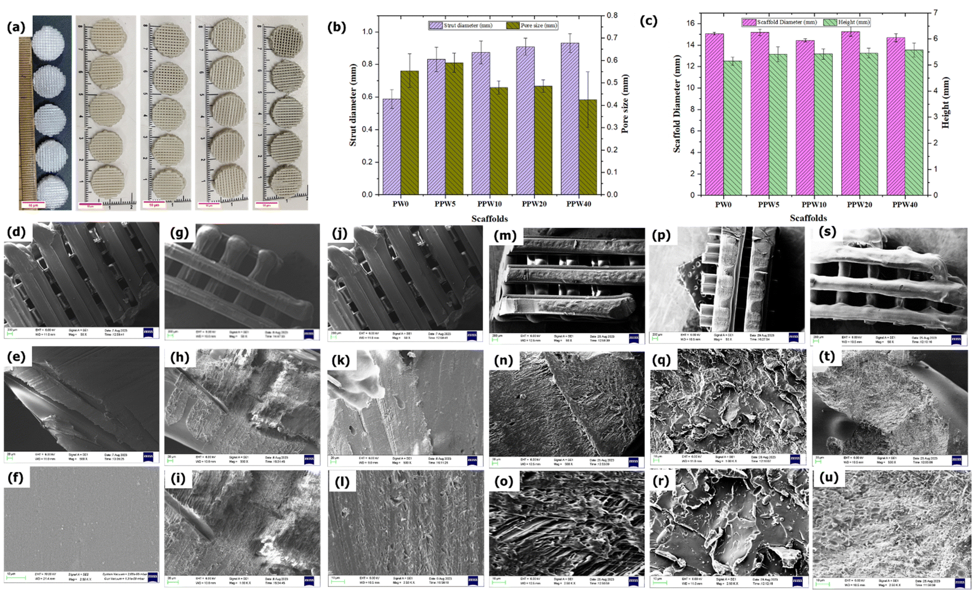 | ||
| Fig. 1 (a) 3D printed scaffolds. (b) Graph showing the measure value of strut size and pore size of scaffolds in mm. (c) Graph showing the measure value of outer diameter and height of scaffolds in mm. (d–f) SEM image of PLA scaffolds. (g)–(i) PLA–PCL scaffolds. (j)–(l) PPW5 composite scaffolds. (m)–(o) PPW10 composite scaffolds. (p)–(r) PPW20 composite scaffolds. (s)–(u) PPW40 composite scaffolds. | ||
4.2. Morphological analysis
The SEM image of composite scaffolds from the top surfaces at three zoom levels is presented in Fig. 1d–u. The SEM image of the PLA scaffold revealed an almost smooth surface with no visible attached particles on its surface, indicating that the process involved in processing the filament was free from any contamination. The morphology of the PLA/PCL biocomposite reveals a typical immiscible surface, i.e., a clear interface is visible between PLA and PCL as a continuous sea-island structure (Fig. 1g–i). A similar observation has been made by Urquijo et al., where the SEM image revealed that the PLA/PCL blend is immiscible.50 The PCL phase within the PLA matrix, up to a certain limit, increases the interfacial area and improves the overall stress transfer on the PLA–PCL system. The good adhesion between PLA and PCL makes the interface more resistant to applied load. The SEM image of the strand surface (Fig. 1g–u) displayed a perfect layer interfusion among all groups of scaffolds without any visible voids or defects, indicating an excellent printability of the composite filament. The dual method employed here for mixing the three phases, i.e., stirring during the solvent casting method and extrusion of the shredded pellet through a single screw wire extrusion machine, ensures uniform dispersion of fillers in the matrix. This was further confirmed by the SEM image showing no agglomeration of the filler in the matrix even at higher filler loading (40 wt%). The method adopted in this study for composite blending employed only one heat cycle, unlike other melt mixing methods, where the filament is extruded twice through the extruder to ensure uniform dispersion of fillers into the matrix. PLA is very sensitive to reprocessing cycles, and with each heat cycle the properties of PLA deteriorate.44 A study by Aguero et al. revealed that PLA suffers a slight degradation of properties after one or two reprocessing cycles (extrusion through extrusion molding), whereas the performance impairment becomes significant after the fourth reprocessing cycle.444.3. MFI and filament evaluation
The printability of the produced composite filaments through the FFF printer was determined by measuring the flowability and dimensional stability of the composite filament through rheological and thermal expansion coefficient studies. A pilot experiment was conducted to ascertain the feasibility of producing composite feedstock with high ceramic content through MFI measurement as an alternative measure of comparing the viscosity of the composite blends. The incorporation into the PLA–PCL matrix resulted in a decreased flow rate of the mixture compared to pure PLA (Fig. 2a). The MFI values decreased gradually as the content of WP increased in triphasic composites, while they are still inferior to the MFI value of pure PLA, which is deemed suitable for FFF-based 3D printing.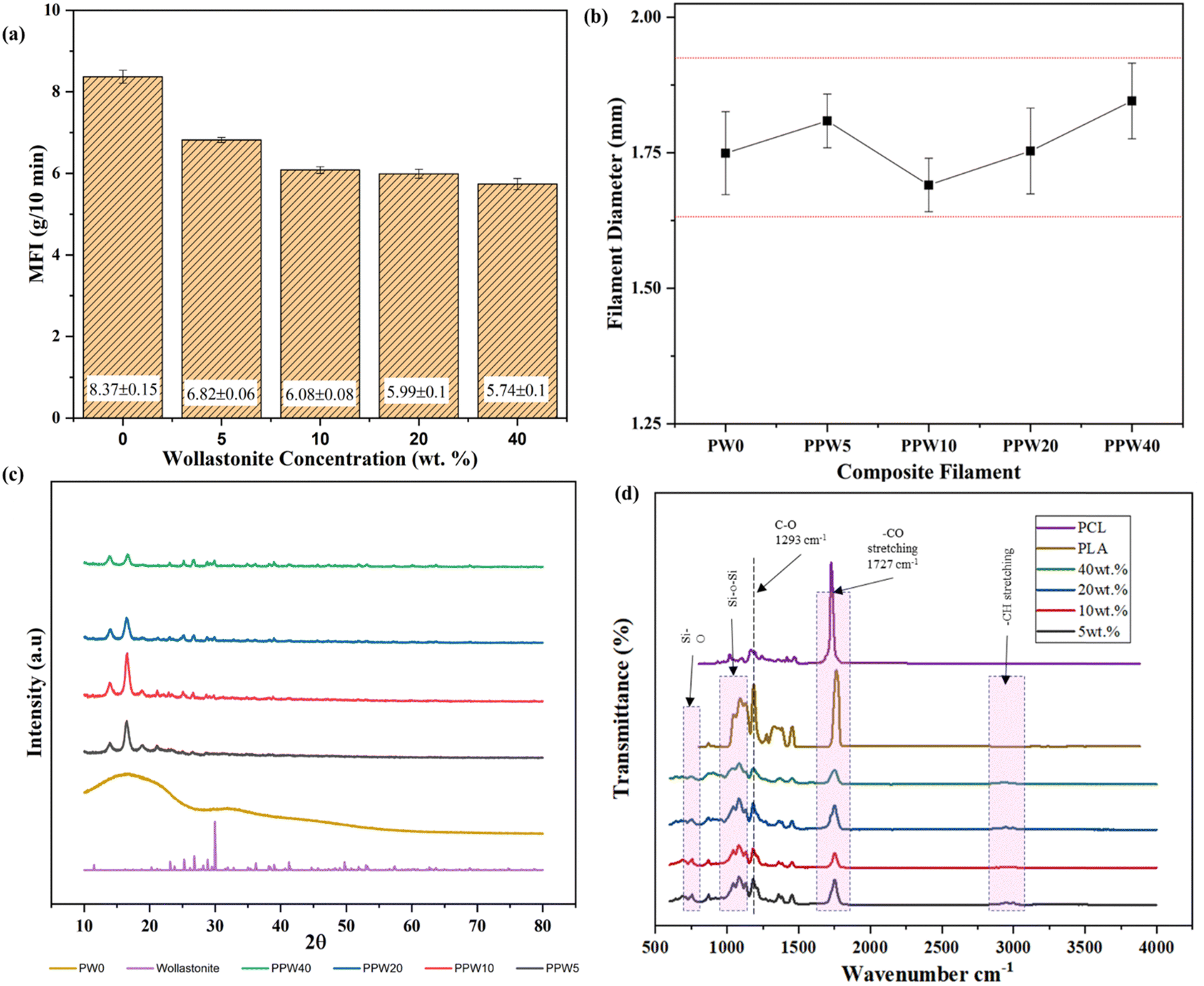 | ||
| Fig. 2 (a) MFI behaviour of composites as a function of wt% of WPs. (b) Filament diameter variation as a function of wt% of WPs. (c) XRD pattern of triphasic scaffolds with different weight ratios of wollastonite. (d) FTIR spectra of PLA, PCL, and WP reinforced composite scaffolds. | ||
This was mainly attributed to the poor flow properties of the material and its aggregation induced by the inclusion of WP, resulting in increased viscosity of the material. The MFI of PPW40 was reduced to 6 g/10 min from 8.5 g/10 min for pure PLA. The MFI reduced linearly with the addition of WPs, indicating confinement of polymer chain motions caused by the inclusion of WP. Similar results were reported by Razali et al., where the incorporation of ceramic particles reduced the MFI of the composite material.51 The reduction in MFI improved the processability of filament extrusion; however, at higher ceramic content (40 wt%), several difficulties, such as frequent filament breakage, were experienced. This was mainly due to the increased stiffness of WP reinforced composites.
A pilot bending test was initially performed on the thin sheet of composite materials to evaluate its processability through the FFF process. The thin sheet was manually bent at >45° to ascertain its brittleness (Fig. S1, ESI†). The result revealed that beyond 40 wt% of WP, the resulting composite sheets were too brittle to be processed into a filament form (Fig. S1a–f, ESI†). To overcome the issue of processability at higher ceramic content, PCL was introduced as a soft phase during the pilot study. Fig. 2b shows the variation in the diameter of the filament obtained through the extrusion process, having a diameter of ∼1.72 mm. The filament with a diameter of 1.60–1.90 mm is appropriate for an FFF-based 3D printer with a hot extruder and 0.4 mm–0.3 mm of nozzle output. As shown in Fig. 2b, the diameter of the produced composite filament is within the acceptable deviation (1.60–1.90 mm), making it suitable for FFF 3D printing. The deviation in filament diameter was more pronounced for PPW20 and PPW40 specimens, probably due to the reduced viscosity, change in the packaging density of the polymer melt, and the agglomeration of WP at higher content.
4.4. XRD
The X-ray diffractogram of wollastonite particles and the triphasic composite scaffolds with varying wollastonite content is depicted in Fig. 2c. The diffraction pattern of pure PLA has no sharp peaks, but instead a broad hump positioned between 2θ = 10° and 40°. The absence of a crystalline peak indicates that PLA has a more amorphous region. The sharp peak in the XRD pattern of wollastonite powder at 21.6° and 29.87° indicates its excellent crystallinity. A similar sharp peak could be observed in the X-ray diffractogram of composite scaffolds, and no other phase was observed. No such sharp characteristic peak was observed in the case of the pristine PLA scaffold (PW0), indicating the absence of a wollastonite phase. The two strong peaks roughly at 2θ = 21.4° and 23.8° correspond to the presence of semicrystalline PCL, arising from the diffraction of lattice planes (110 and 200), respectively. The presence of wollastonite and PCL was evident from the characteristic peak in the triphasic composite scaffolds. The addition of wollastonite improved the crystallinity of the resulting composite scaffolds. Improved crystallinity positively impacted the mechanical strength of the scaffold, as evident from the increased compressive strength (results discussed in the later section).4.5. FTIR analysis
FTIR spectroscopy can provide structural information on composites in terms of chemical interactions. FTIR spectroscopy is a technique that is sensitive to the asymmetrical vibrational modes of functional groups. PLA has a chemical formula of (C3H4O2)n, while PCL has a chemical formula of (C6H10O2)n; the CH bond and CO double bonds are attributed to the characteristic peaks of PLA and PCL. The FTIR spectral analysis was carried out with PLA–PCL–WP scaffolds to confirm the functional groups present in the resulting composite scaffolds. Fig. 2d depicts the FTIR spectrum of the PLA–PCL–WP composite scaffold. The presence of PLA in the composite blend was confirmed by an intense C![[double bond, length as m-dash]](https://www.rsc.org/images/entities/char_e001.gif) O carbonyl stretch band peak ranging from 1749 to 1751 cm−1, whereas symmetric stretching vibration corresponding to –CH3 groups at 2847–2936 cm−1 and asymmetric stretching of –CH3 ranging from 2959 to 2997 cm−1. The band observed at 1357–1376 cm−1 was associated with the symmetric bending vibration of –CH3, while vibration ranging from 1451 to 1466 cm−1 corresponded to asymmetric bending of –CH3. The spectrum for PCL shows several bands corresponding to the CH2 symmetric stretch at 3192 cm−1, CH2 asymmetric stretch at 3065 cm−1, carbonyl stretch at 1726 cm−1, and C–O stretch at around 1166 cm−1. There is no significant shift in the peaks of PLA and PCL in the triphasic PLA–PCL–WP composite scaffold spectrum, indicating little interaction between PLA and PCL in the blend. A similar observation was found in the literature, which suggests that both PLA and PCL are immiscible.52
O carbonyl stretch band peak ranging from 1749 to 1751 cm−1, whereas symmetric stretching vibration corresponding to –CH3 groups at 2847–2936 cm−1 and asymmetric stretching of –CH3 ranging from 2959 to 2997 cm−1. The band observed at 1357–1376 cm−1 was associated with the symmetric bending vibration of –CH3, while vibration ranging from 1451 to 1466 cm−1 corresponded to asymmetric bending of –CH3. The spectrum for PCL shows several bands corresponding to the CH2 symmetric stretch at 3192 cm−1, CH2 asymmetric stretch at 3065 cm−1, carbonyl stretch at 1726 cm−1, and C–O stretch at around 1166 cm−1. There is no significant shift in the peaks of PLA and PCL in the triphasic PLA–PCL–WP composite scaffold spectrum, indicating little interaction between PLA and PCL in the blend. A similar observation was found in the literature, which suggests that both PLA and PCL are immiscible.52
Moreover, the peak thermal degradation temperature of PLA and PCL is around 290° and 396 °C, respectively. Therefore, no chemical transformation was observed in the FTIR spectra. A peak at 564, 894, and 1020 cm−1 is associated with wollastonite particles.35 The characteristic absorption bands for the vibrational bending mode of Si–O–Si, between 1077 and 1081 cm−1, and the vibrational stretching mode of Si–O, between 862 and 894 cm−1, indicate the presence of wollastonite in the composite. By comparing these bands with the PLA/PCL/wollastonite spectrum, some shifts in the peak position were noticeable. This could be attributed to the chemical interaction between PLA–PCL and wollastonite particles. Moreover, FTIR spectra of all the groups of scaffolds exhibited very similar peaks of PLA and PCL, meaning that no polymer degradation was observed during the processing step.
This is more evident from the fact that the peak observed near 1727 cm−1 is mainly observed after the processing of the material, which is attributed to the carbonyl group (–CO). Therefore, the proposed two-stage processing route can produce high ceramic-loaded triphasic composite scaffolds.
4.6. Thermal stability
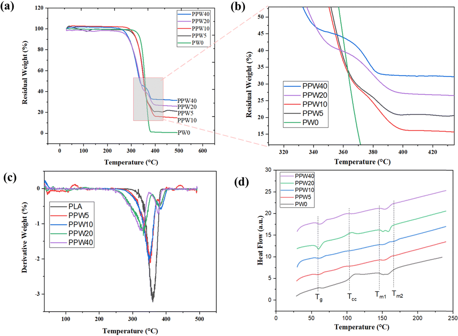 | ||
| Fig. 3 (a) TGA curve (b) enlarged section of TGA thermograms indicating the two-step degradation behaviour of PLA–PCL–WP composites. (c) Normalized derivative (DTG) of weight loss of the composite scaffolds for better visualization of the degradation step. (d) DSC thermograph of triphasic scaffolds. | ||
| Materials | T i (°C) | T p1 (°C) | T p2 (°C) | W end (%) |
|---|---|---|---|---|
| PW0 | 338.78 | 356.8 | — | 98.66 |
| PPW5 | 326.88 | 353.21 | 381.39 | 77.95 |
| PPW10 | 323.73 | 347.75 | 384.47 | 85.56 |
| PPW20 | 296.12 | 331.18 | 379.82 | 72.03 |
| PPW40 | 286.79 | 326.38 | 378.09 | 79.15 |
The glass transition temperature is a very complex phenomenon due to several factors including polymer chain flexibility, intermolecular interaction, and molecular weight of the materials. The glass transition temperature (Tg), crystallization temperature (Tc), and melting temperature (Tmi and Tmend) are summarised in Table 5. The result suggested that there is a decrease in the Tg of composite scaffolds as compared to PLA scaffolds.
| Materials | Thermal characteristics | |||
|---|---|---|---|---|
| T g (°C) | T c (°C) | T mi (°C) | T mend (°C) | |
| PW0 | 58.75 | 95.27 | 142.60 | 169.54 |
| PPW5 | 55.14 | 82.38 | 140.82 | 162.13 |
| PPW10 | 55.04 | 84.33 | 141.04 | 173.56 |
| PPW20 | 56.29 | 93.10 | 139.95 | 166.39 |
| PPW40 | 56.11 | 82.13 | 138.44 | 166.29 |
As PCL is more flexible than PLA, including PCL into the PLA matrix leads to a slight decrease in Tg from 58.75 °C for PLA to 56.11° for the PPW40 composite scaffold due to its plasticizing effect.54 However, no particular trend of variation in Tg was detected, regardless of the presence of wollastonite particles. PLA and the PLA–PCL–WP composite exhibited cold crystallization, a phenomenon verified in the literature.55 The arrangement of the amorphous region into a more arranged crystalline phase causes the release of energy which is reflected as an endothermic peak during DSC characterization. The addition of PCL initiates the movement of the polymeric chain during heating, resulting in accelerated crystallization of the composites. This phenomenon is reflected by an early onset of crystallization temperature from 99 °C for PLA to 82.13 °C for PPW40. The effect of crystallization positively affects the mechanical properties due to a more packed structure in the resulting composites.
Additionally, the anchoring effect of the wollastonite particles is likely to act as a nucleating agent. According to Liang et al., wollastonite particles act as a heterogeneous nucleus and promote the PLA chain crystallization at lower temperature.56 This finding reflects a better reinforcing effect of the polymer and filler matrix. Except for PLA, all the composite scaffolds exhibit two endothermic peaks: a low-temperature peak corresponding to the melting of PCL and a high-temperature peak corresponding to the melting of PLA. The addition of wollastonite did not affect the thermal behavior of the composite scaffold, while it enhanced the crystallinity of the pristine PLA. The enhanced crystallinity improves the mechanical strength of composite scaffolds.
4.7. Mechanical characterization
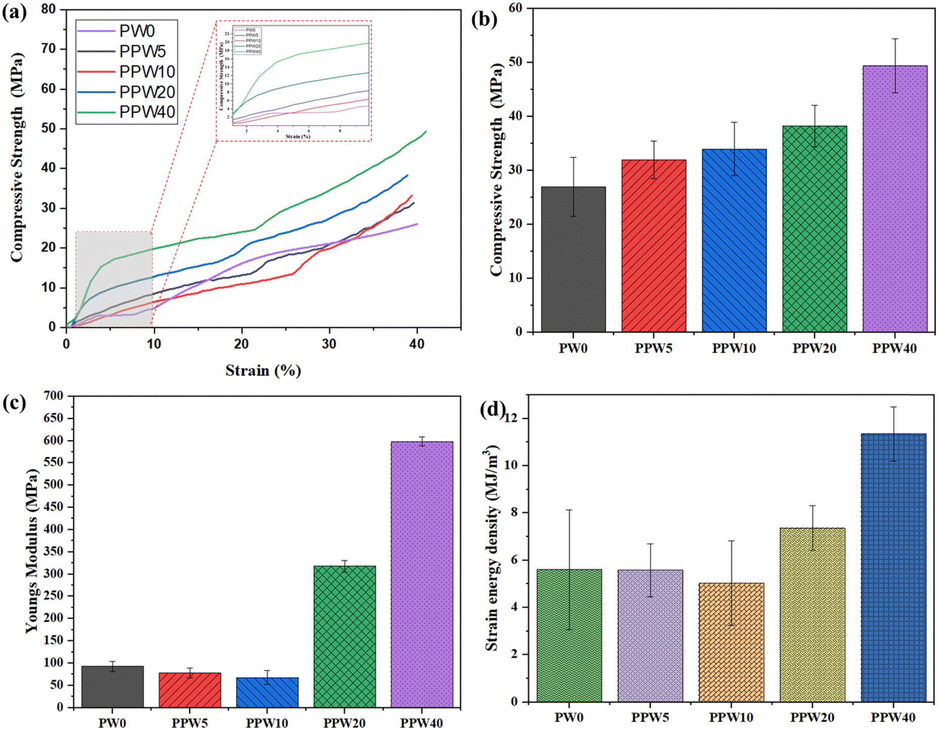 | ||
| Fig. 4 Compression test of composite scaffolds. (a) Stress–strain curve of PLA and WP reinforced PLA/PCL scaffolds. (b) Compressive strength of scaffolds. (c) Young's modulus of scaffolds. (d) Strain energy density of scaffolds. | ||
The inset of Fig. 4a shows that with an increase in WP, the load-bearing capacity of the scaffold increases, resulting in an increased modulus of the scaffold. The pure PLA scaffold exhibited a Young's modulus of 91.7 MPa, which increased to 597.84 MPa in the case of the PPW40 scaffold (Fig. 4c). Both the compressive strength and the modulus follow the order of PLA > PPW5 > PPW10 > PPW20 > PPW40, indicating a significant strengthening effect of wollastonite particles. The incorporation of micro-acicular wollastonite improved the compressive strength of the composite scaffolds and provided better resistance toward compressive load. The wollastonite particles got aligned in the flow direction of extrusion during the 3D printing of the scaffold. This property could be ascribed to the high modulus of the wollastonite particles. However, at a higher content of WP (40 wt%), the resulting composite was too brittle which inhibited its printability through the FFF process. Therefore, to incorporate toughness and improve the crack-bridging effect, PCL was included in the PLA–WP matrix. Many previous works suggest the inclusion of PCL, a soft phase, with a ceramic phase to improve the load-bearing capacity of ceramic, thus preventing the sudden failure of the material.9,55,57 The ability of a material to absorb mechanical energy up to the point of failure is termed toughness and is represented by the area under the stress–strain curve. Better toughness indicates that the material is less likely to suffer a brittle component fracture. It is of paramount importance while designing the implants to avoid sudden failure. The toughening effect of PCL incorporation into the PLA matrix was quantified by calculating the area under the experimental stress–strain curve for all five groups of scaffolds, as shown in Fig. 4d.
The toughening effect of PCL was significant in the case of the PPW40 scaffold, enabling it to resist load without any crack propagation, even at high ceramic content. Moreover, the compressive strength of the scaffold was also evaluated after an incubation period of 28 days to investigate the effect of WP on mechanical strength. Fig. 5a represents the compressive strength of PLA and composite scaffolds at the end of 28 days of incubation. The result reveals that due to the absence of WP, there is no reduction in the compressive strength of the PLA scaffold. Interestingly, the compressive strength of the PLA scaffold showed an increased value of ∼35 MPa compared to the day one strength of ∼26 MPa. The increased strength could be due to the deposition of a salt layer covering the pores of the scaffold, thus increasing the load-resisting capacity of the scaffold. The scaffold with WP exhibited reduced compressive strength, due to dissolution of Ca and Si ions in the SBF medium. The compressive strength of the PLA–PCL–WP scaffold remained in the region of 18 MPa to 35 MPa and followed a decreasing trend with increasing WP content. The reduction in strength was significant in the case of the PPW40 scaffold, which amounted to almost 66.9%, followed by 51.73% for PPW20, 46.97% for PPW10, and 1.31% for PPW5 scaffolds. Despite the reduction in compressive strength, all the scaffolds maintained their structural integrity, indicating their potential application for bone regeneration studies.
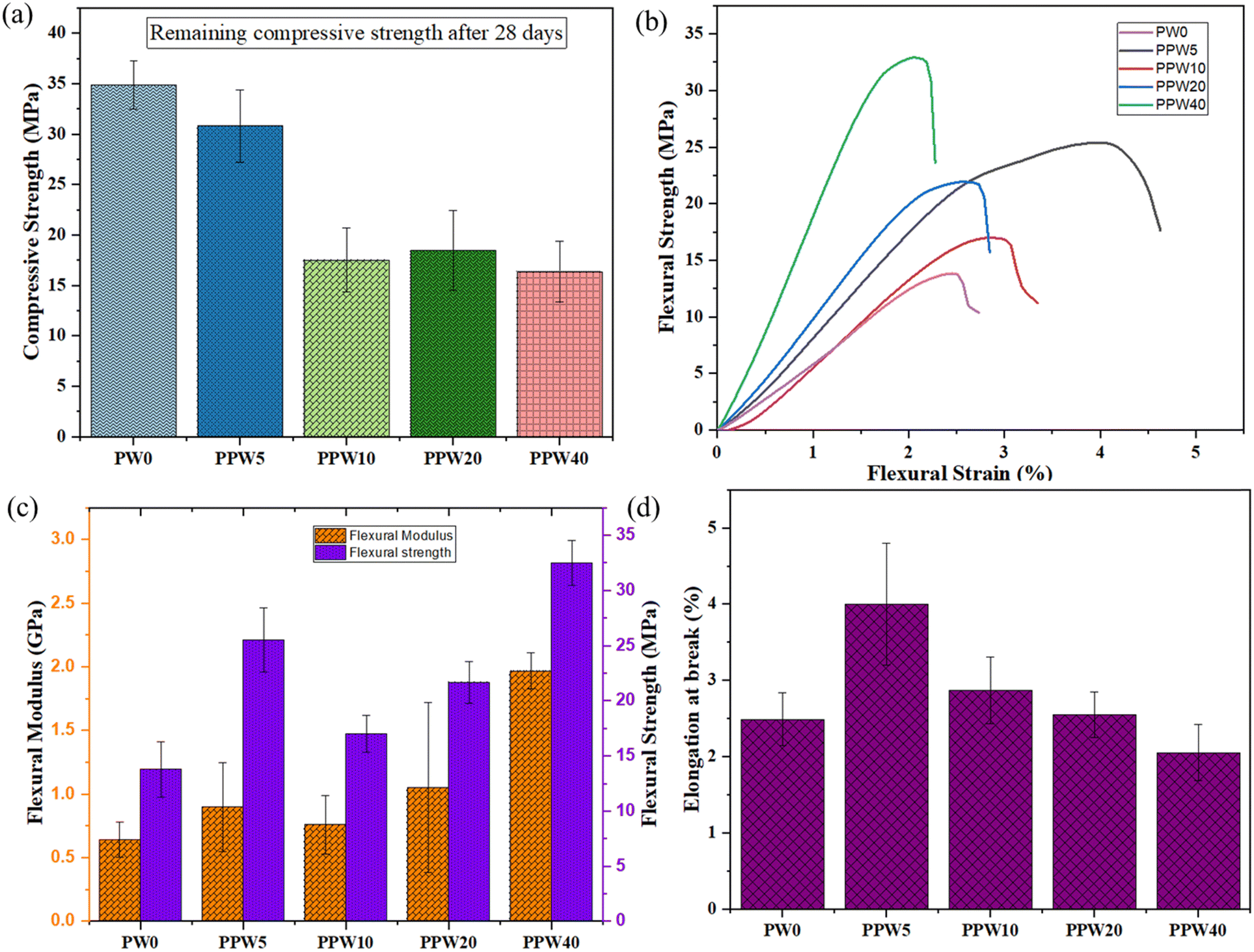 | ||
| Fig. 5 (a) Stress–strain curve of PLA and WP reinforced PLA/PCL scaffolds incubated in SBF for 28 days. (b) Stress–strain curve for the flexural test of a rectangular specimen. (c) Graph showing flexural modulus and flexural strength. (d) Graph showing elongation at break. | ||
4.8. In vitro degradation
The degradation behavior of all four groups of scaffolds is presented in Fig. 6a. The weight loss in all the groups of scaffolds increased with the incubation time. The weight loss in PPW40 was significantly higher (∼20%), followed by ∼12%, ∼6%, and ∼4% of their initial weight for PPW20, PPW10, and PPW5 scaffolds at the end of 28 days. In contrast, the PW0 (i.e., PLA) scaffold did not exhibit any significant change in weight loss during the entire incubation period, and the weight loss was only ∼0.5%. The fast dissolution of silica from the wollastonite into the SBF medium contributed to maximum weight loss in the PPW40 scaffold. Similarly, degradation behavior was reported by Wei et al., who studied the degradation behavior of a WP reinforced PCL composite for a period of 12 weeks.36 The fast dissolution was followed by the formation of apatite layers on the scaffold, reflected by an increased pH value of ∼7.5, as shown in Fig. 6b. This result suggests that the WP exhibits much faster degradation due to its needle-shaped micro-structure. The pH values of all the groups of scaffolds were maintained at 7.4 on day 1 of incubation. The pH values for the PLA scaffold decreased with the incubation period inducing an acidic degradation medium, an unwanted property for BTE application. In contrast, the pH values of the WP loaded scaffold showed a slight increase in the first week of incubation, which then increased rapidly at the end of the incubation period. The WP induced alkaline degradation of the scaffold is in the range of 7.45–7.6, thus inhibiting the acidic effect of pure PLA scaffolds. The inclusion of WP is therefore beneficial in eliminating the acidic degradation of the polymer, which is supposed to provide a favorable environmental condition for cell–material interaction.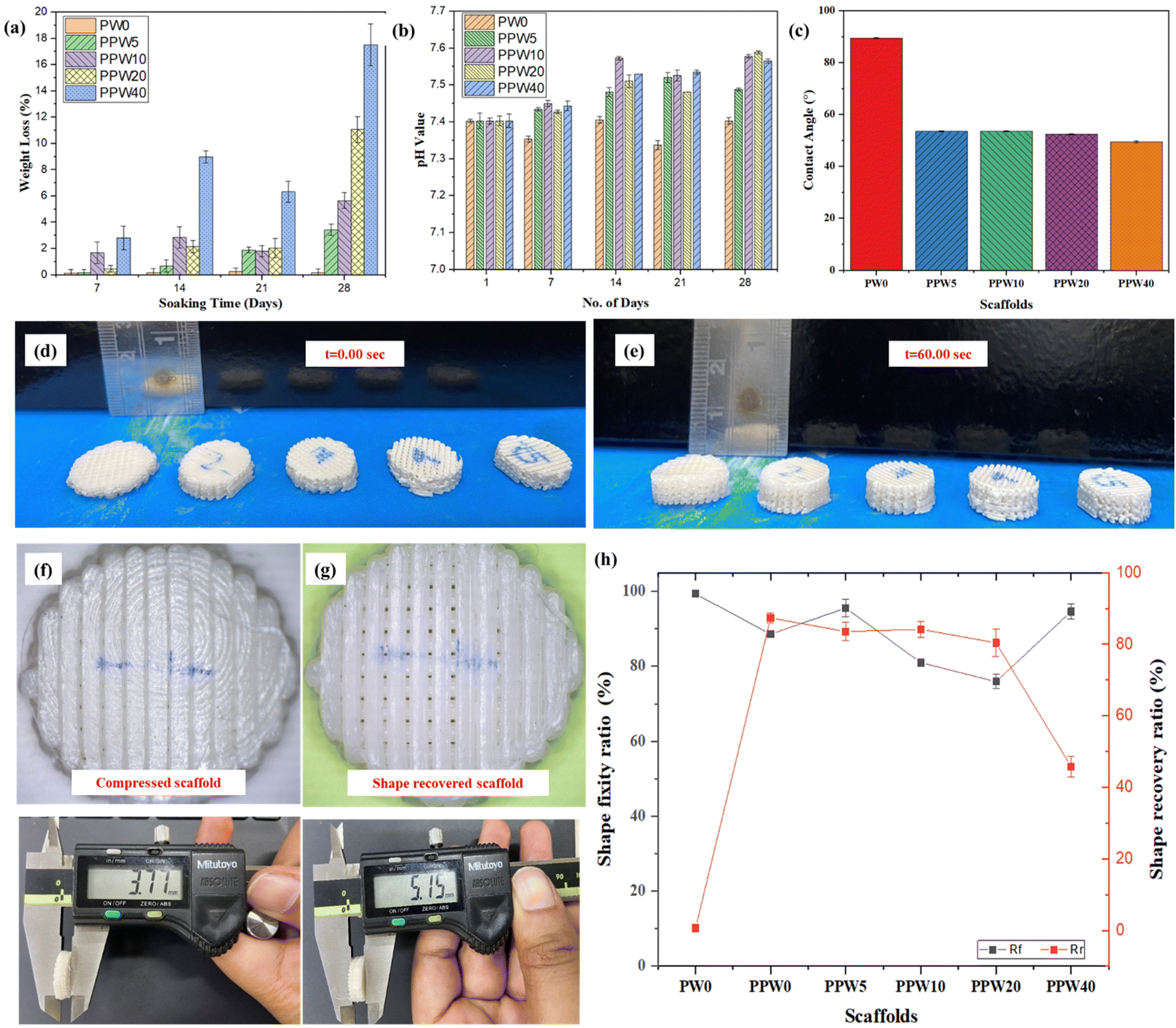 | ||
| Fig. 6 (a) pH change of the PLA–PCL–WP scaffold over a period of 28 days. (b) Weight loss profile of the PLA–PCL–WP scaffold over a period of 28 days. (c) Water contact angle of the triphasic composite scaffolds with different weight ratios of wollastonite. (d) Compressed scaffolds at t = 0.00 s, before heating of the bed. (e) Shape regained scaffolds at t = 60.00 s, post heating of the bed. (f) Compressed scaffold with closed pores. (g) Shape regained scaffold with open, visible pores. (h) Graph showing shape fixity ratio and shape recovery ratio. | ||
4.9. Water contact angle
The hydrophilicity of a material is very crucial in determining its suitability for use in biomedical implants. Increased hydrophilicity of an implant improves the adhesion between the implant and the bone, helping in faster regeneration of the damaged tissues in vivo. The contact angle analysis result of the composite scaffolds with and without wollastonite particles is presented in Fig. 6c.The pure PLA scaffold exhibited the maximum water contact angle (89° ± 2.1), indicating the lowest hydrophilicity. As per the literature survey, PLA is a nonpolar polymer having low surface energy, which hinders its wettability.55 The addition of wollastonite particles into PLA increases the affinity of composite scaffolds towards water. The PLA–PCL–WP composite scaffolds exhibited WCA in the range of 49–54° with the WCA reduced to 49.61° at 40 wt% of wollastonite loading. Adding wollastonite reduced the composite's WCA, indicating improved wettability. The results suggest that the developed composite scaffolds have improved surface chemistry with a change in contact angle from 89° ± 2.1 to 68° ± 2.3. However, there was no significant difference in the WCA of composite scaffolds at different concentrations of WP. As per the literature, a hydrophilic surface with a WCA of 60–80° provides the optimum condition for cell culture; however, an excessive hydrophilic surface may cause undesirable platelet adhesion, causing blood clotting, which may hinder the long-term vascularization property of a scaffold.58,59
4.10. Shape memory behavior
The shape recovery properties of the triphasic scaffolds were investigated by placing the scaffolds on the heated bed plate at a temperature of 60 °C. Fig. 6d shows the image of the compressed scaffold with closed pores due to densification during compression. After exposing to a heated plate (T > Tm), all the scaffolds exhibited shape recovery properties, and pores were clearly visible as the scaffolds regained their original shape. The variation in height was recorded to quantify the shape memory behavior of composite scaffolds. The pure PLA scaffold (PW0) exhibited a shape fixity ratio (Rf) of ∼99.4% with a shape recovery ratio (Rr) of ∼0.6% due to the poor thermal effect. Interestingly, the addition of PCL reduced the shape fixity ratio (Rf) and increased the Rr of the scaffolds. However, the addition of WP reduced the Rr of the scaffold and the value of Rr decreased with increasing WP content. For instance, the Rf and Rr of the PW0 scaffold containing 0 wt% of WP were ∼88.6% and 87.3%, respectively. Similarly, the Rf and Rr of PPW5, PPW10, PPW20 and PPW40 were recorded as ∼95.6% and ∼83.5%, ∼81.6% and ∼84.2%, ∼75.9% and ∼80.4%, and ∼94.6% and ∼45.8% respectively. The shape recovery ratio was least in the case of the PPW40 scaffold, indicating that WP inhibited the shape recovery property of the scaffold, primarily due to the highly anchored polymeric chain. The incorporation of PCL reduced the glass transition temperature of composite scaffolds, and the PCL phase acted as the switching segment in the triphasic composite scaffolds, resulting in shape memory behavior.60–62 PLA and WP acted as the fixed hard phase for the shape fixity, while PCL acted as the soft reversible phase for shape recovery.4.11. Protein adsorption study
The adsorption of protein to the scaffold is a major milestone in integrating artificial implants with the host tissue. Higher protein adsorption can elicit adverse responses from the host tissue, such as coagulation of blood cells and immune system activation. Therefore, moderate surface hydrophobicity is desirable to control the hydration of the implant. Blood serum proteins are most abundant and interactive; bovine serum albumin (BSA) was used as a model protein to evaluate the protein adsorption on WP incorporated composite scaffolds. Significantly higher BSA adsorption (Fig. 7a) was observed on PLA (104.1 μg mL−1) compared to PPW5 (56.53 μg mL−1), PPW10 (45 μg mL−1), PPW20 (43.07 μg mL−1), and PPW40 (20.76 μg mL−1). The results demonstrated that blending PLA–PCL with WP reduced the protein adsorption on the PLA scaffold. These results are in corroboration with the contact angle study where increasing WP demonstrated lowering of the contact angle. Hydrophilic surfaces are known for non-fouling due to dynamic adsorption and limited spreading of proteins on implants.63–65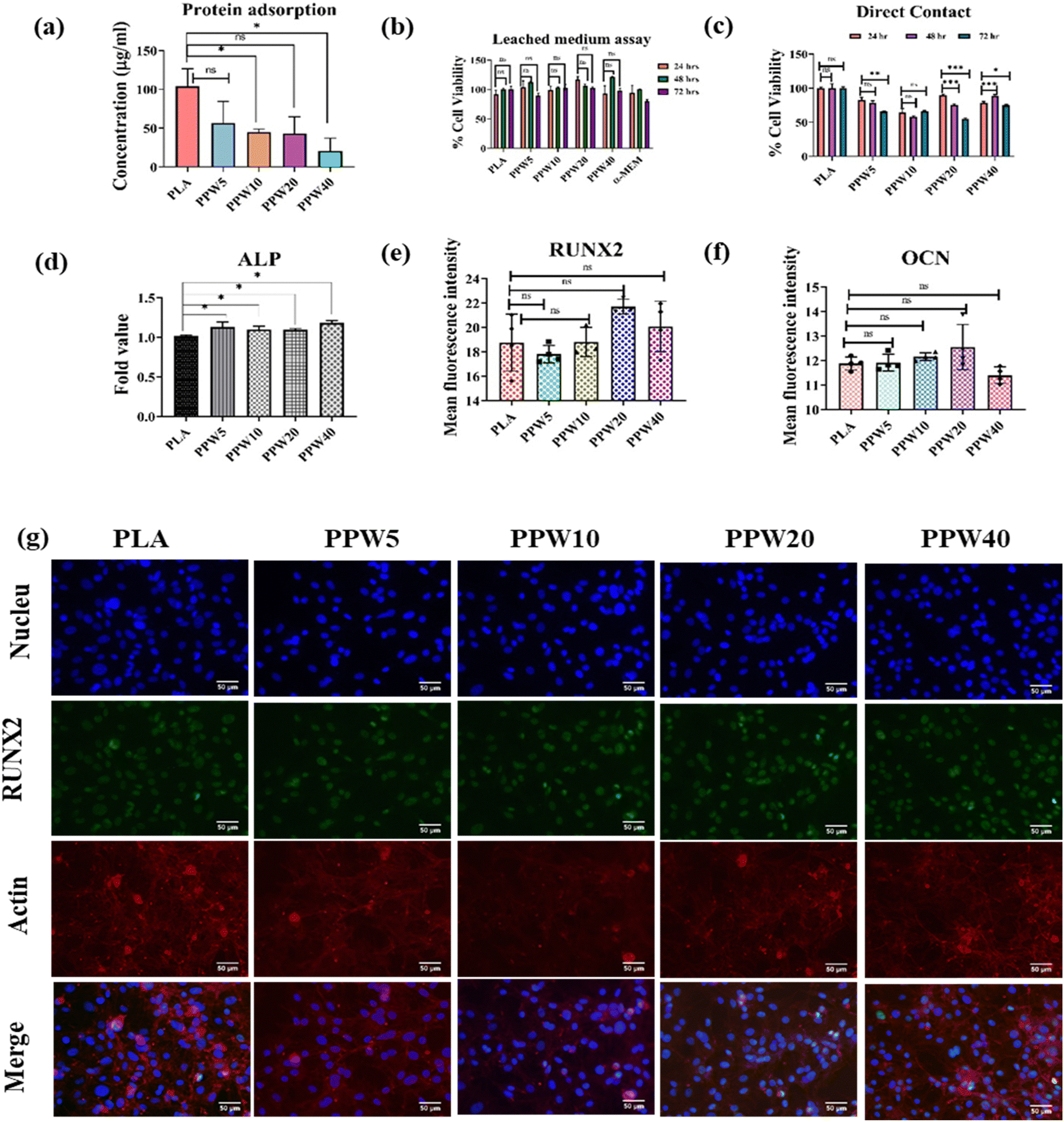 | ||
| Fig. 7 The biological characterization of PLA, PPW5, PPW10, PPW20, and PPW40. (a) Protein adsorption. The cell proliferation of MC3T3-E1 cells via (b) leached medium assay and (c) direct contact method. (d) ALP activity of MC3T3-E1 cells. Mean fluorescence intensity of the marker (e) RUNX2 and (f) OCN after ICC in MC3T3-E1 cells. (g) ICC showing the expression of RUNX2 in MC3T3-E1 cells after 7 days of culture (nucleus (DAPI), RUNX2 (green), actin (red phalloidin) and merge image). | ||
4.12. Biocompatibility studies
Long-term compatibility is critically important for any artificial implant, such as scaffolds. The compatibility of the scaffold is important for its biological application in the tissue engineering field. A hydrating scaffold can leach its constituents which could influence the cell adhesion to its surface, its integration with the host tissue, or growth of neighboring cells. Therefore, in the present study, the leached medium from the triphasic composite scaffolds was collected and used to determine its effect on the proliferation of MC3T3-E1 cells. No significant differences in cell proliferation were observed in all the scaffolds (24 h, 48 h, and 72 h) (Fig. 7b). The results indicated that the composite scaffold did not leach any substance affecting cell proliferation. The leached medium-treated cells were viable with respect to time (24 h, 48 h, and 72 h).In another study, MC3T3-E1 cells were directly cultured on PLA, PPW5, PPW10, PPW20, and PPW40 scaffolds and studied for their proliferation, as shown in Fig. 7c. Except for PPW40, all the WP incorporated scaffolds demonstrated a marginal decrease in cell proliferation from 24 to 48 h. At 72 hours, except for PPW20, the remaining scaffolds did not demonstrate any significant decrease in cell proliferation. Similarly, MC3T3-E1 cells were seeded on PLA, PPW5, PPW10, PPW20, and PPW40 3D printed scaffolds for cell viability/cell count analysis for a longer period. After 7 days of cell culture on the respective PLA–wollastonite scaffold, the cells were isolated and counted using a hemocytometer. The authors observed a higher cell count after 7 days as compared to the seeded density on day 1 (145000 cells per scaffold). A higher cell count was observed in all groups, i.e., PLA (17 × 105), PPW5 (17 × 105), PPW10 (17 × 105), PPW20 (11 × 105), and PPW40 (17.25 × 10⁵), at day 8 (Fig. S2, ESI†). In summary, none of the scaffolds demonstrated less than 50% cell viability, indicating their compatibility and growth-promoting behavior.
4.13. Osteogenic studies
The mineralization potential of the scaffolds was determined by alkaline phosphatase assay. MC3T3-E1 cells were seeded directly on PLA, PPW5, PPW10, PPW20, and PPW40 3D-printed scaffolds and allowed to grow for 7 days. After 7 days, ALP activity was determined.The results demonstrated that PPW5 (0.25-fold), PPW10 (0.12-fold), PPW20 (0.097-fold), and PPW40 (0.096-fold) showed higher ALP activity than PLA (Fig. 7d). A marginal increase in ALP activity was observed in all the scaffolds compared to PLA. Similarly, non-significant ALP expression was observed with a higher concentration of WPs in the indirect ALP assay until day 14 (Fig. S3, ESI†). A prolonged study would be desirable for observing the significant difference in osteogenic markers. However, the initial result indicates that the incorporation of WP has higher ALP activity signifying the higher mineralization potential. However, increasing the concentration of WP lowered the mineralization potential of the cells. This suggests that an increase in the concentration of WP lowered the mineralization potential of the MC3T3-E1 cells compared to PLA scaffolds. However, PPW5 and PPW10 favored the mineralization/differentiation of the MC3T3-E1 cells.
The Runt-related transcription factor (RUNX2) and osteocalcin (OCN) are important markers for bone mineralization.66 Their expression correlates with osteoblast differentiation. Therefore, RUNX2 and OCN were used to analyze the differentiation potential of the reinforced PLA/PCL scaffolds after 7 d of culture. RUNX2 expression was non-significant in all groups compared to the control PLA scaffold. We observed that the MFI of PLA (18.76), PPW5 (17.81), PPW10 (20.92), PPW20 (21.7) and PPW40 (20.08) was non-significant (Fig. 7e). Osteocalcin is a molecule produced by the osteoblast cells and it is a late osteogenic marker. Non-significant expression of OCN (Fig. 7f) was observed in PPW5 (11.91MFI), PPW10 (12.15 MFI), PPW20 (12.55) and PPW40 (11.40 MFI) compared to PLA (11.88 MFI) scaffolds as shown in Fig. S4 (ESI†) fluorescence images. The mean fluorescence intensity (MFI) of RUNX2 was also determined from the fluorescence images as shown in Fig. 7g. Overall, the study demonstrates that early mineralization in pre-osteoblast cells cultured in different WP incorporated composite scaffolds was similar to that in pure PLA scaffolds. This indicates that the incorporation of WP did not affect the bone mineralization potential of the porous scaffolds.
5. Summary and conclusion
In the present study, we prepared a triphasic composite scaffold through composite filament using a low-cost FFF 3D printer. The composite filament was initially produced following a two-step process to ensure homogeneous mixing and proper dispersion of WP in the PLA–PCL matrix. The prepared triphasic composite scaffolds were characterized by SEM, XRD, FTIR, compression, flexural, TGA, and DSC analysis. The FTIR spectrum revealed the presence of PLA, PCL, and WP in the prepared composite scaffolds. The wavenumber obtained for PLA and PCL during FTIR spectroscopy did not reveal any significant change, indicating the immiscibility of both the polymers and therefore PCL and PLA did not chemically interact at all in the triphasic blends. A similar behavior of the PLA/PCL blend is reported in previous studies.26 The homogeneous mixing of WP was confirmed by SEM imaging showing WP dispersed uniformly throughout the scaffolds. Further, the two distinct phases of PCL and PLA were also evident from the SEM images, as reported by many previous studies. The addition of WP did not affect the thermal properties of the scaffolds. However, adding PCL reduced the thermal stability due to its lower melting temperature. The onset of degradation temperature of the composite scaffold was reduced by ∼50° in the case of the PPW40 scaffold as compared to pure PLA scaffolds. Since WP is stable within this temperature range, the reduction in the degradation temperature is mainly attributed to the presence of PCL. Saravan et al. reported that the addition of WP into the PLA blend enhances the thermal stability and improves the crystallization of the resulting composite.67 The 3D printed composite scaffolds are mechanically stronger, and the incorporation of WP increased the compressive strength of the scaffold by almost 90% compared to pure PLA scaffolds. The PPW40 composite scaffold exhibited a significant increase in compressive strength (∼50 MPa), and the elastic modulus of PPW40 reached almost 600 MPa, which is much higher than that of pure PLA scaffold. The flexural strength was improved by ∼135% for the PPW40 scaffold. However, the elongation at break was marginally compromised (∼17%) due to high ceramic content making it brittle. The incorporation of PCL was beneficial in enhancing the flexural property of scaffolds at high ceramic loading, as it acted as a toughening agent for both brittle PLA and WP. At the same time, PCL acted as a softening phase to induce flexibility in the extremely hardened and brittle composite obtained at 40 wt% WP content in the composite. PCL, as a minor phase in the composite, improved the stress transfer and allowed the formation of stiffer bonds between the layers, contributing toward improved flexural properties of the scaffolds. The addition of WP improved the crystallinity of the composite scaffolds, as confirmed by the presence of sharp peaks in the XRD pattern, unlike the broad plateau seen in the diffraction pattern of pure PLA. The presence of silica and needle-shaped WP filler enhanced the crystallinity, thereby improving the mechanical properties of scaffolds. The incorporation of WP enhanced the in vitro degradation behaviour of the composite scaffold due to the dissolution of Ca and SiO2 in the SBF medium, resulting in a maximum weight loss of 20% in the case of the PPW40 scaffold over an incubation period of 28 days. The acidic degradation of pure PLA scaffolds negatively affects the biological responses during the bone healing process. Therefore, the addition of WP balanced the pH value of the SBF medium in the alkaline range of 7.5–7.7, making it suitable for BTE applications. The surface chemistry of scaffolds could be improved with the addition of WP and the change in the WCA was significant in the case of the PPW40 scaffold with a value of 52.34 ± 0.24°. The hydrophobic PLA scaffold turned hydrophilic, making it suitable for cell affinity. The 3D-printed scaffolds exhibited excellent shape recovery properties due to the addition of the PCL phase. The soft PCL phase acted as a switching segment while PLA and WP acted as a fixed hard phase, resulting in a scaffold with shape memory property. The shape recovery ratio lies in the 80–84% range for the scaffolds with up to 20 wt% of WP. These scaffolds were also studied for protein adsorption, cell proliferation, and bone mineralization potential. The incorporation of WP reduced the protein adsorption capacity of the PLA/PCL scaffold. Significantly higher BSA adsorption was observed on the pristine PLA (104.1 μg mL−1) scaffold as compared to WP reinforced PLA/PCL scaffolds. The biocompatibility test revealed that the scaffold did not leach any toxic substance and demonstrated good cell viability, indicating its biocompatibility and growth-promoting behavior. Moreover, the direct cell culture test revealed that except for the PPW40 scaffold, all the reinforced PLA/PCL scaffolds demonstrated a marginal decrease in cell proliferation from 24 h to 48 h. However, at 72 h, no decrease in cell proliferation was observed in all the groups of scaffolds except for PPW20 scaffolds. The cell count after 7 days as compared to the seeded cell density on day 1 (i.e., 145000 cells per scaffold) was significantly higher on all the scaffolds, i.e., PLA (17 × 105), PPW5 (17 × 105), PPW10 (17 × 105), PPW20 (11 × 105) and PPW40 (17.25 × 10⁵) at day 8. The osteogenic study of the triphasic composite scaffolds revealed that the ALP activity was significantly higher in WP reinforced PLA/PCL scaffolds, suggesting a lower mineralization potential of wollastonite particles for MC3T3-E1 cells. Interestingly, the PPW5 and PPW10 scaffolds favored the mineralization/differentiation of the MC3T3-E1 cells. In summary, the biological study demonstrates that early mineralization in pre-osteoblast cells cultured in different WP incorporated composite scaffolds was similar to that in PLA scaffolds.
Based on these results, we believe that the developed 3D-printed triphasic composite scaffolds hold great potential for BTE applications and other biomedical applications requiring shrinkable structures or tubing with improved mechanical strength.
Data availability
The authors confirm that the data supporting the findings of this study are available within the article and/or its ESI.†Conflicts of interest
The authors declare no conflict of interest in the publication of this article.Acknowledgements
This research was funded by a Start-up Research Grant (SRG/2019/001504) awarded to HSN and the Science and Engineering Research Board (SERB-TETRA) (TTT/2021/000120) awarded to RV from the Department of Science and Technology, the Government of India. The authors are grateful for the support from the Ministry of Human Resource Development, Government of India, for the Institute Teaching Assistantship to Mr Mohammad Aftab Alam Ansari and CSIR for providing the SRF fellowship to Miss Pooja Makwana for conducting this research work as a part of his/her PhD thesis.References
- J. R. Perez, D. Kouroupis, D. J. Li, T. M. Best, L. Kaplan and D. Correa, Front. Bioeng. Biotechnol., 2018, 6, 1–23 CrossRef PubMed.
- D. Zhang, O. J. George, K. M. Petersen, A. C. Jimenez-Vergara, M. S. Hahn and M. A. Grunlan, Acta Biomater., 2014, 10, 4597–4605 CrossRef CAS PubMed.
- G. Pertici, F. Carinci, G. Carusi, D. Epistatus, T. Villa, F. Crivelli, F. Rossi and G. Perale, J. Biol. Regul. Homeostatic Agents, 2015, 29, 136 CAS.
- A. P. Rickel, X. Deng, D. Engebretson and Z. Hong, Mater. Sci. Eng., C, 2021, 129, 112373 CrossRef CAS PubMed.
- Z. Maan, N. Z. Masri and S. M. Willerth, Biomolecules, 2022, 12(1) DOI:10.3390/biom12010141.
- R. Pemmada, V. S. Telang, M. Dash, J. L. Charles Richard, P. Tandon, S. Ramakrishna and H. S. Nanda, Tissue Eng., 2022, 415–430 Search PubMed.
- M. A. A. Ansari, A. A. Golebiowska, M. Dash, P. Kumar, P. K. Jain, S. P. Nukavarapu, S. Ramakrishna and H. S. Nanda, Biomater. Sci., 2022, 10(11), 2789–2816 RSC.
- G. L. Koons, M. Diba and A. G. Mikos, Nat. Rev. Mater., 2020, 5, 584–603 CrossRef CAS.
- S. Eqtesadi, A. Motealleh, A. Pajares, F. Guiberteau and P. Miranda, J. Non-Cryst. Solids, 2016, 432, 111–119 CrossRef CAS.
- C. Murphy and K. C. R. Kolan, 2016 International Solid Freeform Fabrication Symposium, 2016, pp. 1718–1731.
- T. Albrektsson and C. J. ohansson, Eur. Spine J., 2001, 10, S96–S101 CrossRef PubMed.
- M. A. A. Ansari, P. Makwana, R. Vasita, P. K. Jain and H. S. Nanda, Ceram. Int., 2023, 49(23), 37768–37781 CrossRef CAS.
- L. G. Blok, M. L. Longana, H. Yu and B. K. S. Woods, Addit. Manuf., 2018, 22, 176–186 CAS.
- M. A. A. Ansari, P. K. Jain and H. S. Nanda, J. Biomater. Sci., Polym. Ed., 2023, 0, 1–22 Search PubMed.
- M. Pluta, M. Murariu, A. Da Silva Ferreira, M. Alexandre, A. Galeski and P. Dubois, J. Polym. Sci., Part B: Polym. Phys., 2007, 45(19), 2770–2780 CrossRef CAS.
- S. Bose, M. Roy and A. Bandyopadhyay, Trends Biotechnol., 2012, 30, 546–554 CrossRef CAS PubMed.
- I. Fortelny, A. Ujcic, L. Fambri and M. Slouf, Front. Mater., 2019, 6, 1–13 CrossRef.
- L. Fambri and C. Migliaresi, Poly (Lactic Acid) Synth. Struct. Prop. Process. Appl. End Life, 2022, 135–151 CAS.
- G. F. da Fonseca, S. de, O. M. Avelino, D. de C. R. Mello, R. F. do Prado, T. M. B. Campos, L. M. R. de Vasconcellos, E. de Sousa Trichês and A. L. S. Borges, J. Mater. Sci.: Mater. Med., 2020, 31, 1–10 CrossRef PubMed.
- K. Ragaert, I. De Baere, J. Degrieck and L. Cardon, 6th Polym. Mould Innov. Int. Conf. Proc., 2014, 339–344.
- L. Aliotta, P. Cinelli, M. B. Coltelli and A. Lazzeri, Eur. Polym. J., 2019, 113, 78–88 CrossRef CAS.
- Z. Jiang, K. Zhang, L. Du, Z. Cheng, T. Zhang, J. Ding, W. Li, B. Xu and M. Zhu, Mater. Sci. Eng., C, 2021, 126, 112178 CrossRef CAS PubMed.
- S. Ma, Z. Jiang, M. Wang, L. Zhang, Y. Liang, Z. Zhang, L. Ren and L. Ren, Bio-Design Manuf., 2021, 4, 867–878 CrossRef CAS.
- Y. Wang, Y. Wang, Q. Wei, J. Zhang, M. Lei, M. Li and D. Li, J. Polym. Res., 2021, 28, 1–13 CrossRef CAS.
- S. Hassanajili, A. Karami-Pour, A. Oryan and T. Talaei-Khozani, Mater. Sci. Eng., C, 2019, 104, 109960 CrossRef PubMed.
- S. Solechan, A. Suprihanto, S. A. Widyanto, J. Triyono, D. F. Fitriyana, J. P. Siregar and T. Cionita, Materials, 2022, 15(20), 7396 CrossRef CAS PubMed.
- K. Mirasadi, D. Rahmatabadi, I. Ghasemi, M. Khodaei, M. Baniassadi, M. Baghani, K. Mirasadi, D. Rahmatabadi, M. Baniassadi, M. Baghani, I. Ghasemi and M. Khodaei, Macromol. Mater. Eng., 2024, 2400038 CrossRef CAS.
- M. Aberoumand, D. Rahmatabadi, K. Soltanmohammadi, E. Soleyman, I. Ghasemi, M. Baniassadi, K. Abrinia, M. Bodaghi and M. Baghani, Sens. Actuators, A, 2023, 361, 114572 CrossRef CAS.
- J. M. Sadowska and M. P. Ginebra, J. Mater. Chem. B, 2020, 8, 9404–9427 RSC.
- J. Goswami, N. Bhatnagar, S. Mohanty and A. K. Ghosh, Exp. Polym. Lett., 2013, 7, 767–777 CrossRef CAS.
- X. Wan, C. Chang, D. Mao, L. Jiang and M. Li, Mater. Sci. Eng., C, 2005, 25, 455–461 CrossRef.
- S. Ramakrishna, J. Mayer, E. Wintermantel and K. W. Leong, Compos. Sci. Technol., 2001, 61, 1189–1224 CrossRef CAS.
- M. Abudhahir, A. Saleem, P. Paramita, S. D. Kumar, C. Tze-Wen, N. Selvamurugan and A. Moorthi, J. Biomed. Mater. Res. - Part B Appl. Biomater., 2021, 109, 654–664 CrossRef CAS PubMed.
- A. Liu, M. Sun, H. Shao, X. Yang, C. Ma, D. He, Q. Gao, Y. Liu, S. Yan, S. Xu, Y. He, J. Fu and Z. Gou, J. Mater. Chem. B, 2016, 4, 3945–3958 RSC.
- A. I. Moreno, Y. Orozco, S. Ocampo, S. Malag, A. Ossa, A. Peláez-Vargas, C. Paucar, A. Lopera and C. Garcia, Polymers, 2023, 15, 2629 CrossRef CAS PubMed.
- J. Wei, F. Chen, J. W. Shin, H. Hong, C. Dai, J. Su and C. Liu, Biomaterials, 2009, 30, 1080–1088 CrossRef CAS PubMed.
- S. Kunjalukkal Padmanabhan, F. Gervaso, M. Carrozzo, F. Scalera, A. Sannino and A. Licciulli, Ceram. Int., 2013, 39, 619–627 CrossRef CAS.
- J. Xie, H. Shao, D. He, X. Yang, C. Yao, J. Ye, Y. He, J. Fu and Z. Gou, MRS Commun., 2015, 5, 631–639 CrossRef CAS.
- S. Zhou, H. Mei, P. Chang, M. Lu and L. Cheng, Coord. Chem. Rev., 2020, 422, 213486 CrossRef CAS.
- S. Cavelier, M. Tanzer and F. Barthelat, J. Biomed. Mater. Res., Part A, 2020, 108, 963–971 CrossRef CAS PubMed.
- R. G. Ribas, V. M. Schatkoski, T. L. do A. Montanheiro, B. R. C. de Menezes, C. Stegemann, D. M. G. Leite and G. P. Thim, Ceram. Int., 2019, 45, 21051–21061 CrossRef CAS.
- J. X. Chan, J. F. Wong, A. Hassan, Z. Mohamad and N. Othman, Polym. Compos., 2020, 41, 395–429 CrossRef CAS.
- M. A. Alam Ansari, M. Dash, G. Camci-Unal, P. K. Jain, S. Nukavarapu, S. Ramakrishna, N. Falcone, M. R. Dokmeci, A. H. Najafabadi, A. Khademhosseini and H. S. Nanda, Curr. Opin. Biomed. Eng., 2023, 28, 100493 CrossRef CAS.
- A. Agüero, M. del, C. Morcillo, L. Quiles-Carrillo, R. Balart, T. Boronat, D. Lascano, S. Torres-Giner and O. Fenollar, Polymers, 2019, 11(12), 1908 CrossRef PubMed.
- P. Foteinopoulos, V. Esnault, G. Komineas, A. Papacharalampopoulos and P. Stavropoulos, Int. J. Adv. Manuf. Technol., 2020, 106, 4815–4826 CrossRef.
- Y. Zhang, C. Li, W. Zhang, J. Deng, Y. Nie, X. Du, L. Qin and Y. Lai, Bioact. Mater., 2022, 16, 218–231 CAS.
- D. Jiang, F. Ning and Y. Wang, J. Mater. Process. Technol., 2021, 289, 116952 CrossRef CAS.
- M. A. A. Ansari, A. A. Golebiowska, M. Dash, P. Kumar, P. K. Jain, S. P. Nukavarapu, S. Ramakrishna and H. S. Nanda, Biomater. Sci., 2022, 10, 2789–2816 RSC.
- A. Seyedsalehi, L. Daneshmandi, M. Barajaa, J. Riordan and C. T. Laurencin, Sci. Rep., 2020, 10, 1–14 CrossRef PubMed.
- J. Urquijo, G. Guerrica-Echevarría and J. I. Eguiazábal, J. Appl. Polym. Sci., 2015, 132(41) DOI:10.1002/APP.42641.
- M. S. Razali, K. Khimeche, R. Melouki, A. Boudjellal, I. Vroman, S. Alix and N. Ramdani, J. Appl. Polym. Sci., 2022, 139, 51591 CrossRef CAS.
- I. Navarro-Baena, V. Sessini, F. Dominici, L. Torre, J. M. Kenny and L. Peponi, Polym. Degrad. Stab., 2016, 132, 97–108 CrossRef CAS.
- J. P. Mofokeng and A. S. Luyt, Polym. Test., 2015, 45, 93–100 CrossRef CAS.
- C. C. Eng, N. A. Ibrahim, N. Zainuddin, H. Ariffin, W. M. Z. W. Yunus, Y. Y. Then and C. C. Teh, Indian J. Mater. Sci., 2013, 2013, 1–11 CrossRef.
- W. A. da Silva, C. B. B. Luna, J. B. da C. A. de Melo, E. M. Araújo, E. A. dos, S. Filho and R. N. C. Duarte, J. Polym. Environ., 2021, 29, 2932–2951 CrossRef CAS.
- J. Z. Liang, B. Li and J. Q. Ruan, Polym. Test., 2015, 42, 185–191 CrossRef CAS.
- S. Hassanajili, A. Karami-Pour, A. Oryan and T. Talaei-Khozani, Mater. Sci. Eng., C, 2019, 104, 109960 CrossRef PubMed.
- T. Abudula, U. Saeed, A. Memic, K. Gauthaman, M. A. Hussain and H. Al-Turaif, J. Polym. Res., 2019, 26, 1–15 CrossRef CAS.
- S. Alippilakkotte and L. Sreejith, J. Appl. Polym. Sci., 2018, 135, 46056 CrossRef.
- W. Zhao, L. Liu, F. Zhang, J. Leng and Y. Liu, Mater. Sci. Eng., C, 2019, 97, 864–883 CrossRef CAS PubMed.
- Y. Q. Fu, W. M. Huang, J. K. Luo and H. Lu, Shape Mem. Polym. Biomed. Appl., 2015, 167–195 CAS.
- D. Rahmatabadi, K. Soltanmohammadi, M. Aberoumand, E. Soleyman, I. Ghasemi, M. Baniassadi, K. Abrinia, M. Bodaghi and M. Baghani, Phys. Scr., 2024, 99, 025013 CrossRef.
- M. Rahmati and M. Mozafari, Mater. Today Commun., 2018, 17, 527–540 CrossRef CAS.
- J. Barberi and S. Spriano, Material, 2021, 14, 1590 CrossRef CAS PubMed.
- N. K. Nga, L. T. Thanh Tam, N. T. Ha, P. Hung Viet and T. Q. Huy, RSC Adv., 2020, 10, 43045–43057 RSC.
- H. A. Rather, J. F. Varghese, B. Dhimmar, U. C. S. Yadav and R. Vasita, Biomater. Biosyst., 2022, 8, 100064 CAS.
- S. Saravana and R. Kandaswamy, Silicon, 2019, 11, 1143–1150 CrossRef CAS.
Footnote |
| † Electronic supplementary information (ESI) available. See DOI: https://doi.org/10.1039/d4tb00785a |
| This journal is © The Royal Society of Chemistry 2024 |