Enhancement of catalytic centres by RuO2 addition to CuFe2O4 cathode catalyst for rechargeable lithium–air batteries: influence of CO2 on Li–O2 battery performances†
Received
30th August 2024
, Accepted 15th October 2024
First published on 16th October 2024
Abstract
Herein, the oxygen reduction reaction and oxygen evolution reaction (ORR/OER) kinetics of the inverse-spinel CuFe2O4 catalyst was enhanced via the addition of a very low quantity of RuO2. It was found that minimal addition of RuO2 resulted in an improvement in the limiting current density and onset potential, lower Tafel slope and good stability for the ORR/OER. Additionally, the CuFe2O4 cathode catalyst with the optimal RuO2 content resulted in an outstanding Li–O2 battery capacity of 14![[thin space (1/6-em)]](https://www.rsc.org/images/entities/char_2009.gif) 250 mA h g−1. Given that the presence of CO2 poses a major challenge in achieving Li–air batteries at a practical level, the performance of the optimized catalyst under a strained Li–air condition and in pure CO2 atmosphere (Li–CO2 battery) was analyzed to understand its CO2 tolerance and stability. It is crucial to understand the capability of the catalyst to decompose Li2CO3 formed as a stable discharge product from CO2, which generally clogs the pores of the cathode catalyst. Thus, in situ impedance analysis and ex situ XRD technique were applied to decipher the fate of CO2 in the reactions of Li–air/Li–CO2 batteries. Moreover, stabilization to prevent the decomposition of the electrolyte was achieved in the presence of CO2.
250 mA h g−1. Given that the presence of CO2 poses a major challenge in achieving Li–air batteries at a practical level, the performance of the optimized catalyst under a strained Li–air condition and in pure CO2 atmosphere (Li–CO2 battery) was analyzed to understand its CO2 tolerance and stability. It is crucial to understand the capability of the catalyst to decompose Li2CO3 formed as a stable discharge product from CO2, which generally clogs the pores of the cathode catalyst. Thus, in situ impedance analysis and ex situ XRD technique were applied to decipher the fate of CO2 in the reactions of Li–air/Li–CO2 batteries. Moreover, stabilization to prevent the decomposition of the electrolyte was achieved in the presence of CO2.
1. Introduction
Currently, lithium–air batteries (LABs) are considered potential post-lithium-ion battery technology, having been realistically proven and thoroughly explored on the laboratory scale.1 However, the commercialization of LABs has been impeded by a few key challenging issues such as dendrite growth, carbonate accumulation, electrolyte evaporation, electrolyte decomposition, and wide electrochemical potential window of the discharge product, which result in a poor cycling stability.2–4 The electrolyte decomposition is primarily due to the formation of corrosive reactive intermediates such as superoxide (O2−) in the oxygen reduction reaction (ORR), resulting in electrolyte instability.5,6 In addition, the CO2-sensitive nature of LABs results in the permanent accumulation of Li2CO3, a discharge product in the cathode pores, which deteriorates the performance of the battery in a short time.7,8 Two other factors generally found in any type of metal battery are the formation of dendrites, which pierce the separator, causing the eventual short circuiting of the battery, and poor energy efficiency performance.9 The poor performance of Li–O2 batteries is due to the limited decomposition of the discharge-product (Li2O2), leading to high oxygen evolution reaction (OER) overpotentials, necessitating a high charging potential to be applied to the battery.10,11 In the case of Li–air batteries, CO2 is unavoidable given that it is present in the atmosphere at about 0.04%. Interestingly, it has been noticed that the presence of CO2 is helpful in handling the superoxide. In the presence of CO2, a more stable intermediate (C2O62−) was detected instead of the superoxide in an ethylene carbonate-diethyl carbonate-based (EC-DEC) electrolyte.12 The Li–air battery showed a threefold increase in capacity in the presence CO2 in the same work. It was later confirmed that the EC-DEC combination electrolyte is not suitable for Li–air batteries given that the irreversible consumption of this electrolyte occurs in the battery reactions. Thus, the reaction mechanism and intermediates formed in LABs are heavily dependent on the electrolyte used. For example, in a high donor number (HDN) DMSO-based electrolyte, the superoxide was converted to more stable intermediate species.13 Similarly, in a low donor number (LDN) electrolyte of tetraethylene glycol dimethyl ether (TEGDME), the presence of CO2 improved the stability of the anode by forming a protective Li2CO3 film on it and that of the electrolyte by capturing the aggressive O2−.14 In general, the presence of CO2 in Li–air batteries is found to be beneficial to address some of their challenges but at the cost of the accumulation of the Li2CO3 in the pores of the cathode, affecting their cycle life. Thus, regarding practical Li–air batteries, Li2CO3 re-oxidation is a pre-requisite to achieve the aforementioned benefits of the presence of CO2. The decomposition of Li2CO3 can be achieved by using better electrocatalysts, providing a low polarization between the discharge and charge voltages. To achieve low polarization, there are reports of using external field-assisted strategies such as magnetic/force coupling and photo-assisted systems.15,16
There have been reports on studies of spinel oxide cathode catalysts in Li–air batteries, exhibiting satisfactory performances. However, mostly these works neglected the influence CO2 on the battery performances. An early work in this direction reported an initial capacity of about 3000 mA h g−1 using the CoMn2O4 spinel oxide at 0.2 mA cm−2, but the capacity was essentially irreversible.17 Recently, spinel Mn3O4/carbon composite nanofibers have shown an excellent catalytic performance for OER, which led to reduced overpotentials for discharge–charge reactions with better cycle stability in a hybrid electrolyte based Li–O2 battery.18 Similarly, an Mn3O4/rGO nanocomposite-based Li–O2 battery exhibited enhanced ORR activity and delivered an initial discharge capacity of 16000 mA h g−1.19 Moreover, in a hierarchical free-standing-type spinel MnCo2O4 electrode, a substantial capacity of 10520 mA h g−1 was achieved at an applied 100 mA g−1 current density with a polarization voltage gap of 0.65 V.20 Also, co-precipitation-synthesized spinel MnCo2O4 nanospheres exhibited superior ORR/OER electro-catalytic activities. Moreover, in an Li–O2 battery, this MnCo2O4 cathode catalyst showed a polarization voltage of 0.85 V, while delivering a discharge capacity of 8518 mA h g−1 at 100 mA g−1, with stable 20 charge–discharge cycles.21 A cobalt and iron-based spinel oxide in N-doped graphene (Co[Co,Fe]O4/NG) showed a discharge capacity of 13312 mA h g−1 at 50 mA g−1.22 In a report, the crystal structure of LaSrNiO was changed from perovskite to spinel phase by doping different amounts of Sr, which in turn promoted both the ORR/OER activities of the catalyst. This Sr-doped LaSrNiO catalyst provided a discharge capacity of 9000 mA h g−1 in an Li–O2 battery.23 In our recent study, the Co/CoFe2O4 spinel oxide was tested as an air-breathing electrode and exhibited a capacity of 4320 mA h g−1 at 100 mA g−1 in an Li–O2 battery.24 The bimetallic spinel NiFe2O4 catalyst was also able to provide substantial capacities of 12460 and 3450 mA h g−1 at 100 and 1500 mA g−1, respectively, suggesting its robust rate-capability.25 The potentials of the spinel oxide catalyst in an Li–air battery was also evident in another recent work, where the surface eg occupancy of the Ni–Co spinel oxide structures was optimized, supplying a capacity of 13759 mA h g−1 with a lower charging overpotential owing to its finer OER performance.26
Here, in this work, the performance of the inverse spinel oxide CuFe2O4 was examined for ORR/OER followed by the optimization of its performance via the addition of the minimal quantity of RuO2, promoting the reactions by the increasing the number of catalytic centres. The application of CuFe2O4 has been reported elsewhere, which achieved an inferior capacity as low as 677 at 0.1 mA cm−2.27 In contrast, the present work achieved an improved capacity, which was further enhanced by the addition of a small amount of RuO2 to CuFe2O4, resulting in an increase in the number of catalytic centres. Furthermore, the presence of the unavoidable CO2 in the practical Li–air battery was found to be beneficial to the electrolyte stability over the optimized catalyst. Also, the ability of the catalyst to decompose the discharge products such as Li2C2O4/Li2CO3 during charging was analyzed systematically in the Li–air and Li–CO2 batteries. The products formed on the catalyst pores during the discharge reactions over multiple cycles were subjected to in situ impedance analysis and ex situ X-ray diffraction analysis to understand the detailed charge–discharge mechanism and influence of CO2 on the Li–air battery performances.
2. Experimental
2.1 Synthesis of RuO2@CuFe2O4 electrocatalyst
The RuO2@CuFe2O4 electrocatalyst was synthesized in a three-step process. The sol–gel synthesis of CuFe2O4 was followed by probe-sonication with RuO2 to form a homogenous composite. Later on, the composite was vacuum-heated overnight at 120 °C to achieve improved crystallinity. Initially, 4 mmol Cu(NO3)2·3H2O and 8 mmol Fe(NO3)3·9H2O were mixed in deionized water (20 mL) and stirred thoroughly on a magnetic stirrer. Subsequently, this nitrate solution was added to a glycine solution, which served as a gelling agent. This was accompanied by a change in the color of the solution, indicating the complex formation of metal-ions with glycine. The solution was kept stirring overnight at 30 °C, generating a thick gel. On further heating of the gel at about 160 °C, an autocombustion reaction occurred, resulting in the formation of the CuFe2O4 powder.
Later, a finite quantity of finely ground CuFe2O4 powder and 2, 5 and 7 wt% RuO2 were added to a beaker containing 100 mL deionized water. Then, this mixture was subjected to probe sonication for 1 h for homogenous mixing. The resulting dispersion was centrifuged and collected. Finally, the sample was vacuum dried 120 °C overnight. The obtained samples were named RCFO-2, RCFO-5 and RCFO-7 according to the 2, 5 and 7 wt% of RuO2 added to the pristine CuFe2O4, respectively. The pristine CuFe2O4 without the addition of RuO2 was labelled as CFO.
2.2 Material and electrochemical characterization
The different RCFO composite samples were characterized by diverse techniques for a thorough understanding. The structural identification of the samples was performed using a Cu Kα radiation configured X-ray diffractometer (XRD, Rigaku, SmartLab) at 5° min−1 scan rate. The chemical compositions of the samples were evaluated via X-ray photoelectron spectroscopy (XPS, Thermo Fisher, ESCALAB Xi+). Further, the morphological feature of the optimal sample was probed using a scanning electron microscope (VEGA3TESCAN) together with energy-dispersive X-ray analysis (EDAX, Bruker Nano D-12480).
2.3 ORR/OER/CO2RR kinetics measurement on the catalysts
The generated catalysts were subjected to ORR/OER linear sweep analysis (LSV) to screen the best-performing catalyst on a rotating ring-disc electrode (RRDE), where the disc and ring were made of glassy carbon and platinum, respectively. Each of the RCFO composite catalysts was made into catalyst ink using Super P carbon in a solvent mixture of deionized water, isopropyl alcohol (150 μL each) and 5 wt% Nafion binder (10 μL) solution. The composite-catalyst and conductive carbon (Super P) were mixed in a ratio of 7:3 in each case. Finally, the mixture was subjected to bath-sonication to obtain the catalyst inks. The RRDE having a collection efficiency of 0.37 was polished and prepared for the analysis by drop-casting the ink (6 μL) on its polished disc (0.13 cm2), followed by drying overnight. Later, the catalyst-coated RRDE in an O2/Ar-saturated 0.1 M KOH electrolyte was subjected to cyclic voltammetry and linear sweep voltammetry (CV and LSV) to examine its ORR/OER characteristics in a three-electrode arrangement. The arrangement was comprised of platinum counter and KCl-saturated Ag/AgCl reference electrodes alongside the RRDE working electrode. The ORR and OER studies were executed at the sweep rate of 10 mV s−1 in the potential window of 0 to −1.0 and 0 to 1 V vs. Ag/AgCl, respectively. The stability of the RCFO catalysts was investigated by means of 250 cycles of LSV technique.
The aforementioned electrochemical examinations were executed in a three-electrode framework coupled with a Biologics SP-150 electrochemical workstation. The potentials measured during these studies were against the Ag/AgCl scale, which was switched to the more broadly accepted reversible hydrogen electrode (RHE) scale according to eqn (1), as shown below:
| | | ERHE = EAg/AgCl + 0.098 + 0.059 pH | (1) |
where
ERHE is the potential denoted in the RHE scale and
EAg/AgCl denotes the measured potential on the Ag/AgCl scale. The pH of the 0.1 M KOH was 14 and that of the 0.1 M KHCO
3 was 8.4 and 6.8 under Ar and CO
2-saturated conditions, respectively.
2.4 Fabrication and testing of Li–O2, Li–air and Li–CO2 batteries
After the initial ORR/OER performance screening of the catalysts, the RCFO-5 catalyst-coated electrode was employed as the Li–O2 battery cathode for testing under a pure O2 atmosphere maintained in a custom-made acrylic box to understand the ORR/OER activity in the real-life battery, and in a mixture of O2 and CO2 (90:10 v/v), corresponding to an Li–air battery. In the case of the Li–O2 batteries, the ORR/OER activities correspond to Li2O2 formation during discharging and its decomposition while charging, respectively. The impact of CO2 on the battery performance of the catalyst was further analyzed by running the battery in a pure CO2 atmosphere, corresponding to an Li–CO2 battery. All these batteries in the form of CR-2032 coin cells were assembled inside a Nichwell glovebox (α-1500u) with a moisture and O2 content below 1 ppm. The cathode of the battery was made by coating a slurry of the RCFO-5 catalyst on a circular disc (diameter = 16 mm) of hydrophobic carbon paper, keeping the mass loading about 1 mg. The cathode slurry was made by grinding the RCFO-5 catalyst, conducive Super P carbon and the binder (poly-(vinylidene fluoride) PVDF) in N-methyl-2-pyrrolidone solvent (NMP) in a wt% ratio of 70:20:10. The coated and dried cathode was separated from the lithium chip anode by a Whatman glass microfiber filter paper in the coin cell battery. The electrolyte employed in the batteries was lithium trifluoromethane sulfonate in tetraethylene glycol dimethyl ether (1 M LiCF3SO3 in TEGDME). The fabricated batteries were subjected to open circuit voltage (OCV) decay employing a Neware battery analyzer (CT-4008-5V50mA) interfaced with a computer. The galvanostatic charge–discharge (GCD) analysis of the batteries was performed in the potential region of 2–4.5 V vs. Li/Li+. The cyclic voltammograms (CV) were also obtained in pure O2, O2/CO2 (10:90 v/v) and pure CO2 atmospheres in the same potential region. An electrochemical workstation (Biologics BCS-805) was employed to carry out these electrochemical tests at room temperature. The required gas atmosphere was maintained in a custom-made acrylic box, having the coin cells placed in it, maintaining the gas flow at ∼1 psi. The cycling stability of the batteries was investigated using GCD cycling with the capacity limited to 1000 mA h g−1 at 100 mA g−1 current density in the required gaseous atmosphere. Moreover, the electrochemical impedance analyses of the cathodes in the frequency range of 0.1 Hz to 10 kHz were carried at various of discharge depth using a workstation.
3. Results and discussion
3.1 Crystal structure and morphology
The formation of CuFe2O4 and its composites using the solgel synthetic route followed by sonication and vacuum-heating was confirmed via XRD assessment. The XRD patterns of the composites having distinct ratios of RuO2 and CuFe2O4 were recorded, as shown in Fig. 1. The ensemble of Bragg peaks observed at 2θ values of 18.3°, 30.1°, 35.5°, 37.1°, 43.1°, 53.6°, 57.1°, 62.7°, 65.9° and 67.0° are indexed to the cubic inverse spinel CuFe2O4 (JCPDS # 98-10-5232). An average crystallite size of 18.3 nm was calculated based on the Bragg peaks of the CuFe2O4 according to the Scherrer equation, given in eqn (2) as follows:| | | Crystallite size (D) = Kλ/βcosθ Å | (2) |
where K represents the shape factor having a dimensionless value of 0.9, λ is the wavelength of X-ray used (0.15418 nm), β stands for the fitted full width at half maximum (radian) of the Bragg peak and θ indicates the diffraction angle of the Bragg peak. Although the XRD data show that the major phase is CuFe2O4, the synthetic process yielded a minor metallic Cu phase in the sample due to the reduction reaction facilitated by glycine as the reducing agent. The introduction of the minimal quantity of RuO2 is reflected in the recorded XRD pattern. The (110) plane of RuO2 is visible at around 28° in all the composite samples.28 The intensity of the RuO2 Bragg peaks became more pronounced with an increase in the amount of RuO2 added to the composites. The successful synthesis of CuFe2O4 was further verified by Raman spectroscopy. Its Raman profile, as shown in Fig. S1,† reveals peaks at 190, 290, 460, 530, and 690 cm−1, which correspond to the T2g (1), Eg, T2g (2), T2g (3), and A1g vibrational modes of CuFe2O4, respectively.29 However, the Raman instrument could not detect the presence of RuO2, which may be due to its tiny amount in the composite.
 |
| | Fig. 1 XRD patterns recorded for pristine CuFe2O4 (CFO) and various RuO2–CuFe2O4 (RCFO-2, 5, 7) composite samples. The ◇ symbol represents the minor phase elemental copper. | |
The XPS technique is a powerful analytical tool, which was used to extract fine information about the elements and their elemental environments in the RCFO composites. Also, it was employed to corroborate the successful incorporation of RuO2 in the CuFe2O4 matrix. The three variations of the RCFO composites were subjected to XPS analysis. In particular, the XPS deep scanning was concentrated around the binding energy value where the Ru 3d peak appeared and the deconvoluted data are shown in Fig. 2(a)–(d). For comparison, deep-scan was also performed on the pristine CFO sample. The Ru 3d spectra of all three RCFO composites exhibit peaks of Ru 3d5/2 (280.8 eV) together with its satellite peak (282.4 eV) and Ru 3d3/2 (285 eV) with its satellite (286.6 eV).30 It is known that the X-rays irradiated in this binding energy region are also capable of emitting C 1s electron together with the Ru 3d electrons, as reflected in the deconvoluted scan profiles. The peak observed in the deconvoluted spectra at about 284.9 eV matches C 1s of the C![[double bond, length as m-dash]](https://www.rsc.org/images/entities/char_e001.gif) C bond and the peak at about 288.4 eV corresponds to the CO carbonyl group.31 The Ru 3d peaks (3d3/2 or 3d5/2 and satellite peaks) are clearly missing in the C 1s XPS profile of the pristine CFO catalyst, as displayed in Fig. 2(d), unlike in the RuO2-embedded composites. The Ru 3d peak showed a high intensity for all the RuO2-embedded composites, thus confirming the successful incorporation of RuO2 in CuFe2O4. The XPS technique was also exploited to determine the chemical environments of the elements present in the pristine CuFe2O4 sample. The survey spectrum, as illustrated in Fig. S2(a),† verifies the existence of Cu, Fe, O and C elements in the pristine CuFe2O4 catalyst. Moreover, the deconvoluted spectra of Cu 2p shown in Fig. S2(b)† display two notable peaks at 933.8 eV and 953.5 eV, corresponding to Cu 2p3/2 and Cu 2p1/2, respectively, together with their satellite peaks. These peak positions are consistent with the Cu2+ oxidation state.32 The Fe 2p spectra shown in Fig. S2(c)† have two main peaks at 710.5 eV (Fe 2p3/2) and 724 eV (Fe 2p1/2) together with two satellite peaks corresponding to Fe3+. Each of these main peaks could be deconvoluted into two sets corresponding to Fe3+ occupying the tetrahedral and octahedral (td & od, respectively) positions of the inverse spinel, as seen in Fig. S2(c).†33 Similarly, the O 1s spectra, as illustrated in Fig. S2(d),† were deconvoluted to lattice oxygen and surface-adsorbed oxygen, matching the binding energies of 529.6 and 531.1 eV, respectively.32 The C 1s profile in Fig. S2(e)† indicates the presence of CC, C–O, and CO bonds corresponding to the deconvoluted peaks at 284.8, 286.0, and 288.4 eV, respectively. Thus, the XPS analyses clearly confirm the presence of RuO2 on CuFe2O4 in the RuO2-embedded CuFe2O4 samples. The presence of Fe in the Od and td positions was also confirmed.
C bond and the peak at about 288.4 eV corresponds to the CO carbonyl group.31 The Ru 3d peaks (3d3/2 or 3d5/2 and satellite peaks) are clearly missing in the C 1s XPS profile of the pristine CFO catalyst, as displayed in Fig. 2(d), unlike in the RuO2-embedded composites. The Ru 3d peak showed a high intensity for all the RuO2-embedded composites, thus confirming the successful incorporation of RuO2 in CuFe2O4. The XPS technique was also exploited to determine the chemical environments of the elements present in the pristine CuFe2O4 sample. The survey spectrum, as illustrated in Fig. S2(a),† verifies the existence of Cu, Fe, O and C elements in the pristine CuFe2O4 catalyst. Moreover, the deconvoluted spectra of Cu 2p shown in Fig. S2(b)† display two notable peaks at 933.8 eV and 953.5 eV, corresponding to Cu 2p3/2 and Cu 2p1/2, respectively, together with their satellite peaks. These peak positions are consistent with the Cu2+ oxidation state.32 The Fe 2p spectra shown in Fig. S2(c)† have two main peaks at 710.5 eV (Fe 2p3/2) and 724 eV (Fe 2p1/2) together with two satellite peaks corresponding to Fe3+. Each of these main peaks could be deconvoluted into two sets corresponding to Fe3+ occupying the tetrahedral and octahedral (td & od, respectively) positions of the inverse spinel, as seen in Fig. S2(c).†33 Similarly, the O 1s spectra, as illustrated in Fig. S2(d),† were deconvoluted to lattice oxygen and surface-adsorbed oxygen, matching the binding energies of 529.6 and 531.1 eV, respectively.32 The C 1s profile in Fig. S2(e)† indicates the presence of CC, C–O, and CO bonds corresponding to the deconvoluted peaks at 284.8, 286.0, and 288.4 eV, respectively. Thus, the XPS analyses clearly confirm the presence of RuO2 on CuFe2O4 in the RuO2-embedded CuFe2O4 samples. The presence of Fe in the Od and td positions was also confirmed.
 |
| | Fig. 2 (a–d) Deconvoluted Ru 3d and C 1s XPS spectra recorded for the RCFO composites and the pristine CFO samples. | |
Scanning electron microscopy (SEM) was employed to explore the morphological features of the composite samples. A representative composite, RCFO-5, was observed under various magnifications, as illustrated in Fig. 3(a)and (b). It was observed that this sample has a uniformly distributed microporous structure with crystallite grains having a size of about ∼500 nm. The SEM images at higher magnifications revealed that the individual grains of CuFe2O4 have an average size of about 500 nm. It was also visible that some smaller grains are distributed on these CuFe2O4 grains, indicating the embedded RuO2 grains. In the SEM images, as shown in Fig. S3,† of the pristine CuFe2O4, its surface consists of uniform grains and pores. Also, CuFe2O4 aggregates with a large size were seen. Here, the smaller grains of RuO2 were absent, unlike in the case of the RCFO-5 sample, where distinct tiny grains of RuO2 were visible. Furthermore, the quantitative elemental composition of the RCFO-5 composite was examined by EDAX analysis. The EDAX profile shown in Fig. 3(d) projects the elemental weight percentages of Cu, Fe, O and Ru as 24.58%, 12.62%, 62.41% and 0.39%, respectively. Thus, the above-discussed XRD, SEM/EDAX and XPS results confirmed that RuO2 was embedded in the CuFe2O4 matrix. It should be noted that the magnetic nature of the sample prevented morphological examination using high-resolution transmission electron microscopy (HR-TEM).
 |
| | Fig. 3 (a and b) SEM images at different magnifications and (c) EDAX profile recorded for the RCFO-5 composite sample. Inset: Quantitate composition of the various elements analyzed from the EDAX. | |
3.2 Electrocatalytic activities towards ORR and OER kinetics
A rechargeable Li–air battery works on the principle of utilizing the energy released from ORR during the cell-discharge, forming lithium oxide as the discharge product. This oxide-product is oxidized by means of OER back to metallic lithium and molecular oxygen upon charging, making them ready for discharge once again. Thus, a bifunctional catalyst for use in Li–air batteries must effectively catalyze the ORR and OER. Consequently, the catalytic kinetics of the synthesized CFO and the RCFO composite catalysts were thoroughly explored towards ORR/OER on a rotating ring (Pt) disc (glassy-carbon-surface) electrode. The glassy carbon of the disc was coated with the catalyst ink made from each of the samples and subjected to cyclic voltammetry (CV) studies. The ORR CV analyses at a scan rate of 10 mV s−1 were carried out in 0.1 M KOH electrolyte in the potential range of 0–1 V vs. RHE. These CV studies were conducted under Ar-saturated and O2-saturated KOH conditions to extract the exact ORR activities, as shown in Fig. 4(a–d). In the case of all the catalysts, a peak in the potential region of around 0.65–0.7 V vs. RHE emerged in the O2-saturated electrolyte, corresponding to the ORR. These peaks are copiously significant compared to the current response registered in the Ar-saturated electrolyte, implying the pronounced ORR activity of the catalysts. Among the catalysts, the CV profile recorded for the RCFO-5 composite catalyst noticeably exhibited the highest increased current response for the ORR, indicating its superiority. It can be noticed that all the composite catalysts containing RuO2 exhibited an enhanced current response, indicating the positive influence of introducing RuO2 in the CuFe2O4 catalyst. The dominant ORR activity of the RCFO-5 composite catalyst was further analyzed in the following RRDE studies. The LSV profiles of the catalysts were recorded on the RRDE at 400 rpm at a scan rate of 10 mV s−1 and denoted as disc-currents in Fig. 5(a). The onset potential and the limiting current densities of these catalysts were extracted from the LSV profiles and plotted in Fig. 5(b). It can be observed that the limiting current density and the onset potential of the RCFO-5 catalyst are the highest among the composite catalysts, confirming its robustness. Additionally, it is noticeable that the pristine CuFe2O4 had the lowest limiting current density and worst onset potential. The best catalyst showed an onset potential of 0.77 V and a limiting current density of 5.5 mA cm−2. Moreover, the Tafel plots of these four catalysts were also constructed from their LSV profiles and are depicted in Fig. 5(c). Notably, the lowest Tafel slope of 111 mV dec−1 was achieved on the RCFO-5 catalyst compared to RCFO-2 (115 mV dec−1) and RCFO-7 (140 mV dec−1), and all the composites showed an improved Tafel slope compared to the pristine CFO (156 mV dec−1). Thus, the reaction kinetic metrics of the RCFO-5 catalyst were further analyzed. The catalysis of the ORR on the catalysts can proceed either through a 4e− or 2e− transfer mechanism, as shown below:| | | O2 + H2O + 2e− → HO2− + OH | (3) |
| | | O2 + 2H2O + 4e− → 4OH− | (4) |
 |
| | Fig. 4 (a–d) ORR CV profiles in O2- and Ar-saturated 0.1 M KOH electrolytes recorded for CFO and the composite catalysts at the scan rate of 10 mV s−1. | |
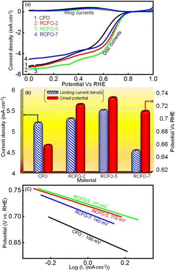 |
| | Fig. 5 (a) ORR ring-disc LSV profiles obtained for various catalysts in 0.1 M KOH electrolyte at the scan rate of 10 mV s−1, (b) comparison of ORR onset potential and limiting current densities and (c) Tafel plots obtained for the various catalysts. | |
The mechanism involving 2e− transfer proceeds via sluggish kinetics given that it involves a peroxide intermediate, while the 4e− transfer pathway results in direct H2O formation. To estimate the amount of H2O2 formed during the ORR, a fixed potential of 0.6 V vs. RHE was applied to the Pt ring electrode, while running the LSV technique on the catalyst-coated disc of the RRDE. The H2O2 formed on the disc will be subjected to oxidation on the Pt ring at this potential and the current response detected by the ring will be proportional to the amount of the H2O2 formed. All the generated catalysts including RCFO-5 showed no significant ring current response, as evidently seen in Fig. 5(a), suggesting the preferred 4e− transfer pathway. According to the ring current obtained in the LSV profile of the RCFO-5 catalyst, the quantitative measurement of the H2O2 and number of electrons transferred (n) during the ORR was carried out using the following eqs:34
| |  | (5) |
| |  | (6) |
where the disc- and ring-current are represented by
i(
d) and
i(
r), respectively, and
N = 0.37 is a unitless value known as the RRDE collection efficiency. Based on these equations, a plot was constructed, as depicted in
Fig. 6(a). It can be seen that the number of electrons transferred is close to 4 and the percentage of the H
2O
2 formed is as low as 1%. Moreover, the Koutecky–Levich (K–L) plots of the RCFO-5 catalyst were constructed using the K–L equation in
eqn (7) to substantiate the 4e
− transfer during the ORR, as follows:
| |  | (7) |
where
i,
iK and
iL are the total current density, kinetic and limiting current densities (mA cm
−2).
ω is the speed at which the electrode is rotated (rad s
−1) and the constant
B is the Levich constant, presenting information about the dissolved O
2 concentration, diffusion coefficient, and kinematic viscosity. To construct the K–L plots, the LSV plots at different electrode rotation speeds (400 to 1600 rpm) were obtained at a scan rate of 10 mV s
−1, as show in
Fig. 6(b). An increase in the current density was seen as the rotation speed increased, indicating a higher rate of the ORR. This trend is expected due to the improved mass transportation of the dissolved O
2 molecules under the hydrodynamic force during rotation. It was noted that the ORR proceeded at mixed-diffusion rates at higher potentials and in a kinetically limited manner in the low potential range of 0–0.5 V given that the current response in this region is nearly stationary. Subsequently, the K–L plots were plotted, as shown in
Fig. 6(c), at different potentials of 0.4, 0.5, 0.6 and 0.7 V. The obtained K–L plots were seen to be linear and parallel to each other, as observed for first-order ORR reaction kinetics with 4e
− transfer.
 |
| | Fig. 6 (a) Quantification of the H2O2 formed and the number of electrons transferred in ORR, (b) ORR LSV profiles at varying electrode rotation speeds of RRDE at a sweep rate of 10 mV s−1, and (c) K–L plots at multiple potentials derived from the speed-dependent LSV plots of the RCFO-5 composite electrocatalyst recorded in 0.1 M KOH. | |
Moreover, the OER kinetics of CFO and the composite catalysts were also evaluated utilizing the LSV technique. The LSV profiles in the potential region of 1–2 V vs. RHE, as shown in Fig. 7(a), were obtained at a sweep rate of 10 mV s−1 in 0.1 M KOH electrolyte saturated with argon gas. The onset potentials and the limiting current densities of CFO and the composite catalysts were extracted from these LSV profiles and plotted in Fig. 7(b). It is known that a lower onset potential for OER indicates a better catalyst. According to Fig. 7(b), it can be seen that the onset potentials of the composites moved to lower potentials as the amount of RuO2 increased in the composites although the difference between the RCFO-5 and RCFO-7 catalysts was marginal. Notably, as seen in the ORR analyses, the RCFO-5 catalyst exhibited superior OER activity on further analyses. For example, the limiting current density achieved on the RCFO-5 catalyst (21 mA cm−2) was greater than that on the other composite catalysts, as shown in Fig. 7(b). Moreover, the Tafel slopes of the catalysts were calculated from the constructed Tafel plots, as shown in Fig. 7(c). The RCFO-5 catalyst delivered the lowest Tafel slope of 160 mV dec−1 compared to the RCFO-2 (162 mV dec−1) and RCFO-7 (166 mV dec−1) catalysts. In all these analyses, the RuO2 composite exhibited improved metrics compared to the pristine CuFe2O4 catalyst. The presence of RuO2 with its loading as low as 2 wt% could reduce the Tafel slope of CuFe2O4 (230 mV dec−1), indicating the effectiveness of embedding the RuO2 in the CuFe2O4 matrix for enhanced OER performance.
 |
| | Fig. 7 (a) OER LSV profiles of the composite catalysts and the pristine CFO catalyst recorded at 10 mV s−1, (b) comparison of OER onset potential and limiting current densities and (c) OER Tafel plots with slope recorded for the various catalysts in 0.1 M KOH. | |
The stability tests for CFO and the RCFO composite catalysts towards ORR and OER were conducted by running LSV for 250 cycles at a scan rate of 10 mV s−1. The obtained LSV plots for the first and 250th ORR cycles are shown in Fig. 8(a–d). The RCFO-5 composite catalyst was found to be the most stable, given that its LSV curves obtained in the first and 250th cycles overlapped. Similarly, in the OER stability tests, the RCFO-5 composite catalyst maintained a very high limiting current density of 17 mA cm−2 at the end of the 250th cycle. In contrast, the CFO catalyst could only achieve a limiting current density of about 12 mA cm−2 at the beginning, which deteriorated to as low as 4 mA cm−2 in the 250th cycle. Although the other RuO2-embedded composites showed better activity than the pristine CFO catalyst, they did not match the performance of the RCFO-5 catalyst. These results are confirmed by the LSV profiles from the stability tests, as shown in Fig. 8(e–h).
 |
| | Fig. 8 (a–d) ORR cycle-life data and (e–h) OER cycle-life analysis of the CFO and the composite catalysts in 0.1 M KOH electrolyte recorded at 10 mV s−1 scan rate. | |
3.3 Performances of RCFO-5 cathode catalyst in Li–O2/Li–air/Li–CO2 batteries
Given that the RCFO-5 composite catalyst showed superior ORR and OER activities in the RRDE experiments, the composite catalyst was further applied in real-life Li–O2, Li–air and Li–CO2 battery studies. Initially, the enhanced electrochemical performance of the RuO2-based composite catalysts compared to the pristine catalyst in the Li–O2 battery was evaluated by recording a GCD profile at a current rate of 500 mA g−1. The result, as displayed in Fig. S4,† shows that the RCFO-5 catalyst exhibits lowest overpotential in the charge–discharge profiles, confirming its enhanced RRDE performance. The effect of introducing the RuO2 in CuFe2O4 improved the electrochemical performance of the Li–O2 battery, as observed in the reduction of the overpotential (Fig. S4†) for the Li–O2 battery. Each of these batteries in the form of CR-2032 coin cells were initially tested for their ability to hold the open circuit voltage (OCV) when opened to the respective atmospheres of pure O2, mixed atmosphere of O2/CO2 (10%) and pure CO2. The purpose of performing the additional tests on the Li–O2 battery was to examine the influence of CO2 its performance, which led to the optimization of the practicality of the Li–O2 battery. The required environment of these gases was generated in a home-made container sealed with an air-tight balloon. A pictorial representation of this container is shown in the inset of Fig. 9(a). The obtained self-decay profiles recorded for the Li–O2, Li–air and Li–CO2 batteries showed their capability to hold a stable voltage for more than six days, as shown in Fig. 9, demonstrating their potential in practical applications. The inset of Fig. 9(c) shows the observed OCV of the Li–air battery in a digital multimeter. Thus, further studies were conducted using each battery. To estimate the capacity that can be derived from these batteries having the RCFO-5 cathode catalyst, rate capability tests were conducted by means of the galvanostatic charge–discharge (GCD) technique at varying current densities. To derive any capacity from a rechargeable Li–O2 battery, a potential cathode catalyst must catalyze the reduction of atmospheric O2 during the discharge and oxidation of Li2O2 (discharge-product) to metallic lithium and molecular O2 during charging. The reactions happening upon the aforementioned discharging of the Li–O2 battery are given below, whereas the reactions in the reverse direction will be forced to happen upon charging:
 |
| | Fig. 9 (a, c, e) OCV decay profiles of the Li–O2, Li–air and Li–CO2 batteries with inset showing the CR2032 Li–air coin cell connected to a voltameter displaying the cell voltage and (b, d, f) rate capability analyses of the Li–O2, Li–air and Li–CO2 batteries using the RCFO-5 cathode catalyst. | |
At anode:
| | | 2Li → 2Li+ + 2e−, E0 = −3.04 vs. RHE | (8) |
At cathode:
| | | 2O2 + 2e− → 2O2−, E0 = −0.08 V vs. RHE | (9) |
Overall reaction:
| 2Li + 2O2 → 2Li2O2, Ecell = 2.96 V10 |
Thus, to estimate the capacity of the cell at various current rates, the Li–O
2 battery having the RCFO-5 catalyst-coated cathode and a lithium chip as the anode was subjected to discharging and charging in the potential window of 2.0–4.5 V
vs. Li/Li
+. The cell was initially forced to discharge at the current densities of 200, 300 and 500 mA g
−1, and then charged at the same current rate, and the obtained GCD curves are depicted in
Fig. 9(b). At the current density of 200 mA g
−1, an excellent discharge capacity of 14
250 mA h g
−1 was achieved. Furthermore, even at higher current densities of 300 and 500 mA g
−1, capacities as high as 6000 and 1500 mA h g
−1 were attained, respectively. These discharge curves have the advantageous trait of steady discharge voltage of roughly 2.5 V over most of the capacity. To decompose the discharge product Li
2O
2 on charging, a high voltage beyond 4.0 V is generally required due the stable and insulative nature of the discharge product Li
2O
2. Here, on the RCFO-5 composite catalyst, the charge voltage plateau was observed at the relatively low voltage of 4.0 V. According to the above-mentioned study, it was determined that the Li–O
2 battery (note: pure O
2 as the cathode) using the developed composite cathode catalyst showed a satisfactory performance, given that a high discharge capacity was obtained. However, the use of a pure O
2 atmosphere as the cathode in an Li–O
2 battery is impractical given that the ambient environment only has 21 vol% O
2 together with CO
2 and other gases.
Thus, the battery tests conducted on the RCFO-5 composite catalyst in a pure O2 atmosphere (Li–O2 battery) was impractical compared to the more attractive open-air system known as the Li–air battery. The major challenge here is to determine the impact of the CO2 present in the atmosphere on the battery. Although the presence of CO2 was reported to have some advantages in the Li–air battery,14 the decomposition of Li2CO3 formed on discharging is a major challenge in the cathode catalyst. Furthermore, the huge band gap and the thermodynamic stability of Li2CO3 make it difficult to re-oxidize on charging. Although the Earth's atmosphere only has 0.4 vol% of CO2, a strained atmosphere of 10 vol% CO2 and 90 vol% O2 was selected to explore the influence of CO2 on the performance of the Li–air battery. Thus, initially rate capability tests by means of the GCD technique at 100, 200, 300 and 500 mA g−1 were carried out, as shown in Fig. 9(d). The discharge capacities of 12800, 10680, 5200 and 3000 mA h g−1 were obtained at these current densities, respectively. These capacities derived from the Li–air battery were lower compared with that of the Li–O2 battery at the same current density (Fig. 9(b)). This reduction can only be attributed to the presence of CO2 in the given gas atmosphere given that it was the only difference compared to the conditions in Fig. 9(b).
It was observed that the Li–air battery (10% CO2 + 90% O2) delivered a diminished capacity compared to that of the Li–O2 battery (100% O2) using the same composite cathode catalyst. Given that the only difference here was the introduction of 10% CO2 together with 90% O2, it had a clear influence on the discharge capacity of the Li–air battery. To examine the impact of CO2 on the activity of the catalyst, further analysis on the battery working in a pure CO2 atmosphere was separately performed. Thus, rate capability tests on the Li–CO2 (Li‖CO2) battery by means of GCD analyses were executed at different current densities. The obtained GCD profiles at current densities of 100, 200 and 300 mA g−1 are shown in Fig. 9(f), achieving the capacities of 620, 270, and 90 mA h g−1, respectively. It was noticed that the discharge and charge capacities were notably lower, with a large difference between them, indicating that the catalyst was not able to oxidize or decompose the Li2CO3 discharge product completely. It should be noted that the Li–CO2 battery (pure CO2 on the cathode atmosphere) is also not a practical battery in the aforementioned atmosphere given that the ambient air contains mostly 21 vol% O2, not a 100% CO2. This battery may be preferred where a pure CO2 atmosphere is present such as in Mars or where CO2 is prevalent such as industrial furnaces.35
A similar performance trend in the cyclic stability test was observed when moving to the Li–CO2 battery from the Li–O2 battery. The cycling stability, a practically more important feature of a battery, was analyzed by running multiple cycles of GCD at a current rate of 100 mA g−1 with a charge–discharge capacity cutoff at 1000 mA h g−1. As can be observed in Fig. 10(a), the Li–O2 battery (100% O2) demonstrated almost stable charge–discharge capacities, with a minor decrease in the capacity seen in the 10th cycle. Moreover, the overpotential measured in the Li–O2 battery, which is the difference in voltage between the charging plateau and discharging plateau, is lower when compared with that of the Li–air battery. The overpotential of the Li–O2 battery (100% O2) at the capacity of 200 mA h g−1 was measured to be 1200 mV (Fig. 10(a)). In contrast, the capacity of the Li–air battery (10% CO2 + 90% O2) began to fade after a few cycles, as observed in Fig. 10(b), because of the Li2CO3 buildup in the pores of the cathode catalyst, making it difficult for the catalyst to break it down over the cycles. By the 10th cycle, the capacity diminished to as low as 477 mA h g−1. Moreover, the polarization overpotential measured in the Li–air battery (Fig. 10(b)) was as high as 1800 mV, which is higher than the polarization voltage observed for the Li–O2 battery (Fig. 10(a)). Thus, the catalyst needed a much higher input voltage to decompose the discharge product in the Li–air battery. Notably, the cyclic stability of the RCFO-5-based Li–CO2 battery (100% CO2) was also tested by running multiple cycles of GCD at 100 mA g−1, as depicted in Fig. 10(c). Although the cell could achieve the limiting high capacity of 1000 mA h g−1 for up to three cycles, the charging capacity was phenomenally low, and the discharge capacity diminished simultaneously, indicating that the catalyst could not completely oxidize the carbonate/oxalate-based discharge product. Consequently, rapid fading of the cell capacity occurred, and by the 10th cycle, the capacity of the Li–CO2 battery plummeted to as low as 50 mA h g−1. This implies that under a pure CO2 environment, the Li–CO2 battery performance was severely affected due to the formation of Li2CO3, which requires a high decomposition potential, clogging the catalyst pores, and thereby retarding the CO2 uptake.
 |
| | Fig. 10 (a–c) The cycle life performance of the Li–O2, Li–air and the Li–CO2 batteries at 100 mA g−1 using the RCFO-5 the cathode catalyst and (d) CV profiles recorded in various atmospheres of Ar, O2 and CO2 at a scan rate of 0.1 mV s−1. Inset: Zoomed-in CV profile of Li–CO2 battery in comparison with its performance in an inert Ar-atmosphere. | |
3.4 Mechanism of Li–O2/Li–CO2 batteries
A deeper understanding of the reaction mechanism and the electrolytic stability in the Li–O2 and the Li–CO2 batteries were acquired by analysing the CV profiles recorded at 0.1 mV s−1 on the Li–O2 and Li–CO2 batteries. Here, the CV profile in an atmosphere of Ar was also recorded to understand the stability of the electrolyte in the absence of any active species such as O2 and CO2. The obtained profiles are given in Fig. 10(d). The CV profiles recorded on the Li–O2 battery demonstrated an onset potential of about 2.8 V vs. Li/Li+ on the cathodic sweep of the O2 reduction reaction, which is close to the theoretical potential, as shown in eqn (10). The oxidative peak of the CV profile was observed at about 4 V, consistent with the previously observed charging plateau potential (Fig. 9(b)). At a higher potential above 4.2 V, there was a sharp increase in the current density, which can be correlated with the electrolytic decomposition promoted by the aggressive reaction intermediate such as superoxide (O2−) during the ORR. When these observations are compared with the CV profile obtained in an Ar atmosphere, the intermediate (O2−)-promoted electrolyte decomposition was more evident. Specifically, the non-negligible current spike observed at higher potentials (>4.2 V) even in the absence O2 reveals the instability of the electrolyte at higher voltages, which was amplified in the presence of O2 due to the formation of the intermediate.
Further information about the electrolyte stability and reaction mechanism was gathered from the CV profile of the Li–CO2 battery. For better visibility, the CVs recorded in the CO2 and Ar atmospheres are given in the inset of Fig. 10(d). The reduction of CO2 on the RCFO-5 catalyst in the Li–CO2 battery proceeds through multiple steps at the potentials of 2.9, 2.6, and around 2.0 V vs. Li/Li+. Although the theoretical potential of Li2CO3 formation is 2.8 V, the sluggish kinetics of the reaction will make the actual reaction potential lower.36 Thus, the peak appearing at around 2.6 V is designated to the reduction reaction to form Li2CO3 according to eqn (10). The less obvious peak located at 2.9 V is attributed to the formation of Li2C2O4 according to eqn (11). It is known that Li2C2O4 as a discharge product is a preferred product in the Li–CO2 battery.36 The lower peak appearing at around 2.0 V is correlated with the formation of Li2O according to eqn (12).
| | | 3CO2 + 4Li → 2Li2CO3 + C, E0 = 2.80 V (vs. Li/Li+) | (10) |
| | | 2CO2 + 2Li → Li2C2O4, E0 = 3.02 V (vs. Li/Li+) | (11) |
| | | 4Li+ + CO2 + 4e− → 2Li2O + C, E0 = 1.89 V (vs. Li/Li+) | (12) |
The oxidation peaks mainly appeared at around 3.4 V, corresponding to the decomposition of Li2C2O4 and 3.6 V for the decomposition of Li2CO3.36 Another interesting observation that can be made here is the electrolyte protection due to the presence of CO2, as reported elsewhere.14 The current density related to the electrolyte decomposition at higher voltages (>4.2) observed in the Ar atmosphere was more suppressed in the presence of CO2 (Fig. 10(d) inset). Additionally, this suppressed peak corresponding to the decomposition of the electrolyte in the Li–CO2 battery shifted to a higher voltage 4.4 V, suggesting that the electrolyte is more safeguarded in the presence of CO2.
Thus, the reduced capacities and cycle-life stability of the Li–air and Li–CO2 batteries can only be due to the incomplete decomposition of the discharge products (Li2C2O4/Li2CO3) and not due to any electrolyte-related issues given that the electrolyte is more protected in the presence of the CO2. The lack of the complete reoxidation of the lithium-carbonate/oxalate generated on the pores of the cathode during the discharge caused a huge resistive load on the cathode over multiple cycles. To verify this, electrochemical impedance spectroscopy studies at various discharge voltages for 1st and 5th cycles were performed. The Nyquist plots acquired from these measurements are given in Fig. 11(a and b). The obtained Nyquist plots were fit using an equivalent circuit, as presented in ESI Fig. S6,† and used to calculate the charge-transfer resistance (Rct). The Rct of the Li–CO2 battery increased from 271 Ω at 3.1 V to 366 Ω at 2.0 V in the first discharge, as shown in Table S1.† The build-up of insulating Li2CO3 in the pores of the cathode as the cell discharges resulted in this increase in Rct. However, more evidently, the Rct at the end of 5th cycle increased further to a high resistance of 600 Ω at 2.0 V. These observations suggest that the discharge products were not completely decomposed and their accumulation increased over multiple cycles. Moreover, the presence of the carbonate discharge product remaining on the cathode catalyst after recharging was further confirmed by the postmortem XRD analysis. For this, the XRD pattern of the fresh electrode was recorded before the battery discharging. The electrode of another cell was also subjected to XRD after the first discharge followed by first charge. These two XRD patterns before and after the first discharge–charge are shown in Fig. 11(c). This electrode powder for the XRD analysis was collected by taking the electrode out of the dismantled battery after charging the cell, followed by washing with ethanol and drying. The XRD pattern of the discharged electrode shows a peak corresponding to Li2CO3 even after the charging of the battery together with peaks of the coated-catalyst material and that of the carbon substrate used as the gas diffusion layer. Based on the aforementioned results, the overall reactions that are catalyzed on the RCFO-5 catalyst are schematically summarized in Fig. 11(d). It seems that the added RuO2 acted as catalytic centres to promote the ORR/OER rates, resulting in high kinetics and discharge capacity. The enhanced reaction centres facilitated an improvement in the discharge capacity of the Li–O2 battery.
 |
| | Fig. 11 Nyquist plots recorded in the frequency range of 0.1 Hz to 10 kHz at various stages of discharge in (a) 1st and (b) 5th cycles in a CO2 atmosphere. (c) Postmortem analyses using XRD patterns of initial, discharged and charged RCFO-5 cathode catalyst and (d) schematic of all the catalytic reactions happening on the RuO2@CuFe2O4 catalyst used in the Li–air and Li–CO2 batteries. | |
3.5 Demonstration of prototype Li–air|Li–CO2 batteries
The practical applications of the Li–air and Li–CO2 batteries were demonstrated by lighting a 2.8 V commercial LED bulb in an open atmosphere and a closed container filled with CO2, respectively. The Li–air battery could power the bulb for a long period and a timeline-photographic representation is given in Fig. 12(a–c). In the case of the Li–CO2 battery, the CO2 atmosphere was introduced in in a 250 mL RB flask sealed with a balloon. The container was purged with pure CO2 intentionally after placing the LED bulb connected to the Li–CO2 battery inside. Within the 12 h of powering the LED bulb, the CO2 gas inside the flask was almost utilized, as seen by the suction of the balloon inside the RB flask. On refilling the CO2 gas, the powering of the LED bulb was noted, demonstrating the functional Li–CO2 battery using the RuO2@CuFe2O4 cathode catalyst. These observations are pictorially represented in Fig. 12(d–f). Thus, the addition of RuO2 could increase the reaction centres, which facilitated high ORR/OER kinetics and high discharge capacity for the Li–air battery. The CO2 had a diminishing effect on the Li–air battery performance but provided a safe cycling of the electrolyte.
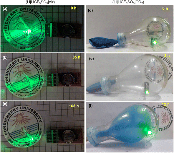 |
| | Fig. 12 (a–c) Timeline photographs showing the intensities of the glowing LED bulb, powered by the Li–air cell and (d–f) CO2 utilization on discharge of Li–CO2 battery while powering a commercial green LED in a pure CO2 atmosphere maintained inside a round-bottom flask. | |
4. Conclusions
According to this study, it can be concluded that a very small quantity of RuO2 as low as 5 wt% embedded in the inverse spinel CuFe2O4 drastically improved the ORR/OER kinetics, imparting very good stability to the catalyst for the ORR/OER in 0.1 M KOH electrolyte. An improved current density response, onset potential and Tafel slope were achieved on the RuO2-embedded CuFe2O4. The in-depth electrocatalytic investigations revealed a 4e− transfer pathway with insignificant H2O2 formation in the ORR. A commendable OER performance with good stability and a low Tafel slope were achieved in the OER using this catalyst. The excellent ORR/OER performances were sustained on extending the study to an Li–air battery. The Li–O2 battery operating in a pure O2 atmosphere gave a high capacity of 14250 mA h g−1 at a current density of 200 mA g−1. The impact of CO2 on the performance of this enhanced battery catalyst was investigated via a wide variety tests in Li–air and Li–CO2 batteries including CV, GCD, postmortem XRD analyses and electrochemical impedance spectroscopy. The traces of Li2CO3 in the catalyst pores observed in the postmortem analysis of the electrode indicated that the RuO2@CuFe2O4 catalyst could not completely re-oxidize the carbonate, which is consistent with the impedance observation of increasing charge-transfer resistance over several charge–discharge cycles in a CO2 atmosphere.
Data availability
The data that support the findings of this study are available from the corresponding author upon reasonable request.
Conflicts of interest
There are no conflicts to declare.
Acknowledgements
PE thanks Science and Engineering Research Board (SERB), Govt. of India for the research grant (CRG/2021/005678). The authors acknowledge the Central Instrumentation Facility of Pondicherry University and the Gandhigram Rural Institute for the characterisation facilities. PCS thanks MNRE, Govt. of India for NREF fellowship (F. No. 342-16/2/2022-HRD).
References
- K. N. Jung, J. Kim, Y. Yamauchi, M. S. Park, J. W. Lee and J. H. Kim, J. Mater. Chem. A, 2016, 4, 14050–14068 RSC.
- D. Geng, N. Ding, T. S. A. Hor, S. W. Chien, Z. Liu, D. Wuu, X. Sun and Y. Zong, Adv. Energy Mater., 2016, 6, 1502164 CrossRef.
- S. Sandhiya and P. Elumalai, Electrochim. Acta, 2024, 487, 144195 CrossRef CAS.
- H. Park, M. Kang, D. Lee, J. Park, S. J. Kang and B. Kang, Nat. Commun., 2024, 15, 1–11 Search PubMed.
- N. Imanishi and O. Yamamoto, Mater. Today Adv., 2019, 4, 100031 CrossRef.
- C. Allard, Nat. Rev. Mater., 2023, 8, 145 CrossRef.
- N. Garcia-Araez and P. Novák, J. Solid State Electrochem., 2013, 17, 1793–1807 CrossRef CAS.
- W. Li, M. Zhang, X. Sun, C. Sheng, X. Mu, L. Wang, P. He and H. Zhou, Nat. Commun., 2024, 15(1), 1–11 CAS.
- Y. Shao, F. Ding, J. Xiao, J. Zhang, W. Xu, S. Park, J. G. Zhang, Y. Wang and J. Liu, Adv. Funct. Mater., 2013, 23, 987–1004 CrossRef CAS.
- T. Liu, J. P. Vivek, E. W. Zhao, J. Lei, N. Garcia-Araez and C. P. Grey, Chem. Rev., 2020, 120, 6558–6625 CrossRef CAS PubMed.
-
V. Sankar Devi, M. Athika, S. Sandhiya and P. Elumalai, in Nano-electrocatalyst for Oxygen Reduction Reaction Fundamentals to Field Applications: Recent Developments of Transition Metal Oxide Nanoparticles on Oxygen Reduction Reaction, ed. O. Solorza-Feria, K. Sathish-Kumar, CRC Press, 2024, ch. 2 Search PubMed.
- K. Takechi, T. Shiga and T. Asaoka, Chem. Commun., 2011, 47, 3463–3465 RSC.
- W. Yin, A. Grimaud, F. Lepoivre, C. Yang and J. M. Tarascon, J. Phys. Chem. Lett., 2017, 8, 214–222 CrossRef CAS PubMed.
- K. Chen, G. Huang, J. L. Ma, J. Wang, D. Y. Yang, X. Y. Yang, Y. Yu and X. B. Zhang, Angew. Chem., Int. Ed., 2020, 59, 16661–16667 CrossRef CAS PubMed.
- S. L. Tian, L. N. Song, L. M. Chang, W. Q. Liu, H. F. Wang and J. J. Xu, Nano Energy, 2024, 126, 109677 CrossRef CAS.
- S. L. Tian, M. L. Li, L. M. Chang, W. Q. Liu and J. J. Xu, J. Colloid Interface Sci., 2024, 656, 146–154 CrossRef CAS PubMed.
- L. Wang, X. Zhao, Y. Lu, M. Xu, D. Zhang, R. S. Ruoff, K. J. Stevenson and J. B. Goodenough, J. Electrochem. Soc., 2011, 158, A1379 CrossRef CAS.
- K. N. Jung, J. I. Lee, S. Yoon, S. H. Yeon, W. Chang, K. H. Shin and J. W. Lee, J. Mater. Chem., 2012, 22, 21845–21848 RSC.
- Q. Li, P. Xu, B. Zhang, H. Tsai, J. Wang, H. L. Wang and G. Wu, Chem. Commun., 2013, 49, 10838–10840 RSC.
- R. S. Kalubarme, H. S. Jadhav, D. T. Ngo, G. E. Park, J. G. Fisher, Y. Il Choi, W. H. Ryu and C. J. Park, Sci. Rep., 2015, 5, 1–12 Search PubMed.
- L. Zou, J. Cheng, Y. Jiang, Y. Gong, B. Chi, J. Pu and L. Jian, RSC Adv., 2016, 6, 31248–31255 RSC.
- Y. Gong, W. Ding, Z. Li, R. Su, X. Zhang, J. Wang, J. Zhou, Z. Wang, Y. Gao, S. Li, P. Guan, Z. Wei and C. Sun, ACS Catal., 2018, 8, 4082–4090 CrossRef CAS.
- X. Li, T. Zhu, C. Wen, Y. Yang, S. Ma, X. Huang, H. Li and G. Sun, Electrochim. Acta, 2019, 317, 367–374 CrossRef CAS.
- M. Athika and P. Elumalai, ChemElectroChem, 2020, 7, 4188–4200 CrossRef CAS.
- K. M. Naik, ACS Appl. Energy Mater., 2021, 4, 1014–1020 CrossRef CAS.
- S. Karunarathne, Y. Y. Kannangara, C. R. Ratwani, C. Sandaruwan, W. P. S. L. Wijesinghe, A. R. Kamali and A. M. Abdelkader, Nanoscale, 2024, 16, 7937–7950 RSC.
- M. Hosseini, J. Adv. Mater. And Technol., 2020, 9, 26–34 Search PubMed.
- H. S. Park, E. Seo, J. Yang, Y. Lee, B. S. Kim and H. K. Song, Sci. Rep., 2017(7), 1–9 Search PubMed.
- R. S. Yadav, J. Havlica, J. Masilko, L. Kalina, J. Wasserbauer, M. Hajdúchová, V. Enev, I. Kuřitka and Z. Kožáková, J. Supercond. Novel Magn., 2016, 29, 759–769 CrossRef CAS.
- S. Carenco, C. Sassoye, M. Faustini, P. Eloy, D. P. Debecker, H. Bluhm and M. Salmeron, J. Phys. Chem. C, 2016, 120, 15354–15361 CrossRef CAS.
- Y. Wang, L. Dong, R. Xiong and A. Hu, J. Mater. Chem. C, 2013, 1, 7731–7735 RSC.
- J. Zhao, P. Xiao, S. Han, M. Zulhumar and D. Wu, Water Sci. Technol., 2022, 85, 645–663 CrossRef CAS PubMed.
- X. Li, A. Liu, D. Chu, C. Zhang, Y. Du, J. Huang and P. Yang, Catalysts, 2018, 8, 108 CrossRef.
- W. Yan, W. Bian, C. Jin, J. H. Tian and R. Yang, Electrochim. Acta, 2015, 177, 65–72 CrossRef CAS.
- X. Zhang, C. Wang, H. Li, X. G. Wang, Y. N. Chen, Z. Xie and Z. Zhou, J. Mater. Chem. A, 2018, 6, 2792–2796 RSC.
- Y. F. Wang, L. N. Song, L. J. Zheng, Y. Wang, J. Y. Wu and J. J. Xu, Angew. Chem., 2024, 136, e202400132 CrossRef.
|
| This journal is © The Royal Society of Chemistry 2024 |
Click here to see how this site uses Cookies. View our privacy policy here. 
 and
Perumal
Elumalai
and
Perumal
Elumalai


