 Open Access Article
Creative Commons Attribution 3.0 Unported Licence
Carbon nitride- and graphene-based materials for the photocatalytic degradation of emerging water pollutants
Indra Jaya
Budiarso
 a,
Valentinus Alphano
Dabur
a,
Riska
Rachmantyo
b,
Hermawan
Judawisastra
c,
Chechia
Hu
a,
Valentinus Alphano
Dabur
a,
Riska
Rachmantyo
b,
Hermawan
Judawisastra
c,
Chechia
Hu
 de and
Arie
Wibowo
 *cf
*cf
aMaster Program in Materials Science and Engineering, Faculty of Mechanical and Aerospace Engineering, Institut Teknologi Bandung, Ganesha 10, Bandung, 40132, West Java, Indonesia
bDoctoral Program in Materials Science and Engineering, Faculty of Mechanical and Aerospace Engineering, Institut Teknologi Bandung, Ganesha 10, Bandung, 40132, West Java, Indonesia
cMaterials Science and Engineering, Faculty of Mechanical and Aerospace Engineering, Institut Teknologi Bandung, Ganesha 10, Bandung, 40132, West Java, Indonesia. E-mail: ariewibowo@itb.ac.id
dDepartment of Chemical Engineering, National Taiwan University of Science and Technology, Taipei 106, Taiwan
eR&D Center for Membrane Technology, Chung Yuan Christian University, Taoyuan 320, Taiwan
fResearch Center for Nanoscience and Nanotechnology, Institut Teknolgi Bandung, Ganesha 10, Bandung, 40132, West Java, Indonesia
First published on 27th February 2024
Abstract
Photocatalytic degradation is a promising way to treat emerging pollutants in wastewater. Recently, metal-free photocatalysts such as carbon nitride- and graphene-based materials have attracted much interest in the photocatalytic degradation of emerging water pollutants owing to their visible light activity and unique electrical properties, respectively. Graphitic carbon nitride (GCN) is considered a superior visible light–active photocatalyst because of its suitable bandgap (2.7 eV). Moreover, the facile synthesis process and the high chemical and thermal stability of GCN make it one of the research hotspots in photocatalytic wastewater treatment. Besides GCN, graphene and its derivatives are utilized to support main photocatalysts by enhancing their light absorption, pollutant adsorption, and photogenerated charge separation. Furthermore, the vast modification of these materials has promoted various outstanding performances in carbon nitride- and graphene-based photocatalysts in the application of pollutant degradation. In this review, we highlight recent developments in carbon nitride- and graphene-based photocatalysts (2018–2023), focusing on the strategies to improve the activity of GCN as a visible light–active photocatalyst and the role of graphene and its derivatives as supporting materials in wastewater pollutant remediation applications.
1. Introduction
Water is an abundant natural resource widely used for daily activities and industrial needs. However, around 80% of industrial and municipal wastewater is discharged into the environment without prior treatment.1 In 2020, the WHO reported that over 2 billion people live in countries experiencing water scarcity, and approximately 2 billion people consume contaminated drinking water. Moreover, the rapid industrial growth has further exacerbated this situation.2 Together with industrial growth, many emerging pollutants, which are mainly classified as persistent, bioaccumulative, and toxic compounds (PBTs), are produced and discharged into the environment without any prior treatment. This group of pollutants is toxic, resistant to degradation, and tends to accumulate in living organisms.3 The identified pollutants classified as PBTs include heavy metals,4 pesticides,5 industrial substances,6 organobromines,7 polycyclic aromatic hydrocarbons (PAHs),8 pharmaceutical substances,9 and synthetic dyes.10 Long-term exposure to these substances has the potential to cause cancer, neurological problems, and hormone imbalances.11–13 Considering the significant negative impacts of their existence as waste, it is necessary to implement wastewater treatment technologies to eliminate PBTs from water sources.Several strategies have been used to reduce the presence of PBTs in water, including filtration,14–16 flocculation/coagulation,17,18 chemical precipitation,19 adsorption,16,20 ion exchange membranes,21 and Fenton-like catalysts.22,23 However, the majority of these methods have several disadvantages, such as high energy requirements, complex processes, and the generation of byproducts such as sludge and sediment.24 Thus, considering these limitations, it is necessary to develop low-cost methods that are simple, generate no toxic byproducts, and consume less energy. In this case, the photocatalytic degradation of pollutants in wastewater using solar light is considered a green method because of its simple process, mild operation conditions, and low cost.25,26
In photocatalytic wastewater treatment, the key idea is to generate energetic electron–hole (e–h) pairs, which will produce excess radical compounds such as hydroxyl radicals (OH˙) that can degrade PBT pollutants through an oxidation reaction.27 In detail, when light is irradiated on the photocatalyst, an electron will get excited to the conduction band (CB), leaving a hole in the valence band (VB). These photogenerated charge carriers will diffuse through the material and finally reach the surface of the material to produce radical compounds.27 Based on the mechanism, the bandgap and band position, charge diffusion pathway, and charge recombination in the photocatalyst must be optimized to obtain highly efficient photocatalyst materials towards pollutant degradation. In addition, conventional photocatalysts such as TiO2 can only be activated in the UV region, limiting their application in solar light-driven photocatalysts. Therefore, visible light-driven photocatalysts are gaining much more interest given that visible light is sufficiently energetic and accounts for 44% of the solar light spectrum.28
Carbon nitride-based and graphene-based materials are gaining interest in photocatalytic wastewater treatment due to the ease of their synthesis, large surface area, heterojunction construction possibilities, and shorter charge carrier migration pathway.29,30 Graphitic carbon nitride (GCN), which is a metal-free, visible light-active (band gap of 2.7 eV) layered structured photocatalyst consisting of carbon (C) and nitrogen (N), has been used in photocatalytic wastewater treatment to remove antibiotics, synthetic dyes, and bacteria.31–33 The development of GCN started in the mid-1800s and its application and synthesis method continue to expand.34,35 Nowadays, 2D GCN is still a research hotspot in photocatalytic wastewater treatment as an active photocatalyst. Many strategies have been developed to enhance the properties of pristine 2D GCN, such as pore formation, combination with cocatalyst, heteroatom doping, and fabrication of highly crystalline GCN.36–40 These strategies have been shown to successfully improve the photocatalytic activity of GCN materials towards pollutant degradation in wastewater. Specifically, herein, GCN refers to low-crystalline GCN.
Alternatively, 2D carbon-based materials such as graphene have high electrical conductivity and a large specific surface area.41 Moreover, the derivatives of graphene, such as graphene oxide (GO) and reduced-graphene oxide (rGO), have abundant surface functional groups, which endow them with high pollutant adsorption capability, allowance for further chemical modification, and the possibility to be integrated with other 2D materials.42 Hardiansyah et al. utilized rGO as a conductive material and added it to a TiO2 photocatalyst, which successfully prolonged the recombination time of the photogenerated electron–hole pairs, thus increasing its photocatalytic activity by three-fold.43 In another study, Al-Rawashdeh et al. suggested that the addition of GO to form a ZnO/GO nanocomposite significantly increased the surface area by almost three-fold, increasing the possibility of pollutant adsorption on the surface of the nanocomposite.
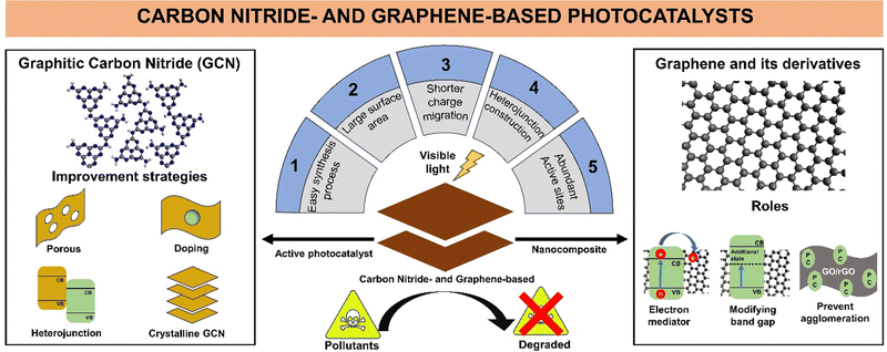
Due to the extensive research and high interest in carbon nitride and graphene-based photocatalysts for wastewater treatment, the number of carbon nitride and graphene-based photocatalyst materials continues to increase with various modification techniques. This review highlights the recent development (2018–2023) in carbon nitride-based and graphene-based materials as active photocatalysts and supporting materials, respectively, to provide a better understanding of the historical development, synthesis process, applications, and modifications of both materials. A summary of the advantages of GCN as an active photocatalyst and its improvement strategy, graphene and its derivatives as nanocomposites, and their roles in photocatalytic wastewater remediation is illustrated in Fig. 1.
2. Graphitic carbon nitride (GCN) as an active photocatalyst
2.1. History of carbon nitride development
The history of carbon nitride begins with the first synthesis of “melon”, also known as Liebig's melon, by Liebig in 1834.34 However, the structure of Liebig's melon was unknown at that time. Following the previous work, a computational simulation of carbon nitride by Liu and Cohen in 1990 showed that carbon nitride can exist in five different phases, in which the graphitic phase is calculated to be the most stable phase at ambient pressure.44 The exact chemical structure of Liebig's melon was discovered experimentally in 2007 by Lotsch et al., where they stated that it is an infinite 1D chain of NH-bridged melem (C6N7(NH2)3) monomers connected through hydrogen bonds in a zigzag-geometry. Based on this study, Liebig's melon is now known as polymeric carbon nitride (PCN) or GCN, as in this article. In 2009, the first report on PCN as a photocatalyst for hydrogen production under visible light irradiation was reported by Wang et al.40 Interestingly, around the same time, research by Bojdys et al. in 2008 revealed that the condensation of dicyandiamide using a salt melt of lithium chloride and potassium chloride as the solvent resulted in a highly crystalline GCN with 2D condensed heptazine as the building blocks.45 However, another study by Wirnhier et al. in 2011 revealed that the molten salt-assisted synthesis method produced a crystalline structure termed poly(triazine imide) or PTI with intercalation of lithium and chloride ions.46 Recent research by Lin et al. in 2016 reported the preparation of tri-s-triazine-based (heptazine-based) crystalline GCN using pre-heated melamine as the precursor in combination with the molten salt method for the first time.36 They also showed the potential of crystalline GCN for the photocatalytic hydrogen evolution reaction (HER). The remarkable history of carbon nitride development has attracted significant interest in extending the application of carbon nitride not only in photocatalytic wastewater treatment, but also CO2 photoreduction47 and photocatalytic water splitting further.482.2. Structural features of carbon nitride materials
The most common carbon nitride material employed in photocatalytic wastewater treatment is GCN. GCN is a 1D chain of NH-bridged melem connected through hydrogen bonds in a zigzag manner, as shown in Fig. 2a. Its hydrogen-bonded chain is extended in a two-dimensional plane, and the adjacent layer is bonded through weak van der Waals force, forming a layered structure similar to graphene. The absence of long-range order in the 2D plane produces structural defects, which affect the optical properties of GCN given that the hydrogen bond-terminated edge can act as a recombination site for the photogenerated e–h pairs. | ||
| Fig. 2 (a) Polymeric carbon nitride, (b) triazine-based crystalline GCN and (c) heptazine-based crystalline GCN. Reprinted with permission from ref. 36 Copyright 2016, the American Chemical Society. | ||
Another carbon nitride material that has recently gained interest is crystalline GCN. In contrast to GCN, crystalline GCN has the properties of a long-range order of repeating units in the 2D plane. The repeating unit can be triazine- or heptazine-based, as shown in Fig. 2b and c, respectively. In crystalline GCN, the absence of hydrogen bonds in the layer minimizes the possibility of photogenerated charge recombination, which is beneficial for photocatalytic wastewater treatment. Similar to GCN, the layers of crystalline GCN are connected through a weak van der Waals force. Other crystalline GCNs currently successfully synthesized are poly(triazine imide) or PTI and poly(heptazine imide) or PHI, which will be discussed further herein.49
2.3. GCN and crystalline GCN synthesis
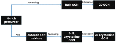
Bulk GCN can be synthesized via the thermal polymerization of a nitrogen-rich precursor, while crystalline GCN is usually synthesized by adding an eutectic salt mixture. Subsequently, the product is exfoliated through various methods such as thermal exfoliation, ultrasonic exfoliation and chemical exfoliation to obtain 2D GCN and crystalline GCN, respectively, as shown in Fig. 3.50,51 Additionally, many strategies have been attempted in combination with the molten salt-assisted method to obtain the desired material structure such as PTI, PHI, triazine-based crystalline GCN, and heptazine-based crystalline GCN.To obtain 2D GCN nanosheets, the bulk GCN must be exfoliated, which can be done in several ways, including ultrasonic, thermal, and chemical exfoliation.57 In ultrasonic exfoliation, Zhang et al. used compounds such as glycerol, water, and isopropyl alcohol, which will intercalate in the interlayer of GCN. Then, the ultrasonic sound will produce a localized high-energy region, breaking the van der Waals interaction between the sheets.58,59 A schematic illustration of the ultrasonic exfoliation method is shown in Fig. 4.
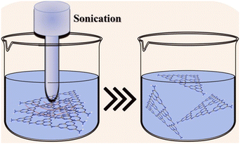 | ||
| Fig. 4 Schematic illustration of the ultrasonic exfoliation method. Reprinted with permission from ref. 60 Copyright 2023, Elsevier. | ||
A new thermal exfoliation method using the aqueous bi-thermal method was developed by Pattnaik et al. In this work, a mixture of bulk GCN and water was heated to accelerate the insertion of water into the interlayer of GCN. Subsequently, the dispersed GCN was subjected to deep freezing for about 8 h to form ice, expanding the water molecules and breaking the van der Waals interaction between the adjacent sheets.61 A schematic illustration of the aqueous bi-thermal GCN exfoliation method is shown in Fig. 5.
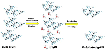 | ||
| Fig. 5 Schematic illustration of the bi-thermal exfoliation method. Reprinted with permission from ref. 61 Copyright 2019, Elsevier. | ||
In the chemical exfoliation method, concentrated sulfuric acid is used to assist the exfoliation process.62 Zhao et al. reported that it is possible to add oxidant to achieve an atomically thick GCN layer. Firstly, H2SO4 was intercalated into the interlayer of GCN by stirring a mixture of GCN and H2SO4 for 24 h, and then sodium nitrate (NaNO3) and potassium permanganate (KMnO4) were added. Finally, the product was diluted with 300 mL of deionized water and 30 wt% hydrogen peroxide to obtain a white product.63Fig. 6 shows a schematic illustration of the chemical exfoliation of GCN.
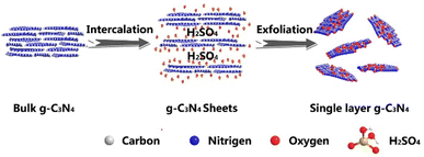 | ||
| Fig. 6 Schematic illustration of the chemical exfoliation method using H2SO4. Reprinted with permission from ref. 63 Copyright 2014, Springer Nature. | ||
The top-down approach can also be employed to synthesize porous GCN through pre-polymerization treatment. Wang et al. developed porous GCN by heating melamine powder at 350 °C for 2 h, cooling it, and grinding the product to expose more surfaces. Finally, the ground pre-heated melamine powder was reheated at 550 °C for 2 h to obtain porous GCN.64 An illustration of the synthesis process and SEM image of the porous GCN (inset) are shown in Fig. 7.
 | ||
| Fig. 7 Synthesis procedure of porous GCN using a pre-polymerization method. Inset: SEM image of porous GCN. Reprinted with permission from ref. 64 Copyright 2018, Elsevier. | ||
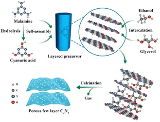 | ||
| Fig. 8 Synthesis process of self-assembled porous few-layer C3N4. Reprinted with permission from ref. 65 Copyright 2019, the American Chemical Society. | ||
Another type of bottom-up approach for the synthesis of GCN is through a template-assisted method. Sun et al. developed a two-dimensional (2D) heterostructure of TiO2 and GCN using Fe3O4 microplates as the template and sequentially growing a very thin layer of PCN and TiO2 on the microplate surface, followed by the removal of Fe3O4.66 In detail, Fe3O4 microplates were prepared via the hydrothermal method using K3Fe(CN)6 as the precursor. CN layers were grown on Fe3O4 through a solvothermal approach to obtain Fe3O4/CN. Then, a thin layer of TiO2 was grown on the surface of Fe3O4/CN through titanium(IV) butoxide (TBOT) hydrolysis, followed by calcination to obtain Fe3O4/CN/TiO2. Finally, the template was removed by HCl etching. The synthesis process of the template-assisted fabrication of 2D PCN/TiO2 heterostructure is schematically shown in Fig. 9a. The SEM image revealed that PCN still had a hexagonal plate-like shape with TiO2 particles deposited on the surface, as shown in Fig. 9b.
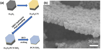 | ||
| Fig. 9 (a) Illustration of Fe3O4-template assisted fabrication of PCN/TiO2. (b) SEM image of PCN/TiO2. Reprinted with permission from ref. 66 Copyright 2023, Elsevier. | ||
The bottom-up synthesis also enables the preparation of crystalline GCN, such as PTI nanosheets, as reported in a recent study. Wang et al. prepared a crystalline GCN, namely, PTI/Li+Cl− with a condensed in-plane structure and lower structural defect density using a three system of eutectic salt mixture (LiCl/NaCl/KCl).67 They found that the ternary system preferred to extend the 2D π-conjugation plane, which favored the electron mobility compared to extension in the [001] direction. Moreover, the eutectic salt acts as a solvent and a structural template to guide the PTI crystallization process.
2.4. Modification of 2D GCN
2D GCN still suffers from insufficient photocatalytic activity mainly because of its fast electron–hole recombination and insufficient visible light absorption.68 Therefore, enormous efforts have been devoted to enhancing the properties of pristine 2D GCN using various strategies such as pore formation,69 heteroatom doping,70 combination with a cocatalyst,71 heterojunction construction,72 and fabrication of crystalline GCN. In addition, engineering the pristine 2D GCN will expand the applications of GCN to be integrated with other wastewater treatment methods such as self-cleaning membrane filters in filtration system.73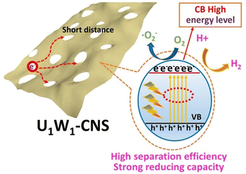 | ||
| Fig. 10 Schematic illustration of porous GCN. Reprinted with permission from ref. 74 Copyright 2021, Elsevier. | ||
Hou et al. successfully developed porous graphitic carbon nitride with N vacancy through the thermal treatment of bulk GCN under an H2 atmosphere.75 When heated under an H2 atmosphere, the N atom reacts with hydrogen, thus breaking the C–N bond and forming an N–H bond. The formation of the N–H bond leads to pore formation and increases the surface area (114 m2 g−1). Moreover, it possess higher light absorption possibly due to light trapping as a consequence of its porous morphology and low electron–hole pair recombination due to the short charge carrier pathway in reaching the active site. The photocatalytic degradation study showed that porous GCN with N vacancies could remove nearly 100% of 4-chlorophenol under visible light irradiation within 120 min.
Another porous GCN was synthesized by Chen et al. using carbon nanotubes (CNTs) as a hard template.76 In this work, porous GCN was synthesized by mixing dicyandiamide with multi-walled CNT and heating at 550 °C for 2 h under an N2 atmosphere. The obtained powder was dispersed in deionized water to precipitate the CNT. Finally, the mixture was centrifugated and dried to obtain the porous GCN. The obtained material possessed a high surface area (103.3 m2 g−1) and lower PL intensity, which showed enhanced electron–hole pair separation. Consequently, the photocatalytic degradation showed that the porous GCN is 2.52-times more effective against pollutants than the bulk GCN under visible light radiation.
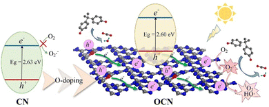 | ||
| Fig. 11 Illustration of the photocatalytic reaction mechanism of OCN. Reprinted with permission from ref. 78 Copyright 2022, Elsevier. | ||
Another doping strategy with transition metals (Cu, Mn, and Zn) was investigated by Hussain et al. In this work, urea was heated with metal salts such as CuCl2, MnCl2, and ZnCl2 for Cu, Mn, and Zn precursors, respectively.79 The methyl orange (MO) photocatalytic degradation study showed that Zn-doped GCN exhibited higher photocatalytic activity than pristine GCN. The authors suggested that the suppressed electron–hole recombination process and bandgap narrowing were the main reasons explaining the higher photocatalytic activity of the Zn-doped GCN.
Hu et al. developed GCN by mixing urea, melamine, and KCl to enhance the photocatalytic performance through the nanojunction between heptazine, which came from urea, and the triazine unit from melamine. The nanojunction could promote the charge separation process, and the presence of K+ and Cl− sites improved the electron–hole transfer. The photocatalytic activity study also strengthened the potential of the photocatalyst, in which almost 75% tetracycline (TC) degradation was achieved under the irradiation of visible light for 180 min.80
Another exciting application of graphitic carbon nitride is the development of a photocatalytic membrane reactor (PMR). Hu et al. synthesized a phosphorus-doped GCN-integrated photocatalytic membrane reactor for wastewater treatment.73 To synthesize P-doped GCN, hexachlorotriphosphazene (HCPP) was mixed with melamine, and then calcined at 520 °C for 6 h at a ramp rate of 1 °C min−1. The sample with a weight ratio of 10 HCPP (10PCN) exhibited the highest photocatalytic performance under visible light irradiation (> 90% MB degradation within 120 min). This enhancement is attributed to the proper amount of P atom that substitutes the C atom in the GCN crystal, creating a conductive path for photoexcited electron–hole pair separation and charge transfer to reach the active sites.
The combination of porous structure and P-doped GCN could enhance the photocatalytic activity of pristine GCN due to the increased number of active sites and enhanced electron–hole separation, as shown by Li et al.81 In this work, an ultrathin porous P-doped GCN nanosheet (PCN) was synthesized via a one-step thermal polymerization method by calcining a mixture of 1 g dicyanamide as the precursor, 5 g of ammonium chloride (NH4Cl) as the poring agent, and different amounts of 1-hydroxyethylidene-1,1-diphosphonic acid (HEDP) as the phosphorus source, which was denoted as PCN. The porous GCN was similarly prepared using the above-mentioned method without HEDP, which was denoted as CNN. Non-porous P-doped GCN was prepared without the addition of NH4Cl, which was denoted as CNP, and the pristine GCN was obtained without the addition of both NH4Cl and HEDP, which was denoted as GCN.81 The BET surface area measurement showed that PCN with 50 HEDP has a surface area of 73.850 m2 g−1, which was 8-times greater than that of the pristine GCN. According to the photoelectrochemical characterization, it is worth noting that the addition of a phosphor as a dopant significantly favoured the production of photogenerated charges and restrained the charge recombination due to the high capacity to lose electrons and the ease of electron delocalization of P the atom, respectively. Lastly, the photocatalytic activity of PCN with the addition of 50 mg of HEDP showed the most appealing performance because it could degrade diclofenac with 99.4% removal within 40 min under blue LED light irradiation.
Besides Au, GCN can be coupled with Ag to achieve a GCN plasmonic composite. Xu et al. successfully synthesized an Ag/porous GCN plasmonic photocatalyst and achieved 11.8-times higher degradation efficiency than pure GCN due to the improvement in visible-light absorption caused by the surface plasmon resonance (SPR) effect.82 In his work, porous GCN (pGCN) was obtained via direct calcination at 550 °C for 4 h, followed by further heat treatment at 530 °C for 3 h. Subsequently, Ag nanoparticles were deposited by adding AgNO3 to the pGCN suspension (0.5 g pGCN with 30 mL water) and irradiated for 2 h under a 300 W Xenon lamp. The schematic mechanism for the Ag/pGCN photocatalyst under visible light irradiation is shown in Fig. 12. The photocatalytic performance study showed that Ag/pGCN with 2 wt% Ag had the best degradation efficiency for TC under visible light (83% within 2 h).
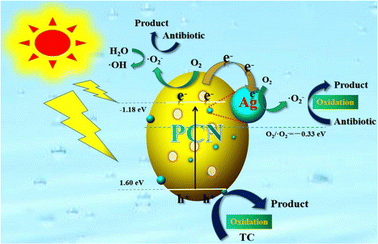 | ||
| Fig. 12 Schematic illustration of photocatalytic mechanism of the Ag/GCN plasmonic photocatalyst. Reprinted with permission from ref. 82 Copyright 2020, Elsevier. | ||
Due to its suitable band position, GCN can be combined with various photocatalyst materials to construct heterojunctions, such as Z-scheme heterojunction, promoting electron–hole separation.83 Xing et al. developed a direct Z-scheme GCN/MoS2 heterojunction by heating MoS2 nanosheets with GCN precursors and NH4Cl at 550 °C for 4 h under an Ar atmosphere, which was denoted as MCN sample.84 The authors suggested that the Mo–N bond formation is the main reason for efficient photogenerated charge carrier transfer. The formation of the Mo–N bond was confirmed by XPS characterization, in which the appearance of a new peak at 235.8 eV for the Mo 3d orbital and 401.5 eV for N 1s was observed. Fig. 13 shows the band energy alignment of the Z-scheme GCN/MoS2 heterojunction. In addition, the heterojunction fabricated with 20 mg MoS2 nanosheets, 2 g GCN, and 6 g NH4Cl, denoted as MCN-20, exhibited the highest photocatalytic degradation performance for methylene blue (100% within 60 min).
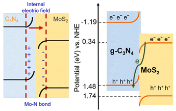 | ||
| Fig. 13 Direct Z-scheme heterojunction illustration of GCN/MoS2. Reprinted with permission from ref. 84 Copyright 2023, the American Chemical Society. | ||
A ternary GCN heterojunction consisting of magnetic carbon nanotubes (CNT), red phosphorus (RP), and graphitic carbon nitride (GCN) for visible-light photocatalytic water disinfection, namely GCN/RP/CNT, was constructed by Yang et al.85 GCN/RP/CNT was fabricated through a two-step hydrothermal process. Water disinfection studies revealed that GCN/RP/CNT exhibited broad-spectrum antibacterial activity against E. faecalis, E. coli, P. aeruginosa, and S. aureus. The outstanding performance of GCN/RP/CNT was attributed to its broad light absorption (200–800 nm) and prolonged charge carrier lifetime due to the highly-efficient charge separation.
Heterojunction construction requires careful consideration of the material selection given that it can diminish the continuity of the charge carrier transfer between semiconductors.86 Therefore, the homojunction construction of a single semiconductor may be a feasible strategy to overcome the limitations of heterojunctions. Zhang et al. synthesized a heptazine-based ordered-distorted interface by heating a mixture of cyanuric chloride with NaSCN.87 Upon heating, sulphur evaporated, forming a distorted heptazine-based structure. Also, NaCl was formed and together they formed a eutectic mixture of NaCl/LiCl system. This eutectic salt provided a suitable reaction medium to partially convert distorted heptazine into crystalline PHI, thus forming a distorted interface. The authors stated that the photogenerated electrons will spontaneously transfer due to the dual-band structure.
In the textile industry, membrane filtration is used to treat dyes before they are discharged into the environment. However, long-term usage will cause membrane fouling, thus decreasing the permeability. Recently, Imoto et al. developed a photo-induced self-cleaning membrane by forming a 2D nanosheet composite of HNb3O8/GCN heterostructure.88 The porous nature of this heterostructure allowed water to flow, while maintaining its function as a photocatalyst. The RhB degradation under UV irradiation for 4 h reached up to 90%. In addition, the permeance of the membrane decreased by around 80% using bovine serum albumin solution (BVA) as the foulant in the water permeance test. When washed in UV light, the water permeation was significantly restored to its normal condition within 2 h. The high catalytic activity of HNb3O8/GCN is attributed to the suppression of exciton recombination given that the electron in CB of GCN can quickly transfer to the CB of HNb3O8 due to their matching band position.
Chang et al. copolymerized urea with 2-aminothiophene-3-carbonitrile (ATCN), followed by polymerization under a salt melt (NaCl/KCl) condition to promote charge separation and light absorption capacity.48 They found that the composition of urea and ATCN plays a crucial role in the light absorption capacity. Simultaneously, the crystalline phase of PHI is responsible for the effective charge separation, thus increasing the photocatalytic performance by almost four times compared to the amorphous carbon nitride phase.
Chen et al. successfully prepared an S-scheme heterojunction of PTI with WO3 nanoparticles.47 They used the LiCl/KCl molten salt-assisted method with dicyanamide as the precursor. Compared to the traditional PCN, the advantage of PTI in the S-scheme heterojunction is that it provides more mobility to the photogenerated electron–hole pairs, favoring charge separation in the S-scheme heterojunction.
Growth on highly crystalline GCN is also beneficial when supporting a co-catalyst such as cobalt phosphide (CoP). Guo et al. prepared CoP-modified high-crystalline g-C3N4 and examined its performance for the degradation of tetracycline under visible light irradiation.90 The catalyst was synthesized via Ni-foam-induced thermal condensation to obtain highly crystalline g-C3N4, followed by a solvothermal route to anchor the CoP cocatalyst. The material was able to degrade 96.7% TC within 120 min due to the formation of crystalline g-C3N4, which reduced the surface defects, and the presence of CoP accelerated the photogenerated electron–hole pair separation, as illustrated in Fig. 14. Table 1 summarizes the improvement strategies of graphitic carbon nitride.
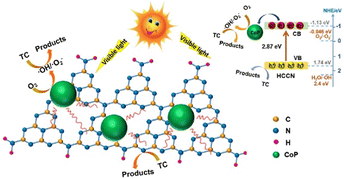 | ||
| Fig. 14 Schematic illustration of CoP-modified highly crystalline g-C3N4. Reprinted with permission from ref. 90 Copyright 2020, Elsevier. | ||
| Improvement strategies | Preparation | Dopant and/or other photocatalyst | Pollutant | Light source | Photocatalytic performance | Ref. | |
|---|---|---|---|---|---|---|---|
| Precursor | Method | ||||||
| Pore formation | Urea solution | Thermal polymerization | RhB (30 ppm) | 300 W xenon lamp, λ > 400 nm | DE = 100% | 74 | |
| t dark = 30 min | |||||||
| t light = 90 min | |||||||
| Melamine | Pre-polymerization followed by thermal polymerization | RhB (10 mg L−1) | DE = 98% | 64 | |||
| t dark = 30 min | |||||||
| t light = 15 min | |||||||
| Dicyandiamide + carbon nanotubes | Hard template thermal polymerization | DE = 58% | 76 | ||||
| t dark = 0 min | |||||||
| t light = 90 min | |||||||
| Doped GCN | Urea | Thermal polymerization followed by oxidation | O | BPA (45 μM) | 300 W xenon lamp, λ > 420 nm | DE = 99% | 78 |
| t dark = 60 min | |||||||
| t light = 120 min | |||||||
| Thermal polymerization together with ZnCl2 | Zn | MO | Solar light | DE = 81% | 79 | ||
| t dark = 0 min | |||||||
| t light = 150 min | |||||||
| Dicyandiamide + NH4Cl | Thermal polymerization | P | DCF (10 mg L−1) | 9 W LED light (410 < λ < 530 nm) | DE = 99.4% | 81 | |
| t dark = 0 min | |||||||
| t light = 40 min | |||||||
| Melamine + hexachlorotriphosphazene (HCPP) | P | MB (5 ppm) | 300 W xenon lamp | DE = 90% | 73 | ||
| t dark = 60 min | |||||||
| t light = 120 min | |||||||
| Urea + melamine | K and Cl | TC (20 ppm) | 6 W LED (λ > 365 nm) | DE = 75% | 80 | ||
| t dark = 50 min | |||||||
| t light = 180 min | |||||||
| Plasmonic nanocomposite | Dicyandiamide + NH4Cl | Thermal polymerization | Au NPs and 2D Ti3C2 | Cefixime (0.05 mM) | 2 × 45 W CFL lamps | DE = 65% | 71 |
| t dark = 0 min | |||||||
| t light = 105 min | |||||||
| Melamine | Thermal polymerization followed by post-heating | Ag NPs | TC (20 mg L−1) | 300 W xenon lamp, λ > 420 nm | DE = 83% | 82 | |
| t dark = 0 min | |||||||
| t light = 120 min | |||||||
| Heterojunction | Melamine + NH4Cl | Pyrolysis under Ar atmosphere | MoS2 | MB (20 ppm) | 300 W xenon lamp (AM 1.5 filter) | DE = 100% | 84 |
| t dark = 0 min | |||||||
| t light = 60 min | |||||||
| Urea | Thermal polymerization | Red phosphorus and carbon nanotubes | S. aureus (107 cfu mL−1) | 300 W xenon lamp, λ > 400 nm | DE = 100% | 85 | |
| t dark = 0 min | |||||||
| t light = 90 min | |||||||
| Dicyandiamide | Thermal polymerization followed by thermal exfoliation | HNb3O6 | RhB (50 ppm) | UV lamp | DE = 90% | 88 | |
| t dark = 0 min | |||||||
| t light = 240 min | |||||||
| Urea | Thermal polymerization followed by ultrasonic exfoliation | Chitosan | MB | Solar light | DE = 90% | 91 | |
| t dark = 0 min | |||||||
| t light = 40 min | |||||||
3. Graphene and its derivatives as nanocomposite photocatalysts
Photocatalytic technology has made significant progress in several applications, particularly in the remediation of water waste.25 Nevertheless, this technology still has severe drawbacks, including the inability to work with visible light, rapid recombination capability, and the tendency to create aggregates.78,92 Photocatalytic technology, in general, works with UV rays due to their large band gap, preventing them from operating in the visible light range.93 As a result of this phenomenon, the costs significantly increase because artificial UV sources must be provided, given that the UV radiation from the sun accounts for no more than 5% of the total emitted radiation.94 Furthermore, the photocatalysis process produces fewer hydroxyl radicals due to the short recombination time and aggregation phenomena, leading to the reduced photon efficiency of the catalyst.95,96 Thus, to address these challenges, researchers have been developing photocatalysis using carbon-based materials, graphene, and its derivatives. They feature unique qualities because of their smaller bandgap, conductivity, high specific surface area, and chemically stable surface. It is worth noting that these graphene-based materials cannot be excited by photoirradiation to generate electrons and holes to drive redox reactions. Instead, they can act as an electron transfer medium to prolong the recombination time, modify the bandgap energy levels of photocatalysts to improve their performance under visible light exposure, and control the size and morphology of photocatalysts to prevent their agglomeration.43,96–993.1. General properties of graphene and its derivatives
Graphene is a one-atom-thick two-dimensional nanomaterial consisting of carbon atoms organized in a hexagonal pattern, as shown in Fig. 15. Due to the high electrical conductivity (200 S m−1) and large surface area (2630 m2 g−1 for a single graphene sheet) of graphene, it has been successfully employed in photocatalytic applications mainly as an electron mediator and photocatalyst support.100 Graphene oxide (GO) and reduced graphene oxide (rGO) are the two extensively utilized graphene derivatives, as can be seen in Fig. 15. Graphene oxide (GO) formed by the oxidation of graphite possesses functional groups including hydroxyl, alkoxy, epoxy, carbonyl, and carboxyl. However, the high electrical resistivity of GO (1.64 × 10⁴ Ωm)101 leads to development of rGO, which is formed by removing oxygen functional groups from the GO structure.3.2. Synthesis of graphene and its derivatives
 | ||
| Fig. 16 (a) Illustration of the mechanical exfoliation with the Scotch tape method. (b) Illustration of liquid-phase exfoliation. Reprinted with permission from ref. 105 Copyright 2021, Springer Nature. | ||
In bottom-up processes, the most applied method is chemical vapor deposition (CVD), which is carried out at high temperatures (∼1000 °C) on transition metals (such as Cu, Co, and Fe), while being exposed to low-concentration hydrocarbon gas to fill the surface with carbon atoms. Methane gas serves as the carbon source in this method, while H2 and Ar function as reaction stabilizers to improve the uniformity of the formed layer, as shown in Fig. 17. However, although this method can produce high-quality graphene suitable for mass production, it is less efficient in terms of manufacturing processes and costs.106
 | ||
| Fig. 17 Illustration of the chemical vapor deposition (CVD) to synthesize graphene. Reprinted with permission from ref. 106 Copyright 2021, Nature. | ||
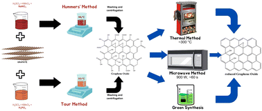
However, although the Hummers’ method is a safer and faster synthesis process, it still produces toxic gas as a by-product. Therefore, another method has been developed, namely the Tour method, which replaces sodium nitrate with phosphoric acid as the dispersing and etching agent. The Tour method produces graphene oxide with a higher level of oxidation, does not release toxic gas, and is conducted at a low temperature (∼50 °C).104
Furthermore, the microwave method has attracted significant attention for the GO reduction process, which has the ability to provide uniform heating in a short period of time.110 Nevertheless, this method needs to be operated under inert conditions or with the addition of reducing agents such as NaBH4 to achieve significant reduction capabilities.111 These issues have prompted research on the synthesis of rGO using sources derived from nature, which is commonly known as green synthesis.104 In general, the green synthesis process occurs through the reaction between dispersed GO solution and a green reducing agent with a specific duration and at a controlled temperature. However, this method is still in its developmental stage because it results in the formation of aggregates and by-products, hence requiring additional agents that act as stabilisers.104,112Fig. 18 depicts the process of synthesizing graphene and its derivatives.
3.3. Photocatalysis mechanism of graphene-based nanocomposites
Some frequently used photocatalysts are TiO2 and ZnO,17,92,113 both of which are semiconductor-based photocatalysts that have high oxidation and degradation capabilities for organic components, low cost, and good chemical and thermal stability.18 However, these two materials still have some drawbacks, including the possibility of metal toxicity, large band gap, fast recombination time, and the possibility to form aggregates.3 These drawbacks can be addressed by creating a composite material between a photocatalytic semiconductor material and other components that improve its performance.Graphene and its derivatives have been employed to tackle the above-mentioned limitations due to the following reasons: (a) graphene has a specific surface area of 2630 m2 g−1, a hexagonal arrangement of σ-bonded atoms, and a unique orbital surface structure, which make it capable of enhancing the overall surface area of composite systems.100,114 (b) Graphene has high electron conductivity, making it suitable as an electron conductor in heterojunctions. (c) Additionally, the interaction between the energy levels of the semiconductor bands and graphene can modulate the band structure in the composite. Consequently, the photocatalyst may be stimulated by visible light, enhancing its effectiveness in absorbing light and preventing aggregation.115
The construction of a Z-scheme heterojunction is the most commonly employed method in the application of graphene as a photocatalyst support. Upon the combination of a semiconductor and graphene, efficient electron transfer process occurs. When irradiated with light, the electron from the VB of the semiconductor jumps to the CB of the semiconductor, and subsequently transferred to the graphene layer, thus prolonging the charge carrier lifetime, as shown in Fig. 19a. Moreover, ternary nanocomposites can also be fabricated by integrating two semiconductors with graphene. Upon irradiation, electrons from both semiconductors are excited from the VB to the CB of each semiconductor and will be injected to the graphene materials, as shown in Fig. 19b. After that, the excited electrons from the CB of PS I reduce dissolved oxygen to superoxide radicals, while the excited electrons in the CB of PS II migrate to the CB of carbon nanomaterials (CNM), and then to the VB of PS I given that they cannot reduce oxygen to O2˙−. The holes in the VB of PS II can oxidize adsorbed H2O molecules to form hydroxyl radicals (OH˙), which then attack the absorbed pollutants to form non-harmful products. In this scheme, CNM serves to facilitate the separation and recycling of the photocatalyst and acts as an electron transfer channel.95,116,117
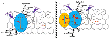 | ||
| Fig. 19 (a) Illustration of the mechanism of binary-based rGO/TiO2 as a photocatalyst. (b) Illustration of the mechanism of ternary Z-scheme heterojunction ZnO/rGO/TiO2. | ||
3.4 Photocatalysis roles of graphene-based nanocomposites
3.4.1.1. Graphene. An experiment was performed in which graphene was used as a substrate for the formation of TiO2 crystals. Subsequently, the framework was modified with phenyl groups, which acted as building blocks to create ultrathin polymer layers on the surface of TiO2. The resultant composite, referred to as PTG (polymer-TiO2/graphene), possessed an exceptional surface area of 988 m2 g−1, which was 8-times greater than its counterpart, graphene–TiO2. The experiment aimed to evaluate the photocatalytic efficacy of PTG and TiO2 in the degradation of sulfadiazine (SDZ) molecules. PTG has a substantially greater degradation kinetic constant (0.0763 min−1) than that of TiO2 (0.0295 min−1) under visible light irradiation.’The substantial surface area of graphene enables it to serve as an electron mediator, promoting the separation of electrons and holes. Consequently, the degradation rate of SDZ is enhanced, as seen in Fig. 20a.120
 | ||
| Fig. 20 (a) Illustration of the adsorption and degradation process of sulfadiazine under visible light spectrum using polymer-TiO2–graphene. Reprinted with permission from ref. 120 Copyright 2022, Elsevier. (b) Charge transfer mechanism during the photodegradation of TC over nanocomposites under visible light irradiation. Reprinted with permission from ref. 122 Copyright 2023, Elsevier. | ||
Another experiment used the hydrothermal technique and chemical vapor deposition approach to effectively manufacture a composite-based photocatalyst, diatomite@graphene@ZnO (ZGD), for the degradation of methylene blue (MB) dye. The Langmuir–Hinshelwood model was used to analyze the ZnO and ZGD samples, with MB degradation rates of 0.05109 min−1 and 0.06638 min−1, respectively. In addition, the photoluminescence (PL) analysis revealed a prominent emission peak at 442 nm, which arises from the recombination of electrons and holes during the band-to-band transition. The photoluminescence (PL) spectrum demonstrated a substantial decrease in intensity for ZGD, indicating its ability to suppress the recombination of charge carriers caused by light and improve the photocatalytic degradation efficiency of ZnO. Therefore, the existence of graphene can function as an intermediary for electrons, impeding the recombination process and leading to the heightened generation of free radicals, which are responsible for breaking down MB, improving the degradation efficiency of MB.121
Another experiment successfully produced a nanocomposite consisting of molybdenum sulfide (MoS2) associated with graphene (G) and iron oxide (Fe2O3) using the hydrothermal process. This nanocomposite was utilized to degrade tetracycline (TC) molecules when exposed to visible light. Four materials were subjected to PL testing, namely Fe2O3, MoS2, MoS2/Fe2O3 (MF), and MoS2/Fe2O3/G (MFG). The results demonstrated that the PL spectrum intensity of the MFG nanocomposite exhibited the lowest efficacy, indicating the more rapid charge separation of photo-induced electron–hole pairs. This suggests that the inclusion of graphene can function as an intermediary for electrons, as seen in Fig. 20b.122
3.4.1.2. Graphene oxide (GO). A successful research project was the synthesis of a Z-scheme heterojunction, namely 15% AgBr/5GO/Bi2WO6 (referred to as 15A/5G/BW), utilizing the hydrothermal and in situ deposition methods. The results demonstrated an impressive degradation efficiency of 84% under visible light illumination, with a kinetic rate of 0.0515 min−1, which is equivalent to 3.16- and 4.60-times that of Bi2WO6 and AgBr, respectively. Furthermore, the photoluminescence (PL) analysis revealed that the lowest PL intensity was observed for 15A/5G/BW. This phenomenon indicates that the heterojunction composite material 15A/5G/BW contributes to the prevention of the recombination process.123
Another study showed the synthesis of a BiVO4/BiPO4/GO photocatalyst capable of decomposing RB-19 dye molecules by 99% using visible light within 60 min. The average photocatalysis rate of this process was 4.9-times higher than BiVO4 and 31.5 times faster than BiPO4. In addition, the incorporation of GO in this photocatalyst material improved the charge transfer processes and efficiently formed a heterojunction between BiVO4 and BiPO4, effectively inhibiting charge recombination.124
Another investigation demonstrated the production of a photocatalyst called g-C3N4/GO/BiFeO3 (CNGB) for reducing Cr(VI) waste using visible light. The CNGB photocatalyst was fabricated using three different ratios of GCN and BiFeO3 (2![[thin space (1/6-em)]](https://www.rsc.org/images/entities/char_2009.gif) :
:![[thin space (1/6-em)]](https://www.rsc.org/images/entities/char_2009.gif) 4, 3
4, 3![[thin space (1/6-em)]](https://www.rsc.org/images/entities/char_2009.gif) :
:![[thin space (1/6-em)]](https://www.rsc.org/images/entities/char_2009.gif) 3, and 4
3, and 4![[thin space (1/6-em)]](https://www.rsc.org/images/entities/char_2009.gif) :
:![[thin space (1/6-em)]](https://www.rsc.org/images/entities/char_2009.gif) 2). These ratios demonstrated exceptional effectiveness in decomposing Cr(VI) ions within 90 min. Moreover, the experimental findings demonstrated consistent and reliable recyclability performance for CNGB over three cycles. Photoluminescence data was gathered to evaluate the capacity of this material to impede the recombination process, while photocurrent data was obtained to ascertain the quantity of electrons produced. The test findings showed that g-C3N4/GO/BiFeO3 (CNGB) exhibited the lowest intensity in photoluminescence analysis and the greatest value of photocurrent density. This suggests that the inclusion of GO can impede the recombination process, resulting in the production of a greater number of free radicals. Furthermore, Fig. 21 illustrates the process of electron transfer and photoreduction of Cr(IV).125
2). These ratios demonstrated exceptional effectiveness in decomposing Cr(VI) ions within 90 min. Moreover, the experimental findings demonstrated consistent and reliable recyclability performance for CNGB over three cycles. Photoluminescence data was gathered to evaluate the capacity of this material to impede the recombination process, while photocurrent data was obtained to ascertain the quantity of electrons produced. The test findings showed that g-C3N4/GO/BiFeO3 (CNGB) exhibited the lowest intensity in photoluminescence analysis and the greatest value of photocurrent density. This suggests that the inclusion of GO can impede the recombination process, resulting in the production of a greater number of free radicals. Furthermore, Fig. 21 illustrates the process of electron transfer and photoreduction of Cr(IV).125
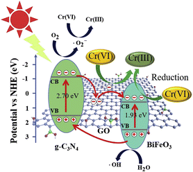 | ||
| Fig. 21 Illustration of the potential process for the photoreduction of Cr(VI) over the CNGB-2 heterojunction when exposed to visible light. Reprinted with permission from ref. 125 Copyright 2019, Elsevier. | ||
3.4.1.3. Reduced graphene oxide (rGO). A study involves the preparation of TiO2 photocatalytic composites with the addition of conductive materials. The rGO material has a high conductivity value of 1180 S m−1,126 which prolongs the recombination time of the photocatalyst. In this study, the photoluminescence test graph, as can be seen in Fig. 22a, showed a broad and narrow peak at λ = 500 nm, which was only observed in the samples containing TiO2, indicating the relation of this peak with defects in TiO2. The addition of rGO increased the recombination time to 2.91 ns from 2.05 ns and the photocatalytic activity of TiO2 for synthetic dye degradation was 30.6%, which increased to 82.9% with the TiO2/rGO material, as shown in Fig. 22b.43
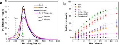 | ||
| Fig. 22 (a) PL spectra and (b) photocatalytic performance of the TiO2/rGO nanocomposite. Reprinted with permission from ref. 43 Copyright 2021, the American Chemical Society. | ||
Another experiment successfully synthesized a ternary photocatalyst called rGO/Fe3O4/ZnO (GFZ) for the degradation of metalaxyl waste under the visible light spectrum. The performance testing data was collected with several fixed parameters, including pH 7, catalyst loading of 25%, catalyst concentration of 0.5 g L−1, metalaxyl concentration of 10 ppm, and light intensity of 20![[thin space (1/6-em)]](https://www.rsc.org/images/entities/char_2009.gif) 000 lux. The testing results showed a maximum degradation percentage of 92.11% using the GFZ photocatalyst, which operated under the visible light spectrum for 120 min and was able to work consistently for up to 5 cycles. In the subsequent cycle, the degradation percentage reached 88.12%. Furthermore, the photoluminescence analysis revealed that GFZ has the lowest intensity (∼150) compared to ZnO and ZnO/Fe3O4, which indicates the formation of oxygen defects during the reduction of GO, acting as electron mediators and inhibiting the recombination process.127
000 lux. The testing results showed a maximum degradation percentage of 92.11% using the GFZ photocatalyst, which operated under the visible light spectrum for 120 min and was able to work consistently for up to 5 cycles. In the subsequent cycle, the degradation percentage reached 88.12%. Furthermore, the photoluminescence analysis revealed that GFZ has the lowest intensity (∼150) compared to ZnO and ZnO/Fe3O4, which indicates the formation of oxygen defects during the reduction of GO, acting as electron mediators and inhibiting the recombination process.127
The fabrication of a heterojunction photocatalyst, Ag2O/ZnO/rGO, using a microwave hydrothermal method to decompose BPA waste was successfully conducted. The research revealed that the optimal ratio of 5% Ag and 3% rGO exhibited a photocatalytic efficiency of 80%, which is three-times higher than pure ZnO under simulated sunlight. Moreover, this ratio demonstrated significantly improved stability, retaining nearly 80% of its efficiency after five cycles. Furthermore, when photoluminescence testing was performed, a low intensity was obtained for 5%-Ag2O/ZnO/rGO-3 wt%, which indicates the addition of rGO can act as an electron mediator due to its ability to inhibit the electron and hole recombination processes.128
In another strategy, the WO3/CuO/rGO nanocomposite was synthesized for the degradation of different pollutants such as methylene blue (MB), rhodamine B (RhB), and benzoic acid. The highest degradation percentages for all three pollutants were found for the WO3/CuO/rGO nanocomposite, with MB degradation reaching 95.5%, RhB degradation at 93.1%, and benzoic acid degradation at 91.8% within 90 min of UV radiation. It appears that due to the formation of heterojunction interfaces between individual components, WO3/CuO/rGO demonstrated the highest capability for pollutant degradation in each experiment. Additionally, a comparison of the rate constants for the three pollutants among four different materials (CuO, WO3, CuO/WO3, and WO3/CuO/rGO) revealed that WO3/CuO/rGO exhibited the highest degradation rates of 0.028 min−1 for MB, 0.027 min−1 for RhB, and 0.024 min−1 for benzoic acid. These results indicate that the use of rGO can function as an electron mediator, enhancing the degradation rates of MB, RhB, and benzoic acid.129
3.4.2.1. Graphene. A study successfully synthesized the Fe2O3/G/CuO nanocomposite material (FGC) using a simple solvothermal method. This study aimed to increase the bandgap of CuO, which is 1.2 eV. The low bandgap of CuO allows the CuO photocatalyst to operate in the visible light region. However, the energy level in the CuO conduction band is more positive than the hydrogen reduction potential, leading to rapid recombination. Therefore, the addition of Fe2O3 to graphene is necessary to lower the energy level of the conduction band of the photocatalyst, while maintaining a bandgap energy value that is not too large to ensure high photocatalytic performance in the visible light spectrum. The research results indicated a bandgap energy of 1.49 eV with a degradation percentage of 94.27% for MB using visible light irradiation for 40 min.130
Another study reported the successful synthesis of TiO2/graphene through a hydrothermal method using TiCl4 as a precursor. One goal of this study was to find out how changes in the concentration of TiO2 and the addition of graphene affect the reduction of the bandgap energy of the photocatalyst. The six sample variations investigated in this study were TiO2, 5%-TiO2/G, 21.5%-TiO2/G, 36.5%-TiO2/G, 74.5%-TiO2/G, and 84%-TiO2/G. Experiments were performed using diffuse reflectance UV-vis spectroscopy (DRS UV-vis) to determine the bandgap energy values. The measurement results showed bandgap energy values of 3.30 eV for TiO2, 2.63 eV for 5%-TiO2/G, 2.88 eV for 21.5%-TiO2/G, 3.09 eV for 36.5%-TiO2/G, 3.29 eV for 74.5%-TiO2/G, and 3.35 eV for 84%-TiO2/G, as can be seen in Fig. 23. This indicates that as the graphene concentration increased, the bandgap energy decreased, enabling the photocatalyst to operate in the visible light spectrum.131
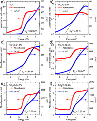 | ||
| Fig. 23 UV-vis diffuse reflectance spectra and related Tauc plots of TiO2 (a) and TiO2/graphene with varying TiO2 loadings (5% (b), 21,5 (c), 36,5% (d), 74,5% (e), and 84% (f)). Reprinted with permission from ref. 131 Copyright 2021, Elsevier. | ||
3.4.2.2. Graphene oxide (GO). An experiment was conducted involving the synthesis of AgBr/GO/Bi2WO6, and it was revealed that the inclusion of GO resulted in a reduction in the bandgap energy. This reduction allowed the photocatalyst to efficiently function within the visible light spectrum. Three sample variants were examined to observe the effect of adding GO on the bandgap energy, namely AgBr, GO/Bi2WO6, and AgBr/GO/Bi2WO6. The findings indicated that the AgBr/GO/Bi2WO6 material exhibited the lowest bandgap energy value of around 2 eV, which is considerably lower than that of AgBr of around 2.6 eV. This discovery suggests that the inclusion of GO was successful in decreasing the bandgap energy, hence improving the photocatalytic efficiency within the visible light range.123
Another study successfully synthesised the TiO2/GO/CuFe2O4 nanocomposite using the ball milling method. One aim of this study was to assess the impact of incorporating GO on the decrease in bandgap energy. Applying the Kubelka–Munk equation to the measurements performed using DRS UV-vis showed that the TiO2/GO/CuFe2O4 nanocomposite has a bandgap energy of 2.40 eV. This value is notably lower than that of TiO2, which has a bandgap energy of 3.2 eV. Hence, our work suggests that the incorporation of GO can significantly decrease the bandgap energy of the photocatalyst. Moreover, the mechanism of photocatalyst reaction can be seen in Fig. 24.132
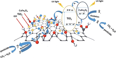 | ||
| Fig. 24 Proposed mechanism describing the process of charge separation in TiO2/GO/CuFe2O4 through a direct Z-type scheme when exposed to UV light. Reprinted with permission from ref. 132 Copyright 2020, The Royal Society of Chemistry. | ||
3.4.2.3. Reduced graphene oxide (rGO). Having a large surface area, abundant functional groups, and a rich π-conjugated system, graphene-based materials can enhance the photocatalytic activity of the main photocatalyst by preventing its aggregation, broadening its light absorption, and promoting pollutant adsorption.133 An experiment showed that the addition of rGO to TiO2 can shift the light absorption of TiO2 towards the visible light region.134 The shifting of TiO2 light absorption properties is due to the formation of a Ti–O–C bond, which alters the valence band value of TiO2, hence narrowing the overall bandgap of TiO2.135 In addition, DR UV-vis characterization showed that the addition of 15% rGO to TiO2 achieved the highest visible light absorption and the narrowest bandgap. Furthermore, the characterization using diffuse reflectance ultraviolet-visible (DR UV-vis) revealed that the addition of 15% rGO to TiO2 could reduce the bandgap energy from 3.15 eV to 2.73 eV. The decrease in the bandgap energy value due to the introduction of rGO further strengthened the effectiveness of the photocatalytic performance when operating under visible light irradiation.
An investigation successfully synthesized a CdSe/rGO photocatalyst using the sol–gel method to degrade thiophene with varying concentrations of rGO up to 20%. The test results revealed that the addition of 15% rGO caused a reduction in the bandgap of pure CdSe from 2.3 eV to 1.78 eV, leading to an enhancement in its visible light absorption, as shown in Fig. 25a. Also, photoluminescence tests (shown in Fig. 25b) showed that the peak wavelength shifted to the right, which indicates that the bandgap energy changed when rGO was added. Photocurrent testing confirmed these findings, showing an increase in electron charge production. Both analyses suggest that the addition of rGO can inhibit the recombination process and broaden the spectrum of light absorption to include visible light.136
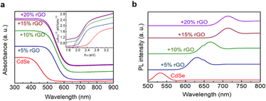 | ||
| Fig. 25 (a) DR UV-vis spectra of the CdSe/rGO sample and (b) PL spectra of the CdSe/rGO. Reprinted with permission from ref. 136 Copyright 2020, Elsevier. | ||
3.4.3.1. Graphene. In addition to improving the light absorption characteristics of the photocatalyst, graphene also plays a crucial role in avoiding aggregation and enhancing the surface area. For example, an experiment successfully controlled the growth of TiO2 using TiCl4 as the precursor and addition of graphene using the hydrothermal method. The size of the TiO2 particle is a function of precursor concentration and reaction time, and when both variable increased, the size of TiO2 also increased. In this work, the smallest TiO2 particle size achieved was 4.9 nm, which is smaller than the commercial P25 TiO2. The ability of graphene to control the size of TiO2 is due to the hydroxyl (–OH) functionalization of graphene. TiCl4 can react to grow nuclei during the hydrothermal process. Hence, graphene with rich OH group tends to produce small TiO2 particles. Furthermore, this research also demonstrates a comparison of the degradation abilities of TiO2, graphene, and TiO2/graphene with a TiO2 concentration of 25% towards rhodamine blue waste, and the results show that the TiO2/graphene material provides the highest degradation performance. This indicates that the addition of a conductive material in the form of graphene can enhance the photocatalytic activity for degrading rhodamine blue waste.131
3.4.3.2. Graphene oxide (GO). An experiment successfully synthesized a photocatalyst by combining the TiO2 material with conductive materials based on GO, resulting in GO–TiO2 photocatalysts, which were evaluated for their degradation performance in the presence of methylene blue and eosin Y waste under UV and white light.137 According to the research findings, the bandgap value observed was 2.8 eV in GO–TiO2. Furthermore, the maximum degradation performance for methylene blue and Eosin Y using GO–TiO2 under white light was 52% and under UV light was 75%. The increase in degradation percentage occurred due to the presence of GO, which effectively reduced the bandgap value and inhibited charge recombination.
Another study demonstrated that the addition of GO to the Cs2AgBiI6 photocatalyst could weaken the potential for agglomeration. As shown in Fig. 26a, the SEM test results for the Cs2AgBiI6 material indicate significant agglomeration of the material, which requires handling to enhance its photocatalytic activity. The addition of GO to the material, as shown in Fig. 26b, resulted in the uniform dispersion of Cs2AgBiI6 on the surface of GO, and the agglomeration phenomenon appeared to be weakened compared to in the absence of GO.138
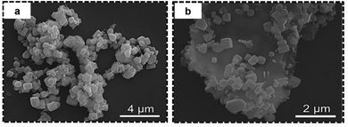 | ||
| Fig. 26 SEM image of (a) Cs2AgBiI6 showing agglomerated particles and (b) GO/Cs2AgBiI6 showing less agglomerated particles. Reprinted with permission from ref. 138 Copyright 2023, Elsevier. | ||
3.4.3.3. Reduced graphene oxide (rGO). One study successfully created a visible-light-responsive composite, namely PANI/rGO/MnO2, which exhibited photocatalytic activity for degrading methylene blue by 90% under visible light for 2 h. This is attributed to the reduction in the bandgap of this three-component composite, resulting in a broader range of light absorption. Additionally, SEM testing was conducted on four sample variations, i.e., PANI, MnO2, PANI/MnO2, and PANI-rGO-MnO2. The presence of rGO in the PANI–MnO2 composite also demonstrated its ability to prevent the aggregation of materials.139 Moreover, a schematic illustration of the photocatalytic reduction of MB is presented in Fig. 27a.
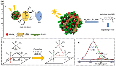 | ||
| Fig. 27 (a) Schematic illustration of the photocatalytic reduction of MB. Reprinted with permission from ref. 139 Copyright 2019, Elsevier. (b) Illustration of the mechanism of TiO2 on the surface of GO sheet. (c) XPS spectra of TiO2–graphene. Reprinted with permission from ref. 140 Copyright 2020, Elsevier. | ||
Another experiment successfully synthesised rGO/TiO2 composites and showed that the addition of rGO could prevent the agglomeration of TiO2 due to the huge surface area of the graphene sheets, which provided an appropriate surface for the distribution of the TiO2 NPs.140 The hindered agglomeration is attributed to the connection between TiO2 and oxygen-containing functional groups, which are consistently spread throughout the GO surface, as shown in Fig. 27b. This hypothesis is supported by the XPS data, in which the appearance of an additional peak of C 1s at 285.8 eV in rGO/TiO2 is attributed to the C–O–Ti bond, as shown in Fig. 27c.140Table 2 summarizes the developments of graphene-based nanocomposites and its derivatives in photocatalytic wastewater treatment.
| Type of composite | Carbon-based material | Photocatalyst material | Method | Pollutant | Light source | Photocatalytic performance | Ref. |
|---|---|---|---|---|---|---|---|
| Binary composite | Graphene | Graphene/TiO2 | Hydrothermal | Rhodamine blue | Tungsten filament light bulb, 60 W | DE = 21.5% | 131 |
| t dark = 2.5 h | |||||||
| t light = 6 h | |||||||
| Graphene/(Polymer-TiO2) | TiO2/graphene: co-precipitation | Sulfadiazine | Xenon lamp, 300 W, 420 nm | DE = 98.4% | 120 | ||
| Polymer/TiO2/graphene: hypercrosslinked | t dark = 40 min | ||||||
| t light = 40 min | |||||||
| GO | GO/TiO2 | GO: Hummer's | Methylene blue | Violet lamp, 125 W | DE = 52% | 137 | |
| t dark = 60 min | |||||||
| t light = 360 min | |||||||
| GO/TiO2: Thermal | Eosin Y | White light, 40 W | DE = 24.2% | ||||
| t dark = 60 min | |||||||
| t light = 360 min | |||||||
| GO/Cs2AgBiI6 | Cs2AgBiI6: Antisolvent recrystallization | Sudan Red III toluene | Xenon lamp, 300 W, 420 nm | DE = 85% | 138 | ||
| GO: Hummer | t dark = 30 min | ||||||
| t light = 100 min | |||||||
| rGO | rGO/TiO2 | Thermal | Methylene blue | Violet lamp, 125 W | DE = 95% | 137 | |
| t dark = 60 min | |||||||
| t light = 360 min | |||||||
| Eosin Y | White light, 40 W | DE = 37% | |||||
| t dark = 60 min | |||||||
| t light = 360 min | |||||||
| rGO/TiO2 | rGO: Tour | Rhodamine 6G | UV lamp, 52 nm | DE = 82.9% | 43 | ||
| rGO/TiO2: Microwave-assisted method | t dark = 0 min | ||||||
| t light = 240 min | |||||||
| rGO/TiO2 | Hydrothermal | Methylene blue | UV Hitachi lamp, 2 ×8 W | DE = 90% | 140 | ||
| t dark = 60 min | |||||||
| t light = 180 min | |||||||
| rGO/TiO2 | Hydrothermal | Methylene blue | Osram's Ultra Vitalux lamp | DE = 99.6% | 134 | ||
| t dark = 60 min | |||||||
| t light = 120 min | |||||||
| Rhodamine blue | DE = 99.9% | ||||||
| t dark = 60 min | |||||||
| t light = 120 min | |||||||
| rGO/CdSe | CdSe: Sol–gel | Thiophene | Medium pressure mercury lamp, 125 W, 420 nm | DE = 100% | 136 | ||
| t dark = 0 min | |||||||
| rGO/CdSe: Ultrasonication | t light = 90 min | ||||||
| Ternary composite | G | Graphene/ZnO/diatomite | Hydrothermal | Methylene blue | UV lamp, 10 W | DE = 100% | 121 |
| t dark = 10 min | |||||||
| t light = 90 min | |||||||
| Graphene/MoS2/Fe2O3 | Hydrothermal | Tetracycline | Xenon lamp, 350 W | DE = 96.6% | 122 | ||
| t dark = 20 min | |||||||
| t light = 140 min | |||||||
| Graphene/Fe2O3/CuO | Solvothermal | Methylene blue | Various lamp, Various W 40 W, 60 W, 100 W, and 130 W | DE = 94.27% | 130 | ||
| t dark = 2 h | |||||||
| t light = 180 min | |||||||
| GO | GO/AgBr/Bi2WO6 | AgBr/GO: Hydrothermal | Tetracycline hydrochloride | Xenon lamp, 420 nm | DE = 84% | 123 | |
| t dark = 30 min | |||||||
| AgBr/GO/Bi2WO6: in situ deposition | |||||||
| t light = 60 min | |||||||
| GO/BiVO4/BiPO4 | Hydrothermal | Reactive blue 19 | Xenon lamp | DE = 99% | 124 | ||
| t dark = 30 min | |||||||
| t light = 60 min | |||||||
| GO/GCN/BiFeO3 | GCN: Calcination | Cr(VI) | Xenon lamp, 300 W, 400 nm | DE = 100% | 125 | ||
| GO: Hummer | t dark = 60 min | ||||||
| BiFeO3: Sol–gel | t light = 90 min | ||||||
| GCN/GO/BiFeO3: Methanol assisted | |||||||
| GO/TiO2/CuFe2O4 | Ball-milling | 17 different chlorinated pesticides | Xenon lamp, 150 W, 365 nm | DE = 96.5% (DDE) | 132 | ||
| t dark = 20 min | |||||||
| t light = 20 min | |||||||
| rGO | GO/Fe3O4/ZnO | Thermal co-precipitation | Metalaxyl | Led lamps, 5× 3W, 450 nm | DE = 92.11% | 127 | |
| t dark = 0 min | |||||||
| t light = 120 min | |||||||
| rGO/Ag2O/ZnO | Microwave hydrothermal | Bisphenol A | Xenon lamp, 500 W | DE = 80% | 128 | ||
| t dark = 30 min | |||||||
| t light = 180 min | |||||||
| rGO/PANI/MnO2 | In situ oxidative polymerization | Methylene blue | Halogen bulb (CL-150), 150 W | DE = 90% | 139 | ||
| t dark = 30 min | |||||||
| t light = 120 min | |||||||
| rGO/WO3/CuO | Ultrasonication | Methylene blue | Low pressure bulb, 200 W | DE = 95.5% | 129 | ||
| t dark = 60 min | |||||||
| t light = 90 min | |||||||
| Rhodamine blue | DE = 93.1% | ||||||
| t dark = 60 min | |||||||
| t light = 90 min | |||||||
| Benzoic acid | DE = 16.5% | ||||||
| t dark = 60 min | |||||||
| t light = 90 min |
4. Conclusions and future perspectives
Carbon nitride- and graphene-based photocatalysts have successfully shown extraordinary properties for the application of photocatalytic pollutant degradation either as an active material or as a nanocomposite-based material. GCN as an active carbon-based photocatalyst material has prompted researchers to conduct intensive research on exploiting more of its properties and discovered many ways to modify pristine GCN. The wide availability, facile synthesis method, and various modification possibilities including pore formation, heteroatom doping, plasmonic and heterojunction nanocomposite, and crystalline GCN make GCN very attractive in the field of photocatalytic wastewater treatment. In the future, biomass-derived GCN may be one way to synthesize GCN given that it supports the utilization of biomass.133 Another future direction is the preparation of highly crystalline GCN, which is a relatively new research field that still needs comprehensive study to discover more unique properties of GCN. In its powder form, GCN will sink when applied in wastewater and the process of material recovery will be tedious. Therefore, a floating photocatalyst using GCN may solve this limitation and be one of the future directions for GCN photocatalysts. Additionally, floating photocatalysts will increase the visible light utilization given that they can avoid light attenuation. In terms of applications, GCN can be combined with conventional membrane technology on an industrial scale in which GCN can help in reducing membrane fouling by the photocatalytic cleaning process.88 Given that wastewater may contain bacteria, GCN can also be combined with natural polymers such as chitosan, forming a nanocomposite for treating bacteria-contaminated wastewater given that chitosan has remarkable antibacterial properties and GCN can eliminate bacteria through the photocatalytic mechanism.91,141 Furthermore, the degradation of insoluble pollutants such as low-density polyethylene (LDPE) plastic using GCN is becoming possible as stated by a recent study.142Furthermore, graphene and its derivatives play a role as supporting materials due to their extraordinary conductivity, large surface area, ability to modify bandgaps, and capacity to act as electron mediators, which are beneficial for enhancing the photocatalytic activity of the main photocatalyst. 2D carbon-based materials such as graphene, graphene oxide, and reduced graphene oxide have enabled the development of various nanocomposites by combining these materials with metals, oxides, and sensitizers to create binary or ternary nanocomposites that can enhance photocatalytic activity through the promotion of electron–hole separation and broadening the visible light absorption capacity. In the future, comprehensive studies on safer and environmentally friendly methods for the synthesis of graphene and its derivatives, such as the development of the Tour method and the potential use of nature-based materials for synthesizing or reducing graphene and its derivatives, are still necessary. Additionally, the development of using graphene-based materials to enhance the photocatalytic performance in the visible light spectrum, such as combining methods with adsorption techniques or integrating them with other photocatalytic materials, still needs to be explored.
Author contributions
I. J. B.: writing – original draft, methodology, editing; V. A. D.: writing – original draft, methodology; R. R.: writing – original draft, methodology; H. J.: methodology, writing – review; C. H.: supervision, methodology, writing – review; A. W.: conceptualization, methodology, funding acquisition, project administration, resources, supervision, writing – review. All authors have given approval to the final version of the manuscript.Conflicts of interest
There are no conflicts to declare.Acknowledgements
A. W. would like to acknowledge the ITB Research Fund 2022 scheme from the Institut Teknologi Bandung (FTMD.PN-6-02-2022). R. R. is grateful for the scholarship from The Indonesian Education Scholarship Program (BPI), Indonesian Ministry of Education, Culture, Research and Technology (00974/J5.2.3./BPI.06/9/2022).Notes and references
- L. Lin, H. Yang and X. Xu, Front. Environ. Sci., 2022, 10, 880246 CrossRef.
- WHO and UNICEF, Progress on household drinking water, sanitation and hygiene 2000-2020: five years into the SDGs, 2021.
- N. F. Fernández-Martínez, A. Ching-López, A. Olry de Labry Lima, E. Salamanca-Fernández, B. Pérez-Gómez, J. J. Jiménez-Moleón, M. J. Sánchez and M. Rodríguez-Barranco, Environ. Res., 2020, 188, 109787 CrossRef PubMed.
- H. Ali, E. Khan and I. Ilahi, J. Chem., 2019, 1–14 Search PubMed.
- S. Miyagawa, T. Sato and T. Iguchi, in Handbook of Hormones Comparative Endocrinology for Basic and Clinical Research, ed. H. Ando, K. Ukena and S. Nagata, Elsevier Inc., 2nd edn, 2021, pp. 1005–1006 Search PubMed.
- C. Zhou, J. Pagano, B. A. Crimmins, P. K. Hopke, M. S. Milligan, E. W. Murphy and T. M. Holsen, J. Great Lakes Res., 2018, 44, 716–724 CrossRef CAS PubMed.
- L. Tao, Y. Zhang, J.-P. Wu, S. Wu, Y. Liu, Y. Zeng, X.-J. Luo and B.-X. Mai, Environ. Int., 2019, 127, 226–232 CrossRef CAS PubMed.
- P. N. H. Wassenaar and E. M. J. Verbruggen, Chemosphere, 2021, 276, 130113 CrossRef CAS PubMed.
- S. K. Sarkar, Sundarban Mangrove Wetland (a UNESCO World Heritage Site) A Comprehensive Global Treatise, Elsevier Inc., Candice Janco, 2022 Search PubMed.
- R. Al-Tohamy, S. S. Ali, F. Li, K. M. Okasha, Y. A. G. Mahmoud, T. Elsamahy, H. Jiao, Y. Fu and J. Sun, Ecotoxicol. Environ. Saf., 2022, 231, 113160 CrossRef CAS PubMed.
- W. Guo, B. Pan, S. Sakkiah, G. Yavas, W. Ge, W. Zou, W. Tong and H. Hong, Int. J. Environ. Res. Public Health, 2019, 16, 4361 CrossRef CAS PubMed.
- K. Nian, W. Yang, X. Zhang, R. Zhang and W. Xiong, Water Res., 2022, 218, 118498 CrossRef CAS PubMed.
- C. C. Lerro, R. R. Jones, H. Langseth, T. K. Grimsrud, L. S. Engel, A. Sjödin, H. Choo-wosoba, P. Albert and M. H. Ward, Environ. Res., 2018, 165, 125–132 CrossRef CAS PubMed.
- N. A. A. Qasem, R. H. Mohammed and D. U. Lawal, npj Clean Water, 2021, 4, 36 CrossRef CAS.
- A. Ahmad, S. Rutten, L. De Waal, P. Vollaard, C. Van Genuchten, H. Bruning, E. Cornelissen and A. Van Der Wal, Sep. Purif. Technol., 2020, 241, 116644 CrossRef CAS.
- A. Wibowo, M. A. Marsudi, E. Pramono, J. Belva, A. W. Y. P. Parmita, A. Patah, D. R. Eddy, A. H. Aimon and A. Ramelan, Molecules, 2021, 26, 5261 CrossRef CAS PubMed.
- T. A. Saleh, M. Mustaqeem and M. Khaled, Environ. Nanotechnol., Monit. Manage., 2022, 17, 100617 CAS.
- Y. Sun, S. Zhou, S. Pan, S. Zhu, Y. Yu and H. Zheng, Chem. Eng. J., 2020, 385, 123911 CrossRef CAS.
- D. Son, W. Kim, B. Jung, D. Chang and K. Hong, J. Water Process Eng., 2020, 35, 101224 CrossRef.
- F. E. Titchou, H. Zazou, H. Afanga, J. El Gaayda, R. A. Akbour and M. Hamdani, Groundwater Sustainable Dev., 2021, 13, 100575 CrossRef.
- B. Carmona and R. Abejón, Membranes, 2023, 13, 385 CrossRef CAS PubMed.
- H. M. Dang, C. H. Vo, Y. Inagaki, N. T. Dao, T. D. Tran, T. M. Tran, T. T. Nguyen, H. T. T. Ho, V. D. Tran and Y. Sakakibara, Sci. Rep., 2022, 12, 16460 CrossRef CAS PubMed.
- A. Wibowo, R. F. Indrawan, U. Triadhi, A. H. Aimon, F. Iskandar and H. Ardy, Mater. Res. Express, 2018, 5, 024005 CrossRef.
- A. Saravanan, P. Senthil Kumar, S. Jeevanantham, S. Karishma, B. Tajsabreen, P. R. Yaashikaa and B. Reshma, Chemosphere, 2021, 280, 130595 CrossRef CAS PubMed.
- J. J. Rueda-Marquez, I. Levchuk, P. Fernández Ibañez and M. Sillanpää, J. Clean. Prod., 2020, 258, 120694 CrossRef CAS.
- G. Ren, H. Han, Y. Wang, S. Liu, J. Zhao, X. Meng and Z. Li, Nanomaterials, 2021, 11, 1804 CrossRef CAS PubMed.
- D. Ma, H. Yi, C. Lai, X. Liu, X. Huo, Z. An, L. Li, Y. Fu, B. Li, M. Zhang, L. Qin, S. Liu and L. Yang, Chemosphere, 2021, 275, 130104 CrossRef CAS PubMed.
- S. Ahmed, F. S. A. Khan, N. M. Mubarak, M. Khalid, Y. H. Tan, S. A. Mazari, R. R. Karri and E. C. Abdullah, J. Environ. Chem. Eng., 2021, 9, 106643 CrossRef CAS.
- J. Wang, Y. Sun, J. Lai, R. Pan, Y. Fan, X. Wu, M. Ou, Y. Zhu, L. Fu, F. Shi and Y. Wu, Nanoscale Adv., 2021, 3, 6580–6586 RSC.
- L. Lei, H. Fan, Y. Jia, X. Wu, Q. Zhong and W. Wang, Appl. Surf. Sci., 2022, 606, 154938 CrossRef CAS.
- S. Zhang, J. Chen, C. Fang, Y. Zhang, Z. Xu, Z. Yan and K. Yao, Colloids Surf., A, 2023, 664, 131165 CrossRef CAS.
- M. Tipplook, G. Panomsuwan, T. Sudare and K. Teshima, ACS Appl. Nano Mater., 2022, 5, 3422–3433 CrossRef CAS.
- H. Lin, J. Wu, F. Zhou, X. Zhao, P. Lu, G. Sun, Y. Song, Y. Li, X. Liu and H. Dai, J. Environ. Sci., 2023, 124, 570–590 CrossRef CAS PubMed.
- J. LIEBIG, Ann. Pharm., 1834, 10, 1–47 CrossRef.
- S. C. Yan, Z. S. Li and Z. G. Zou, Langmuir, 2009, 25, 10397–10401 CrossRef CAS PubMed.
- L. Lin, H. Ou, Y. Zhang and X. Wang, ACS Catal., 2016, 6, 3921–3931 CrossRef CAS.
- Y. Y. Li, Y. Si, B. X. Zhou, W. Q. Huang, W. Hu, A. Pan, X. Fan and G. F. Huang, Nanoscale, 2019, 11, 16393–16405 RSC.
- P. Deng, J. Xiong, S. Lei, W. Wang, X. Ou, Y. Xu, Y. Xiao and B. Cheng, J. Mater. Chem. A, 2019, 7, 22385–22397 RSC.
- B. Antil, R. Ranjan, C. S. Gopinath and S. Deka, J. Mater. Chem. A, 2020, 8, 13328–13339 RSC.
- X. Wang, K. Maeda, A. Thomas, K. Takanabe, G. Xin, J. M. Carlsson, K. Domen and M. Antonietti, Nat. Mater., 2009, 8, 76–80 CrossRef CAS PubMed.
- S. Han, Q. Meng, S. Araby, T. Liu and M. Demiral, Compos. Part A Appl. Sci. Manuf., 2019, 120, 116–126 CrossRef CAS.
- Z. Guo, S. Chakraborty, F. A. Monikh, D. Varsou, A. J. Chetwynd, A. Afantitis, I. Lynch and P. Zhang, Adv. Biol., 2021, 5, 2100637 CrossRef CAS PubMed.
- A. Hardiansyah, W. J. Budiman, N. Yudasari Isnaeni, T. Kida and A. Wibowo, ACS Omega, 2021, 6, 32166–32177 CrossRef CAS PubMed.
- A. Y. Liu and M. L. Cohen, Science, 1989, 245, 841–842 CrossRef CAS PubMed.
- M. J. Bojdys, J. O. Müller, M. Antonietti and A. Thomas, Chem. - Eur. J., 2008, 14, 8177–8182 CrossRef CAS PubMed.
- E. Wirnhier, M. Döblinger, D. Gunzelmann, J. Senker, B. V. Lotsch and W. Schnick, Chem. - Eur. J., 2011, 17, 3213–3221 CrossRef CAS PubMed.
- G. Chen, Z. Zhou, B. Li, X. Lin, C. Yang, Y. Fang, W. Lin, Y. Hou, G. Zhang and S. Wang, J. Environ. Sci., 2024, 140, 103–112 CrossRef PubMed.
- M. Chang, Z. Pan, D. Zheng, S. Wang, G. Zhang, M. Anpo and X. Wang, ChemSusChem, 2023, 16, 1–7 Search PubMed.
- H. Song, L. Luo, S. Wang, G. Zhang and B. Jiang, Chinese Chem. Lett., 2023, 109347 CrossRef.
- Y. Hong, E. Liu, J. Shi, X. Lin, L. Sheng, M. Zhang, L. Wang and J. Chen, Int. J. Hydrogen Energy, 2019, 44, 7194–7204 CrossRef CAS.
- T. K. A. Nguyen, T. T. Pham, H. Nguyen-Phu and E. W. Shin, Appl. Surf. Sci., 2021, 537, 148027 CrossRef CAS.
- M. Ismael, J. Alloys Compd., 2020, 846, 156446 CrossRef CAS.
- Z. Zhao, Y. Ma, J. Fan, Y. Xue, H. Chang, Y. Masubuchi and S. Yin, J. Alloys Compd., 2018, 735, 1297–1305 CrossRef CAS.
- M. Ismael, Y. Wu, D. H. Taffa, P. Bottke and M. Wark, New J. Chem., 2019, 43, 6909–6920 RSC.
- P. Praus, L. Řeháčková, J. Čížek, A. Smýkalová, M. Koštejn, J. Pavlovský, M. Filip Edelmannová and K. Kočí, Sci. Rep., 2022, 12, 13622 CrossRef CAS PubMed.
- E. Alwin, K. Kočí, R. Wojcieszak, M. Zieliński, M. Edelmannová and M. Pietrowski, Materials, 2020, 13, 2756 CrossRef CAS PubMed.
- A. V. Abega, C. Marchal, M.-A. Dziurla, N. C. B. Dantio and D. Robert, Mater. Chem. Phys., 2023, 304, 127803 CrossRef CAS.
- X. Zhang, X. Xie, H. Wang, J. Zhang, B. Pan and Y. Xie, J. Am. Chem. Soc., 2013, 135, 18–21 CrossRef CAS PubMed.
- H. Li, J. Wang, D. Yue, J. Wang, C. Tang and L. Zhang, Toxics, 2023, 11, 369 CrossRef CAS PubMed.
- E. Shahini, K. Shankar and T. Tang, J. Colloid Interface Sci., 2023, 630, 900–910 CrossRef CAS PubMed.
- S. P. Pattnaik, A. Behera, R. Acharya and K. Parida, J. Environ. Chem. Eng., 2019, 7, 103456 CrossRef CAS.
- J. Xu, L. Zhang, R. Shi and Y. Zhu, J. Mater. Chem. A, 2013, 1, 14766–14772 RSC.
- F. Zhao, H. Cheng, Y. Hu, L. Song, Z. Zhang, L. Jiang and L. Qu, Sci. Rep., 2014, 4, 5882 CrossRef CAS PubMed.
- C. Wang, H. Fan, X. Ren, J. Fang, J. Ma and N. Zhao, Mater. Charact., 2018, 139, 89–99 CrossRef CAS.
- Y. Xiao, G. Tian, W. Li, Y. Xie, B. Jiang, C. Tian, D. Zhao and H. Fu, J. Am. Chem. Soc., 2019, 141, 2508–2515 CrossRef CAS PubMed.
- J. Sun, W. Zhen and C. Xue, Appl. Surf. Sci., 2023, 623, 157131 CrossRef CAS.
- Q. Wang, G. Zhang, W. Xing, Z. Pan, D. Zheng, S. Wang, Y. Hou and X. Wang, Angew. Chem., Int. Ed., 2023, 62, e202307930 CrossRef CAS PubMed.
- B. Choudhury and P. K. Giri, RSC Adv., 2016, 6, 24976–24984 RSC.
- L. Chen, X. Zhao, X. Duan, J. Zhang, Z. Ao, P. Li, S. Wang, Y. Wang, S. Cheng, H. Zhao, F. He, P. Dong, C. Zhao, S. Wang and H. Sun, ACS Sustainable Chem. Eng., 2020, 8, 14386–14396 CrossRef CAS.
- S. Wojtyła, K. Śpiewak and T. Baran, J. Inorg. Organomet. Polym. Mater., 2020, 30, 3418–3428 CrossRef.
- A. Kumar, P. Majithia, P. Choudhary, I. Mabbett, M. F. Kuehnel, S. Pitchaimuthu and V. Krishnan, Chemosphere, 2022, 308, 136297 CrossRef CAS PubMed.
- K. Sridharan, S. Shenoy, S. G. Kumar, C. Terashima, A. Fujishima and S. Pitchaimuthu, Catalysts, 2021, 11, 426 CrossRef CAS.
- C. Hu, M. S. Wang, C. H. Chen, Y. R. Chen, P. H. Huang and K. L. Tung, J. Membr. Sci., 2019, 580, 1–11 CrossRef CAS.
- S. Gao, X. Wang, C. Song, S. Zhou, F. Yang and Y. Kong, Appl. Catal., B, 2021, 295, 120272 CrossRef CAS.
- Y. Hou, J. Yang, C. Lei, B. Yang, Z. Li, Y. Xie, X. Zhang, L. Lei and J. Chen, ACS Sustainable Chem. Eng., 2018, 6, 6497–6506 CrossRef CAS.
- X. Chen, H. Wang, R. Meng and M. Chen, ChemistrySelect, 2019, 4, 6123–6129 CrossRef CAS.
- H. Starukh and P. Praus, Catalysts, 2020, 10, 1119 CrossRef CAS.
- X. Long, C. Feng, S. Yang, D. Ding, J. Feng, M. Liu, Y. Chen, J. Tan, X. Peng, J. Shi and R. Chen, Chem. Eng. J., 2022, 435, 134835 CrossRef CAS.
- A. Hussain, S. Maqsood, R. Ji, Q. Zhang, M. U. Farooq, M. Boota, M. Umer, M. Hashim, H. Naeem, Z. S. Toor, A. Ali, J. Hou, Y. Xue and X. Wang, Diamond Relat. Mater., 2023, 132, 109648 CrossRef CAS.
- C. Hu, Z. T. Liu, K. Y. Andrew Lin, W. H. Wei and K. H. Wang, J. Ind. Eng. Chem., 2022, 107, 118–125 CrossRef CAS.
- D. Li, C. Wen, J. Huang, J. Zhong, P. Chen, H. Liu, Z. Wang, Y. Liu, W. Lv and G. Liu, Appl. Catal., B, 2022, 307, 121099 CrossRef CAS.
- W. Xu, S. Lai, S. C. Pillai, W. Chu, Y. Hu, X. Jiang, M. Fu, X. Wu, F. Li and H. Wang, J. Colloid Interface Sci., 2020, 574, 110–121 CrossRef CAS PubMed.
- P. Hemmati-Eslamlu and A. Habibi-Yangjeh, FlatChem, 2024, 43, 100597 CrossRef CAS.
- F. Xing, C. Wang, S. Liu, S. Jin, H. Jin and J. Li, ACS Appl. Mater. Interfaces, 2023, 15, 11731–11740 CrossRef CAS PubMed.
- H. Yang, D. He, T. Zhang, C. Liu, F. Cheng, Y. Zhou, Y. Zhang and J. Qu, Chem. Eng. J., 2023, 466, 143309 CrossRef CAS.
- A. Habibi-Yangjeh and K. Pournemati, Crit. Rev. Environ. Sci. Technol., 2024, 54, 290–320 CrossRef CAS.
- J. Zhang, G. Ye, C. Zhang, Z. Pan, S. Wang, G. Zhang and X. Wang, ChemSusChem, 2022, 15, e202201616 CrossRef CAS PubMed.
- S. Imoto, K. Nakagawa, C. Hu, T. Yoshioka, T. Shintani, A. Matsuoka, E. Kamio, T. Tachikawa, S. C. E. Tsang and H. Matsuyama, Chem. Eng. J., 2022, 442, 136254 CrossRef CAS.
- M. I. Nabeel, D. Hussain, N. Ahmad, M. Najam-Ul-Haq and S. G. Musharraf, Nanoscale Adv., 2023, 5, 5214–5255 RSC.
- F. Guo, X. Huang, Z. Chen, H. Sun and L. Chen, Chem. Eng. J., 2020, 395, 125118 CrossRef CAS.
- P. K. Praseetha, M. A. Godwin, M. S. AlSalhi, S. Devanesan, S. Vijayakumar, R. Sangeetha, S. Prathipkumar and W. Kim, Int. J. Biol. Macromol., 2023, 238, 124120 CrossRef CAS PubMed.
- D. Chen, Y. Cheng, N. Zhou, P. Chen, Y. Wang, K. Li, S. Huo, P. Cheng, P. Peng, R. Zhang, L. Wang, H. Liu, Y. Liu and R. Ruan, J. Cleaner Prod., 2020, 268, 121725 CrossRef CAS.
- A. Ansari, V. U. Siddiqui, W. U. Rehman, M. K. Akram, W. A. Siddiqi, A. M. Alosaimi, M. A. Hussein and M. Rafatullah, Catalysts, 2022, 12, 1451 CrossRef.
- International Agency for Research Cancer (IARC), Radiation, Lyon, 2012, vol. 100D.
- Q. Xu, L. Zhang, B. Cheng, J. Fan and J. Yu, Chem, 2020, 6, 1543–1559 CAS.
- W. S. Koe, J. W. Lee, W. C. Chong, Y. L. Pang and L. C. Sim, Environ. Sci. Pollut. Res., 2020, 27, 2522–2565 CrossRef CAS PubMed.
- S. Asadzadeh-Khaneghah and A. Habibi-Yangjeh, J. Cleaner Prod., 2020, 276, 124319 CrossRef CAS.
- J. Wang and S. Wang, Coord. Chem. Rev., 2022, 453, 214338 CrossRef CAS.
- Z. Pan, G. Zhang and X. Wang, Angew. Chem., Int. Ed., 2019, 58, 7102–7106 CrossRef CAS PubMed.
- G. Yang, L. Li, W. B. Lee and M. C. Ng, Sci. Technol. Adv. Mater., 2018, 19, 613–648 CrossRef CAS PubMed.
- C. Cheng, S. Li, A. Thomas, N. A. Kotov and R. Haag, Chem. Rev., 2017, 117, 1826–1914 CrossRef CAS PubMed.
- A. K. Geim and K. S. Novoselov, Nat. Mater., 2007, 6, 183–191 CrossRef CAS PubMed.
- V. B. Mbayachi, E. Ndayiragije, T. Sammani, S. Taj, E. R. Mbuta and A. Ullah Khan, Results Chem., 2021, 3, 100163 CrossRef CAS.
- N. Kumar, R. Salehiyan, V. Chauke, O. Joseph Botlhoko, K. Setshedi, M. Scriba, M. Masukume and S. Sinha Ray, FlatChem, 2021, 27, 100224 CrossRef CAS.
- S. S. Sekhon, P. Kaur, Y.-H. Kim and S. S. Sekhon, npj 2D Mater. Appl., 2021, 5, 21 CrossRef CAS.
- A. A. Moosa and M. S. Abed, Turkish J. Chem., 2021, 45, 493–519 CrossRef CAS PubMed.
- A. Alkhouzaam and H. Qiblawey, Chemosphere, 2021, 274, 129853 CrossRef CAS PubMed.
- A. Raza, U. Qumar, J. Hassan, M. Ikram, A. Ul-Hamid, J. Haider, M. Imran and S. Ali, Appl. Nanosci., 2020, 10, 3875–3899 CrossRef CAS.
- A. T. Smith, A. M. LaChance, S. Zeng, B. Liu and L. Sun, Nano Mater. Sci., 2019, 1, 31–47 CrossRef.
- R. Kumar, M. M. Abdel-Galeil, K. Z. Ya, K. Fujita, W. K. Tan and A. Matsuda, Appl. Surf. Sci., 2019, 481, 296–306 CrossRef CAS.
- C. Wen, N. Zhao, D. W. Zhang, D. Wu, Z. Bin Zhang and S. L. Zhang, Synth. Met., 2014, 194, 71–76 CrossRef CAS.
- M. Nasrollahzadeh, S. Mahmoudi-Gom Yek, N. Motahharifar and M. Ghafori Gorab, Chem. Rec., 2019, 19, 2436–2479 CrossRef CAS PubMed.
- C. Boon, L. Yong and A. Wahab, Renew. Sustainable Energy Rev., 2018, 81, 536–551 CrossRef.
- S. Liu, T. Jiang, M. Fan, G. Tan, S. Cui and X. Shen, J. Alloys Compd., 2021, 861, 158598 CrossRef CAS.
- S. Mishra and R. Acharya, J. Alloys Compd., 2023, 960, 170576 CrossRef CAS.
- N. Syed, J. Huang, Y. Feng, X. Wang and L. Cao, Front. Chem., 2019, 7, 1–7 CrossRef PubMed.
- Z. Lendzion-Bieluń, A. Wojciechowska, J. Grzechulska-Damszel, U. Narkiewicz, Z. Śniadecki and B. Idzikowski, J. Phys. Chem. Solids, 2020, 136, 109178 CrossRef.
- F. Khan, M. S. Khan, S. Kamal, M. Arshad, S. I. Ahmad and S. A. A. Nami, J. Mater. Chem. C, 2020, 8, 15940–15955 RSC.
- K. Zhang, Y. Liu, J. Deng, S. Xie, X. Zhao, J. Yang, Z. Han and H. Dai, Appl. Catal., B, 2018, 224, 350–359 CrossRef CAS.
- Z. Cai, X. Hu, Z. Li, H. He, T. Li, H. Yuan, Y. Zhang, B. Tan and J. Wang, Water Res., 2022, 227, 119341 CrossRef CAS PubMed.
- X. Dai, H. Zeng, C. Jin, J. Rao, X. Liu, K. Li, Y. Zhang, Y. Yu and Y. Zhang, RSC Adv., 2021, 11, 38505–38514 RSC.
- L. Chen, M. Arshad, Y. Chuang, C.-W. Chen and C.-D. Dong, Mater. Sci. Semicond. Process., 2023, 167, 107780 CrossRef CAS.
- Z. Guan, X. Li, Y. Wu, Z. Chen and X. Huang, Chem. Eng. J., 2021, 410, 128283 CrossRef CAS.
- Y. Wang, K. Ding, R. Xu, D. Yu, W. Wang, P. Gao and B. Liu, J. Cleaner Prod., 2020, 247, 119108 CrossRef CAS.
- X. Hu, W. Wang, G. Xie, H. Wang, X. Tan, Q. Jin, D. Zhou and Y. Zhao, Chemosphere, 2019, 216, 733–741 CrossRef CAS PubMed.
- F. Iskandar, U. Hikmah, E. Stavila and A. H. Aimon, RSC Adv., 2017, 7, 52391–52397 RSC.
- S. Dehghan, A. J. Jafari, M. FarzadKia, A. Esrafili and R. R. Kalantary, J. Photochem. Photobiol., A, 2019, 375, 280–292 CrossRef CAS.
- P. Xu, P. Wang, Q. Wang, R. Wei, Y. Li, Y. Xin, T. Zheng, L. Hu, X. Wang and G. Zhang, J. Hazard. Mater., 2021, 403, 124011 CrossRef CAS PubMed.
- I. A. Alsafari, K. Chaudhary, M. F. Warsi, A.-Z. Warsi, M. Waqas, M. Hasan, A. Jamil and M. Shahid, J. Alloys Compd., 2023, 938, 168537 CrossRef CAS.
- P. Nuengmatcha, P. Porrawatkul, S. Chanthai, P. Sricharoen and N. Limchoowong, J. Environ. Chem. Eng., 2019, 7, 103438 CrossRef CAS.
- T.-L. T. Le, T.-H. T. Le, K. Nguyen Van, H. Van Bui, T. G. Le and V. Vo, J. Sci. Adv. Mater. Devices, 2021, 6, 516–527 CrossRef CAS.
- A. M. Ismael, A. N. El-Shazly, S. E. Gaber, M. M. Rashad, A. H. Kamel and S. S. M. Hassan, RSC Adv., 2020, 10, 34806–34814 RSC.
- A. Mondal, A. Prabhakaran, S. Gupta and V. R. Subramanian, ACS Omega, 2021, 6, 8734–8743 CrossRef CAS PubMed.
- M. Kocijan, L. Ćurković, D. Ljubas, K. Mužina, I. Bačić, T. Radošević, M. Podlogar, I. Bdikin, G. Otero-Irurueta, M. J. Hortigüela and G. Gonçalves, Appl. Sci., 2021, 11, 3966 CrossRef CAS.
- S. S. Ghumro, B. Lal and T. Pirzada, ACS Omega, 2022, 7, 4333–4341 CrossRef CAS PubMed.
- I. A. Mkhalid and A. Shawky, Ceram. Int., 2020, 46, 20769–20776 CrossRef CAS.
- A. Ojha and P. Thareja, Emergent Mater., 2020, 3, 169–180 CrossRef CAS.
- Q. Huang, J. Liu, F. Qi, Y. Pu, N. Zhang, J. Yang and Z. Liang, J. Environ. Chem. Eng., 2023, 11, 109960 CrossRef CAS.
- Y. Park, A. Numan, N. Ponomarev, J. Iqbal and M. Khalid, J. Environ. Chem. Eng., 2021, 9, 106006 CrossRef CAS.
- M. Tayebi, M. Kolaei, A. Tayyebi, Z. Masoumi, Z. Belbasi and B.-K. Lee, Sol. Energy, 2019, 190, 185–194 CrossRef CAS.
- I. J. Budiarso, N. D. W. Rini, A. Tsalsabila, M. D. Birowosuto and A. Wibowo, ACS Biomater. Sci. Eng., 2023, 9, 3084–3115 CrossRef CAS PubMed.
- L. A. Ningsih, P.-Y. Lu, S. Ashimura, M. Yoshida, W.-C. Chen, Y.-C. Chiu and C. Hu, Chem. Eng. J., 2024, 480, 148089 CrossRef CAS.
| This journal is © The Royal Society of Chemistry 2024 |

