A poly(2-ethylaniline) blend membrane for vanadium redox flow batteries†
Received
4th September 2023
, Accepted 27th November 2023
First published on 29th November 2023
Abstract
Polyaniline (PANI), being one of the best chemically stable conducting polymers endowed with coupled electron and proton transport, has been poorly evaluated in vanadium redox flow batteries (VRFBs) due to its poor processability. Here, we have reported the synthesis of processable poly(2-ethylaniline) (E-PANI) and its blend with sulphonated poly(ether sulfone) (SPES) with proposed applications in VRFBs. The synthesis of E-PANI was confirmed by 1H-NMR, FT-IR, and powder XRD. Membranes EP1, EP2, and EP3 were prepared by solution blending of 5, 10, and 15 wt% E-PANI with 95, 90, and 85 wt% of SPES, respectively, in N-methyl-2-pyrrolidone. The membrane with the highest loading of E-PANI, i.e., EP3, delivered the best VRFB performance of 99.5, 53.0, and 52.7% of CE, VE, and EE, respectively, at 140 mA cm−2 current density for 300 charge/discharge cycles with 65% capacity retention for the initial 100 cycles. This performance is far better than that of Nafion 117 in identical experimental conditions, which exhibits merely 15% capacity retention in the initial 100 cycles at the same current density. The EP3 membrane delivered a peak power density of 266 mW cm−2. The membrane analysis revealed no E-PANI leaching or fouling, indicating its potential utility in VRFB applications.
1. Introduction
Polyaniline (PANI) is a substance that belongs to the class of materials known as inherently conducting polymers.1 It is one of the most studied polymers due to its easy synthesis, economic viability, chemical stability, and options to tune chemical and electrochemical properties.2 Energy storage, conversion, and separation research have all made extensive use of its distinctive and alluring electric/dielectric, capacitive, and redox properties.3,4 The magnetic-, humidity-, and dopant-dependent conductivity has led to its use in electromagnetic shielding, sensors, and tissue regeneration.5–7 Its main drawback is poor solubility and processability in an aqueous or organic solution.8 Therefore, the majority of applications are realized using straightforward physical blends or composites.9 The first processable PANI was demonstrated by Karmer and colleagues by inhibiting the gelation of emeraldine base in the presence of strong amine. They were able to prepare PANI films in the emeraldine form with significantly improved gas selectivity.10 By changing the dopant, the change in separation properties of PANI has been well reported in the literature.11 Tuning the hydrophobic/hydrophilic characteristic, fouling prevention of composite polysulfone membranes, as well as separation of oil-in-water emulsions have also been reported.12,13 In electrodialysis procedures, a thin-layer composite with an ion-exchange membrane has been shown to be effective for the selective separation of monovalent and bivalent ions.14,15 Effective proton transport of PANI-based composite membranes for acid separation from bentonite mine effluents by diffusion dialysis has been reported.16,17
The basic criteria for the use of PANI in the above-mentioned applications are its excellent proton transport ability and close packing of polymer chains, which facilitate the selectivity of specific ions and molecules.18–20 The exclusion of vanadium ions by its weak basic nature and dense arrangement of polymer chains led to its potential use in a vanadium redox flow battery (VRFB). Schwenzer and group reported a 50-fold lower vanadium (V4+) ion diffusivity than Nafion 117 membrane.21 David et al. synthesised a thin and mechanically stable sulfonated poly(ether ether ketone) (SPEEK)/PANI blend membrane for VRFB. The membrane displayed a relatively low diffusion coefficient of 2.67 × 10⁻⁷ cm2 min−1 for V4+ ions.22 Zhang and his group synthesised acid–base hybrid membranes composed of SPEEK and PANI-functionalized graphene oxide (SPEEK/PANi-GO). At a current density of 30 mA cm−2, its VRFB performance displayed a CE of 98.5% and an EE of 81.7%; as a result, its self-discharge period was longer than that of a Nafion 117 membrane. However, the membrane's chemical stability received scant attention.23
It should be noted that all the above-reported PANI composite VRFB membranes were developed either by in situ growth on the membrane surface or by simple dispersion in a functionalized polymer solution to obtain a heterogeneous composite membrane. It is difficult to fully utilize the unique properties of PANI in such a composite membrane. To address this issue, we describe the synthesis of processable poly(2-ethylaniline) (E-PANI), its characterization, and its blend membranes with sulfonated poly(ether sulfone) (SPES). By optimising the ratio of E-PANI to SPES, it was found that the membranes were homogeneous up to 15 wt% of E-PANI. The in situ formation of acid–base interactions resulted in ionic crosslinking and, hence, good mechanical and chemical stability. Electrochemical and physicochemical parameters, as well as chemical stability in a 1.6 M VO2+ solution containing a 2 M H2SO4 solution, of the membranes were carefully analysed before being successfully used in a single-cell VRFB. Analysis, discussion, and comparison of the findings with the best-performing membranes described in the literature were conducted.
2. Experimental section
2.1. Materials
2-Ethylaniline was purchased from Tokyo Chemical Industry (TCI-India). Poly(ether sulfone) (PES) was from Solvay (average molecular weight (Mw) ∼ 38![[thin space (1/6-em)]](https://www.rsc.org/images/entities/char_2009.gif) 800 g mol−1 and polydispersity index (PDI) = 1.17). Sulfuric acid, ammonium persulfate, and N-methyl-2-pyrrolidone (NMP) were from SD Fine Chemicals, India. Vanadium(III) chloride (VCl3), vanadium(IV) sulphate oxide hydrate (VOSO4·xH2O), and vanadium oxychloride were procured from GLR Innovations India. All chemicals were used as received. Ultrapure (deionized) water was used for all the experiments.
800 g mol−1 and polydispersity index (PDI) = 1.17). Sulfuric acid, ammonium persulfate, and N-methyl-2-pyrrolidone (NMP) were from SD Fine Chemicals, India. Vanadium(III) chloride (VCl3), vanadium(IV) sulphate oxide hydrate (VOSO4·xH2O), and vanadium oxychloride were procured from GLR Innovations India. All chemicals were used as received. Ultrapure (deionized) water was used for all the experiments.
2.2. Synthesis of poly(2-ethylaniline)
A typical process involved dissolving 2.5 mL of 2-ethylaniline in 2 M H2SO4 (100 mL) [A]. Then, 7.5 g of ammonium persulfate was added slowly in solution [A] at −15 °C. The reaction mixture was refrigerated for 48 h.3 After 48 hours, the resulting polymer was filtered using Whatman no. 42 filter paper, washed with 100 mL of methanol, then rinsed with distilled water. To convert emeraldine salt and base, obtained powder was added to a 200 mL solution of 25% ammonia for 48 hours (emeraldine base). Again, Whatman no. 42 filter paper was used to filter the polymer, and methanol and distilled water were used to wash it. The resulting polymer was dried for 24 hours at 60 °C in a vacuum oven and designated as a E-PANI (percentage yield = 70%).
2.3. Sulfonation of PES
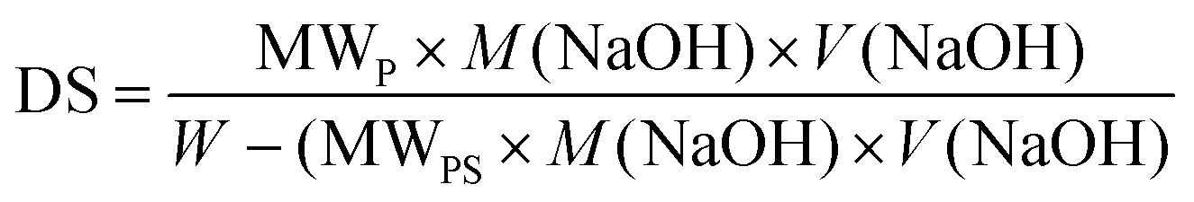
The sulfonation of PES was carried out using concentrated sulfuric acid. 5 g of PES was dissolved in 100 mL of concentrated sulfuric acid. The homogeneous solution was allowed to be continuously stirred for 48 h at room temperature and slowly poured into ice-cold water with continuous stirring. The resultant white fibrous polymer was washed with running water, followed by methanol to remove excess acid and trace impurities. The white fibrous polymer obtained was dried in a vacuum oven at 60 °C for 48 h and designated as SPES. The acid–base titration method was used to determine the degree of sulfonation (DS): a known weight (0.5 g) of the membrane was dissolved in 10 mL NMP solvent and titrated against 0.1 M NaOH using phenolphthalein as an indicator. DS was calculated by using eqn (1):24| | 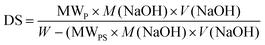 | (1) |
where MWP and MWPS are the molecular weight of repeating monomer in polymer and molecular weight of –SO3H group (81 g mol−1), respectively, W is the mass of sulfonated polymer, and M(NaOH) and V(NaOH) are molarity and volume of sodium hydroxide used to neutralize –SO3H group from the polymer.
2.4. Preparation SPES/E-PANI blend membrane
The solvent-casting approach was used to prepare dense polymeric membranes by blending SPES with E-PANI. EP1 stands for the mixture of 95 percent SPES and 5 percent E-PANI, EP2 for 90 percent SPES and 10 percent E-PANI, and EP3 for 85 percent SPES and 15 percent E-PANI.
SPES was prepared for comparison which was neat. The polymer was dissolved in a 10% (w/v) NMP solvent and subsequently cast onto a glass plate. The casting was followed by a drying process under an IR chamber, maintaining a temperature of 60 °C for 24 hours. Subsequently, the membrane was carefully peeled from the glass plate and subjected to a series of repeated acid–base conditioning procedures prior to its intended use. These conditioned membranes were stored in a saline solution.
2.5. Membrane characterization
Polymer formations were confirmed with 1H NMR spectra recorded with a Bruker DMX-300 NMR instrument at 500 Hz in DMSO-d6 solvent. A Zwick Roell BT-FR 2.5th 40 universal testing machine (UTM) was used to gauge the membranes’ tensile strength and elongation at break. The membranes’ TGA curves were recorded using a NETZSCH TG 209F1 Libra instrument at a scan rate of 5 °C min−1 between 30 °C and 600 °C. The membranes’ FT-IR spectra were captured using an Agilent Technologies 600 series. The spectra were captured in the 4000–400 cm−1 range. Using a JEOL JEM 7100F electron microscope from the USA along with energy-dispersive X-ray (EDX) spectroscopy at an accelerating voltage of 15–20 kV, membrane surface morphology was examined. The membranes’ topology and surface roughness were examined using an atomic force microscope (AFM) device (Ntegra Aura, NT-MDT, Moscow). The crystallographic structure of E-PANI was determined by powder XRD (Empyrean-Analytical).
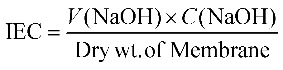
2.5.1. Ion exchange capacity (IEC).
To achieve complete protonation for IEC, a 2 × 2 cm piece of a membrane was submerged in 100 mL of 1 M HCl for 24 h. It was then poured into a NaCl solution with a defined volume and concentration. The membrane was repeatedly rinsed with distilled water before adding NaCl in order to wash away any extra acid that had clung to the surface. The exchanged protons were measured by titrating against 0.001 M NaOH after 24 h. IEC was determined utilising eqn (2):25| |  | (2) |
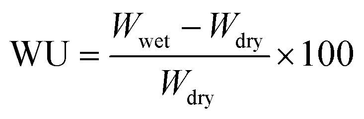
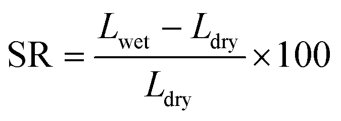
2.5.2. Swelling ratio and water uptake.
The change in weight and dimension of the wet and dry membranes, respectively, were used to compute the membrane water uptake (WU) and swelling ratio (SR). A membrane section that measured 10 cm long by 2 cm wide was submerged in deionized water for 24 h. To eliminate any surface water, a tissue was used to wipe the membrane. The membrane's length and wet weight were noted. Following a 24 h bake at 60 °C, its dry weight and length were determined. Eqn (3) and (4) were utilised to compute the WU and SR utilising wet and dry weights as well as changes in length values:26| |  | (3) |
| | 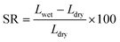 | (4) |
2.5.3. Proton conductivity.
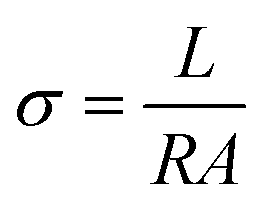
Using a CHI 700E potentiostat and a BT-112 conductivity cell from Scribner Associated, Inc., the impedance of the membranes was measured to determine their conductivity. The potentiostat was set with an amplitude of 5 mV and a frequency range of 1 Hz to 0.1 MHz. Eqn (5) was used to determine conductivity using the following information: L (cm), the distance between the electrodes; R, the observed impedance of the membrane; and A (cm2), the membrane's surface area.27| |  | (5) |
2.5.4. Permeability rate of vanadium ions.
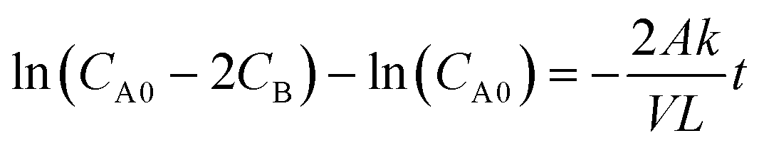
A two-compartment cell was used to determine the permeability rate of vanadium ions in various oxidation states. The experimental procedure was followed as reported in the literature.28 The increase in concentration of vanadium ions on the permeate side was determined by withdrawing samples at regular intervals for 24 h and analysing them using a UV-visible spectrophotometer. The amount of vanadium ions diffused through the membrane was calculated using eqn (6):| | 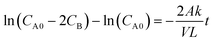 | (6) |
where CB is the concentration of the permeate side and CA0 is the starting concentration of vanadium solution (mol L−1). The term “permeability” refers to k/L (dm s−1). V stands for the compartment's volume (dm3), L for the membrane's thickness (dm), and t for the experiment's runtime (s). According to eqn (6), ln(CD0 − CE) vs. t should produce a straight line with a slope equal to −2Ak/VL, where A is the exposed area of the membrane (dm2). The slope of the line was used to calculate the permeability rate, k/L (dm s−1).
2.5.5. Chemical stability.
Before integrating the membrane into the VRFB test cell, it is crucial to evaluate its chemical and dimensional stability in order to ensure its extended cycle life. Following its immersion in a 2 M H2SO4 solution containing 1.6 M VO2+, its dimensions and mass change were monitored every 24 hours for analysis. It took 15 days to complete the investigation. The membrane's IEC, transport number, and conductivity were then evaluated to see how an acidic environment containing oxidative VO2+ ions would alter it.
2.6. Battery performance
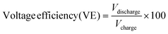
The polarisation curves for the membranes were captured using a constructed redox flow battery cell with an effective membrane area of 12 cm2 and an electrolyte solution of 1 M vanadium in 2 M H2SO4. The cell was discharged for a set amount of time at current densities ranging from 25 to 450 mA cm−2 after being fully charged at 50 mA cm−2 current density. A comparable constant voltage was measured. A commercial flow battery cell with a 25 cm2 effective cell area, supplied by Research Supporters India (RSI), was used to analyse the battery performance of blend membranes and Nafion 117. Using a battery tester (Batsol Neware), the cell was energised. The rate performance studies were conducted at different current densities, such as 20, 40, 60, 80, and 100 mA cm−2, without altering the solutions, which were 0.5 M vanadium(III) chloride dissolved in 50 mL of 2 M H2SO4 as negolyte and 0.5 M vanadium(IV) sulphate oxide hydrate dissolved in 50 mL of 2 M H2SO4 as posolyte. We assessed the membrane cycling stability by running the VRFB at 100 mA cm−2 for 100 charge/discharge cycles. By charging the battery to 1.6 V at a current density of 20 mA cm−2 and monitoring its self-discharge until the voltage neared 1.0 V, the open circuit potential (OCP) of the membrane was determined. The efficiencies of the battery were calculated as reported using eqn (7)–(9):29| | 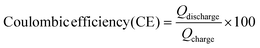 | (7) |
| |  | (8) |
| | | Energy efficiency (EE) = (CE × VE) × 100 | (9) |
3. Results and discussion
3.1. Polymer and membrane characterization
A processable E-PANI was synthesised and confirmed by FT-IR and NMR spectroscopy. The solubility of PANI was consistently reported to fall within the range of 2–5% in NMP solvent. However, our synthesized E-PANI polymer exhibits an impressive 8% solubility in NMP solvent. This enhanced solubility is likely attributed to the presence of 2-ethylaniline, which appears to prevent aggregation during the polymerization process, resulting in a PANI that is more amenable to processing. The FT-IR spectrum in Fig. S1a† shows the distinctive band at 3395 cm−1 attributed to the amino group's N–H stretching vibration.30 The absorption band at 1495 cm−1 relates to the C![[double bond, length as m-dash]](https://www.rsc.org/images/entities/char_e001.gif) C vibration of the aromatic ring, whereas the peak at 1590 cm−1 corresponds to the non-symmetric stretching of the benzoid ring.31,32 The band at 1307 cm−1 was caused by C–N stretching. E-PANI protonation is characterized by the existence of a strong band in the wavelength range33 from 1050 to 1100 cm−1. 1H-NMR spectrum shown in Fig. S1b† shows the –CH3 protons of the ethyl substituent at 3.0 ppm, while the –CH2 protons appeared at 3.5 and 3.8 ppm due to quinoide/benzonoid structure. As anticipated, quinoid protons were found at 6.8 and 8.2 ppm and aromatic protons between 7.5 and 8.0 ppm. Polymer's amorphous nature was demonstrated by a broad peak at a 2θ value of 27.7° in the recorded powder XRD pattern (Fig. S1c†).34,35 The functional groups interact with the solvent, effectively increasing the entropy of dissolution and thereby mitigating the interaction between the main polymer chains57–59 supported by the lesser aggregation of E-PANI seen in the SEM image in Fig. S1e† when compared to the unmodified PANI, shown in Fig. S1f.†
C vibration of the aromatic ring, whereas the peak at 1590 cm−1 corresponds to the non-symmetric stretching of the benzoid ring.31,32 The band at 1307 cm−1 was caused by C–N stretching. E-PANI protonation is characterized by the existence of a strong band in the wavelength range33 from 1050 to 1100 cm−1. 1H-NMR spectrum shown in Fig. S1b† shows the –CH3 protons of the ethyl substituent at 3.0 ppm, while the –CH2 protons appeared at 3.5 and 3.8 ppm due to quinoide/benzonoid structure. As anticipated, quinoid protons were found at 6.8 and 8.2 ppm and aromatic protons between 7.5 and 8.0 ppm. Polymer's amorphous nature was demonstrated by a broad peak at a 2θ value of 27.7° in the recorded powder XRD pattern (Fig. S1c†).34,35 The functional groups interact with the solvent, effectively increasing the entropy of dissolution and thereby mitigating the interaction between the main polymer chains57–59 supported by the lesser aggregation of E-PANI seen in the SEM image in Fig. S1e† when compared to the unmodified PANI, shown in Fig. S1f.†
SPES was prepared by using concentrated H2SO4. The sulfonation was confirmed by 1H-NMR (Fig. S3†). From the spectra, it can be seen that peaks in the range 7.0–7.3 ppm correspond to the c, d, e, and g protons present in the aromatic ring (labelled structure: inset Fig. S3†). The peaks for the aromatic protons a, b, and f of the sulfonated benzene ring were observed in the range 7.7–7.9 ppm. If an acidic proton did not appear, it may be due to hydrogen bonding with a neighbouring oxygen atom. The degree of sulfonation (DS) for SPES calculated using eqn (1) was found to be 44.7%.
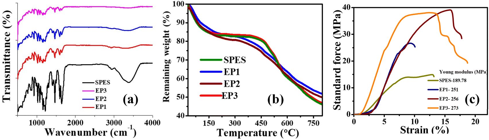
The membranes were prepared by simple physical blending in NMP solvent as shown in Fig. 1a, followed by membrane casting. The presence of E-PANI in SPES and their weak ionic interactions (Fig. 1b) were supported by recorded FT-ATR spectra (Fig. 2a). Dry membrane samples were used for FT-ATR analysis. For composite membranes EP1, EP2, and EP3, the peaks at 1505 and 1590 cm−1 are due to non-symmetric ring stretching of benzoid and quinoid rings.36 The 1300 cm−1 peak was attributed to C–N stretching of secondary aromatic amine.37 In-plane and out-of-plane C–H bending resulted in sharp peaks at 1150–1200 and 800–950 cm−1, respectively.38 The peaks at 1148 and 1577 cm−1 were due to the stretching of the C–C and C–C aromatic rings.39 All the membrane OSO symmetric stretching and sulfonic acid OS stretching caused the existence of strong bands in the wavelength range from 950 to 1100 cm−1.40 At 3400 cm−1 for the SPES membrane, a strong and broad band for the –OH group of sulfonic acid was clearly observed.41 However, the intensity of this band decreased as E-PANI loading increased, indicating possible acid–base interactions between the sulfonic group of SPES and the amine group of E-PANI.
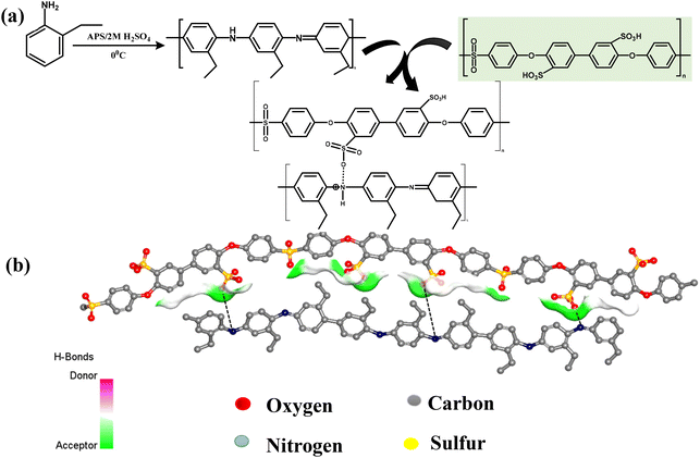 |
| | Fig. 1 (a) Polymerization of 2-ethylaniline (E-PANI) and blending with SPES. (b) Illustration of 3D image of ionic interaction between E-PANI and SPES. | |
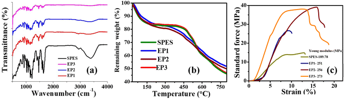 |
| | Fig. 2 Spectroscopic analysis of SPES/E-PANI blend membranes. (a) FT-IR; (b) TGA; and (c) stress vs. strain plot. | |
The thermal stability of the membranes was studied using TGA. The recorded TGA curves of the synthesised membranes are represented in Fig. 2b. The SPES and E-PANI blend membranes showed three-step thermal degradation, as expected, according to Fig. 2b. The first degradation at 150 °C is related to the bound water in the membrane. The observed weight loss was around 15.83, 14.98, 14.34, and 13.06% for SPES, EP1, EP2, and EP3, respectively. The decomposition of the –SO3H groups is responsible for the second weight loss between 150 and 450 °C, which was found to be 31.39, 29.81, 28.74, and 27.04% for SPES, EP1, EP2, and EP3 membranes, respectively. Thermal degradation beyond 450 °C is because of degradation of the polymeric backbone. From the observed TGA curves, it is clear that, as the concentration of E-PANI increases in SPES, the thermal stability of the membrane also increases. This was explained based on the inherent thermostability of E-PANI42 and the acid–base interactions between the sulfonic acid group of SPES and the amine/imine group of E-PANI. The blending of E-PANI led not only to better thermal stability but also to superior mechanical properties (Fig. 2c). The plot of stress versus strain clearly shows the substantial increase in the Young's modulus of the membrane with an increase in E-PANI content. The calculated Young's modulus for SPES, EP1, EP2, and EP3 membranes was 189, 251, 256, and 273 MPa, respectively. Malmonge et al. showed that blends with 12 and 22.4 wt% of PANI increased the Young's modulus of PANI from 1.2 GPa for PVDF to 1.5 GPa. Additionally, Sridhar and colleagues reported that the mechanical strength of neat SPES increased after blending with PANI due to an ionic interaction between the two dissimilar polymers, one of which is basic in nature and the other acidic.43 The rise in Young's modulus is caused by an ionic contact between the two polymers.
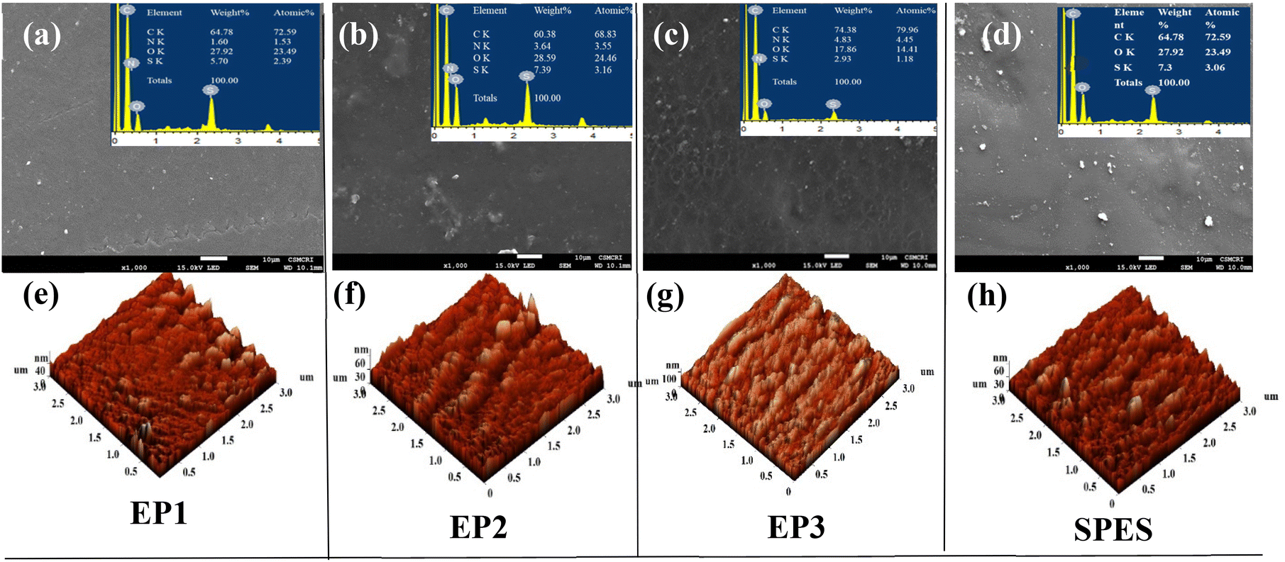
The synthesized blend membranes were found to be visibly transparent. Due to the presence of E-PANI, they had a blue hue, and when E-PANI was loaded, the hue became more intense. The membranes were free of cracks, as seen in the SEM images (Fig. 3a–d). The elemental analyses in the insets of Fig. 3a–d show that the sulfonic group of SPES contains sulphur, while E-PANI contains nitrogen. A low degree of phase separation was visible through SEM images, particularly for EP3 membranes (membranes with the highest loading of E-PANI). The reason for phase separation can be explained based on two possibilities: (a) polysalt formation due to ionic interaction of the sulfonic acid of SPES with the amine group of E-PANI, and (b) differences in the solubility of E-PANI and SPES in the casting solvent, resulting in different evaporation rates of the membrane casting solvent. The polysalt formation and the presence of characteristic epitaxial polymer chains in E-PANI can certainly contribute to the roughness of the membrane (Table 1).43 In Fig. 3e–h are shown 3D images of the surface topography of the synthesised membranes using AFM. As expected, the surface roughness of the composite membranes increased with E-PANI loading. The peak-to-peak distance and average roughness for the neat SPES membrane were found to be 67.37 and 5.88 nm, respectively. The peak-to-peak distance for EP1, EP2, and EP3 was found to be 74.98, 79.36, and 127 nm, respectively, while the surface roughness was found to be 32.28, 35.88, and 72.06 nm for EP1, EP2, and EP3, respectively.
 |
| | Fig. 3 Representation of surface morphology of SPES/E-PANI membranes. (a–d) SEM images with insets showing EDX analysis; (e–h) 3D images of atomic force microscopy of EP1, EP2, EP3, and SPES, respectively. | |
Table 1 Surface roughness parameters of the E-PANI blend membranes and SPES obtained from AFM images
| Membranes |
SPES |
EP1 |
EP2 |
EP3 |
| Peak to peak (nm) |
67.36 |
74.98 |
79.38 |
127.00 |
| Mean value (nm) |
27.77 |
32.28 |
35.88 |
72.06 |
| Roughness average (Sa) (nm) |
5.88 |
5.99 |
5.69 |
11.54 |
| Root mean square (Sq) (nm) |
7.55 |
7.67 |
7.81 |
14.71 |
Ionic transference measurement.
Since PANI is an intrinsically electronic conductive material, its suitability for redox flow batteries must be confirmed by measuring the contribution of ionic and electronic transfer.44 The current-time plots for the E-PANI-blended SPES membranes are shown in Fig. 4. The values of ionic transference number ti and electron transference number te were determined using the following equations:| |  | (10) |
| |  | (11) |
where I0 is a total initial current at the time t = 0 (ionic and electronic) and It is the current at saturation (electronic current only), determined from current versus time plot.45
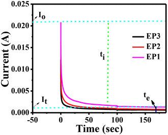 |
| | Fig. 4 Current vs. time plot for E-PANI/SPES blend membranes. | |
The ionic species in the membranes depleted with time, diminishing the initial total current and then attaining a constant state in a fully depleted state (ti). Until steady state is reached, ionic migration continues. When the cell is in its steady state, it is polarised, and any remaining current flow is caused by electron migration across surfaces. E-PANI present in the membrane causes this behaviour. For the EP1, EP2, and EP3 membranes, respectively, the current owing to the electron transfer was found to be 3.5%, 3.70%, and 4.06%, and the current due to the ionic transfer contribution was found to be 96.8%, 96.29%, and 95.4%. As a result, ionic transfer makes a far larger contribution than electronic transfer, this being one of the major reasons we chose to investigate membranes of E-PANI mixed with SPES in redox flow batteries.
By evaluating swelling ratio, water content, IEC, and impedance under the same experimental settings as for Nafion 117, the membranes’ physicochemical and electrochemical properties were assessed (Table 2). The calculated proton conductivity of the membranes was found to be 28.3, 28.9, 27.8, and 25.7 mS cm−1 for SPES, EP1, EP2, and EP3, respectively. The conductivity of E-PANI blend membranes is due to the formation of short-range, very fine, characteristic fibrillar structures that connect the discretely dispersed E-PANI, forming continuous conducting channels,46 as well as the precise sulfonation of PES, which ensured a high concentration of exchangeable ions in the polymer matrix.47 The decrease in conductivity values supports the hypothesis of a densified polymer matrix given by acid–base interactions between the two polymers. This is achieved by partially sacrificing the sulfonic groups and, therefore, slightly lowering the proton conductivity and proton-exchange capacity.22 The IEC values for SPES, EP1, EP2, and EP3 were found to be 1.42, 1.32, 1.25, and 1.22 meq g−1, respectively. The decreasing trend for IEC with the increase in E-PANI content can be explained on the basis of the interaction of E-PANI with the sulfonic group of SPES. Certainly, acid–base interaction in the blend membranes is dependent on the concentration of E-PANI loading; with an increase in E-PANI concentration, the availability of sulfonic groups for ion exchange decreases, thereby decreasing the IEC of the membranes.18,19,21,23 In the case of counter ion exchange facilitated by EPANI and SPES, a thermodynamically favourable process hinges on the condition of a negative Gibbs free energy change (ΔG), necessitating the concurrent negativity of both enthalpy (ΔH) and entropy (ΔS) (ΔG = ΔH − TΔS). This implies that the system typically relies on specific interactions between the two components. These interactions span a spectrum, ranging from strong ionic interactions to nonbonding interactions, including weak bonding such as hydrogen bonding, ion-dipole, dipole–dipole, and donor–acceptor interactions. A comprehensive study of these interaction types in the literature shows the miscibility of polymer blends.48–51 The membranes’ water uptake and swelling ratio values correspond to their IEC values. The calculated water uptake values for SPES, EP1, EP2, and EP3 membranes were 30.4, 17.1, 16.6, and 19.8%, respectively, while the swelling ratio values were 15.1, 13.3, 12.6, and 11.8%. Low swelling ratios for the blend membranes should result in low electrolyte uptake during battery operation and hence low diffusion of vanadium ions. Diffusion of vanadium ions in various oxidation states across the membranes measured with a two-compartment cell is presented in Table 3. Amongst the prepared blend membranes, EP3 showcased the lowest permeability rate values of 0.43 × 10⁻⁸, 0.86 × 10⁻⁷, and 1.89 × 10⁻⁸ dm s−1 for VO2+, VO2+, and V3+ ions, respectively. For EP2, the permeability rates of VO2+, VO2+, and V3+ ions were 1.04 × 10⁻⁸, 2.04 × 10⁻⁷, and 3.13 × 10⁻⁸ dm s−1, respectively, whereas for EP1, the permeability rates of VO2+, VO2+, and V3+ ions were 1.02 × 10⁻⁸, 3.16 × 10⁻⁷, and 4.56 × 10⁻⁸ dm s−1, respectively. The diffusion coefficient and permeability rate values for E-PANI blends and neat SPES are presented in Table 3.
Table 2 Comparison of physiochemical and electrochemical properties of the E-PANI blend membranes with those of Nafion 117 and SPES
| Membrane code |
IEC (meq g−1) |
Water content (%) |
Swelling ratio (%) |
Conductivity (mS cm−1) |
Young's modulus (MPa) |
Thickness (μm) |
| SPES |
1.42 ± 0.04 |
30.4 ± 0.7 |
15.1 ± 0.6 |
28.3 ± 1.0 |
189 ± 5.42 |
110 |
| EP1 |
1.32 ± 0.03 |
17.1 ± 0.5 |
13.3 ± 0.5 |
28.9 ± 2.3 |
251 ± 4.31 |
112 |
| EP2 |
1.25 ± 0.01 |
16.6 ± 0.2 |
12.6 ± 0.1 |
27.8 ± 1.8 |
256 ± 4.67 |
128 |
| EP3 |
1.22 ± 0.01 |
19.8 ± 0.5 |
11.8 ± 0.5 |
25.7 ± 2.1 |
273 ± 4.52 |
140 |
| Nafion117 |
0.97 ± 0.06 |
20.4 ± 0.2 |
11.0 ± 0.1 |
56.4 ± 2.6 |
258 ± 2 |
168 |
Table 3 Vanadium ion permeability rate and diffusion coefficient of SPES/E-PANI blend membranes determined using a two-compartment diffusion cell
| Membrane code |
V3+ |
V4+ |
V5+ |
|
K (dm2 s−1) |
Permeability (dm s−1) |
K (dm2 s−1) |
Permeability (dm s−1) |
K (dm2 s−1) |
Permeability (dm s−1) |
| SPES |
2.09 × 10⁻⁹ |
1.83 × 10⁻⁷ |
3.47 × 10⁻⁹ |
3.27 × 10⁻⁷ |
1.23 × 10⁻⁹ |
1.16 × 10⁻⁷ |
| EP1 |
6.1 × 10⁻¹⁰ |
4.56 × 10⁻⁸ |
3.36 × 10⁻⁹ |
3.16 × 10⁻⁷ |
1.08 × 10⁻¹⁰ |
1.02 × 10⁻⁸ |
| EP2 |
4.11 × 10⁻¹⁰ |
3.13 × 10⁻⁸ |
2.68 × 10⁻⁹ |
2.04 × 10⁻⁷ |
1.12 × 10⁻¹⁰ |
1.04 × 10⁻⁸ |
| EP3 |
2.45 × 10⁻¹⁰ |
1.89 × 10⁻⁸ |
1.11 × 10⁻⁹ |
0.86 × 10⁻⁷ |
5.58 × 10⁻¹⁰ |
0.43 × 10⁻⁸ |
| Nafion 117 |
2.9 × 10⁻⁹ |
3.40 × 10⁻⁷ |
4.5 × 10⁻⁹ |
5.37 × 10⁻⁷ |
2.2 × 10⁻⁹ |
2.68 × 10⁻⁷ |
A high concentration of sulphuric acid from both sides will be in constant contact with the membrane of a VRFB cell during battery operation, as will a highly oxidising environment of VO2+ ions from the catholyte. Therefore, it is very important to evaluate the chemical stability of the membranes in a highly oxidative environment. Fig. S3† shows the dimension and weight change of E-PANI blend membranes with respect to the number of days. The weight and dimension fluctuate rapidly in the early stages of the experiment. The values, however, held steady as the study drew to a conclusion. The average dimension change for EP1, EP2, and EP3 membranes was 24, 20, and 18%, respectively. The least dimension change for EP3 membrane is due to the high composition of E-PANI, which effectively interacts with the sulfonic group of SPES, resulting in ionic crosslinking, and hence suppressing the swelling ratio of the membrane. The average weight gain was found to be 17, 17.5, and 11.8% for EP1, EP2, and EP3 membranes. Electrochemical characteristics were recorded to mark the completion of the experiment. The obtained data were compared to the data from the membranes prior to chemical treatment (Table 4). The irreversible sorption of vanadium ions onto the membrane matrix was believed to be the cause of the observed rise in water content. However, this sorption of vanadium ions decreased the IEC and conductivity of the membranes.
Table 4 Comparison of electrochemical properties for E-PANI blend membranes and SPES before and after chemical stability study
| Membrane code |
Water content (%) |
IEC (meq g−1) |
Conductivity (mS cm−1) |
| Before |
After |
Before |
After |
Before |
After |
| SPES |
30.4 |
43.1 |
1.42 |
0.78 |
28.3 |
18.9 |
| EP1 |
17.1 |
36.4 |
1.32 |
0.89 |
28.9 |
21.4 |
| EP2 |
16.6 |
38.9 |
1.25 |
0.73 |
27.8 |
25.4 |
| EP3 |
19.8 |
33.3 |
1.22 |
0.80 |
25.7 |
25.1 |
| Nafion 117 |
20.4 |
20.1 |
0.97 |
0.91 |
56.4 |
55.8 |
3.2. Vanadium redox flow battery performance
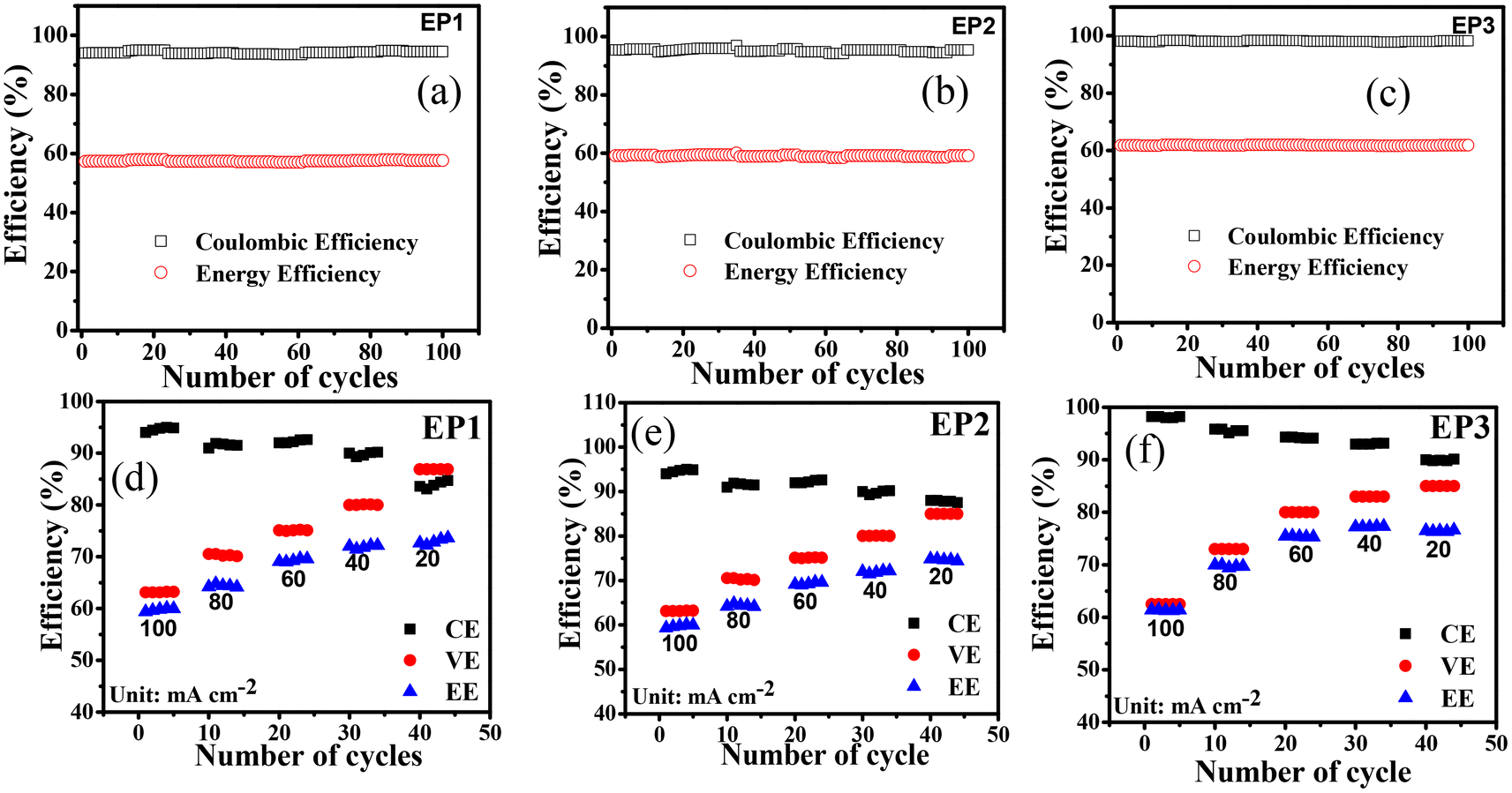
Fig. 5a–c shows results for 100 charge/discharge cycles operated at a current density of 100 mA cm−2 for VRFBs assembled with EP1, EP2, and EP3 membranes. The symmetric single-cell performance of the EP3 membrane was able to achieve 98.0, 63.0, and 62.0% for CE, VE, and EE, respectively. The CE, VE, and EE of the EP2 and EP1 membranes were 95.0, 62.0, 58.9% and 94.0, 61.0, 57.9%, respectively. The results were in accord with the proton conductivity and vanadium ion permeability rate. However, a lower EE for each membrane raises the possibility that the system has internal resistance. The operating conditions of the battery's high current density, which can raise the system's ohmic resistance,52 led to a relatively low EE for all E-PANI composites.
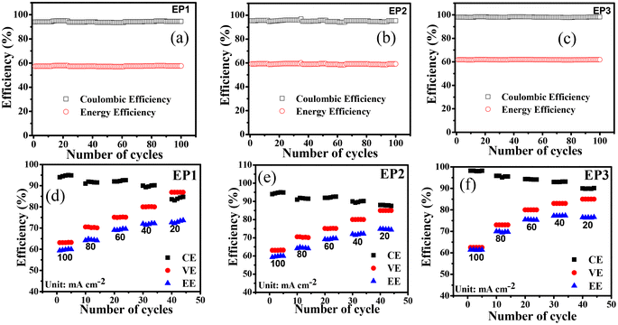 |
| | Fig. 5 Battery performance of E-PANI composite membranes. (a–c) 100 cycles at 100 mA cm−2 of EP1, EP2, and EP3, respectively. (d–f) Rate performance with number of cycles at different current density of EP1, EP2, and EP3, respectively. | |
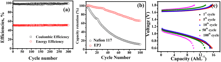
Fig. 5d–f shows CE, VE, and EE for cells operated at different current density to study the rate capability of the composite membranes. Characteristically, CE increased while VE and EE decreased as the current density increased from 20 to 100 mA cm−2 for all the membranes. As current density resulting less time was required for the cell to charge and discharge,53 resulting less vanadium ion crossover and hence high coulombic efficiency. In contrast, VE decreased with increasing current density due to the increasing internal resistance in the system and ohmic polarization.54–56 Amongst prepared membranes, EP3 membrane had the best electrochemical properties along with lowest diffusion coefficient for different vanadium ions and this was reflected in its VRFB performance as it showed highest CE (90.5, 92.0, 94.3, 95.5, and 98.0%), VE (85.0, 83.0, 80.0, 73.0, and 63.0%), and EE (77.0, 76.0, 75.0, 70.0, and 62.0%) at 20, 40, 60, 80, and 100 mA cm−2, respectively. In identical experimental conditions, VRFB cell assembled with EP1 displayed CE of 85.0, 90.0, 92.0, 91.5, and 94%, VE of 83.0, 80.0, 75.1, 70.6, and 61.0%, and EE of 72.0, 71.5, 69.0, 64.0, and 57.9% at 20, 40, 60, 80, and 100 mA cm−2. For EP2, the calculated CE of 88.0, 91.0, 92.0, 93.0, and 95.0%, VE of 84.0, 80.1, 75.2, 70.5, and 62.0%, and EE of 74.0, 72.5, 69.5, 64.4, and 59.0% was recorded at 20, 40, 60, 80, and 100 mA cm−2, respectively. The Nafion 117 membrane showed 95% coulombic efficiency, voltage efficiency of 60.1, and 57.0% energy efficiency at 100 mA cm−2 current density (Fig. S5†). The cycling stability of the best membrane EP3 was further evaluated in an asymmetrical cell and data are presented in Fig. 6 along with those for Nafion 117 for comparison in identical experimental conditions. In 300 charge/discharge cycles at 140 mA cm−2, it delivered 99.5, 53.0, and 52.7% for CE, VE, and EE, respectively (Fig. 6a). In terms of capacity decay, it was observed that the EP3 membrane outperformed Nafion 117. It showed only a 35% capacity decay corresponding to 0.35% decay per cycle whereas Nafion 117 showed an 85% capacity decay (Fig. 6b). Fig. 6c shows the overlap of α graph of 1st, 5th, 10th, 50th, and 100th cycles of the charge/discharge cycles. The capacity retention clearly indicates the Donnan exclusion of vanadium ions by the weakly positively charged E-PANI backbone has a substantial effect on capacity retention.
 |
| | Fig. 6 Battery performance of E-PANI composite EP3 membranes. (a) Charge–discharge during 300 cycles at 140 mA cm−2. (b) Capacity retention with cycle number at 140 mA cm−2. (c) Capacity at different cycle numbers at 140 mA cm−2. | |
The rate performance and cycling test for E-PANI composite membranes were compared to those for PANI composite membranes reported in the literature (Table S1†) and with other membranes (Table S2†). Wessling and his team developed the SPEEK/PANI blend membrane, and they observed that when operated at 50 mA cm−2, the low ion diffusivity in VRFB results in high CE of 99%, VE of 92%, and EE of 90%. However, they only demonstrated cycling stability up to 30 cycles. The leaching of non-homogeneous PANI could render this possible. The SPEEK/PANi-GO composite membrane designed by Shi et al. demonstrated 300-cycle stability with CE of 98.5%, VE of 83%, and EE of 81.7%, nevertheless operating at a low current density of 30 mA cm−2. Overall, the maximum current density achieved for rate performance and cycling stability in the literature for PANI membranes was in the range of 60–40 mA cm−2, while the prepared E-PANI-blend SPES membranes delivered good VRFB performance at a higher current density of 140 mA cm−2 up to 300 cycles, exhibiting their potential for consistent performance at higher operating current densities with a long service lifetime in VRFBs.
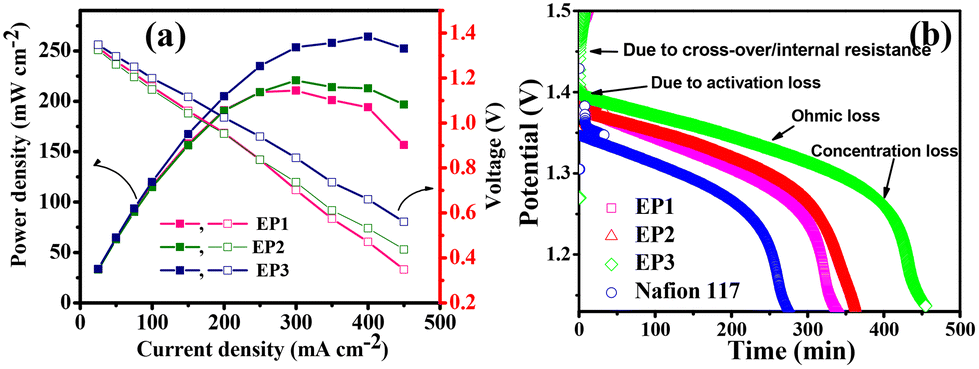
Fig. 7a shows a plot of voltage and power density versus current density. The VRFB cell with EP1, EP2, and EP3 reached peak power densities of 192, 212, and 266 mW cm−2 at 400 mA cm−2 current density, which was found to be higher than that with Nafion 117 in an identical experimental condition. High power densities for the blend membranes can be explained based on the synergistic effect of a well-defined conducting path anchored by characteristic fibrillar structures interconnecting with the homogeneously dispersed PANI molecules. After the polarisation experiment, the battery's self-discharge was monitored after being charged at 1.6 volts at 20 mA cm−2 until the voltage achieved 1.0 volts. Fig. 7b shows the OCV for membranes; in the same experimental setup, Nafion 117 was faster at self-discharging than VRFB cells employing composite E-PANI membranes. The time needed for the EP1, EP2, and EP3 membranes to self-discharge was inversely related to the rates of vanadium-ion permeability. The self-discharge times for EP1, EP2, and EP3 were 5.6, 6.1, and 7.5 h, respectively, whereas the self-discharge time for Nafion 117 was 4 h.
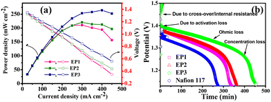 |
| | Fig. 7 Battery performance of SPES/E-PANI blend membranes. (a) Polarization curve and (b) open circuit potential of SPES/E-PANI blend membranes and Nafion 117. | |
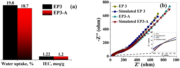
To make sure there had been no negative alterations to the electrochemical and physicochemical characteristics of the membranes after battery performance, EP3-A was analyzed. Ionic conductivity, IEC, and water uptake all exhibited a slight decrease for the EP3-A membrane. This was explained in light of the irreversible sorption of vanadium ions during battery examination. IEC and water uptake were both observed to be at 1.2 meq g−1 and 18.7%, respectively (Fig. 8a). The calculated conductivities from the impedance spectra (Fig. 8b) for EP3 and EP3-A were found to be 25.7 and 23.8 mS cm−1, respectively, and there was no change found in surface morphology (Fig. S5†). After an intensive battery study, the acceptable variation in electrochemical properties (Table S3†) for the best-performing EP3 membrane shows its long-term operational stability and best utility in VRFB applications.
 |
| | Fig. 8 Post-battery analysis of EP3-A membrane and comparison with pre-battery analysis of EP3. (a) IEC and water uptake of EP3 and EP3-A membranes. (b) Impedance spectra of EP3 and EP3-A membranes. | |
4. Conclusions
To conclude, we successfully synthesized processable E-PANI, which was confirmed by 1H-NMR, FT-IR, and powder XRD. Three blend membranes, i.e., EP1, EP2, and EP3, were prepared by the solvent-casting method with different weight ratios of SPES and E-PANI. The observed IEC, WU, and SR decreased with an increase in E-PANI loading due to the ionic interaction between the sulfonic acid group of SPES and the amine/imine functionality of E-PANI. The membrane with the highest loading of E-PANI, i.e., 15 wt% (EP3), had the highest ionic conductivity and acceptable chemical stability in a 1.6 M VO2+ solution and comparatively low diffusion coefficient for vanadium ions. VRFB assembled with EP3 displayed the highest values of 99.5, 53.0, and 52.7% for CE, VE, and EE, respectively, throughout 300 charge/discharge cycles at 140 mA cm−2 current density. The polarization curve experiments revealed peak power densities of 192, 212, and 266 mW cm−2 at a limiting current density of 400 mA cm−2 for EP1, EP2, and EP3, respectively. The self-discharge times of EP1, EP2, and EP3 were longer than that of Nafion 117. Retention of acceptable electrochemical and physicochemical properties after VRFB operation indicates the membranes as potential candidates as separators for VRFB applications.
Conflicts of interest
There are no evident conflicts.
Acknowledgements
RKN thanks the Council of Scientific and Industrial Research, India, and Technology mission division energy and water for their financial support, grant number DST/TMD/MES/2K18/194(G), (MLP-0063). It is stated that Director CSIR-CSMCRI provides ongoing assistance and motivation. The Analytical Discipline & Centralized Instrument Facility, CSIR-CSMCRI, Bhavnagar, supplied instrumentation facilities for which RKN is also appreciative. CSIR-CSMCRI manuscript number 236/2022.
References
- A. G. MacDiarmid, Angew. Chem., Int. Ed., 2001, 40, 2581–2590, DOI:10.1002/1521-3773(20010716)40.
- S. Tan, A. Laforgue and D. Bélanger, Langmuir, 2003, 19, 744–751, DOI:10.1021/la0263054.
- M. Beygisangchin, S. A. Rashid, S. Shafie, A. R. Sadrolhosseini and H. N. Lim, Polymers, 2021, 13, 2003, DOI:10.3390/polym13122003.
- M. A. Khan and M. R. Arsalan, J. Membr. Sci. Technol., 2016, 62, 2, DOI:10.4172/2155-9589.100015.
- K. Zhang, X. Gu, Q. Dai, B. Yuan, Y. Yan and M. Guo, Vacuum, 2020, 170, 108990, DOI:10.1016/j.vacuum.2019.108990.
- A. Chaoudhary, Sens. Actuators, B, 2009, 13, 8318–8325, DOI:10.1016/j.snb.2009.01.019.
- P. Humpolicek, V. Kasparkova, P. Saha and J. Steijskal, Synth. Met., 2012, 162, 722–727, DOI:10.1016/j.synthmet.2012.02.024.
- G. R. Guillen, T. P. Farrell, R. B. Kaner and E. M. V. Hoek, J. Mater. Chem., 2010, 20, 4621–4628, 10.1039/b925269j.
- V. Babel and L. B. Hiran, Polym. Compos., 2021, 1, 16, DOI:10.1002/pc.26048.
- M. R. Anderson, B. R. Mattes, H. Reiss and R. B. Kaner, Synth. Met., 1991, 41–43, 1151–1154, DOI:10.1016/0379-6779(91)91575-U.
- Y. Wang, L. Li, X. Zhang, J. Li, C. Liu, N. Li and Z. Xie, J. Membr. Sci., 2019, 58, 9117246, DOI:10.1016/j.memsci.2019.117246.
- A. Sarihan, Mater. Today Commun., 2020, 24, 101104, DOI:10.1016/j.mtcomm.2020.101104.
- D. D. Fazullina, G. V. Mavrin and I. G. Shaikhiev, Pet. Chem., 2017, 57, 165–171, DOI:10.1134/S0965544116110062.
- T. Sata, Y. Ishii, K. Kawamura and K. Matsusaki, J. Electrochem. Soc., 1999, 146, 585, DOI:10.1149/1.1391648.
- S. Tan, V. Viau, D. Cugnod and D. Bélanger, Electrochem. Solid-State Lett., 2002, 5, 55–58, DOI:10.1149/1.1508552.
- P. K. Prajapati, R. Nimiwal, P. S. Singh and R. K. Nagarale, Polymer, 2019, 170, 168–178, DOI:10.1016/j.polymer.2019.03.016.
- P. K. Prajapati, N. N. Reddy, R. Reddy, P. S. Singh, S. Adimurthy and R. K. Nagarale, Sep. Purif. Technol., 2020, 233, 115989, DOI:10.1016/j.seppur.2019.115989.
- R. K. Nagarale, G. S. Gohil, V. K. Shahi, G. S. Trivedi and R. Rangarajan, J. Colloid Interface Sci., 2004, 277, 162–171, DOI:10.1016/j.jcis.2004.04.027.
- S. J. Yuan, Z. Wang, Z. H. Qiao, M. M. Wang, J. X. Wang and S. C. Wang, J. Membr. Sci., 2011, 378, 425–424 CrossRef CAS.
- R. K. Nagarale, G. S. Gohil and V. K. Shahi, J. Membr. Sci., 2006, 28, 0389–0396, DOI:10.1016/j.memsci.2006.01.043.
- B. Schwenzer, S. Kim, M. Vijayakumar, Z. Yang and J. Liu, J. Membr. Sci., 2011, 372, 11–19, DOI:10.1016/j.memsci.2011.01.025.
- O. David, K. Percin, T. Luo, Y. Gendel and M. Wessling, J. Energy Storage, 2015, 1, 65–71, DOI:10.1016/j.est.2015.01.001.
- Y. Zhang, H. Wang, W. Yu and H. Shi, ChemistrySelect, 2018, 3, 9249–9258, DOI:10.1002/slct.201801548.
- D. Palamara, P. Bruzzaniti, L. Calabrese and E. Proverbio, Prog. Org. Coat., 2021, 154, 106193, DOI:10.1016/j.porgcoat.2021.106193.
- R. K. Nagarale, G. S. Gohil and V. K. Shahi, Adv. Colloid Interface Sci., 2006, 119, 97–130, DOI:10.1016/j.cis.2005.09.005.
- M. Y. Kariduraganavar, R. K. Nagarale, A. A. Kittur and S. S. Kulkarni, Desalination, 2006, 197, 225–246, DOI:10.1016/j.desal.2006.01.019.
- S. Sreenath, N. K. Sharma and R. K. Nagarale, RSC Adv., 2020, 10, 44824, 10.1039/d0ra08316j.
- L. Cao, A. Kronander, A. Tang, D. Wang and S. M. Kazacos, Energies, 2016, 9(1058), 1–15, DOI:10.3390/en9121058.
- S. Sreenath, P. S. Nayanthara, C. M. Pawar, M. C. Noufal and R. K. Nagarale, J. Energy Storage, 2021, 40, 102689, DOI:10.1016/j.est.2021.102689.
- S. Senthilkumar and A. Rajendran, MOJ Poly. Sci., 2017, 1(6), 00031, DOI:10.15406/mojps.2017.01.00031.
- M. V. Kulkarni, A. K. Viswanath, R. Marimuthu and R. Milind, J. Polym. Sci. A Polym. Chem., 2004, 42, 2043–2049, DOI:10.1002/pola.11030.
-
U. M. Chougale, J. V. Thombare and V. J. Fulari, Synthesis of Polyaniline nanofibres by SILAR method for Supercapacitor application. International Conference on Energy Efficient Technologies for Sustainability, 2013. DOI:10.1109/ICEETS.2013.6533537.
- R. M. Sandra, D. Huerta-Vilca and A. J. Motheo, Eur. Polym. J., 2004, 40, 2033–2041, DOI:10.1016/j.eurpolymj.2004.05.016.
- S. Saravanana, C. J. Mathai, M. R. Anantharaman, S. Venkatachalam and P. V. Prabhakaran, J. Phys. Chem. Solids, 2006, 67, 1496–1501, DOI:10.1016/j.jpcs.2006.01.100.
- Z. Tian, H. Yu, L. Wang, M. Saleem, F. Ren, P. Ren, Y. Chen, R. Sun, Y. Sun and L. Huang, RSC Adv., 2014, 4, 28195, 10.1039/c4ra03146f.
- A. John, S. Palaniappan, D. Djurado and A. Pron, J. Polym. Sci., Part A: Polym. Chem., 2007, 46, 1051–1057, DOI:10.1002/pola.22448Ftir.
- E. T. Kang, K. G. Neoh and K. L. Tan, Prog. Polym. Sci., 1998, 23, 211–324, DOI:10.1016/S0079-6700(97)00030-0.
- J. Tang, X. Jing, B. Wang and F. Wang, Synth. Met., 1988, 24, 231–238, DOI:10.1016/0379-6779(88)90261-5.
- B. S. Singu, P. Srinivasan and S. Pabba, J. Electrochem. Soc., 2012, 159, A6–A13, DOI:10.1149/2.036201jes.
- C. Klaysoma, B. P. Ladewiga, G. Q. M. Lua and L. Wang, J. Membr. Sci., 2011, 368, 48–53, DOI:10.1016/j.memsci.2010.11.006.
- W. Zhao, Q. Mou, X. Zhang, J. Shi, S. Sun and C. Zhao, Eur. Polym. J., 2013, 49, 738–751, DOI:10.1016/j.eurpolymj.2012.11.018.
- S. Tan and D. Bélanger, J. Phys. Chem. B, 2005, 109, 23480–23490, DOI:10.1021/jp054724e.
- H. Nagar, N. Sahu, V. V. B. Rao and S. Sridhar, Renewable Energy, 2020, 146, 1262e1277 CrossRef.
- S. Shkirskaya, M. Kolechko and N. Kononenko, Curr. Appl. Phys., 2015, 15, 1587–1592, DOI:10.1016/j.cap.2015.09.017.
- N. M. Kocherginsky and Z. Wang, Synth. Met., 2006, 156, 1065–1072, DOI:10.1016/j.synthmet.2006.06.021.
- M. S. A. Rani, N. H. Hassan, A. Ahmad, H. Kaddami and N. S. Mohamed, Ionics, 2016, 22, 1855–1864, DOI:10.1007/s11581-016-1728-8.
- Y. Cao, P. Smith and A. J. Heeger, Synth. Met., 1992, 48, 91–97, DOI:10.1016/0379-6779(92)90053-L.
- D. Rana, K. Bag, S. N. Bhattacharya and B. M. Mandal, J. Polym. Sci., Polym. Phys. Ed., 2000, 38, 369–375 CrossRef CAS.
- D. Rana, B. M. Mandal and S. N. Bhattacharyya, Macromolecules, 1996, 29, 1579–1583 CrossRef CAS.
- D. Rana, B. M. Mandal and S. N. Bhattacharyya, Polymer, 1996, 37, 2439–2443 CrossRef CAS.
- D. J. Blundell and V. Bayon, Polymer, 1993, 34, 1454–1459 CrossRef.
- N. Dianat, M. S. Rahmanifar, A. Noori, M. F. El-Kady, X. Chang, R. B. Kaner and M. F. Mousavi, Nano Lett., 2021, 21, 9485–9493, DOI:10.1021/acs.nanolett.1c02843.
- P. P. Bavdane, S. Sreenath, D. Y. Nikumbe, C. M. Pawar, C. K. Kuzhiyil and R. K. Nagarale, ACS Appl. Energy Mater., 2022, 5, 13189–13199, DOI:10.1021/acsaem.2c01080.
- S. Sreenath, P. S. Nayanthara, C. M. Pawar, D. Y. Nikumbe, B. Bhatt and R. K. Nagarale, ACS Appl. Energy Mater., 2022, 5, 13661–13671, DOI:10.1021/acsaem.2c01080.
- S. Sreenath, C. M. Pawar, P. P. Bavdane, D. Y. Nikumbe and R. K. Nagarale, Energy Adv., 2022, 1, 87, 10.1039/d1ya00059d.
-
P. K. Shen, C.-Y. Wang, S. P. Jiang, X. Sun and J. Zhang, Electrochemical Energy: Advanced Materials and Technologies, Taylor & Francis, 2015, pp. 515–534 Search PubMed.
- G. Liao, Q. Li and Z. Xu, The chemical modifcation of polyaniline with enhanced properties: A review, Prog. Org. Coat., 2019, 126, 35–43 CrossRef CAS.
- B. T. McVerry, J. A. T. Temple, X. Huang, K. L. Marsh, E. M. V. Hoek and R. B. Kaner, Fabrication of Low-Fouling Ultrafltration Membranes Using a Hydrophilic, Self-Doping Polyaniline Additive, Chem. Mater., 2013, 25, 3597–3602 CrossRef CAS.
- M. R. Anderson, B. Mattes, H. Reiss and R. Kaner, Conjugated polymer flms for gas separations, Science, 1991, 252, 1412–1414 CrossRef CAS PubMed.
|
| This journal is © The Royal Society of Chemistry 2024 |
Click here to see how this site uses Cookies. View our privacy policy here. 
 Open Access Article
 This Open Access Article is licensed under a Creative Commons Attribution-Non Commercial 3.0 Unported Licence
 *ab
*ab