 Open Access Article
 This Open Access Article is licensed under a
 Creative Commons Attribution 3.0 Unported Licence
Observation of cavitation dynamics in viscous deep eutectic solvents during power ultrasound sonication†
Ben
Jacobson
 *a,
Shida
Li
a,
Paul
Daly
a,
Christopher E.
Elgar
b,
Andrew P.
Abbott
b,
Andrew
Feeney
a and
Paul
Prentice
a
*a,
Shida
Li
a,
Paul
Daly
a,
Christopher E.
Elgar
b,
Andrew P.
Abbott
b,
Andrew
Feeney
a and
Paul
Prentice
a
aJames Watt School of Engineering, University of Glasgow, Glasgow G12 8QQ, UK. E-mail: ben.jacobson@glasgow.ac.uk
bSchool of Chemistry, University of Leicester, Leicester, LE1 7RH, UK
First published on 14th March 2024
Abstract
Deep eutectic solvents (DESs) are a class of ionic liquid with emerging applications in ionometallurgy. The characteristic high viscosity of DESs, however, limit mass transport and result in slow dissolution kinetics. Through targeted application of high-power ultrasound, ionometallurgical processing time can be significantly accelerated. This acceleration is primarily mediated by the cavitation generated in the liquid surrounding the ultrasound source. In this work, we characterise the development of cavitation structure in three DESs of increasing viscosity, and water, via high-speed imaging and parallel acoustic detection. The intensity of the cavitation is characterised in each liquid as a function of input power of a commercially available ultrasonic horn across more than twenty input powers, by monitoring the bubble collapse shockwaves generated by intense, inertially collapsing bubbles. Through analysis of the acoustic emissions and bubble structure dynamics in each liquid, optimal driving powers are identified where cavitation is most effective. In each of the DESs, driving the ultrasonic horn at lower input powers (25%) was associated with greater cavitation performance than at double the driving power (50%).
1 Introduction
Deep eutectic solvents (DESs) are a class of ionic liquid which exhibit promise for ionometallurgical recovery of metals from electronic waste. DESs are non-aqueous solvents of high ionic strength, consisting of a mixture of a hydrogen bond acceptor with a hydrogen bond donor.1 DESs tend to have a larger electrochemical potential window than traditional aqueous systems1,2 and have the advantage of being more environmentally friendly, utilising cheap, commonly available constituent chemicals. DESs, with the addition of a redox catalyst, have demonstrated potential to selectively separate different technology critical metals from electronic waste streams such as printed circuit boards1,3 and photovoltaic solar cells.4 Although the processing of these materials demonstrate a high selectivity of separation, ionometallurgical approaches utilising DESs are limited by slow dissolution kinetics. Whilst the addition of redox catalysts may facilitate improved reaction rates, this purely chemical-based enhancement remains limited by mass transport, owing to the high viscosities (ca. 40 mPa s) characteristic of DESs.The introduction of power ultrasonics is a promising technique for mechanical and chemical acceleration of ionometallurgical processing. Amongst the most commonly used power ultrasound devices is the ultrasonic horn, such as that depicted schematically, in Fig. 1. This device transmits high intensity ultrasound waves at a frequency between 20–40 kHz into a liquid medium, generating acoustic cavitation in the liquid. This cavitation consists of the formation, growth, oscillation and violent collapse of micro-bubbles within the liquid around the vicinity of the oscillating tip of the horn.5 This is coupled with localised, transient temperature and pressure hotspots6 exceeding 15![[thin space (1/6-em)]](https://www.rsc.org/images/entities/char_2009.gif) 000 K and 1000 atm, respectively.7–9 These phenomena have been linked to improved fragmentation, delamination and erosion across various industrial applications.10–14 Cavitation also facilitates other secondary phenomena such as acoustic streaming, which contributes to turbulent fluid flow in the liquid, aiding in mixing14–16 as well as chemical effects such as free radical formation.17–19
000 K and 1000 atm, respectively.7–9 These phenomena have been linked to improved fragmentation, delamination and erosion across various industrial applications.10–14 Cavitation also facilitates other secondary phenomena such as acoustic streaming, which contributes to turbulent fluid flow in the liquid, aiding in mixing14–16 as well as chemical effects such as free radical formation.17–19
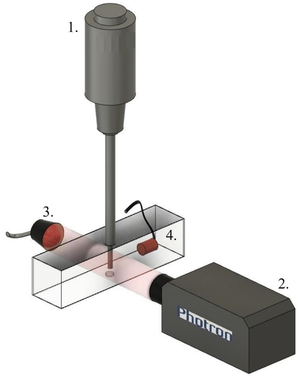 | ||
| Fig. 1 Schematic representation of the experimental setup, featuring the following components: (1) the ultrasonic horn, which was suspended in the liquid held within a custom-made tank. (2) Photron high-speed camera used to study cavitation development in the vicinity of the horn tip, with pulsed laser illumination provided via a collimator lens, (3) acoustic detection of the cavitation activity was undertaken with a shockwave passive cavitation detector, denoted by (4). | ||
The complexity and variability of these multi-bubble systems has led to a multitude of methods for studying the cavitation phenomena. Amongst the most common are sonochemiluminescence (SCL),6,20,21 whereby light emitted from sonochemically produced hydroxyl radicals can be visualised by a camera. This allows a mostly qualitative characterisation of the cavitation region. Several studies utilise high-speed imaging (HSI) to directly observe cavitation activity, which at sufficiently high frame rates, allow bubble dynamics to be resolved.10,12,22–25 The acoustic emissions generated by the cavitation can also be monitored with some form of cavitation detector or hydrophone.
The most noticeable feature of the cavitation signal detected by the hydrophone is the bubble collapse shockwave (BCSW), emitted from the inertially cavitating collapse of the bubble cloud.26,27 This shockwave produces a sharp voltage spike in the emissions signal detected by the hydrophone at regular intervals determined by the duration (period) between successive collapses. Intuitively, a greater cavitation activity is associated with a greater amplitude and number of BCSW spikes. Hence, monitoring of the shockwave content within a cavitating liquid is a simple and reliable indicator of the overall effectiveness of the system, with respect to input parameters such as power. This has previously been demonstrated in water,25 whereby the shockwave content as a function of input power was used to determine potentially advantageous and detrimental input powers at which the cavitation generated was more and less efficient, respectively. Whilst the majority of literature involving cavitation under an ultrasonic horn focuses on a single liquid medium of water, some studies have investigated cavitation in viscous liquids at limited input powers.5,23,24 We have recently reported the analysis of shockwave content as a metric for identifying optimal input powers in ethaline for sonoprocessing of printed circuit boards.10 With a growing interest in the utilisation of high-power ultrasound for enhancement of sonoprocessing in viscous liquids such as DESs, there is a clear benefit to characterising the cavitation behaviour in these liquids across a broad range of input powers, to identify optimal parameters for enhancing sonochemical processes.
The principal objective of this study is therefore to characterise the cavitation development and activity in three DESs of varying viscosity and water, as a function of ultrasonic horn input power. HSI of the cavitation activity, with parallel acoustic detection of the shockwave content, is presented.
2 Materials and methods
2.1 Deep eutectic solvent (DES) preparation
Three DESs were investigated in this study, ethaline, CaDES and reline. Each DES was prepared by mixing the components at 60 °C until a colourless homogenous liquid was formed. Each DES was stored in a sealed Schott bottle to limit atmospheric water ingress. The constituent components of each DES are as follows:• Ethaline – a mixture of choline chloride (ChCl) and ethylene glycol (EG) in a 1:2 ratio, with a viscosity of 37 mPa s.
• CaDES – a mixture of calcium chloride hexahydrate (CaCl2·6H2O) and EG in a 1:1 ratio, with a viscosity of 59 mPa s.
• Reline – a mixture of ChCl and urea (CH4N2O) in a 1:2 molar ratio, with a viscosity of 1750 mPa s.
All DES chemical constituents were purchased from Sigma Aldrich.
2.2 Experimental setup
Results presented were obtained with a commercially available ultrasonic horn with a power of 500 W (Ultrasonic Processor, Sonics VC-505) operating at 20 kHz through a tapered Ti probe with a 6 mm-Ø tip. The ultrasonic horn (component 1, Fig. 1) is manually programmed for sonication duration and input power on a control console. Input power is entered as a percentage value in 1% increments, with a maximum input power of 70% with this horn tip. The ultrasonic horn was positioned at a consistent immersion depth of 40 mm. All cavitation data was collected within the first 5 s of sonication.2.3 High-speed imaging
High-speed imaging (HSI) of the cavitation activity in the vicinity of the ultrasonic horn tip was undertaken with a Fastcam SA-Z 2100 K (Photron, Bucks UK) (component 2, Fig. 1). Illumination was provided via synchronous 10 ns laser pulses at 640 nm (CAVILUX Smart, Cavitar, Tampere Finland), coupled to a liquid light guide and a collimating lens (component 3, Fig. 1). In addition to setting the effective temporal resolution (the duration of frame capture), this illumination facilitates shadowgraphic HSI such that bubble-collapse shockwaves may be directly imaged, via refractive index variations imposed by the pressure transient of the propagating shockwave. Imaging was undertaken through a macro-lens (Milvus 100 mm f/2M, Zeiss, Oberkocken Germany), over 486 × 324 pixels, providing a spatial resolution of 39 μm per pixel. HSI was obtained at 80000 frames per second (kfps) over a duration of approximately 5 s.
2.4 Passive cavitation detection
Acoustic cavitation emission data was detected with a bespoke, in-house fabricated passive cavitation detector28 (component 4, Fig. 1). The active material in the sensor is 110 μm thick polyvinylidene fluoride (PVdF), tailored for sensitivity to bubble-collapse shockwaves. The shockwave passive cavitation detector (swPCD) used in this study has an active element 10 mm in diameter, and was mounted on an x, y, z manipulator for accurate positioning within the vessel, Fig. 1, to detect emissions orthogonally with respect to the ultrasonic horn tip.The swPCD was connected to a digital oscilloscope (Tektronix 5 series, Berkshire UK) for data collection at 25 × 106 samples per s. Acoustic emissions were recorded for a total duration of 200 ms, triggered approximately 4 s into the sonication. Emission data was collected in millivolts (mV), as detected by the swPCD. A filtering protocol was applied to reduce noise (low-pass < 10 MHz) and direct source frequency (f0, high-pass > 20 kHz), revealing shockwave content for presentation in the voltage–time domain. Time-averaged shockwave content is quantified by the root mean square of the voltage (VRMS), over five 200 ms samples per input power, for all powers sampled.
2.5 Data collection
Sonications were initiated manually from the control console of the ultrasonic horn, at defined input powers. The remaining instrumentation was synchronised via electronic triggering controlled from a signal generator (DG4102, Rigol Technologies, Beijing China). HSI and acoustic emissions for each of the three DESs and water were collected, with five captures per input power of the ultrasonic horn.3 Results and discussion
3.1 Observations of cavitation development
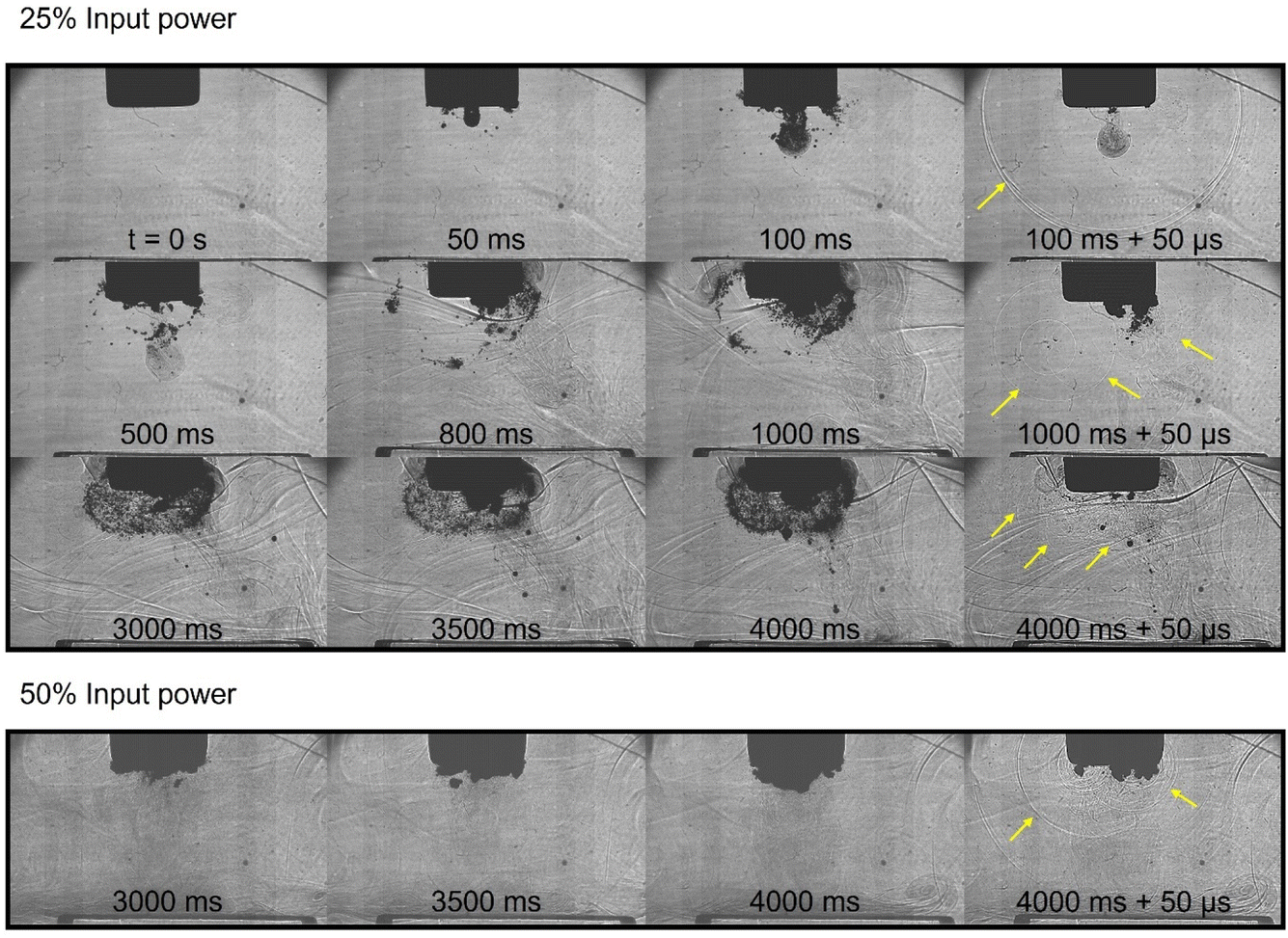
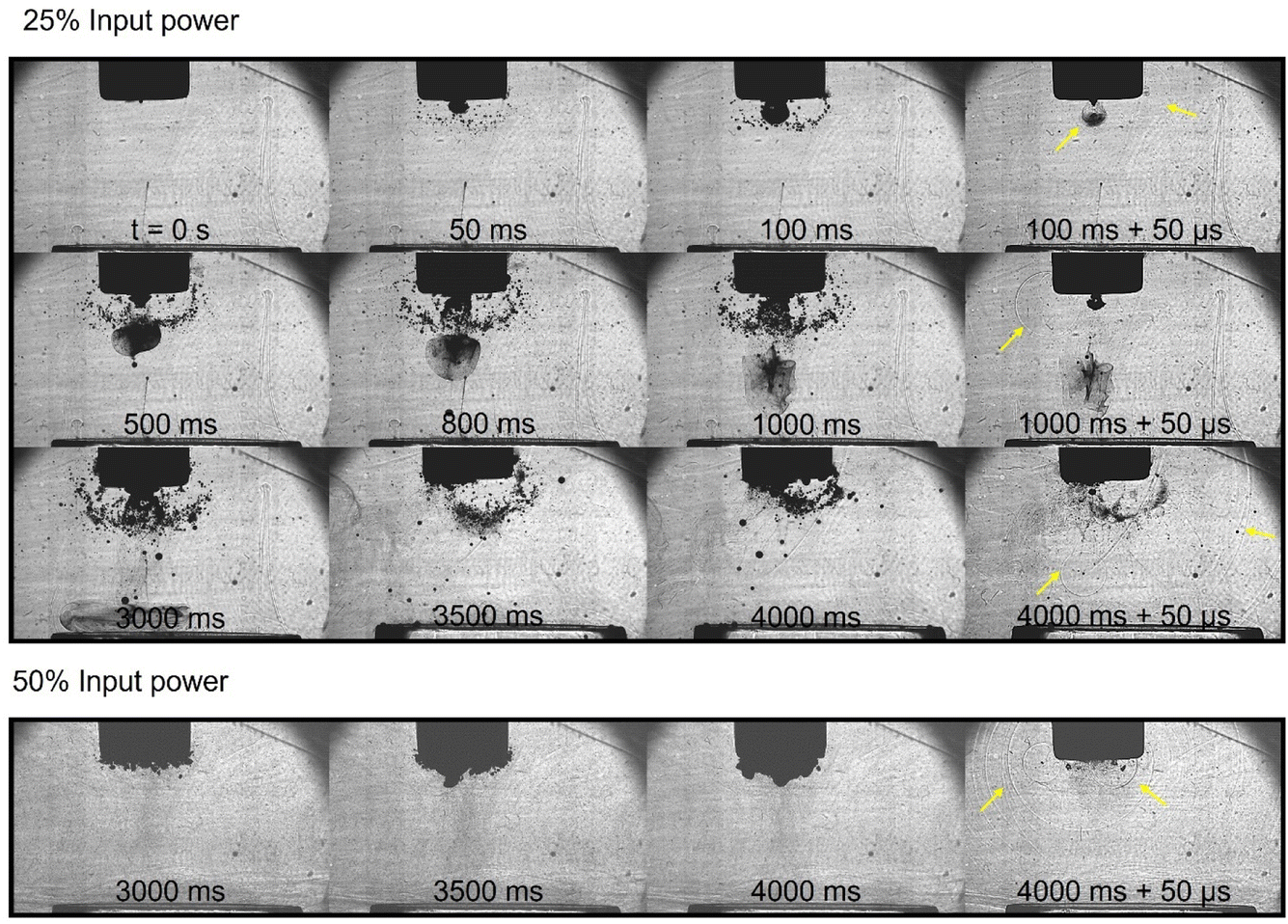
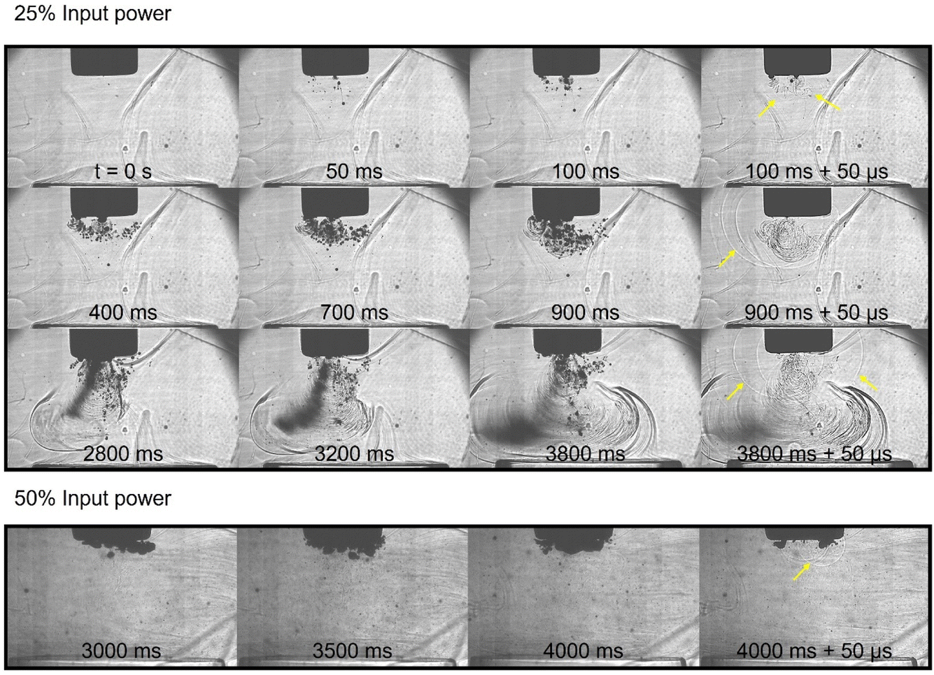
Fig. 2–5 demonstrate the differences in bubble cloud structural development in each liquid, with image sequences available in movie format as ESI.† In water, it is well documented that a cone-like bubble structure (CBS) forms near the surface of the horn tip,29–31 as observed in Fig. 2. Studies have highlighted the cavitation structure developed in DESs during sonication with an ultrasonic horn1,22 at a single given power and we recently reported structural differences in ethaline when sonicating at varied powers, for targeted delamination of metals from printed circuit boards.10 Some studies detailing the cavitation structures in high viscosity liquids such as glycerine exist6,32,33 with further studies in glycerine seeking to capture cavitation structure development.5 However, such studies are often limited to a single input power, with no indication of how cavitation characteristics vary as a function of input power. In the current study, we highlight the development of the cavitating bubble cloud in each DES (Fig. 3–5) with corresponding characterisation of the cavitation dynamics across a range of input powers. The results presented in Fig. 2–5 present bubble cloud development over the first four seconds of sonication, the final column of each figure is presented as ‘+50 μs’, equivalent to one frame of the HSI, with these respective frames presenting the bubble cloud collapse, as evident by the BCSWs represented by the arrows in yellow. It has previously been noted that BCSWs can be difficult to directly observe in highly viscous liquids due to rapid energy loss and faster propagation.23 We observe BCSWs in all liquids, whilst they do appear slightly less noticeable in the viscous liquids compared to water.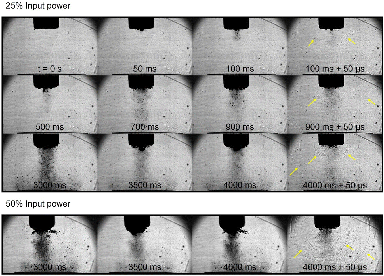 | ||
| Fig. 2 Representative high-speed imaging of the cavitation development in deionised water at 25% input power over a 4 s sonication with additional representative high-speed imaging of the fully developed cavitation at 50% input power. Bubble collapse shockwaves captured by the shadowgraphic imaging are shown with yellow arrows, and scale is provided by the 6 mm-Ø horn tip. | ||
 | ||
| Fig. 3 Representative high-speed imaging of the cavitation development in ethaline at 25% input power over a 4 s sonication with additional representative high-speed imaging of the fully developed cavitation at 50% input power. Bubble collapse shockwaves captured by the shadowgraphic imaging are shown with yellow arrows, and scale is provided by the 6 mm-Ø horn tip. | ||
 | ||
| Fig. 4 Representative high-speed imaging of the cavitation development in CaDES at 25% input power over a 4 s sonication with additional representative high-speed imaging of the fully developed cavitation at 50% input power. Bubble collapse shockwaves captured by the shadowgraphic imaging are shown with yellow arrows, and scale is provided by the 6 mm-Ø horn tip. | ||
 | ||
| Fig. 5 Representative high-speed imaging of the cavitation development in reline at 25% input power over a 4 s sonication with additional representative high-speed imaging of the fully developed cavitation at 50% input power. Bubble collapse shockwaves captured by the shadowgraphic imaging are shown with yellow arrows, and scale is provided by the 6 mm-Ø horn tip. | ||
3.2 Observation of bubble cluster collapse characteristics at specified input powers
This results section presents swPCD data over the entire 200 ms record duration as well as a short 2 ms section of the signal for observation of the oscillation behaviour of the cavitating bubble clusters. Emissions are presented at 25% and 50% input power for each liquid, selected as these represent key regions of the VRMS plots, Section 3.3, Fig. 14, explains in detail below. Briefly, VRMS provides a quantification of the average shockwave content within a liquid, taking into account shockwave amplitude and duration between the detected shockwaves, with shockwave content being a strong indicator of inertial cavitation. The structure of this VRMS plot can therefore be used as a simple but effective guide to selecting the optimal input power for any sonochemical process that is mediated by inertial cavitation.10,25In ethaline and CaDES, 25% represents the input power beyond which a significant dip in shockwave content was observed. 50% represents the input power at which the VRMS is approximately equivalent to that observed at 25% input power. Analysis of the detailed cavitation emission signal in the voltage–time domain, with corresponding HSI sequences elucidates the cavitation oscillation and bubble cloud structure behaviour responsible for the corresponding VRMS plots.
 | ||
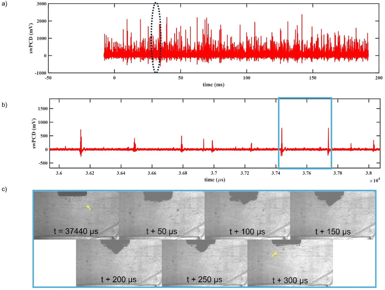
| Fig. 6 (a) 200 ms section of filtered swPCD data, recorded approximately 4 s into the 25% input power sonication in water, and (b) 2 ms of the data identified by the dashed-oval, on a shorter timescale, to reveal the bubble collapse shockwave characteristics. (c) Sample HSI extracted from single image-sequence, corresponding to the green box in (b). | ||
 | ||
| Fig. 7 (a) 200 ms section of filtered swPCD data, recorded approximately 4 s into the 50% input power sonication in water, and (b) 2 ms of the data identified by the dashed-oval, on a shorter timescale, to reveal the bubble collapse shockwave characteristics. (c) Sample HSI extracted from single image-sequence, corresponding to the blue box in (b). | ||
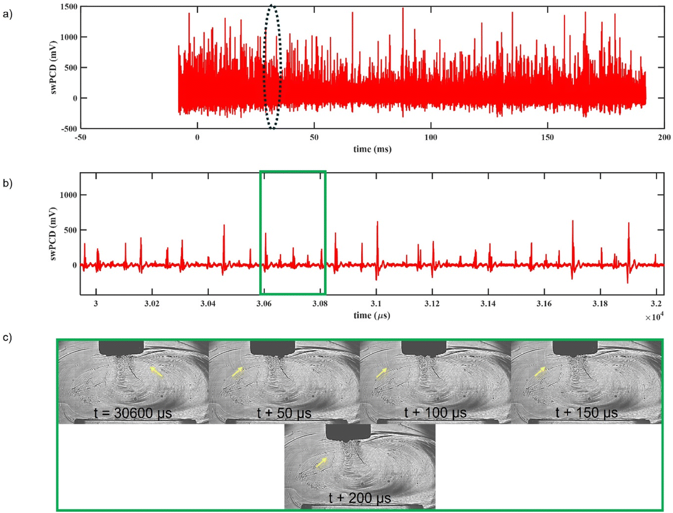
Fig. 6a and b show swPCD data of the cavitation acoustic emissions, recorded approximately 4 s into the sonication. The emission signal reveals bubble collapse shockwave content in the voltage–time domain. Fig. 6c shows representative frames of HSI of the cavitation, corresponding to the duration between detected shockwaves, indicated by the green box in Fig. 6b, with shockwaves shown with the yellow arrows. The key characteristics of the shockwave emission signal generated are the duration between detected shockwaves (also known as the periodicity of the shockwaves) and how that duration relates to the frequency of the driving ultrasound. Here, at 25% input power in water, the timings between the shockwaves are predominantly ∼200 μs, as indicated in Fig. 6b and c, or 4T0 (where T0 is the oscillation period of the driving ultrasound ≈50 μs at a frequency of 20 kHz). At this power, the cavitating bubble cloud is producing bubble collapse shockwaves every four acoustic cycles.25 Between these collapses, the bubble cloud grows and partially deflates every cycle, during the compression and rarefaction phases, but without sufficient energy to collapse. On the fourth cycle, however, the cavitation cloud reaches a large, unstable size and violently collapses, producing the detected shockwave.
Fig. 7 presents equivalent cavitation emission data for water at 50% input power. As can be observed in Fig. 7a and b, the period between the detected shockwaves has now increased to 300 μs, or 6T0. Effectively, the increase in input power has resulted in the cavitating bubble cloud to oscillate and grow to an unstable size over a longer period of time, 100 μs (or two cycles) longer in this case. As a consequence of growing for a longer duration before collapse, the amplitude of the detected shockwaves has also increased by approximately double (from around 500 mV to around 1000 mV). The average VRMS of the shockwave emissions signal at 25% and 50% input power are 40 mV and 59 mV, respectively.
 | ||
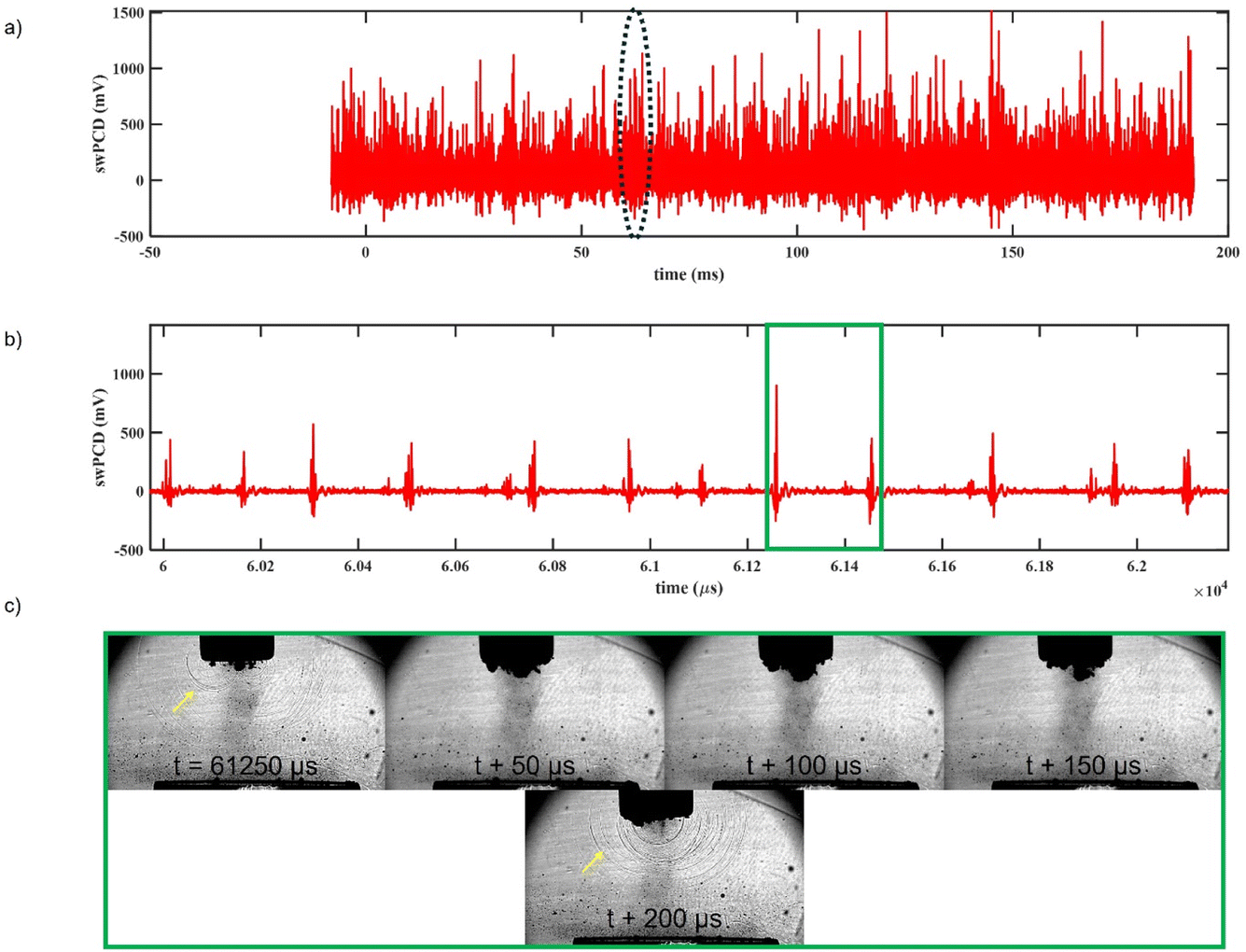
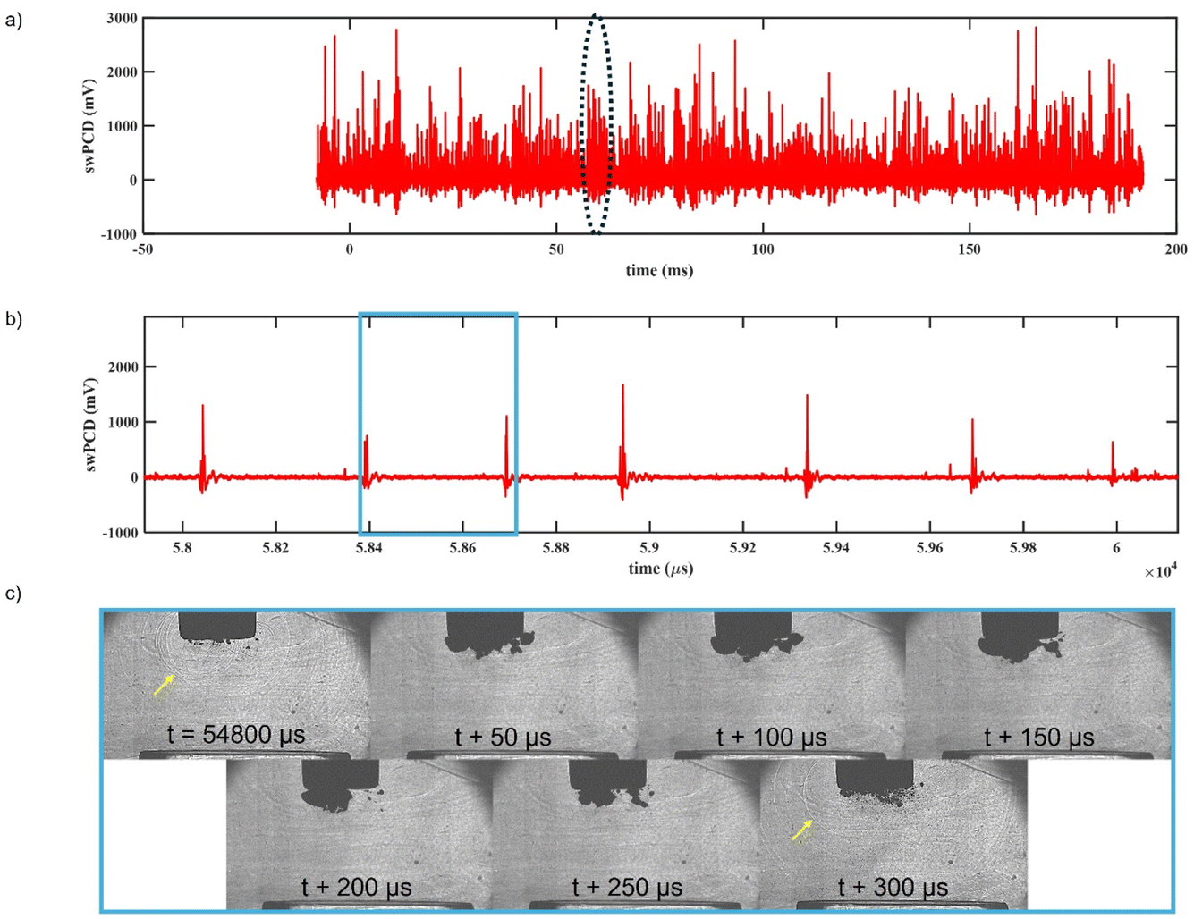
| Fig. 8 (a) 200 ms section of filtered swPCD data, recorded approximately 4 s into the 25% input power sonication in CaDES, and (b) 2 ms of the data identified by the dashed-oval, on a shorter timescale, to reveal the bubble collapse shockwave characteristics. (c) Sample HSI extracted from single image-sequence, corresponding to the green box in (b). | ||
The acoustic cavitation emissions in CaDES at 25% input power are notably different to that of water at the same power. As indicated by Fig. 8b, shockwave emissions are detected every 50 μs or T0 (every acoustic cycle). Fig. 8c supports the acoustic measurements with faint shockwaves represented with yellow arrows, every cycle. Interestingly, these shockwaves are emitted from all around the bulbous cavitation cloud previously identified in Section 3.1, Fig. 4, and characteristic of CaDES and ethaline at lower input powers. These shockwaves are regularly detected every cycle and with amplitudes typically under 500 mV. Additionally, within the bulbous cavitation cloud identified, there appears to be a larger bubble cluster attached to the ultrasonic horn tip which closer resembles that observed in water. This cluster appears to oscillate and partially deflate every cycle. As with water, this bubble cluster violently collapses after a number of cycles. The green box of Fig. 8b with corresponding HSI sequences of Fig. 8c shows slightly larger amplitude shockwaves with a periodicity of 200 μs, which appear to correlate to a larger bubble cluster collapse alongside the regularly (T0) collapsing smaller bubbles encompassing the bulbous bubble cloud. Effectively, the cavitation collapse in CaDES occurs more regularly than in water, with similar amplitude shockwaves from more individual sources, and higher amplitude shockwaves are observed corresponding to larger bubble cluster collapse over increased durations. Thus, giving a higher average VRMS of the shockwave emissions signal of 58 mV.
Fig. 9 presents acoustic emission data and the corresponding HSI frames for CaDES at 50% input power.
 | ||
| Fig. 9 (a) 200 ms section of filtered swPCD data, recorded approximately 4 s into the 50% input power sonication in CaDES, and (b) 2 ms of the data identified by the dashed-oval, on a shorter timescale, to reveal the bubble collapse shockwave characteristics. (c) Sample HSI extracted from single image-sequence, corresponding to the blue box in (b). | ||
As can be observed in Fig. 9b and c, the period between detected shockwaves is now approximately 300 μs or 6T0, which is the same as that observed in water. The average shockwave amplitude is around 1000 mV, with the average VRMS of the shockwave emissions signal 54 mV. The structure of the cavitation is reminiscent of water, with a characteristic CBS that grows over several acoustic cycles, as previously discussed. Shockwave emissions are generated from a large primary bubble cluster as opposed to several collapses across multiple bubbles (like that observed at 25% input power). Whilst the individual shockwaves are larger in amplitude compared to 25% input power, they occur less frequently (with the bubble cloud taking 6 times longer to collapse). Additionally, the cavitating volume is limited to the region directly attached to the distal end of the ultrasonic horn tip as opposed to the larger volume bulbous cloud developed at 25% input power. At these two selected input powers, overall cavitation intensity as indicated by the VRMS, is approximately equivalent, despite the 25% greater input power applied to the ultrasonic horn.
 | ||
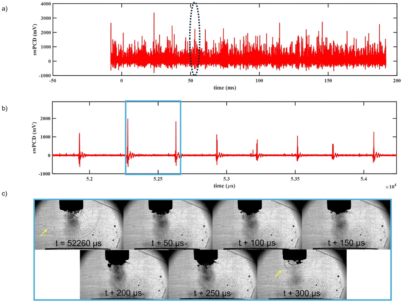
| Fig. 10 (a) 200 ms section of filtered swPCD data, recorded approximately 4 s into the 25% input power sonication in ethaline, and (b) 2 ms of the data identified by the dashed-oval, on a shorter timescale, to reveal the bubble collapse shockwave characteristics. | ||
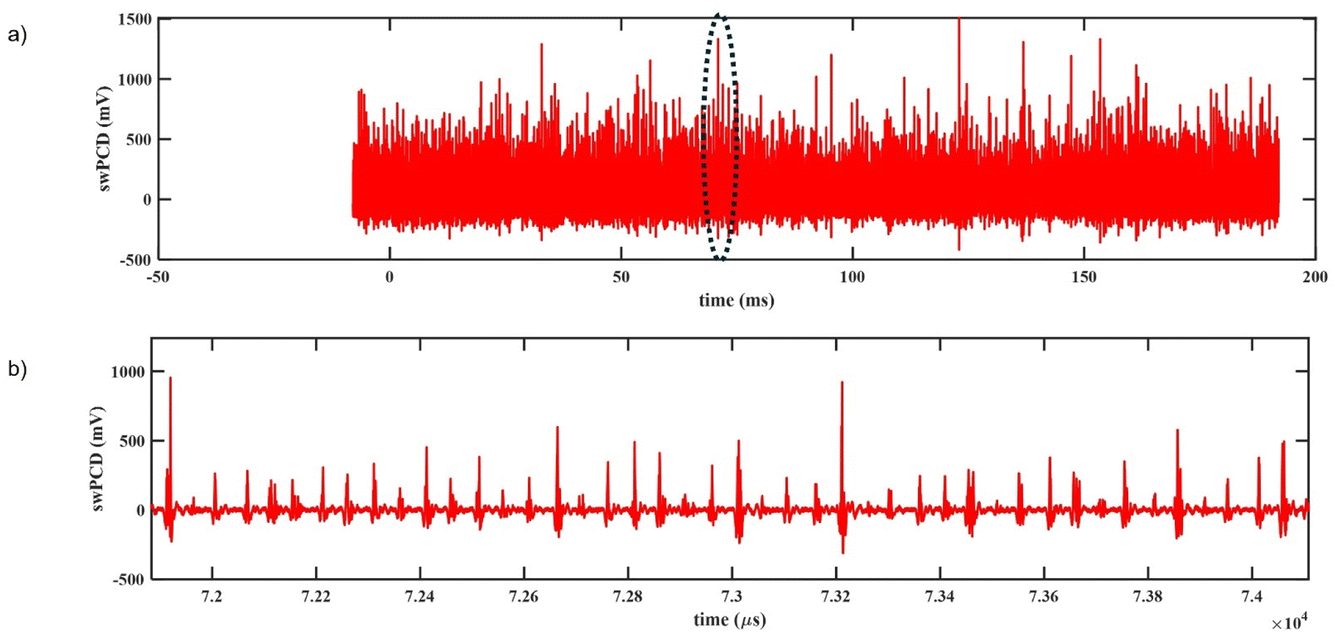
As with CaDES, at 25% input power ethaline is primarily dominated by T0 shockwaves generated from bubble collapses all around the bulbous cavitating cloud of Fig. 3, every 50 μs. As with CaDES, there appears to be variation in shockwave amplitude associated with larger bubble collapses from within the bulbous cavitating cloud over successive cycles. The average amplitude of the shockwaves is below 500 mV, equivalent to that observed in both water and CaDES at 25% input power. This gives an average VRMS of the shockwave emissions signal of 59 mV.
At 50% input power, Fig. 11, the cavitation oscillation period is again equivalent to that of water and CaDES at approximately 300 μs. The average shockwave amplitude is around 1000 mV giving an average VRMS of 55 mV. Again, the cavitating bubble cloud closely resembles the CBS of water, as shown previously in Fig. 3.
 | ||
| Fig. 11 (a) 200 ms section of filtered swPCD data, recorded approximately 4 s into the 50% input power sonication in ethaline, and (b) 2 ms of the data identified by the dashed-oval, on a shorter timescale, to reveal the bubble collapse shockwave characteristics. | ||
 | ||
| Fig. 12 (a) 200 ms section of filtered swPCD data, recorded approximately 4 s into the 25% input power sonication in reline, and (b) 2 ms of the data identified by the dashed-oval in (a), on a shorter timescale, to reveal the bubble collapse shockwave characteristics. (c) Sample HSI extracted from single image-sequence, corresponding to the green box in (b). | ||
 | ||
| Fig. 13 (a) 200 ms section of filtered swPCD data, recorded approximately 4 s into the 50% input power sonication in reline, and (b) 2 ms of the data identified by the dashed-oval in (a), on a shorter timescale, to reveal the bubble collapse shockwave characteristics. (c) Sample HSI extracted from single image-sequence, corresponding to the blue box in (b). | ||
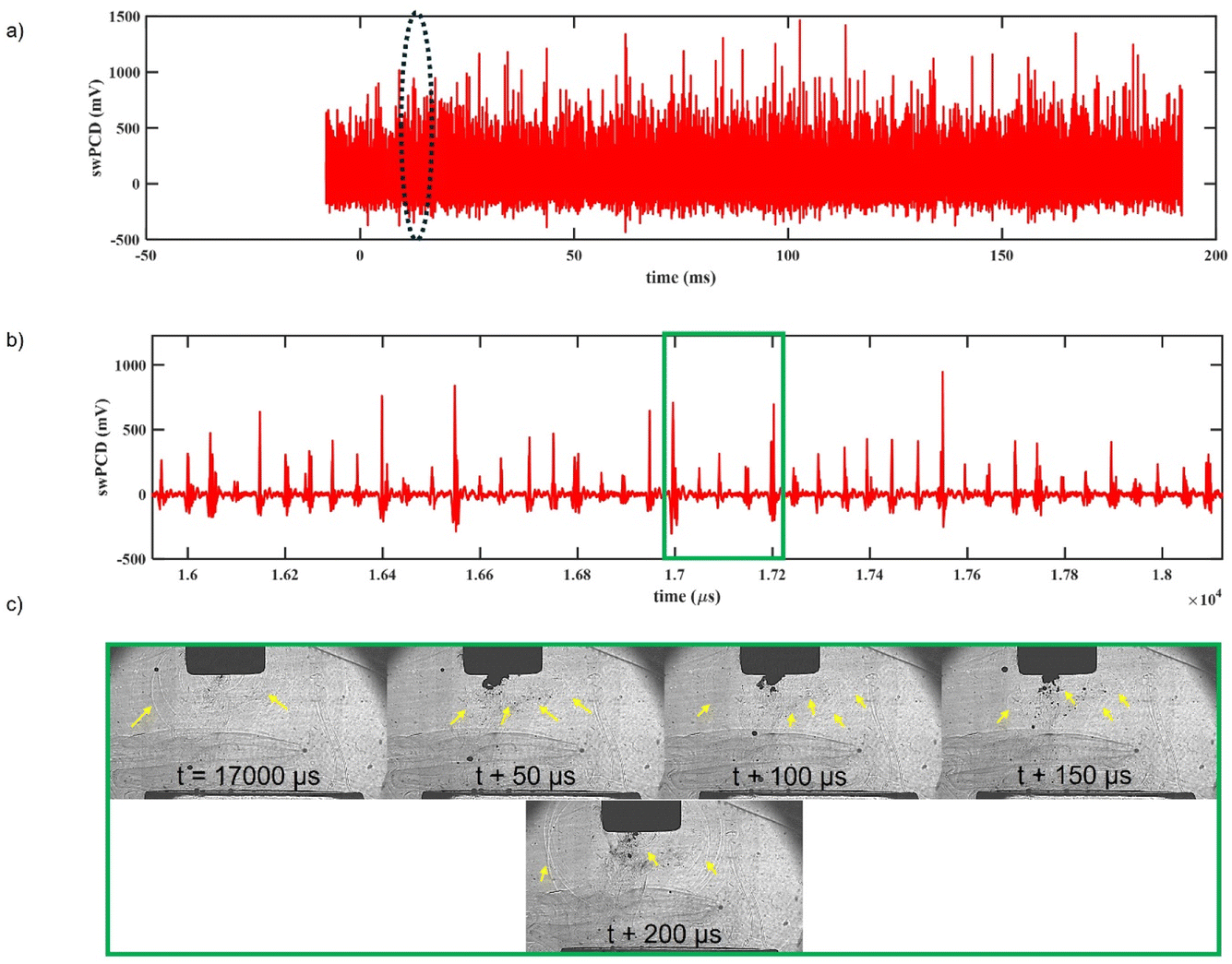
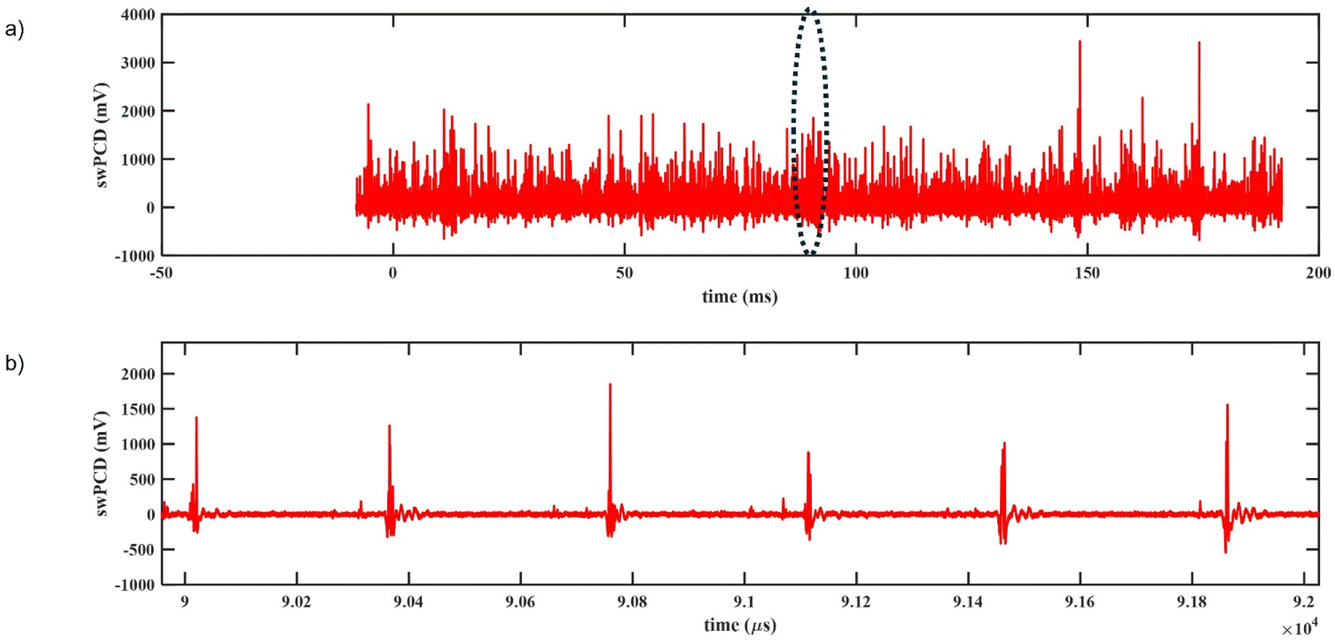
As with the previous DESs at 25% input power, reline is primarily dominated by T0 shockwaves generated from bubble collapses all around the bulbous cavitating cloud of Fig. 4 every 50 μs. The amplitude of these emissions are suppressed compared to each of the previous solutions with an average value of lower than 400 mV. This can be correlated both to the size of the cavitating region under the horn tip being reduced in reline, compared to the previous DESs (Fig. 4) as well as the viscous media rapidly attenuating the energy of the shockwaves.23 Where the source of BCSWs in the previous DESs can be observed to be generated from all across the bulbous cloud structure developed, in reline the shockwaves appear to be generated more localised to the distal end of the horn tip (Fig. 12c). In reline, the mean VRMS at 25% input power is approximately 42 mV.
As can be observed in Fig. 13b and c, the period between detected shockwaves in reline is now approximately 300 μs or 6T0, which is the same as that observed in the previous liquids. However, we observe the irregular presence of shockwaves over smaller periods, associated with satellite bubble clusters collapsing more regularly than the large primary cluster (Fig. 13b). The average shockwave amplitude is greatly suppressed with regularly detected BCSWs not exceeding 500 mV. The structure of the cavitating cloud is more reminiscent of water (Fig. 13c) with the viscosity of reline suppressing bubble collapse, reducing the amplitude BCSWs emitted from the primary bubble cluster over several cycles. At 50% input power, the average VRMS of the shockwave emissions signal is approximately 40 mV.
3.3 Characterisation of the cavitation activity in each liquid across a range of input powers
In this results section, swPCD data at incremental powers from 20% to 70% are presented for each liquid. The root mean square voltage, VRMS, for the signal collected during each sonication, is taken to quantify the time averaged shockwave content within the signal. Fig. 14 represents the mean VRMS over the five sonications, with error bars representing the standard deviation. This method has previously been reported in detail by Yusuf et al.25 in water under a 450 W ultrasonic horn and also in ethaline for the purpose of optimising cavitation output for printed circuit board delamination.10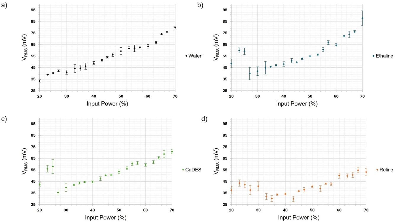 | ||
| Fig. 14 Mean VRMS from five 200 ms sonications at each ultrasonic horn input power, detected by the swPCD during sonications in (a) water, (b) ethaline, (c) CaDES and (d) reline. | ||
Fig. 14a presents the VRMS plot for water. Full details regarding the structure of this plot are given in Yusuf et al.25 Briefly, with increasing input power of the ultrasonic horn there is a general increase in VRMS, caused by an increasing amplitude of the bubble collapse shockwaves due to increased size of the bubble cluster, observable in Fig. 2. However, as indicated in Fig. 14a, there are regions of dips or plateau, whereby increasing power of the ultrasonic horn does not correlate with an increase in VRMS. In water, there are plateaus observed around 30% and 50–60% input power. As described in Yusuf et al., these dips in VRMS are due to the cavitation response transitioning from one subharmonic order to the next, effectively meaning the period between collapse increases by one acoustic cycle. For example, from 4T0 to 5T0, which appears to occur around 30% input power, in Fig. 14a we see there is a dip or plateau in VRMS associated with suppression of the cavitation emission strength due to inefficient periodicity of the bubble cloud. This phenomenon is explored in water in greater detail in ref. 25.
Fig. 14b and c present the equivalent VRMS plot for ethaline and CaDES, respectively. As can be observed, both of these liquids exhibit a very similar trend in cavitation activity over the range of powers sampled. Both DESs exhibit a dip in VRMS around 60% input power and a plateau around 40% input power. However, what is most noticeable is the sharp drop in VRMS from 25% to 30% input power. From the emission data presented in Section 3.2, this dip correlates to the input powers whereby the cavitating structure shifts from a large bulbous cloud cavitating strongly every cycle (T0) to the smaller cavitating region under the horn tip that oscillates and grows over several successive cycles.
Reline, has a uniquely different VRMS plot (Fig. 14d), exhibiting a broader dip from 30 to 50% input power, primarily associated with the greater shockwave suppression in the more viscous DES. These plots themselves give a good indicator of potentially advantageous and disadvantageous input powers to use for sonochemical applications, as they summarise the cavitation intensity during sonication by measuring the shockwave content detected in each liquid.
4 Conclusions
This study of cavitation structure development in three different DESs of increasing viscosity, and water, sonicated at 20 kHz, across a range of input powers available to a commercially available ultrasonic horn, showed that:• the development of cavitating structures in the viscous DESs is notably different than in water. The latter is well characterised in the literature by a cone-like bubble structure that oscillates and collapses due to inertia at integer periodicity dictated by the driving power. DESs, at lower input powers, develop a characteristic large bulbous cloud of oscillating bubbles, extending far beneath the ultrasonic horn tip, with inertial cavitation evident throughout this structure.
• in water, the cavitation, by measure of shockwave content in the emission signal, generally increases with increasing input power. At powers of transitioning shockwave periodicity however, cavitation is less efficient and a dip or plateau in cavitation activity is observed. In the more viscous DESs, cavitation emissions are higher at lower input powers. This is associated with the T0 periodicity of the shockwaves, generating shockwaves every acoustic cycle. Particularly noticeable in ethaline and CaDES is a sharp drop in cavitation activity, due to recession of the bulbous cavitation structure back towards the horn tip and corresponding increase in the period between shockwaves. We speculate that localised temperature variation under the ultrasonic horn tip will have an effect on the liquid viscosity of the DESs. In the most viscous DES, reline, cavitation activity is more notably suppressed due to the viscous forces limiting propagation of the shockwaves through the liquid.
• in the DESs, for this experimental arrangement, shockwave content at 25% input power is greater than, or approximately equivalent to, the shockwave content at 50% input power. Driving the ultrasonic horn at this lower power may be more beneficial for sonochemical processing applications where maximal cavitation effectiveness is a priority.
For sonochemical processing applications in any liquid, parameter optimisation is a major challenge. In this study, we have demonstrated that cavitation characterisation for optimisation within any liquid in terms of power consumption, may be easily assessed via determining the level of shockwave content within the emission signal. We speculate that bubble collapse shockwave content, as measured by VRMS, could be used to determine the most efficient delivery of power of sonication for any given liquid of ranging viscosity. This paper focuses on the sonochemical optimisation of the ultrasound in each of the studied DESs. Future work to investigate any chemical interactions in the DES systems when exposed to ultrasound, could be beneficial in further process optimisation by assessing how the chemistry of DESs are influenced by prolonged sonication.
Author contributions
Ben Jacobson: conceptualization, methodology, data curation, validation, formal analysis, investigation, writing – original draft, writing – review & editing. Shida Li: data curation, investigation. Paul Daly, resources, writing – review & editing. Christopher Elgar: investigation, writing – review & editing. Andrew Abbott: conceptualization, writing – review & editing, funding acquisition. Andrew Feeney: writing – review & editing, supervision, funding acquisition. Paul Prentice: conceptualization, methodology, writing – original draft, writing – review & editing, supervision, funding acquisition.Conflicts of interest
The authors declare that they have no known competing financial interests or personal relationships that could have appeared to influence the work reported in this paper.Acknowledgements
This work was financially supported by the SonoCat project (grant EP/W018632/1) funded by the UK Engineering and Physical Sciences Research Council (EPSRC).References
- R. Marin Rivera, et al., Ultra-fast extraction of metals from a printed circuit board using high power ultrasound in a calcium chloride-based deep eutectic solvent, RSC Sustainability, 2024, 2(2), 403–415, 10.1039/d3su00147d.
- L. Zhang and Z. Xu, A review of current progress of recycling technologies for metals from waste electrical and electronic equipment, J. Clean. Prod., 2016, 127, 19–36, DOI:10.1016/j.jclepro.2016.04.004.
- R. Marin Rivera, G. Zante, J. M. Hartley, K. S. Ryder and A. P. Abbott, Catalytic dissolution of metals from printed circuit boards using a calcium chloride–based deep eutectic solvent, Green Chem., 2022, 24(7), 3023–3034, 10.1039/d1gc04694b.
- G. Zante, R. Marin Rivera, J. M. Hartley and A. P. Abbott, Efficient recycling of metals from solar cells using catalytic etchants, J. Clean. Prod., 2022, 370, 133552, DOI:10.1016/j.jclepro.2022.133552.
- I. Tzanakis, G. S. Lebon, D. G. Eskin and K. A. Pericleous, Characterizing the cavitation development and acoustic spectrum in various liquids, Ultrason. Sonochem., 2017, 34, 651–662, DOI:10.1016/j.ultsonch.2016.06.034.
- A. Bampouli, et al., Understanding the ultrasound field of high viscosity mixtures: Experimental and numerical investigation of a lab scale batch reactor, Ultrason. Sonochem., 2023, 97, 106444, DOI:10.1016/j.ultsonch.2023.106444.
- J. L. Luque-Garcia and M. D. Luque de Castro, Ultrasound: a powerful tool for leaching, TrAC, Trends Anal. Chem., 2003, 22(1), 41–47, DOI:10.1016/s0165-9936(03)00102-x.
- M. Lamminen, Mechanisms and factors influencing the ultrasonic cleaning of particle-fouled ceramic membranes, J. Membr. Sci., 2004, 237(1–2), 213–223, DOI:10.1016/j.memsci.2004.02.031.
- D. J. Flannigan and K. S. Suslick, Plasma formation and temperature measurement during single-bubble cavitation, Nature, 2005, 434(7029), 52–52, DOI:10.1038/nature03400.
- B. Jacobson, et al., A mechanistic study identifying improved technology critical metal delamination from printed circuit boards at lower power sonications in a deep eutectic solvent, Ultrason. Sonochem., 2023, 101, 106701, DOI:10.1016/j.ultsonch.2023.106701.
- D. G. Eskin, et al., Fundamental Studies of Ultrasonic Melt Processing, presented at the Proceedings of the 6th Decennial International Conference on Solidification Processing, Windsor, 2017 Search PubMed.
- A. Priyadarshi, et al., In-situ observations and acoustic measurements upon fragmentation of free-floating intermetallics under ultrasonic cavitation in water, Ultrason. Sonochem., 2021, 80, 105820, DOI:10.1016/j.ultsonch.2021.105820.
- R. Marin Rivera, et al., Ultra-fast extraction of metals from a printed circuit board using high power ultrasound in a calcium chloride-based deep eutectic solvent, RSC Sustainability, 2024, 2, 403–415 RSC.
- R. M. Wagterveld, L. Boels, M. J. Mayer and G. J. Witkamp, Visualization of acoustic cavitation effects on suspended calcite crystals, Ultrason. Sonochem., 2011, 18(1), 216–225, DOI:10.1016/j.ultsonch.2010.05.006.
- Y. Fang, T. Yamamoto and S. Komarov, Cavitation and acoustic streaming generated by different sonotrode tips, Ultrason. Sonochem., 2018, 48, 79–87, DOI:10.1016/j.ultsonch.2018.05.011.
- T. Yamashita and K. Ando, Low-intensity ultrasound induced cavitation and streaming in oxygen-supersaturated water: Role of cavitation bubbles as physical cleaning agents, Ultrason. Sonochem., 2019, 52, 268–279, DOI:10.1016/j.ultsonch.2018.11.025.
- D. B. Rajamma, S. Anandan, N. S. M. Yusof, B. G. Pollet and M. Ashokkumar, Sonochemical dosimetry: A comparative study of Weissler, Fricke and terephthalic acid methods, Ultrason. Sonochem., 2021, 72, 105413, DOI:10.1016/j.ultsonch.2020.105413.
- G. Mark, et al., OH-radical formation by ultrasound in aqueous solution – Part II: Terephthalate and Fricke dosimetry and the influence of various conditions on the sonolytic yield, Ultrason. Sonochem., 1998, 5, 41–52 CrossRef CAS PubMed.
- N. Masuda, A. Maruyama, T. Eguchi, T. Hirakawa and Y. Murakami, Influence of Microbubbles on Free Radical Generation by Ultrasound in Aqueous Solution: Dependence of Ultrasound Frequency, J. Phys. Chem. B, 2015, 119(40), 12887–12893, DOI:10.1021/acs.jpcb.5b05707.
- I. Garcia-Vargas, O. Louisnard and L. Barthe, Extensive investigation of geometric effects in sonoreactors: Analysis by luminol mapping and comparison with numerical predictions, Ultrason. Sonochem., 2023, 99, 106542, DOI:10.1016/j.ultsonch.2023.106542.
- B. Verhaagen and D. Fernandez Rivas, Measuring cavitation and its cleaning effect, Ultrason. Sonochem., 2016, 29, 619–628, DOI:10.1016/j.ultsonch.2015.03.009.
- C. E. Elgar, et al., Using ultrasound to increase copper and nickel dissolution and prevent passivation using concentrated ionic fluid, Electrochim. Acta, 2024, 476, 143707, DOI:10.1016/j.electacta.2023.143707.
- M. Khavari, et al., Cavitation-induced shock wave behaviour in different liquids, Ultrason. Sonochem., 2023, 94, 106328, DOI:10.1016/j.ultsonch.2023.106328.
- A. Žnidarčič, R. Mettin, C. Cairós and M. Dular, Attached cavitation at a small diameter ultrasonic horn tip, Phys. Fluids, 2014, 26(2), 023304, DOI:10.1063/1.4866270.
- L. Yusuf, M. D. Symes and P. Prentice, Characterising the cavitation activity generated by an ultrasonic horn at varying tip-vibration amplitudes, Ultrason. Sonochem., 2021, 70, 105273, DOI:10.1016/j.ultsonch.2020.105273.
- L. van Wijngaarden, Mechanics of collapsing cavitation bubbles, Ultrason. Sonochem., 2016, 29, 524–527, DOI:10.1016/j.ultsonch.2015.04.006.
- F. Reuter and R. Mettin, Mechanisms of single bubble cleaning, Ultrason. Sonochem., 2016, 29, 550–562, DOI:10.1016/j.ultsonch.2015.06.017.
- K. Johansen, J. H. Song and P. Prentice, Performance characterisation of a passive cavitation detector optimised for subharmonic periodic shock waves from acoustic cavitation in MHz and sub-MHz ultrasound, Ultrason. Sonochem., 2018, 43, 146–155, DOI:10.1016/j.ultsonch.2018.01.007.
- A. Moussatov, C. Granger and B. Dubus, Cone-like bubble formation in ultrasonic cavitation field, Ultrason. Sonochem., 2003, 10(4–5), 191–195, DOI:10.1016/S1350-4177(02)00152-9.
- L. Bai, W. Xu, J. Deng, C. Li, D. Xu and Y. Gao, Generation and control of acoustic cavitation structure, Ultrason. Sonochem., 2014, 21(5), 1696–1706, DOI:10.1016/j.ultsonch.2014.02.027.
- G. Kozmus, J. Zevnik, M. Hocevar, M. Dular and M. Petkovsek, Characterization of cavitation under ultrasonic horn tip – Proposition of an acoustic cavitation parameter, Ultrason. Sonochem., 2022, 89, 106159, DOI:10.1016/j.ultsonch.2022.106159.
- N. V. Malykh and G. N. Sankin, Stabilization and acoustic spectra of a cavitation cluster in an ultrasonic spherical cavity, Tech. Phys., 2010, 55(1), 92–97, DOI:10.1134/s1063784210010159.
- V. N. Skokov, V. P. Koverda, A. V. Reshetnikov and A. V. Vinogradov, fluctuations under acoustic cavitation of liquids, Phys. A, 2006, 364, 63–69, DOI:10.1016/j.physa.2005.09.045.
- I. Garcia-Vargas, L. Barthe, P. Tierce and O. Louisnard, Simulations of a full sonoreactor accounting for cavitation, Ultrason. Sonochem., 2022, 91, 106226, DOI:10.1016/j.ultsonch.2022.106226.
- K.-M. Quan, The Bjerknes forces and acoustic radiation energy, in Energy Aspects of Acoustic Cavitation and Sonochemistry, 2022, pp. 99–109 Search PubMed.
- F. Reuter, S. Lauterborn, R. Mettin and W. Lauterborn, Membrane cleaning with ultrasonically driven bubbles, Ultrason. Sonochem., 2017, 37, 542–560, DOI:10.1016/j.ultsonch.2016.12.012.
- D. Krefting, R. Mettin and W. Lauterborn, High-speed observation of acoustic cavitation erosion in multibubble systems, Ultrason. Sonochem., 2004, 11(3–4), 119–123, DOI:10.1016/j.ultsonch.2004.01.006.
- N. C. Eddingsaas and K. S. Suslick, Evidence for a Plasma Core during Multibubble Sonoluminescence in Sulfuric Acid, J. Am. Chem. Soc., 2007, 129, 3838–3839 CrossRef CAS PubMed.
- A. Thiemann, F. Holsteyns, C. Cairos and R. Mettin, Sonoluminescence and dynamics of cavitation bubble populations in sulfuric acid, Ultrason. Sonochem., 2017, 34, 663–676, DOI:10.1016/j.ultsonch.2016.06.013.
Footnote |
| † Electronic supplementary information (ESI) available. See DOI: https://doi.org/10.1039/d4fd00031e |
| This journal is © The Royal Society of Chemistry 2024 |