 Open Access Article
 This Open Access Article is licensed under a
 Creative Commons Attribution 3.0 Unported Licence
Stability and structure of the aqueous LiTFSI–LiCl interface†
Hannah O.
Wood
,
Hannah M.
Burnett
,
Robert A. W.
Dryfe
 and
Paola
Carbone
*
and
Paola
Carbone
*
Department of Chemistry, University of Manchester, Oxford Rd, Manchester, UK. E-mail: paola.carbone@manchester.ac.uk; hannah.wood-4@postgrad.manchester.ac.uk
First published on 19th April 2024
Abstract
It has recently been demonstrated that aqueous lithium bis(trifluoromethanesulfonyl)imide (LiTFSI) and lithium chloride (LiCl) solutions can form stable liquid–liquid biphasic systems when both electrolyte phases have sufficiently high concentrations. In this work, we combine molecular dynamics simulations and experimental analysis to investigate what drives the formation of the interface and how the interfacial molecular structure correlates with its thermodynamic stability. We observe that at the liquid–vapour interface, TFSI− anions exhibit surfactant-like properties, leading to a reduction in surface tension and an increase in interfacial thickness. In contrast, the interfacial stability of the LiTFSI–LiCl biphasic systems increases with the concentration of both salts, as evidenced by the increasing surface tension and decreasing interfacial thickness. The opposing effects that the ionic concentration has on the thermodynamic stability of the different interfaces are linked to the anions' interfacial adsorption/desorption, which in turn affects the number and strength of water–water hydrogen bonds, the interfacial molecular structure and the diffusion of cations across the interface. Finally, calculations and experiments indicate that the liquid–liquid separation is driven primarily by the concentration of LiCl, and is the result of a ‘salting out’ effect.
1 Introduction
Aqueous biphasic systems (ABSs), also known as aqueous two-phase systems (ATPSs), form when the addition of solutes causes an aqueous solution to separate into discrete phases. Such systems are ubiquitous in nature,1 but also exist as synthetic mixtures,2–5 and have applications in extraction, separation,6 and purification6 processes. ABSs based on lithium salts have shown promising properties as electrolytes in the development of sustainable, high-performance aqueous lithium-ion batteries,7–9 and as a membrane-free solution in redox flow batteries to prevent species crossover between the electrolytes in each half-cell.10–12 Alongside the growing interest in ABSs, aqueous electrolytes are receiving attention as an alternative to organic electrolytes, driven by their safety, cost-effectiveness, and higher ionic conductivity. Nonetheless, a significant limitation is the lower energy densities of aqueous systems, attributed to their narrow electrochemical stability windows compared to organic counterparts.13Historically, research into aqueous electrolytes has predominantly focused on a limited concentration regime near 1 molar (M), driven by the pursuit of ideal electrodics and optimum conductivity. However, in recent years, water-in-salt (WiS) electrolyte systems have emerged as a distinct class of electrolytes with several unique properties. Unlike traditional aqueous electrolytes, in WiS solutions the dissolved salts outnumber the water molecules by volume or weight.14 WiS electrolytes possess distinct physicochemical properties, including exceptional thermal stability, wider electrochemical stability windows, and enhanced cation transport properties when compared with conventional electrolytes.15–17 Moreover, the high concentration of salts in WiS electrolytes leads to changes in ion solvation, ion pairing, and interfacial/interphasial phenomena.18 WiS solutions containing lithium bis(trifluoromethanesulfonyl)imide (LiTFSI) are particularly promising for electrochemical applications.14,19 These systems possess several interesting properties: aqueous solutions of >20 molal (m) LiTFSI were observed to significantly expand the electrochemical stability window, extending it to 3 V, compared with the thermodynamic stability window of 1.23 V in pure water. This was attributed to the removal of traditional water clusters in the WiS regime, thereby reducing water reactivity.20 Additionally, the formation of a solid electrolyte interphase at the electrode surface, due to bulky fluorinated anions, acts to prevent water reduction and side reactions.14,21,22 The mesoscopic structure of LiTFSI WiS solutions remains an area of active research. Borodin et al. proposed that super-concentrated aqueous LiTFSI solutions (10–21 molal) contain heterogeneous nanodomains due to cation solvation disproportionation.17 It was reported that these systems consist of two distinct domains: a non-aqueous phase containing TFSI− ions coordinated with some Li+, and an aqueous phase comprising fully solvated Li+ in water. The observed clustering of CF3 groups in WiS LiTFSI solutions suggests that the presence of hydrophilic (OS–N–SO) and hydrophobic (CF3) groups in the TFSI− anion may be a contributing factor to the segregation of water-rich and anion-rich domains.23 More recently, nano-structuring has been observed in several other WiS systems.24–32 This structuring differs from that of superionic glasses and ceramics, as evidenced by the long-range disorder and dynamic nature. Consequently, WiS solutions can be considered an intermediate concentration regime in the transition from a dilute solution to an ionic liquid.
The intersection of ABSs and WiS solutions presents a novel research front. It has recently been shown that mixtures of two aqueous monovalent WiS solutions consisting of a common cation, but with different anions, form ABSs over a wide range of compositions at room temperature.5 However, the mechanisms governing the phase separation are still not fully understood. Bridges and coworkers4 suggested that the combination of two salts in water, one with a kosmotropic (water-structuring) anion and the other with a chaotropic (water-destructuring) anion, can induce phase separation. However, Dubouis et al., found that an ABS exists between WiS solutions of lithium chloride (LiCl) and LiTFSI, with viscosity measurements indicating that both salts are kosmotropic. They concluded that the dominant factor for phase separation in salt–salt solutions is the size asymmetry between anions.33 It is worth noticing, however, that viscosity-based methods for classifying kosmotropes and chaotropes have since been criticised, with Chialvo and Crisalle noting that Jones–Dole's B coefficient-based criteria cannot be taken as reliable structure-making/breaking descriptors due to their lack of a direct link to solute-induced solvent microstructural perturbations.34
In this work, we investigate the driving forces behind phase separation in LiTFSI–LiCl ABSs, which form primarily in the WiS regime. We start with an analysis of several aqueous LiTFSI liquid–vapour interfaces, to gain insight into the behaviour of the constituent species. Subsequently, we investigate how concentration and liquid structure affect the interfacial properties and thermodynamic stability of LiTFSI–LiCl ABSs. Through this approach, we aim to shed light on the fascinating microscopic behaviour of these systems, contributing to the broader understanding, for use in electrochemical applications and beyond.
2 Methodology
2.1 Computational details
The molecular dynamics (MD) simulations were performed using the GROMACS 2018.4 software package.35 The velocity-Verlet algorithm36 was used to integrate the positions of atoms through time. To avoid ion clustering at concentrations lower than the solubility limit, the interaction potentials between Li+ and Cl− ions were modelled using the Madrid-2019 force field,37 which employs scaled ionic charges of ±0.85e. The TIP4P/2005 model was used to model water,38 and TFSI− ions were modelled using the AMBER force field.39,40 To ensure electroneutrality, the partial electronic charges of TFSI− ions were scaled to sum to −0.85e. The force-field parameters are reported in Table S1.† To our knowledge, this study represents the first application of the AMBER force field with scaled charges for TFSI− ions. The particle-mesh Ewald (PME) summation method was used for long-range electrostatics with a Fourier spacing of 0.16 nm. A short-range electrostatics cutoff of 1.2 nm and a Lennard Jones cutoff of 1.2 nm were used. The LINCS algorithm was used for all bond constraints, and periodic boundary conditions were employed in all three spatial dimensions to mimic the bulk and macroscopic properties of the system.Initial configurations of all systems were generated using Packmol.41 To validate the force-field choices, simulations were conducted for each bulk electrolyte in 5 × 5 × 5 nm cubic boxes, and properties from these systems were compared with experimental data. For the interfacial systems, a rectangular parallelepiped simulation cell was used.42 To check possible finite-size effects, simulations were performed using two box sizes of 5 × 5 × 16 nm and 10 × 10 × 30 nm for the liquid–vapour and 5 × 5 × 10 nm and 10 × 10 × 20 nm for the liquid–liquid systems. The results confirmed that the different box sizes yielded consistent results. Liquid–liquid simulations were created with symmetric concentrations of electrolytes ranging from 10 to 20 molal. Energy minimisation was performed using the steepest-descent algorithm. NVT and NPT equilibrations were performed before an NVT production simulation. The Nosè–Hoover thermostat set to 294.14 K and Parrinello–Rahman barostat set to 1 atm were used to maintain constant temperatures and pressures, respectively. The concentrations, numbers of particles, box sizes, and respective simulation lengths for each liquid–vapour system are presented in Table S2,† and those for each biphasic system are presented in Table S3.† Due to the high viscosity of WiS solutions and large system sizes used, very long simulation times were required for some systems to ensure proper equilibration and sampling of the relevant properties. Equilibrium was determined by the convergence of several properties, such as mass densities in each bulk phase and the interfacial tension.
2.2 Experimental details
Lithium chloride (anhydrous) was purchased from Alfa Aesar. Lithium bis(trifluoromethanesulfonyl)imide was purchased from Fluorochem Limited. All reagents were used as received. In a previous study by Dubouis et al.,5 ABSs of LiTFSI and LiCl were prepared by first combining the solid salts required to achieve the desired concentrations of each solution upon addition of a certain mass of water. The ABS forms spontaneously, with the water separating between the phases; as a result, the true concentration of each phase cannot be accurately known and is likely to be far greater than the concentration reported. In contrast, the biphasic systems in this work were prepared by first making solutions of each salt separately at the target concentration, and then combining the two solutions to form an ABS. This approach enables the volume and concentration of each phase to be controlled and known more accurately. It must be noted that ions may still partition between the two phases; this is discussed further in Section 3.3. Using this approach, unequal volumes of each solution can be combined; when an ABS with asymmetric volumes of each phase was formed, there was no obvious volume change for either phase over time, suggesting that there was little or no transfer of water between phases. Even after shaking and reforming the interface, the phases separated back into their original volumes.Density measurements were made by determining the mass of 1 mL of the relevant solution. The measurements were recorded five times for each solution to find the average and standard deviation of the masses. All density measurements in this report were taken at 294.15 K. An Attension Theta Optical Tensiometer was used to measure the surface tension using the pendant drop method. All surface tension measurements were taken at 293.15 K and the tensiometer calibration was checked using deionised water beforehand. To perform the liquid–vapour interface measurements, a syringe with a flat-tipped 18G needle attached was filled with a small amount of the sample solution (approx. 0.3–0.5 mL). The syringe was mounted in a holder on the tensiometer and adjusted so that the tip of the needle could be seen by the optical camera of the tensiometer. The syringe plunger was then depressed until a drop of the solution was hanging from the tip of the needle. OneAttension software was used to record the movement of the drop at 32 frames per second for 10 seconds using the optical camera; the density of the heavy and light phases (in this case air was the light phase) was used to analyse the drop shape and thereby calculate surface tension. The drop baseline was the tip of the flat needle and was identified automatically for most measurements but was set manually if the drop was not as defined, for example when the surface tension was low (below 30 mN m−1). At least five measurements were taken for each solution and the average and standard deviation of these measurements were calculated for each WiS electrolyte. To perform the liquid–liquid interface measurements, the same procedure was followed as for the liquid–vapour interface measurements except the needle tip was submerged in a second solution in a quartz cuvette. For LiTFSI and LiCl interface measurements, the syringe was filled with LiTFSI (heavy phase) and the cuvette was filled with LiCl (light phase).
3 Results and discussion
3.1 Bulk properties
The density values obtained from the bulk systems of 1, 3, 6, 10, 13, 16 and 20 molal LiTFSI and LiCl aqueous salt solutions are reported in Fig. S1(a) and (b) of the ESI,† respectively. The results are compared with experimental values measured under the same conditions. As expected, the mass densities increase with increasing concentration of salt for both LiCl and LiTSFI systems. For solutions of LiCl, all calculated densities were found to be within 4% of the experimental data, with calculated values slightly below the corresponding experimental values. These results indicate that the sizes of the Li+ and Cl− ions are well-captured by the Madrid force-field parameters. Calculated densities for the aqueous LiTFSI systems were also in excellent agreement with experimental results, with a maximum deviation of 5%, suggesting that our modified AMBER force field captures the size of TFSI− ions well.The structure of the bulk electrolyte phases was analysed by calculating the radial distribution functions (RDFs). For the simulations of LiCl solutions at 1, 10, and 20 molal concentrations, the Li–Cl, Li–O, and Cl–H RDFs can be found in Fig. S2 of the ESI.† Li–O and Li–Cl coordination numbers (CNs), presented in Table S4 of the ESI,† were obtained by integrating the corresponding RDFs within the first Li+ coordination shell, corresponding to a radius of 0.25 nm from the ion. Our results are consistent with previous findings: Li+ ions exhibit a well-defined solvation shell in the Li–O RDFs for the 1 and 10 molal systems, and the Li+–water CN is 4.37,43–45 As the LiCl concentration is increased from 1 to 20 molal, the Li–O coordination number decreases from 3.999 to 3.496. The Li–Cl RDF of the 20 molal system exhibits a sharp peak at a distance of 0.25 nm, indicating a strong association between Li+ and Cl− ions in the most concentrated system. Moreover, the Li–Cl CN increases from 0 in the 1 molal system to 0.159 in the 20 molal system, indicating the formation of contact ion pairs (CIPs) in the more concentrated systems.
RDFs between several atom types were calculated for the 1, 10, and 20 molal LiTFSI solutions, and are presented in Fig. 1, where the subscripts “T” and “W” denote atoms in TFSI− and water, respectively. The Li-TFSI CN was determined using the methodology outlined by Borodin et al.,17 where the upper-bound estimate assumes CIP formation if the Li+ ion is within a 0.5 nm radius of the TFSI− nitrogen atom, and the lower-bound estimate assumes CIP formation if the Li+ ion is within a 0.27 nm radius of the TFSI− oxygen. This approach accounts for the expanded first coordination shell of Li+ when coordinated with bulkier species. The Li-TFSI CNs and Li–water CNs are presented in Table 1. Sharp peaks at 0.2 nm in Fig. 1(a) and (b) suggest strong interactions between Li+, the oxygen of TFSI− and water, which is consistent with previous studies.23,39,46 As the concentration of LiTFSI increases, the CN of Li+–TFSI− increases while the CN of Li–water decreases, indicating that TFSI− ions replace water molecules in the first coordination shell of Li+.14,17 The formation of hydrogen bonds between the TFSI− oxygen atom and the hydrogen atoms of water has been reported in previous studies.39,46,47 The LiTFSI RDFs in Fig. 1(c) exhibit peaks at 0.18 nm, indicating TFSI oxygen atoms coordinate with water hydrogen atoms at all concentrations. The excellent agreement observed between the calculated density measurements and our experimental data, as well as the calculated RDFs with findings reported in the literature, demonstrates the reliability and robustness of the employed force fields.
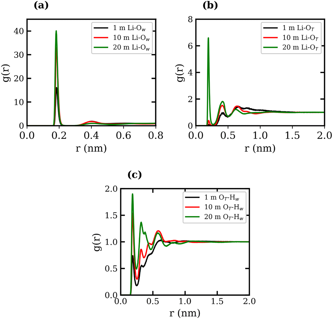 | ||
| Fig. 1 Radial distribution functions of (a) Li+ with O (water), (b) Li+ with O (TFSI−), and (c) O (TFSI−) with H (water), all shown for the 1 molal LiCl aqueous system (black), the 10 molal system (red) and the 20 molal system (green). | ||
| Conc., molal | Li-TFSI CN (1) | Li-TFSI CN (2) | Li–H2O CN |
|---|---|---|---|
| 1 | 0.139 ± 0.006 | 0.001 ± 0.001 | 3.996 ± 0.002 |
| 10 | 1.095 ± 0.001 | 0.021 ± 0.002 | 3.909 ± 0.002 |
| 20 | 2.134 ± 0.003 | 0.271 ± 0.001 | 2.865 ± 0.008 |
3.2 Liquid–vapour interfacial properties
We now proceed to analyse the interfacial properties of these electrolytes starting with the interfacial tension, γ, which can be computed from simulations using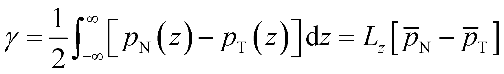 | (1) |
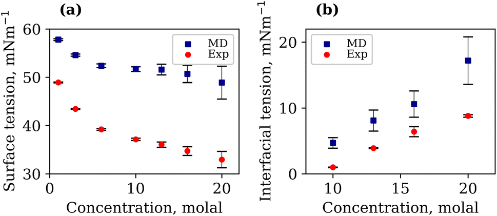
It is important to note that the TIP4P/2005 water model is known to underestimate the liquid–vapour surface tension, γLV, of pure water compared to experimental values.48 At 294.15 K, our calculated γLV for pure water was 64.97 mN m−1. This value is in agreement with that of Vega et al.,48 but lower than the experimental value of 71.99 mN m−1. The γLV values of aqueous LiCl at several molal concentrations using the Madrid-2019 force field were recently reported.49 Our results confirm the expected increase in γLV with LiCl concentration, as presented in Fig. S3 of the ESI.† The calculated and experimentally measured γLV values for 1, 3, 6, 10, 13, 16 and 20 molal aqueous LiTFSI systems are presented in Fig. 2(a). Both experimental findings and simulations demonstrate that the liquid–vapour surface tension decreases as the concentration of LiTFSI increases, indicating that LiTFSI exhibits surfactant-like behaviour. However, the calculated surface tension values are up to 49% larger than experimental measurements, giving worse predictions in the WiS regime (10–20 molal). This overestimation of surface tension has also been observed for other surfactant-like molecules when modelled using scaled-charge force fields.50 Despite the discrepancy in absolute values, the simulations correctly capture the trend observed experimentally. Above a concentration of 6 molal, the rate of decrease in surface tension slows, which may be indicative of the surface becoming saturated with TFSI− anions.
 | ||
| Fig. 2 Calculated (blue) and experimentally measured (red) interfacial tensions with respective errors in mN m−1, for (a) LiTFSI–vapour systems of 1, 3, 6, 10, 13, 16 and 20 molal, and (b) LiTFSI–LiCl systems of 10, 13, 16 and 20 molal (both phases). Errors are calculated based on block averages over 5 blocks using the full-precision averages. | ||
To better understand the observed decrease in surface tension with increasing LiTFSI concentration, the average number of water–water hydrogen bonds per water molecule, 〈nHB〉, was calculated as a function of the distance from the interface (i.e. along the z-axis). Hydrogen bonds were defined based on geometric criteria: molecules were considered hydrogen-bonded if the donor–acceptor distance was within 0.3 nm, and the donor–hydrogen–acceptor angle was less than or equal to 30°. The results are presented in Fig. 3(a) and (c). In agreement with previous studies,39,51 we find that as the salt concentration increases, the value of 〈nHB〉 decreases from approximately 3.7 hydrogen bonds per molecule in the 1 molal system to 0.5 hydrogen bonds per molecule in the 20 molal system. As expected, the number of hydrogen bonds between water molecules in the interfacial region is lower than that in the bulk for all systems. The value of 〈nHB〉 in the interfacial region also decreases with increasing salt concentration. Thus, the presence of TFSI− anions at the interface reduces the liquid–vapour surface tension in a similar manner to surfactants: aggregation of the amphiphilic molecule induces a reorganisation of water molecules at the interface, thereby disrupting the hydrogen-bond network of water at the surface and weakening the cohesive forces between water molecules.
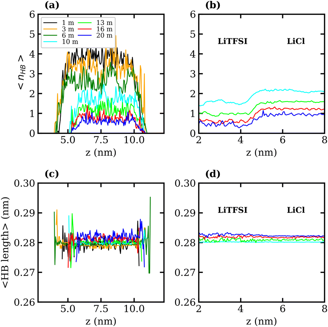 | ||
| Fig. 3 Number of water–water hydrogen bonds per water molecule, 〈nHB〉, as a function of z-position for the (a) LiTFSI–vapour and (b) LiTFSI–LiCl biphasic systems of 1 (black), 3 (orange), 6 (green), 10 (cyan), 13 (lime), 16 (red) and 20 (blue) molal. The corresponding average water–water hydrogen-bond length as a function of z-position for the (c) LiTFSI–vapour and (d) LiTFSI–LiCl biphasic systems. In the biphasic system, the LiTFSI phase is on the left, and the LiCl phase is on the right. | ||
Density profiles of aqueous LiTFSI–vapour systems were calculated to investigate the interfacial liquid structure as a function of LiTFSI concentration. Equilibrium density profiles of each system were computed over the final 60 ns of each trajectory. The density, ρ(z), of each species was normalised with respect to the corresponding bulk density, ρ0. Fig. 4(a)–(c) present the normalised density profiles for the 1, 10 and 20 molal concentrations, respectively, with profiles of the entire liquid–vapour box on the left, and of only the interfacial region on the right. Densities of the TFSI− anions' constituent atoms are presented to give an indication of atom ordering close to the interface. All systems show that TFSI− molecules preferentially adsorb at the liquid–vapour interface. The 1 molal system presents a significant peak in TFSI− density at the interface compared to the bulk. A peak in Li+ density occurs just below the interface, where there is a depletion region of TFSI−, indicating an electrical double-layer structure. Adsorption of TFSI− anions at the interface is also observed in the 10 and 20 molal systems. However, the degree of TFSI− enhancement at the interface, compared to the bulk density, is significantly higher in the 1 molal system (approximately 3.5× the bulk density) than in the WiS regime (approximately 1.25× the bulk density in the 10 and 20 molal systems). Thus, as the LiTFSI solutions become more saturated, the difference in TFSI− density between the interface and bulk becomes less pronounced. Nevertheless, the total density of TFSI− ions at the interface increases with salt concentration, which is reflected in Fig. S4,† and is consistent with the decrease in surface tension.
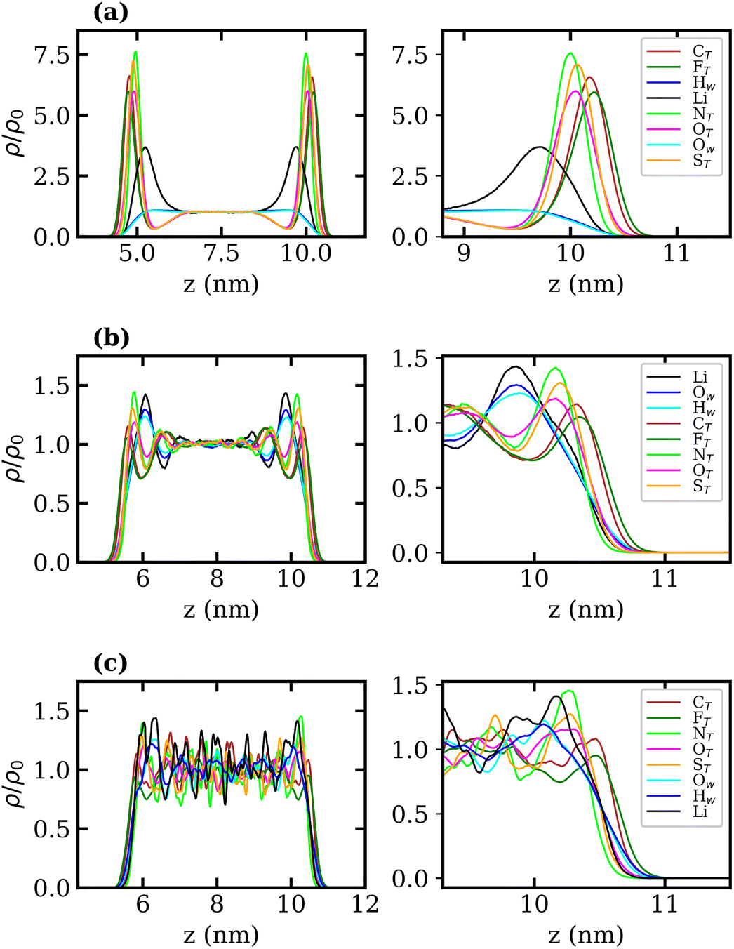 | ||
| Fig. 4 Normalised density profiles of Li+, each atom in TFSI− and water oxygen and hydrogen atoms in (a) 1, (b) 10 and (c) 20 molal aqueous LiTFSI as a function of depth in the z-direction (perpendicular to the plane of the liquid–vapour interface) in nm. Whole profiles are depicted on the left, while interfacial regions are depicted on the right. The density profile of each species has been calculated as a function of z-position, ρ, and divided by the corresponding bulk density, ρ0. | ||
A clear ordering preference of atoms in the TFSI− at the interface is also observed. Specifically, F atoms, followed by C atoms, gather closest to the interface, with N, O and S atoms appearing slightly further into the bulk. The C and F atoms of the TFSI−, which point towards the vapour phase, carry relatively small charges compared to the other atoms and constitute the hydrophobic part of the molecule. Conversely, N, O and S atoms that point towards the bulk are hydrophilic, carrying larger partial charges (as seen in the force-field parameters in Table S1†). The 10 and 20 molal systems also show an enhancement of Li+ just below the interface. In contrast to the 1 molal system, the WiS systems exhibit a peak in water density at the same location as the Li+ peak. Since there are far fewer water molecules in the WiS regime, a greater proportion of the system's water participates in ion solvation compared to the “free” bulk water seen in the more dilute systems. Hence, where there is an enhancement in the concentration of Li+ ions, there is also an enhanced concentration of solvating water molecules. This further supports the observation that a hydrophobic region exists near the interface, containing predominantly CF3 groups. Conversely, the OS–N–SO groups interact with Li+ ions and water molecules in a hydrophilic region situated just below the interface. Previous studies of ionic-liquid mixtures containing TFSI− anions have also reported an orientation preference with the CF3 groups pointing towards a vacuum interface,52,53 but this has not been confirmed for TFSI− in aqueous solutions. The hydrophobicity of perfluorinated hydrocarbon groups and their tendency to align close to liquid–vapour interfaces is also well-documented for surfactants in the literature.54–56
To determine whether the preferential interfacial adsorption of the CF3 groups induces a reorientation of the interfacial TFSI− anions, the angle, θ, between the vector connecting the two S atoms and the interface normal (see Fig. 5(a)) was calculated for all anions in the simulation box over the final 120 ns of each trajectory. The orientational order parameter, represented by the averaged second Legendre polynomial, 〈P2(cos![[thin space (1/6-em)]](https://www.rsc.org/images/entities/char_2009.gif) θ)〉 = 〈1/2(3cos2θ − 1)〉, was then calculated as a function of the distance from the interface. Fig. 5(b)–(d) present the variation of 〈P2(cosθ)〉 with respect to the z-coordinate for the 1, 10 and 20 molal systems, respectively. The plots indicate that the orientation of TFSI− in the bulk is random, as 〈P2(cosθ)〉 fluctuates around 0. Notably, in the bulk region of the 20 molal system, there are larger fluctuations around 0 compared to the less concentrated systems, which may indicate anion clustering. Approaching the interface, the value of 〈P2(cosθ)〉 decreases in all systems, reaching between −0.4 and −0.5 for the outermost molecules, indicating that interfacial TFSI− residues in the liquid–vapour systems adopt a parallel orientation with respect to the interface. This parallel orientation allows both CF3 groups to be positioned close to the vapour phase, occupying the outer layer of the surface, while the OS–N–SO groups reside further into the bulk. The value of 〈P2(cosθ)〉 begins to decrease at approximately 1.1 nm from the interface(s) in the 1 molal system, 0.95 nm in the 10 molal system, and 0.82 nm in the 20 molal system. Hence, interface-induced orientational structuring extends deeper into the bulk in the more dilute systems.
θ)〉 = 〈1/2(3cos2θ − 1)〉, was then calculated as a function of the distance from the interface. Fig. 5(b)–(d) present the variation of 〈P2(cosθ)〉 with respect to the z-coordinate for the 1, 10 and 20 molal systems, respectively. The plots indicate that the orientation of TFSI− in the bulk is random, as 〈P2(cosθ)〉 fluctuates around 0. Notably, in the bulk region of the 20 molal system, there are larger fluctuations around 0 compared to the less concentrated systems, which may indicate anion clustering. Approaching the interface, the value of 〈P2(cosθ)〉 decreases in all systems, reaching between −0.4 and −0.5 for the outermost molecules, indicating that interfacial TFSI− residues in the liquid–vapour systems adopt a parallel orientation with respect to the interface. This parallel orientation allows both CF3 groups to be positioned close to the vapour phase, occupying the outer layer of the surface, while the OS–N–SO groups reside further into the bulk. The value of 〈P2(cosθ)〉 begins to decrease at approximately 1.1 nm from the interface(s) in the 1 molal system, 0.95 nm in the 10 molal system, and 0.82 nm in the 20 molal system. Hence, interface-induced orientational structuring extends deeper into the bulk in the more dilute systems.
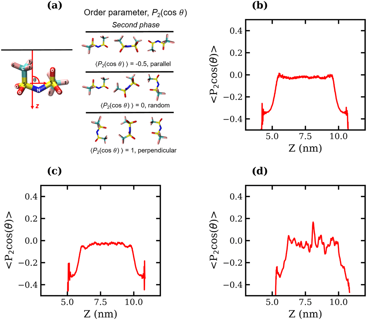 | ||
| Fig. 5 Average order parameter, 〈P2(cosθ)〉, of TFSI− anions measured as the second Legendre polynomial of θ, the angle between the S–S vector and interface normal (a), plotted against the Z coordinate for the (b) 1 molal, (c) 10 molal and (d) 20 molal liquid–vapour systems. | ||
From the density profiles, it is possible to extract the thickness of the interface by fitting to a hyperbolic tangent function of the form,
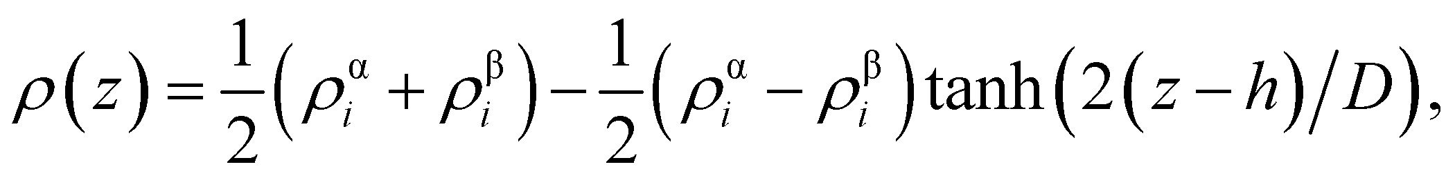 | (2) |
| Concentration, molal | Interfacial thickness, nm | |
|---|---|---|
| LV systems | LL systems | |
| 1 | 0.101 | |
| 3 | 0.177 | |
| 6 | 0.233 | |
| 10 | 0.302 | 0.904 |
| 13 | 0.323 | 0.828 |
| 16 | 0.360 | 0.821 |
| 20 | 0.324 | 0.606 |
3.3 Liquid–liquid interfacial properties
The interfacial molecular structure of aqueous biphasic WiS LiCl–LiTFSI systems remains largely unexplored. Such systems can be difficult to simulate due to their long relaxation times and high viscosities. Furthermore, it is crucial that a box of sufficient size is used to accurately describe the system's bulk and interfacial properties. MD simulations were performed on several systems containing equal (molal) concentrations of aqueous LiCl and LiTFSI in a parallelepiped simulation cell. The simulations correctly predicted the experimentally observed phase separation of LiCl and LiTFSI for all concentrations between 10 molal and 20 molal. Calculated interfacial tensions for biphasic systems of concentrations 10, 13, 16 and 20 molal, as shown in Fig. 2(b), are compared with corresponding experimentally measured values. Both simulation and experimental data indicate that the interfacial tension between LiCl and LiTFSI phases increases with increasing electrolyte concentration, suggesting the formation of a more stable interface between the liquids. The calculated interfacial tension values are systematically higher than the experimentally measured values for all concentrations, although the overall trend is the same in both cases.The average number of water–water hydrogen bonds per water molecule, 〈nHB〉, was calculated as a function of z-position in each biphasic system and is illustrated in Fig. 3(b). As observed in the LiTFSI (aq)–vapour systems, 〈nHB〉 throughout the system decreases as the salt concentration is increased. The average hydrogen-bond length increases with increasing salt concentration, as seen in Fig. 3(d).58 We also note the presence of distinct water environments in the LiCl and LiTFSI phases: water molecules in the LiTFSI phase form fewer hydrogen bonds compared to those in the LiCl phase.
Normalised density profiles were calculated for the 10 molal and 20 molal systems and are presented in Fig. 6(a) and (b), respectively. For Li+ ions and water, which are present in both phases, the density profiles have been normalised by the bulk density of species in the LiCl phase. Fig. 6(a) and (b) show a sharp interface between the two coexisting liquid phases. Both systems show that no TFSI− ions penetrate into the LiCl phase, while a small but significant number of Cl− ions are present in the LiTFSI phase in the 10 molal system. In the 20 molal system, however, there are very few Cl− ions present in the LiTFSI phase.
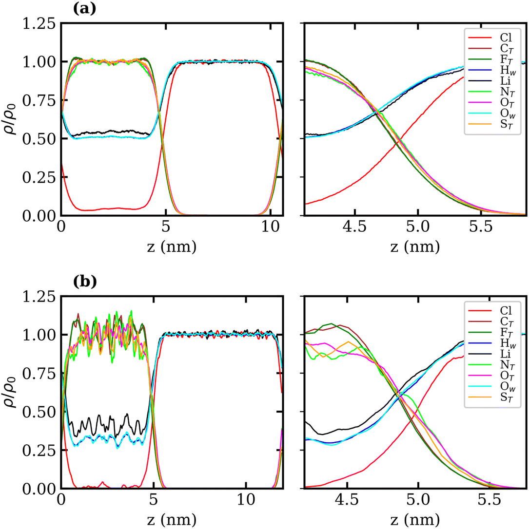 | ||
| Fig. 6 Bulk normalised atom-wise density profiles, ρ/ρ0, of Li+, Cl−, TFSI− and water in (a) the 10 molal and (b) the 20 molal aqueous LiCl–LiTFSI biphasic systems as a function of z-position (perpendicular to the plane of the liquid–vapour interface) in nm. The whole profile is depicted on the left, and the interfacial region is depicted on the right. For Li+, Ow and Hw, which are present in both phases, the density is divided by the corresponding bulk density in the LiCl phase. | ||
Much like the liquid–vapour systems, the normalised density profiles of the constituent atoms of TFSI− show significantly more fluctuations in the bulk of the 20 molal than in the 10 molal system. This implies the presence of regions of both higher and lower density of TFSI− anions, which could be indicative of TFSI− clustering in the WiS regime.17 Compared to the WiS LiTFSI–vapour systems (Fig. 4(b) and (c)), the ordering of TFSI− atoms close to the interface in the biphasic systems is far less distinguishable. In the 10 molal system, we observe a slight ordering preference, with NTFSI, OTFSI, and STFSI being closest to the liquid–liquid interface, while CTFSI and FTFSI reside slightly deeper in the bulk phase. The 20 molal solutions present the same ordering preference close to the interface. Interestingly, this is the opposite ordering preference to that observed in the LiTFSI–vapour interfaces, where the CF3 groups point towards the vapour phase. The presence of water and Li+ ions across the interface creates a more hydrophilic interfacial region, which induces a different adsorption preference in the TFSI−, with the hydrophilic moiety (OS–N–SO) pointing towards the interface. The CF3 group, being more hydrophobic, is strongly repelled by the hydrophilic LiCl phase and hence is pushed inward towards the bulk.
The orientation of TFSI− anions was also examined in liquid–liquid biphasic systems. The results are presented in Fig. 7. Unlike what was observed for the liquid–vapour interface, in this case, the interfacial anions do not exhibit a strong preference in orientation, as evidenced by the fluctuation of 〈P2(cosθ)〉 around 0 at all values of z. The 20 molal ABS shows much greater fluctuation around 0 than the 10 molal system, which may suggest some degree of structuring in the liquid.
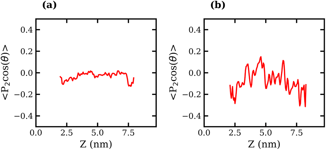 | ||
| Fig. 7 Average order parameter, 〈P2(cosθ)〉, of TFSI− anions measured as the second Legendre polynomial of θ, the angle between the S–S vector and interface normal, plotted against the Z coordinate for the (a) 10 molal and (b) 20 molal liquid–liquid systems. | ||
The “90–10” interfacial thicknesses of the 10, 13, 16 and 20 molal ABSs are presented in Table 2. The interfacial thickness decreases with increasing concentration of both LiCl and LiTFSI. This decrease indicates the formation of a more stable interface between the two phases as the salt concentration is increased, which is in agreement with the increasing surface tension. The surface excess of TFSI− with respect to the Gibbs dividing surface of water was also calculated. Negative surface excess values were observed for all concentrations, indicating a depletion of TFSI− at the interface when compared with water, as seen in Table S5 of the ESI.† Again, despite the large fluctuations in the density profiles mainly for the WiS regime solutions, a trend can be observed in the data indicating that as concentration increases, the degree of TFSI− depletion from the interface reduces.
With the surface tension and bulk solution densities measured, we can apply capillary wave theory59,60 to derive an alternative measure of the interfacial thickness, by first calculating the capillary length, a, as
| a2 = 2γ/(g(ρ1 − ρ2)), | (3) |
 | (4) |
| Concentration, molal | Interfacial thickness, nm | |||
|---|---|---|---|---|
| LV systems | LL systems | |||
| MD | Exp | MD | Exp | |
| 1 | 0.479 | 0.519 | — | — |
| 3 | 0.488 | 0.546 | — | — |
| 6 | 0.496 | 0.571 | — | — |
| 10 | 0.498 | 0.585 | 1.600 | 3.418 |
| 13 | 0.498 | 0.593 | 1.227 | 1.754 |
| 16 | 0.502 | 0.604 | 1.078 | 1.378 |
| 20 | 0.511 | 0.620 | 0.851 | 1.180 |
To understand the physical interactions driving liquid–liquid phase separation, we used MD simulations to calculate the energetic contributions to the system's total energy as a function of electrolyte concentration(s). Among the various contributions, the one that varies the most is the Coulomb energy (calculated with a cut-off of 1.2 nm) reported in Fig. 8. The results show that increasing salt concentration increases the Coulomb interaction strength between Li+ and Cl− ions significantly, consistent with the enhanced Li–Cl contact ion pairing. The strength of Li–water (orange) and Cl–water (blue) Coulomb interactions also increases with salt concentration, while TFSI–water interactions (red) remain relatively unchanged. These observations may suggest a ‘salting out’ effect, where stronger Li–Cl, Li–water and Cl–water interactions compete with TFSI–water interactions, leading to the exclusion of TFSI from the LiCl phase and subsequent phase separation. While a detailed exploration of the free-energy landscape is necessary for definitive conclusions on the origin of phase separation, the experimental data presented herein supports our observations. The bubble plot displayed in Fig. 9 presents the experimental interfacial tension between liquid phases in a biphasic system, where circle size is linearly proportional to the interfacial tension. The y-axis represents the molal concentration of LiCl, and the x-axis represents the molal concentration of LiTFSI. The interfacial tension shows a more significant increase with increasing LiCl concentration as compared to equivalent increases in LiTFSI concentration. This implies that the concentration of LiCl has a greater effect on interfacial tension and, thus, phase separation than the concentration of LiTFSI. The values of the experimental interfacial tension of asymmetric systems are presented in Table S6 of the ESI.†
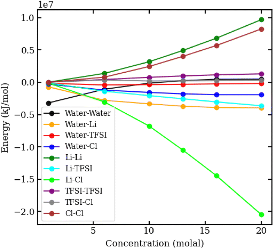 | ||
| Fig. 8 Coulomb interaction energies in kJ mol−1 between pairs of species in aqueous LiCl–LiTFSI biphasic systems, plotted against molal concentration. | ||
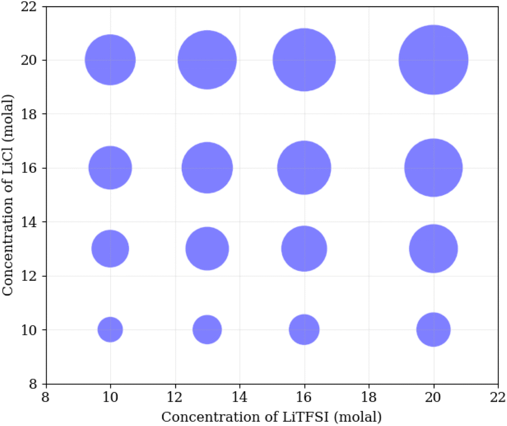 | ||
| Fig. 9 Bubble plot, where the size of circles is linearly proportional to the experimental interfacial tension between liquid phases in a biphasic system, with molal concentration of LiCl on the y-axis, and molal concentration of LiTFSI on the x-axis. | ||
Finally, the transport of Li+ ions across the interface was investigated for the 10 and 20 molal ABSs. The results are presented in Fig. 10, where the percentage of Li+ ions that migrate from one phase to the other is plotted against the average distance these ions travel into the second phase, calculated as the distance, in the z-direction, from the Gibbs dividing surface. Alongside the increase in interfacial tension and the decrease in interfacial thickness, both suggesting the formation of a more stable liquid–liquid interface, the increase in concentration of both salts leads to a reduction in diffusion of Li+ ions between the phases. The migration of Li+ ions between phases is minimal, with far less than 1% of Li+ ions from the LiCl phase observed to move into the LiTFSI phase, and less than 0.01% of Li+ ions moving from the LiTFSI phase to the LiCl phase. The increased migration of Li+ from the LiCl phase to the LiTFSI phase in the 10 molal system may be due to the small but significant number of Cl− ions that travel into the LiTFSI phase during the simulation, as seen in the density profile (Fig. 6(a)). The sequence of ion penetration – whether Li+ or Cl− ions migrate first – cannot be discerned from our current results. In the 10 molal system, the increased transport of Li+ ions could be attributed to the lower density of the phases, but it is also plausible that the presence of Cl− ions in the LiTFSI phase contributes to this enhanced transport, although the causative relationship between the two observations remains to be determined. We do however, note that the charge density profile, presented in Fig. S5 of the ESI,† shows that the two phases are neutral, indicating that the transfer of anions and cations from the LiCl phase to the LiTFSI phase is balanced. Comparatively, far fewer Li+ ions migrate into the LiTFSI phase in the 20 molal system, which may be due to the fact there are very few/no Cl− ions present in the LiTFSI phase at this concentration. Specifically, in the 20 molal system, Li+ ions do not penetrate beyond 0.4 nm from the interface, while in the 10 molal system, Li+ ions penetrate up to 3.7 nm into the LiTFSI phase.
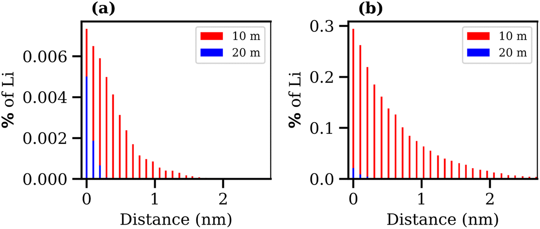 | ||
| Fig. 10 Bar charts presenting the distance travelled by Li+ ions that migrate from (a) the LiTFSI phase to the LiCl phase, for the 10 molal biphasic system (red) and 20 molal biphasic system (blue) and (b) the LiCl phase into the LiTFSI phase over the final 10 ns of the trajectory. The y-axis shows the percentage of Li+ ions that move relative to the total number of Li+ ions in the phase they move from. The x-axis represents the z-depth of penetration that those Li+ move into the second phase, measured from the Gibbs dividing surface. | ||
4 Summary and conclusions
In this study, we employed newly developed scaled-charge force-field models in molecular dynamics simulations to investigate the structural and interfacial properties of dilute and WiS solutions containing LiTFSI and LiCl aqueous electrolytes. Structural analysis of our simulations revealed the striking differences between the liquid–vapour and liquid–liquid interfacial structure. We show that in the former, the TFSI− ions behave like a surfactant, reducing the surface tension as the concentration of the electrolyte increases, due to a disruption of the interfacial water hydrogen-bonding network. These ions preferentially adsorb at the interface, positioning their hydrophobic CF3 groups toward the vapour phase and their polar, hydrophilic OS–N–SO groups inward toward the bulk. This results in an excess negative charge region, which induces a double-layer effect of enhanced Li+ just below the interface. Additionally, the hydrophobic moieties' adsorption at the interface induces a parallel orientation preference for TFSI− anions (relative to the plane of the interface). Notably, this surfactant-like behaviour has not been previously reported, and indicates that the amphiphilic nature of the TFSI− is a crucial part of the liquid structure.In contrast, the surface tension of the liquid–liquid systems increases with increasing concentration in both phases, with the interface becoming thinner and sharper, indicative of an increase in interfacial stability. The TFSI− anions close to the interface in the 20 molal system have a slight preference to align with their polar OS–N–SO groups pointing towards the interface, and their non-polar CF3 groups pointing towards the bulk. The respective phases contain distinct water–water hydrogen bonding environments, with fewer, shorter hydrogen bonds in the LiTFSI phase compared with the LiCl phase. Density profiles revealed several interesting structural features. The LiCl phase contains no TFSI− anions, while the LiTFSI phase contains several Cl− anions. This small charge imbalance might be the driving force behind the Li+ diffusion across the liquid–liquid interface, which is greater at concentrations where this imbalance is higher.
Finally, the calculation of pairwise coulombic energies suggests that the liquid–liquid phase separation is the result of a ‘salting out’ effect, causing TFSI exclusion from the LiCl phase as the concentration of salt is increased. Experimental data further corroborate these findings, showing that LiCl concentration more significantly affects interfacial tension and thus phase separation than LiTFSI concentration.
Author contributions
Hannah O. Wood: methodology (computational part), investigation (computational part), formal analysis (computational part), writing – original draft preparation. Hannah M. Burnett: methodology (experimental part), investigation (experimental part), formal analysis (experimental part). Robert A. W. Dryfe: conceptualization, methodology, supervision. Paola Carbone: conceptualization, methodology, writing – reviewing, supervision.Conflicts of interest
There are no conflicts to declare.Acknowledgements
This work was supported by the EPSRC CDT Graphene NOWNANO, grant EP/L01548X/1. The EPSRC are thanked for financial support via grant EP/T01816X/1. Simulations were performed on the computational shared facility (CSF) at the University of Manchester.Notes and references
- H. Zhang, X. Ji, P. Li, C. Liu, J. Lou, Z. Wang, W. Wen, Y. Xiao, M. Zhang and X. Zhu, Sci. China: Life Sci., 2020, 63, 953–985 CrossRef PubMed.
- K. A. Kurnia, M. G. Freire and J. A. Coutinho, J. Phys. Chem. B, 2014, 118, 297–308 CrossRef CAS PubMed.
- R. Hatti-Kaul, Aqueous Two-Phase Systems: Methods and Protocols, Springer Science & Business Media, 2008, vol. 11 Search PubMed.
- N. J. Bridges, K. E. Gutowski and R. D. Rogers, Green Chem., 2007, 9, 177–183 RSC.
- N. Dubouis, C. Park, M. Deschamps, S. Abdelghani-Idrissi, M. Kanduc, A. Colin, M. Salanne, J. Dzubiella, A. Grimaud and B. Rotenberg, ACS Cent. Sci., 2019, 5, 640–643 CrossRef CAS PubMed.
- M. Marchel, J. Niewisiewicz, A. S. Coroadinha and I. M. Marrucho, Sep. Purif. Technol., 2020, 252, 117480 CrossRef CAS.
- C. Yang, L. Suo, O. Borodin, F. Wang, W. Sun, T. Gao, X. Fan, S. Hou, Z. Ma and K. Amine, et al. , Proc. Natl. Acad. Sci. U. S. A., 2017, 114, 6197–6202 CrossRef CAS PubMed.
- C. Yang, J. Chen, X. Ji, T. P. Pollard, X. Lü, C.-J. Sun, S. Hou, Q. Liu, C. Liu and T. Qing, et al. , Nature, 2019, 569, 245–250 CrossRef CAS PubMed.
- A. Serva, N. Dubouis, A. Grimaud and M. Salanne, Acc. Chem. Res., 2021, 54, 1034–1042 CrossRef CAS PubMed.
- P. Navalpotro, C. M. Neves, J. Palma, M. G. Freire, J. A. Coutinho and R. Marcilla, Advanced Science, 2018, 5, 1800576 CrossRef PubMed.
- P. Navalpotro, N. Sierra, C. Trujillo, I. Montes, J. Palma and R. Marcilla, ACS Appl. Mater. Interfaces, 2018, 10, 41246–41256 CrossRef CAS PubMed.
- P. Navalpotro, C. Trujillo, I. Montes, C. M. Neves, J. Palma, M. G. Freire, J. A. Coutinho and R. Marcilla, Energy Storage Mater., 2020, 26, 400–407 CrossRef.
- H. Ahn, D. Kim, M. Lee and K. W. Nam, Commun. Mater., 2023, 4, 37 CrossRef.
- L. Suo, O. Borodin, T. Gao, M. Olguin, J. Ho, X. Fan, C. Luo, C. Wang and K. Xu, Science, 2015, 350, 938–943 CrossRef CAS PubMed.
- Z. Peng, X. Cao, P. Gao, H. Jia, X. Ren, S. Roy, Z. Li, Y. Zhu, W. Xie and D. Liu, et al. , Adv. Funct. Mater., 2020, 30, 2001285 CrossRef CAS.
- W. Wang, J. Zhang, Q. Yang, S. Wang, W. Wang and B. Li, ACS Appl. Mater. Interfaces, 2020, 12, 22901–22909 CrossRef CAS PubMed.
- O. Borodin, L. Suo, M. Gobet, X. Ren, F. Wang, A. Faraone, J. Peng, M. Olguin, M. Schroeder and M. S. Ding, et al. , ACS Nano, 2017, 11, 10462–10471 CrossRef CAS PubMed.
- O. Borodin, J. Self, K. A. Persson, C. Wang and K. Xu, Joule, 2020, 4, 69–100 CrossRef CAS.
- M. Chen, G. Feng and R. Qiao, Curr. Opin. Colloid Interface Sci., 2020, 47, 99–110 CrossRef CAS.
- N. Dubouis, P. Lemaire, B. Mirvaux, E. Salager, M. Deschamps and A. Grimaud, Energy Environ. Sci., 2018, 11, 3491–3499 RSC.
- L. Suo, D. Oh, Y. Lin, Z. Zhuo, O. Borodin, T. Gao, F. Wang, A. Kushima, Z. Wang and H.-C. Kim, et al. , J. Am. Chem. Soc., 2017, 139, 18670–18680 CrossRef CAS PubMed.
- J. Vatamanu and O. Borodin, J. Phys. Chem. Lett., 2017, 8, 4362–4367 CrossRef CAS PubMed.
- A. Triolo, V. Di Lisio, F. Lo Celso, G. B. Appetecchi, B. Fazio, P. Chater, A. Martinelli, F. Sciubba and O. Russina, J. Phys. Chem. B, 2021, 125, 12500–12517 CrossRef CAS PubMed.
- P. Kumari, V. Pillai, D. Gobbo, P. Ballone and A. Benedetto, Phys. Chem. Chem. Phys., 2021, 23, 944–959 RSC.
- T. Mendez-Morales, Z. Li and M. Salanne, Batteries Supercaps, 2021, 4, 646–652 CrossRef CAS.
- X. Liu, S.-C. Lee, S. Seifer, R. E. Winans, L. Cheng and T. Li, et al. , Energy Storage Mater., 2022, 45, 696–703 CrossRef.
- X. Liu, Z. Yu, E. Sarnello, K. Qian, S. Seifert, R. E. Winans, L. Cheng and T. Li, Energy Mater. Adv., 2021, 2021, 7368420 Search PubMed.
- J. Lim, K. Park, H. Lee, J. Kim, K. Kwak and M. Cho, J. Am. Chem. Soc., 2018, 140, 15661–15667 CrossRef CAS PubMed.
- K. S. Han, Z. Yu, H. Wang, P. C. Redfern, L. Ma, L. Cheng, Y. Chen, J. Z. Hu, L. A. Curtiss and K. Xu, et al. , J. Phys. Chem. B, 2020, 124, 5284–5291 CrossRef CAS PubMed.
- G. Horwitz, E. Hark, P. Y. Steinberg, L. P. Cavalcanti, S. Risse and H. R. Corti, ACS Nano, 2021, 15, 11564–11572 CrossRef CAS PubMed.
- M. A. Gonzalez, O. Borodin, M. Kofu, K. Shibata, T. Yamada, O. Yamamuro, K. Xu, D. L. Price and M.-L. Saboungi, J. Phys. Chem. Lett., 2020, 11, 7279–7284 CrossRef CAS PubMed.
- N. H. Lewis, Y. Zhang, B. Dereka, E. V. Carino, E. J. Maginn and A. Tokmakoff, J. Phys. Chem. C, 2020, 124, 3470–3481 CrossRef CAS.
- N. Dubouis, A. France-Lanord, A. Brige, M. Salanne and A. Grimaud, J. Phys. Chem. B, 2021, 125, 5365–5372 CrossRef CAS PubMed.
- A. A. Chialvo and O. D. Crisalle, J. Phys. Chem. B, 2021, 125, 12028–12041 CrossRef CAS PubMed.
- D. Van Der Spoel, E. Lindahl, B. Hess, G. Groenhof, A. E. Mark and H. J. Berendsen, J. Comput. Chem., 2005, 26, 1701–1718 CrossRef CAS PubMed.
- L. Verlet, Phys. Rev., 1967, 159, 98 CrossRef CAS.
- I. Zeron, J. Abascal and C. Vega, J. Chem. Phys., 2019, 151, 134504 CrossRef CAS PubMed.
- J. L. Abascal and C. Vega, J. Chem. Phys., 2005, 123, 234505 CrossRef CAS PubMed.
- Y. Zhang, N. H. Lewis, J. Mars, G. Wan, N. J. Weadock, C. J. Takacs, M. R. Lukatskaya, H.-G. Steinruck, M. F. Toney and A. Tokmakoff, et al. , J. Phys. Chem. B, 2021, 125, 4501–4513 CrossRef CAS PubMed.
- J. Wang, R. M. Wolf, J. W. Caldwell, P. A. Kollman and D. A. Case, J. Comput. Chem., 2004, 25, 1157–1174 CrossRef CAS PubMed.
- L. Martínez, R. Andrade, E. G. Birgin and J. M. Martínez, J. Comput. Chem., 2009, 30, 2157–2164 CrossRef PubMed.
- E. A. Muller, Å. Ervik and A. Mejía, Living J. Comp. Mol. Sci., 2020, 2, 21385 Search PubMed.
- A. Yllö and C. Zhang, Chem. Phys. Lett., 2019, 729, 6–10 CrossRef.
- S. Varma and S. B. Rempe, Biophys. Chem., 2006, 124, 192–199 CrossRef CAS PubMed.
- Y. Marcus, Chem. Rev., 1988, 88, 1475–1498 CrossRef CAS.
- J. Jeon, H. Lee, J.-H. Choi and M. Cho, J. Phys. Chem. C, 2020, 124, 11790–11799 CrossRef CAS.
- H. S. Dhattarwal and H. K. Kashyap, J. Phys. Chem. B, 2022, 126, 5291–5304 CrossRef CAS PubMed.
- C. Vega and E. de Miguel, J. Chem. Phys., 2007, 126, 154707 CrossRef CAS PubMed.
- S. Blazquez, M. Conde and C. Vega, J. Chem. Phys., 2023, 158, 054505 CrossRef CAS PubMed.
- M. J. Servis, A. McCue, A. J. Casella and A. E. Clark, Fluid Phase Equilib., 2020, 511, 112497 CrossRef CAS.
- S. Han, Sci. Rep., 2018, 8, 9347 CrossRef PubMed.
- K. Nakajima, A. Ohno, H. Hashimoto, M. Suzuki and K. Kimura, J. Chem. Phys., 2010, 133, 044702 CrossRef PubMed.
- Y. Zhang, Y. Khalifa, E. J. Maginn and J. T. Newberg, J. Phys. Chem. C, 2018, 122, 27392–27401 CrossRef CAS.
- V. H. Dalvi and P. J. Rossky, Proc. Natl. Acad. Sci. U. S. A., 2010, 107, 13603–13607 CrossRef CAS PubMed.
- L. Zhang, P. Wu, Q. Wei, J.-W. Shen, Z. Liu, T. Ren, W. Zhang and X. Wang, J. Mol. Liq., 2016, 222, 988–994 CrossRef CAS.
- A. Jackson, P. Li, C. Dong, R. Thomas and J. Penfold, Langmuir, 2009, 25, 3957–3965 CrossRef CAS PubMed.
- M. P. Allen and D. J. Tildesley, Computer Simulation of Liquids, Clarendon Press and Oxford University Press, Oxford, UK and New York, 1987 Search PubMed.
- E. Espinosa, E. Molins and C. Lecomte, Chem. Phys. Lett., 1998, 285, 170–173 CrossRef CAS.
- J. S. Rowlinson and B. Widom, Molecular Theory of Capillarity, Clarendon Press, Oxford, Oxfordshire, 1982 Search PubMed.
- F. Buff, R. Lovett and F. Stillinger Jr, Phys. Rev. Lett., 1965, 15, 621 CrossRef.
- D. Degoulange, R. Pandya, M. Deschamps, D. Skiba, B. Gallant, S. Gigan, H. de Aguiar and A. Grimaud, Proc. Natl. Acad. Sci. U. S. A., 2023, 120, e2220662120 CrossRef CAS PubMed.
Footnote |
| † Electronic supplementary information (ESI) available. See DOI: https://doi.org/10.1039/d4fd00026a |
| This journal is © The Royal Society of Chemistry 2024 |