Naked micelles: well-defined polymer nanoparticles from photo-cleavable block copolymer micelles†
Giada
Quintieri
and
André H.
Gröschel
 *
*
Physical Chemistry, University of Münster, Correns. 28–30, 48149 Münster and Center for Soft Nanoscience (SoN), University of Münster, Busso-Peus-Str. 10, 48149 Münster, Germany. E-mail: andre.groeschel@uni-muenster.de
First published on 18th November 2020
Abstract
Ultra-small nanoparticles (NPs) with accessible surface functionalities in the range of 3–50 nm are of great interest due to their defined size and surface properties, which could bridge the gap between natural and synthetic materials. Although NPs available in nature present more sophisticated functions as compared to synthetic materials, the physicochemical and colloidal behaviour is primarily dominated by geometry and surface charge; synthetic counterparts could mimic aggregation and interaction behaviour based on similar size, shape and surface structure. Inorganic ultra-small NPs exist in a large variety; however polymeric counterparts present major problems when trying to produce them in a controlled manner in the sub-50 nm range. Here, we present the synthesis and self-assembly of a photolabile diblock copolymers into spheres, worms and vesicles followed by photocleaving of the corona leaving the core unaltered, which is then surrounded by negative charge. The polymer features a water-soluble polyethylene oxide (PEO) corona block and a hydrophobic polystyrene (PS) core block. The two blocks are covalently linked by an o-nitrobenzyl moiety (ONB), which upon exposure to UV light (λ = 365 nm) opens up, leaving a carboxylic acid functionality on the PS core for electrostatic stabilization. The negatively charged core then interacts with cationic species, e.g., cationic gold NPs (AuNPs), which will decorate the PS surface.
Introduction
Nanoparticles with defined size and surface are found in many areas of nature, science, and technology. Probably most common are inorganic nanocrystals1 (e.g. gold) and biological NPs (e.g. virus) that both are often stabilized by electrostatic repulsion of surface charges. While inorganic NPs are formed via nucleation and growth stabilized by surfactants to control the interface and thereby size and shape, virus particles are self-assembled from highly-defined building blocks providing organic NPs with control of composition and charge distribution.2 For instance, the CCMV virus3 has a monodisperse hydrodynamic diameter of 28 nm and an icosahedral distribution of net negative surface charge. Since both inorganic and biological NPs are so well-controlled in size and directional interaction, their electrostatic attraction can be tuned precisely to self-assemble into NP crystals and co-crystals with highly ordered lattices.4–6Synthetic organic NPs with bare surface on the other hand are rather difficult to produce in similar size ranges (i.e., Dh = 10–30 nm). Crystals or co-crystals of polymer NPs with inorganic or biological NPs are therefore currently beyond our reach, despite the large toolbox of polymer-specific properties. Polymer particles with exceptional control over size dispersity are typically synthesized by emulsion polymerization or variations thereof, which gives access to nano- and microparticles larger than 100 nm. Most prominent are latex particles in the micrometre range able to crystallize due to very low deviation in particle diameter.7 They have raised considerable interest for applications8 and as model system to study crystallization phenomena on a size scale that is convenient for imaging.9 Reducing the target size to the sub-100 nm range results in higher particle dispersity due to difficulties in stabilizing the increasing surface energy. In order to go below the 50–100 nm range, microemulsion polymerization is a very promising approach as it already successfully demonstrated the synthesis of polymer NPs with Dh = 20–60 nm with similar surface chemistry as compared to the microscale analogues (yet, not entirely homogeneous).10 Microemulsions are thermodynamically stable emulsions with few nanometre-sized droplets at high volume fraction. During monomer polymerization – in a similar manner as for classical emulsion polymerization – shape and size-dispersity change because of droplet coalescence and thermal fluctuations. Although this technique is still one of the most promising approaches to address the sub-50 nm range, microemulsions are not accessible for every system and polymerization processes are complex.
With respect to polymer “NPs”, block copolymers are well-known to form narrowly size-dispersed nanostructures11 as well as solution morphologies by self-assembly including spherical micelles, cylindrical micelles, and vesicles.12 Polymerization-induced self-assembly (PISA) is another promising route for the scalable synthesis of polymer nanoparticles, where the morphology can be tuned during polymerization and chain extension of the solvophobic block.13,14 Micelles are generally stabilized by the surrounding brush-like corona that can take up a large volume fraction of the entire micelle. The corona also alters solution behaviour and interaction with other particles or interfaces. Regarding higher order self-assembly, spherical micelles demonstrate the ability to form soft colloidal crystals15 (even photonic)16 and quasicrystals with features specific to the soft micelle–micelle interaction.17 In order to investigate the self-assembly and co-assembly behaviour in a similar manner as compared to hard colloids (e.g. silica or latex particles),7 it would be desirable to generate polymer NPs with accessible surface and hard electrostatic interaction. Such NPs could be a valuable contribution to supracolloidal self-assembly of nanoscopic colloidal molecules, nanoparticle lattices, and organic–inorganic hybrids.18–21
We here report on the self-assembly of photocleavable poly(ethylene oxide)-orthonitrobenzyl-block-polystyrene (PEO-ONB-b-PS) BCPs into homogeneous micelles, which can be stripped of their corona by UV irradiation to form naked micelles. We synthetized different PS block length leading to spheres, worms and vesicles. Using a dedicated step-wise solution self-assembly route, we obtain homogeneous micelle populations. Once the BCPs or micelles are irradiated by UV light (λ = 365 nm), the photosensitive ONB linker cleaves between core and corona leaving a carboxylic acid functionality on the PS core, which remains unaltered in shape and size. We analysed the particle size and shape with TEM and DLS, and calculated the total acidic content with Zeta-sizer and titration. The created negative charge on the core provides electrostatic repulsion and introduces pH-responsiveness. We studied the effect of particle concentration and pH on particles stability and aggregation behaviour. The anionic surface could further be paired with cationic AuNPs, which bind to the PS core by electrostatic interaction.
Experimental
Materials
All chemicals were used as received, unless otherwise specified. Poly(ethylene glycol) monomethyl ether (Mn, PEG = 5000 g mol−1, Aldrich), 5-hydroxy-2-nitrobenzyl alcohol (>97%, Aldrich), K2CO3 (99%, Applichem), propargyl bromide (80% in toluene, Alfa Aesar), NaCl (≥99.5%, Roth), Na2SO4 (≥99%, Roth), sodium azide (≥99,5%, Aldrich), triethylamine (99%, Merck), p-toluenesulfonyl chloride (≥98%, Aldrich), CuBr (98%, Alfa Aesar), N,N,N′,N′′,N′′-pentamethyldiethylenetriamine (PMDETA, 99%, Aldrich), 4-(dimethylamino)pyridine (DMAP, >99%, Aldrich), 2-bromo-2-methylpropanoyl bromide (98%, Aldrich), octadecylamine (ODA, ≥99.0% (GC), Aldrich), (11-mercaptoundecyl)-N,N,N-trimethylammonium bromide (MUTAB, Aldrich) were used without further purification. Styrene (>99%, Merck) was passed over a silica column to remove the inhibitor prior to use. All solvents were of analytical (p.a.) or HPLC grade. The water used for the self-assembly processes was obtained from a water purification system (Merck) with a measured resistivity of 18.2 MΩ cm.Methods
![[thin space (1/6-em)]](https://www.rsc.org/images/entities/char_2009.gif) :
:![[thin space (1/6-em)]](https://www.rsc.org/images/entities/char_2009.gif) Hex = 1
Hex = 1![[thin space (1/6-em)]](https://www.rsc.org/images/entities/char_2009.gif) :
:![[thin space (1/6-em)]](https://www.rsc.org/images/entities/char_2009.gif) 2 as eluent. The mixture was cooled to room temperature and the product precipitated in 300 mL H2O. The solution was extracted using AcOEt (3 × 75 mL), the organic phase was washed with 1 M HCl (1 × 75 mL), and a sat. solution of NaCl (1 × 75 mL). The organic phases were combined, dried over Na2SO4, filtered and the solvent was removed in vacuo. The residue was purified by column chromatography using EtOAc
2 as eluent. The mixture was cooled to room temperature and the product precipitated in 300 mL H2O. The solution was extracted using AcOEt (3 × 75 mL), the organic phase was washed with 1 M HCl (1 × 75 mL), and a sat. solution of NaCl (1 × 75 mL). The organic phases were combined, dried over Na2SO4, filtered and the solvent was removed in vacuo. The residue was purified by column chromatography using EtOAc![[thin space (1/6-em)]](https://www.rsc.org/images/entities/char_2009.gif) :
:![[thin space (1/6-em)]](https://www.rsc.org/images/entities/char_2009.gif) Hex = 1
Hex = 1![[thin space (1/6-em)]](https://www.rsc.org/images/entities/char_2009.gif) :
:![[thin space (1/6-em)]](https://www.rsc.org/images/entities/char_2009.gif) 2 as eluent (2.69 g, Yield: 73%).
2 as eluent (2.69 g, Yield: 73%).
1H NMR (400 MHz, DMSO-d6) δ 8.16 (d, J = 9.1 Hz, 1H, Aromatic), 7.41 (dd, J = 2.5, 1.4 Hz, 1H, Aromatic), 7.09 (dd, J = 9.1, 2.9 Hz, 1H, Aromatic), 5.61 (t, J = 5.5 Hz, 1H, –OH), 4.98 (d, J = 2.4 Hz, 2H, –CH2–OH), 4.86 (d, J = 5.4 Hz, 2H, C![[triple bond, length as m-dash]](https://www.rsc.org/images/entities/char_e002.gif) C–CH2–), 3.67 (t, J = 2.4 Hz, 1H, C
C–CH2–), 3.67 (t, J = 2.4 Hz, 1H, C![[triple bond, length as m-dash]](https://www.rsc.org/images/entities/char_e002.gif) CH).
CH).
13C NMR (101 MHz, DMSO) δ 161.48, 142.24, 139.90, 127.37, 113.79, 113.13, 79.09, 78.36, 60.15, 56.14, 39.52.
ESI-MS: m/z = 230.04.
1H NMR (400 MHz, Chloroform-d) δ 7.33 (d, J = 8.0 Hz, 2H, Aromatic), 7.21 (d, J = 8.0 Hz, 2H, Aromatic), 3.63 (s, 450H, –CH2–CH2– (PEO)), 3.36 (s, 3H, CH3 (PEO)), 2.43 (s, 3H, CH3 Aromatic).
1H NMR (400 MHz, Chloroform-d) δ 3.63 (s, 450H –CH2–CH2– (PEO)), 3.37 (s, 3H, CH3 (PEO)).
1H NMR (400 MHz, Chloroform-d) δ 8.17 (t, J = 9.2 Hz, 1H, Aromatic), 7.94 (s, 1H, Triazole), 7.52–7.41 (m, 1H, Aromatic), 7.06–6.93 (m, 1H, Aromatic), 5.32 (s, 2H, CH2–O), 4.61–4.48 (m, 2H, CH2–OH), 3.63 (s, 450H), 3.37 (s, 3H, CH3–O (PEO)).
1H NMR (400 MHz, Chloroform-d) δ 8.20 (d, J = 9.1 Hz, 1H, Aromatic), 7.89 (s, 1H, Triazole), 7.29 (t, J = 3.6 Hz, 2H, Aromatic), 7.07 (dd, J = 9.2, 2.8 Hz, 1H, Aromatic), 5.65 (s, 2H, CH2–O), 5.30 (s, 2H, CH2–O–C![[double bond, length as m-dash]](https://www.rsc.org/images/entities/char_e001.gif) O), 3.63 (s, 450H, CH2–CH2 (PEO)), 3.37 (s, 3H, CH3–O (PEO)), 2.01 (s, 6H, CH3–C–CH3 (Br)).
O), 3.63 (s, 450H, CH2–CH2 (PEO)), 3.37 (s, 3H, CH3–O (PEO)), 2.01 (s, 6H, CH3–C–CH3 (Br)).
![[thin space (1/6-em)]](https://www.rsc.org/images/entities/char_2009.gif) 000 g mol−1. For each solvent, the dialysis bath was replaced 4 times at intervals of 4 h. The resulting micelle solution had a concentration of 1 mg mL−1.
000 g mol−1. For each solvent, the dialysis bath was replaced 4 times at intervals of 4 h. The resulting micelle solution had a concentration of 1 mg mL−1.
Characterization
Nuclear magnetic resonance (1H NMR) spectra were recorded on a Bruker AV400 (400 MHz) spectrometer with deuterated CDCl3 or DMSO as solvents.Gel permeation chromatography (GPC) measurements were done on a 1260 Infinity instrument (Polymer Standard Service, Mainz) equipped with three SDV columns (pore sizes 106, 105, 103 Å) using HPLC grade THF as eluent at a flow rate of 1.0 mL min−1 at 40 °C (column oven TCC6000) and a refractive index detector. For calibration, a narrow molecular weight polystyrene standard kit (Polymer Standard Service, Mainz) was used together with the WinGPC UniChrom software.
Dynamic light scattering (DLS) was conducted on a LS Instruments spectrometer operated with a solid-state Cobolt-laser (max. 100 mW constant power output at λ = 660 nm). Samples were prepared with concentrations of c = 1, 0.5, 0.1 g L−1 and purified from dust by passing through a PTFE filter of 5 μm pore size directly into dust-free cylindrical quartz cuvettes (diameter 10 mm). Three intensity-time autocorrelation functions were measured at a scattering angle of 90° with an acquisition time of 60 s. The recorded data was analysed with LS spectrometer v.63 software package.
Transmission electron microscopy (TEM) measurements were performed on a JEOL JEM-1400 Plus, operating at an accelerating voltage of 120 kV, a point resolution of 0.38 nm as well as a line resolution of 0.2 nm. Images were recorded with 16-bit 4096 × 4096 Pixel CMOS digital camera and processed with FIJI open-source software package.28 For sample preparation, one drop of the polymer solution (c = 1, 0.5 and 0.1 g L−1) was deposited on a carbon coated copper grid (200 mesh, Science Services) and excess solution was blotted after 30s using filter paper and dried at room temperature.
Zeta potential and conductivity titration were performed on a Stabino Microtrac particle charge titration analyser. The methods are based on streaming potential, calibrated to particle zeta potential or polyelectrolyte charge standards. Titration methods are based on two integrated titration pumps, with steps between 10 MI to 100 MI, and the titration modes include fixed and dynamic intervals; cationic/anionic, acid/base, salt, kinetic.
Results and discussion
Synthesis of photo-cleavable BCPs
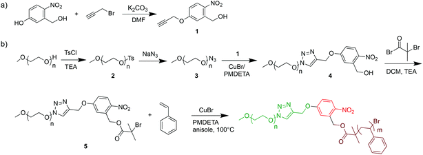
Inspired by several photo-cleavable BCPs for surface coatings and degradable systems,22,29–33 we here synthetized photo-cleavable PEO113-ONB-b-PS with ortho-nitrobenzyl moiety for solution self-assembly. The multi-step synthesis of PEO-ONB-Br macroinitiators and PEO113-ONB-b-PS is outlined in Scheme 1. For details about BCP specifics see Table 1. The length of the hydrophilic block PEO113 was kept constant for all experiments. The length of the hydrophobic PS block was varied to generate different volume fractions and thus different morphologies.| Code | BCP | M n, theo | M n | Đ |
|---|---|---|---|---|
| a Theoretical number average molecular weight measured by 1H NMR. b Number average molecular weight and polymer dispersity measured by GPC using THF as the eluent and PS standards for calibration. | ||||
| P1 | PEO113-ONB-b-PS90 | 14![[thin space (1/6-em)]](https://www.rsc.org/images/entities/char_2009.gif) 300 300 |
16![[thin space (1/6-em)]](https://www.rsc.org/images/entities/char_2009.gif) 300 300 |
1.10 |
| P2 | PEO113-ONB-b-PS165 | 20![[thin space (1/6-em)]](https://www.rsc.org/images/entities/char_2009.gif) 100 100 |
20![[thin space (1/6-em)]](https://www.rsc.org/images/entities/char_2009.gif) 900 900 |
1.13 |
| P3 | PEO113-ONB-b-PS230 | 27![[thin space (1/6-em)]](https://www.rsc.org/images/entities/char_2009.gif) 500 500 |
28![[thin space (1/6-em)]](https://www.rsc.org/images/entities/char_2009.gif) 700 700 |
1.19 |
We first synthesized the ortho-nitrobenzyl-modified PEO macroinitiator. For that, the phenol group of the 5-hydroxy-2-nitrobenzyl alcohol was modified with propargyl bromide through nucleophilic substitution in DMF mediated by K2CO3.22 The reaction yield was above 70% as verified with NMR (Fig. S1†). After purification, the terminal alkyne functionality can be used for “click reaction” to azides. The azide functionality was attached to PEO-OH in 2-steps. The terminal alcohol of PEO was first endcapped with a tosylate group in THF in the presence of triethylamine (TEA) (PEO-OTs, compound 2), which is a better leaving group.22 The degree of tosylation was determined to be >90% by 1H NMR (Fig. S3†). The tosylate leaving group was then replaced with an azide (PEO113-N3, compound 3) by nucleophilic substitution with NaN3 in DMF at 80 °C.23 Also in this case, 1H NMR confirmed a conversion higher than 90% (Fig. S4†). The PEO113-N3 was then used in the CuAAC click reaction with compound 1 in order to produce ONB-functionalized PEO-ONB-OH (4). The reaction was performed in the presence of a CuBr/PMDETA catalyst system (93% conversion, Fig. S5†).24 Finally, PEO-ONB-OH was esterified with 2-bromo-2-methylpropanoyl bromide in the presence of TEA to obtain the PEO-ONB-Br macroinitiator (compound 5). The chain end functionality reached a conversion >90%, as verified by 1H NMR. The conversion of PEO-OTs to PEO-N3 to PEO-ONB-OH was also followed by IR measurements where the characteristic band for the azide at ν = 2100 cm−1 appeared and vanished (Fig. S8†).34
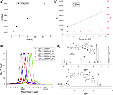
We then employed the PEO-ONB-Br macroinitiator in the ATRP of styrene to PEO114-ONB-b-PSx diblock copolymers (Fig. 1). After screening various conditions, the best conditions of polymerization were found in a mixture of styrene/anisole of 1/2 at 100 °C with CuBr and PMDETA as catalyst system. Polymerization kinetics were monitored with 1H NMR and GPC by taking aliquots of the reaction mixture with an argon-flushed syringe at specific time intervals. As visible from Fig. 1a, the polymerization showed first-order kinetics, as supported by the linear relation between monomer conversion and reaction time. Molecular weights from GPC measurements likewise showed a linear increase in Mn with conversion (Fig. 1b). The dispersity, Đ, remained low throughout the reaction increasing only slightly from Đ = 1.10 to 1.19. The GPC traces suggest full initiation as there is no noticeable macroinitiator detected e.g. in the trace after 26 h of polymerization (green in Fig. 1c). On the other hand, there is a small shoulder adjacent to the main peak that likely corresponds to a small degree of recombination (double molecular weight at peak maximum). The BCP were purified from the catalyst by silica column and from the monomer by precipitation in cold n-hexane. The block composition was determined by 1H NMR comparing the integrals of the aromatic protons of PS at δ = 6.3–7.1 ppm with the methylene protons of PEO113 at δ = 3.5–3.7 ppm (Fig. 1d).
Based on the kinetics, we synthesized three different BCPs, PEO113-ONB-b-PS90, PEO113-ONB-b-PS165 and PEO113-ONB-b-PS230, by removing larger reaction volumes at specific times (subscripts denote the number of repeating units). Fig. 2 summarizes the GPC traces of the three final BCPs and Table 1 summarizes the polymer specifics.
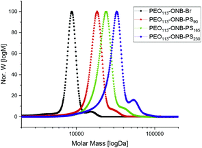 | ||
| Fig. 2 GPC traces of PEO113-ONB-Br macroinitiator, PEO113-ONB-b-PS90, PEO113-ONB-b-PS165, and PEO113-ONB-b-PS230. | ||
Photocleavage kinetics
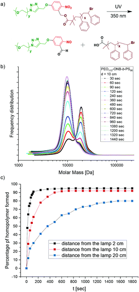
When irradiated with UV light of a wavelength of 365 nm, the PEO-ONB-b-PS cleaves at the ONB position leaving behind a terminal carboxylic acid functionality on the PS block (which later is the surface the NP). To analyse the photocleavage kinetics we recorded the percentage of cleaved BCP over time for P1. P1 was dissolved in THF at c = 1.0 mg mL−1 and the solutions were exposed to UV light with λ = 365 nm at varying distances from the lamp (d = 2 cm, 10 cm and 50 cm) for a total of 20 min. At 30 s intervals, samples were drawn and measured in GPC. The GPC results are plotted as frequency distributions, i.e. the area under a peak corresponds to the number of chains detected. Fig. 3b shows the temporal evolution of the frequency distributions at a distance of 10 cm from the UV source. After 30 s (black curve), two main peaks can be identified: the peak at higher Mn can be assigned to the uncleaved P1 BCP, while the peak at lower Mn that appears as a small shoulder corresponds to the cleaved PS90 homopolymer; the number percentage was found to be 30% after 30 s. Over the time, the peak for uncleaved P1 gradually decreased and the peak for the PS90 homopolymer increased accordingly. The peak for the PEO113 homopolymer was not visible since it overlapped with the PS90 homopolymer. However, carrying out the same experiment for the P2 BCP with a longer PS165 block, it was possible to distinguish three different peaks corresponding to the P2 BCP, as well as the PS165 and the PEO113 (Fig. S10†). At an irradiation time of 90 s about 50% of P1 was cleaved (Fig. 3b, green curve). The max cleavage is reached when the peak area remains constant, which was the case after about 14 min. About 4% of P1 BCP remains uncleaved as visible from the small shoulder, which is still present even after 20 min of irradiation. This might be attributed to side reactions during the multi-step synthesis, where unmodified PEO-OH was probably esterified directly with the ATRP initiator without ONB in between. Despite rigorous purification and testing various other reaction conditions, this peak was observed in all experiments.Since the energy input and light intensity decrease with distance between sample and light source, we also performed cleavage kinetic at distances of 2 cm and 50 cm which are summarized together with results of 10 cm in Fig. 3c. As expected, the cleavage shows slower kinetics at increased distance of 50 cm, whereas kinetics become faster at 2 cm distance. For instance, at an irradiation time of 30 s, 64% of P2 is cleaved at 2 cm distance, 30% at 10 cm, and only 12% at 50 cm. Thus, distance to the light source is a convenient handle to tune the cleavage kinetics, which may become relevant for controlling aggregation kinetics in case complementarily charged materials are added during cleavage (e.g. salt, polymers, NPs).
Self-assembly of photo-cleavable BCP micelles
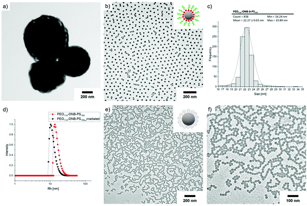
To create homogeneous populations of photo-cleavable micelles with PEO corona and PS core, the PEO-ONB-b-PS BCPs were self-assembled under various conditions. Following the classical route, the BCPs were dissolved in THF and the solvent was directly exchanged against water by dialysis. Exemplified on P2, Fig. 4a shows a TEM image of the morphology obtained for this direct solvent exchange. The P2 BCP formed large aggregates with diameter of about 500 nm and a bicontinuous inner structure. The membrane thickness is about 20 nm. Although the corona fraction of fEO = 25 wt% for P2 is not in the typical range to form bicontinuous structures,35 the morphology clearly approaches the direction of bicontinuous microparticles and cubosomes.36 These particle are likely kinetically trapped morphologies due to the fast exchange of THF with water, which reduces PS chain mobility that cannot rearrange properly to minimize interfacial energy according to the block volume ratio. Hence, for the purpose of forming uniform charge-stabilized PS NPs, the direct dialysis into water was not a suitable process. In previous studies on related PS-based BCPs, we found that organic solvents with lower polarity, e.g. isopropanol (IPA) and acetone, plasticize PS during self-assembly, which increases mobility within the core and allows for homogenization of the overall morphology.12,37–41 Therefore, P2 was molecularly dissolved in THF and first dialysed into a mixture of acetone/IPA with 80/20 v/v, before dialysis into water. As shown in Fig. 4b, the structures obtained with this slight modification to the self-assembly route changed entirely. P2 now formed spherical micelles with a very homogeneous size distribution as verified by TEM image analysis using ImageJ software.28 The software-supported analysis of 838 micelle cores on a selected image gave an average core diameter of D = 22 nm (Fig. 4c). From the core diameter, the number of chains per micelle (Nagg) can be estimated using eqn (1): | (1) |
We then photo-cleaved the corona of P2 micelles to create PS NPs in water at c = 1 mg mL−1, d = 10 cm from the UV source, and 20 min irradiation time. In order to confirm that PEO cleavage would likewise work in water, micelles of P2 were freeze-dried after irradiation at different times and redissolved in THF for GPC measurements (Fig. S11†). After 15 s of exposure to UV light, it is possible to distinguish three main peaks corresponding to the BCP at higher Mn as well as two peaks at lower Mn assigned to PEO and PS. Cleavage was completed after 15 min. After cleavage, the Rh shifted to 14 nm (black) attributed to the removal of the corona chains. The TEM image of PS NPs after cleavage in Fig. 4e confirms that NPs kept their original shape and diameter despite the missing stabilizing corona. It was not clear whether the nanoscopic dimension of the NP core would allow for shape transformation once the steric repulsion of the PEO corona was removed. In 2014, Zhao et al. have prepared PS NPs in the size range of 20–30 nm, from a ABC triblock terpolymer which can be triggered by photo and redox cleavage; however, the carboxyl acid functionality was on the cleaved corona, leaving a neutral core that undergoes to aggregation of PS NPs.42 However, the missing PEO corona does allow the PS NPs surface to touch, which leads to fusion/entanglement of the PS chains and NP merging. While DLS did not show any noticeable larger aggregates, the PS NPs clearly aggregated in TEM and formed pattern characteristic for diffusion limited aggregation (DLA).43 DLA is typically observed for metastable NPs, e.g. without sufficient electrostatic stabilization. The zetapotential of the cleaved PS NPs was determined to ζ = −36 ± 7 mV, while for the uncleaved PEO-ONB-PS micelles was found to be ζ = −10 ± 7 mV (Fig. S14†), which confirms the generation of more negative surface charges (although in a range related to metastable colloids). Since, we did not observe macroscopic precipitation of the PS NPs and patterns in TEM are always 2D, we assume this aggregation predominantly occurred on the TEM grid during drying.
To demonstrate that the synthetic route involving self-assembly of micelles and cleavage of corona is essential to achieve PS NPs with D = 22 nm, we performed a reference experiment, in which P2 was irradiated in THF before dialysis into water (Fig. S10†). In this case, spherical microparticles developed with a size range of 200 nm which reminds of latex particles charge stabilized by the generate carboxylic acid group.
The total content of carboxylic groups for the PS NPs was determined with conductometric titration according to the SCAN-test method (EN ISO 5263). The titration of PS NPs was done at a c = 1 mg mL−1 from pH 2 to pH 12 by adding 10 mL aliquots of 1 M NaOH, which neutralized the acidic groups. The conductivity was then plotted against the pH value (Fig. S13†). First, we calculated the number concentration of the nanoparticles by eqn (2):
 | (2) |
Here, m is the mass of the nanoparticle mixture, r is the radius of the nanoparticles [cm], ρ is the density of styrene (1.05 g cm−3), and V is the volume [L] of NaOH consumed in the plateau region of the graph. The number of COOH groups were calculated by eqn (3):
 | (3) |
 | (4) |
Influence of the pH
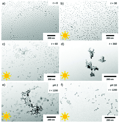
Since the PS NPs present a negative charged core surface once PEO is removed, they should respond to pH changes. The pH of a P1 solution with a micelle concentration of 1 mg mL−1 was adjusted to pH 2 and pH 10 by adding aliquots of HCl and NaOH, respectively. The micelles at pH 2 were irradiated at d = 10 cm and the resulting NPs analysed in TEM at different times. At irradiation times of 0 s and 30 s (Fig. 5a and b), the micelles remained stable without any larger agglomeration (<50% cleavage). At an irradiation time of 60 s (Fig. 5c), which corresponds to a cleavage of about 50% of corona chains, small agglomerates formed with dendritic structures reminding on DLA. At pH 2, the formed carboxylic acid groups are protonated and do not contribute to stabilization. Instead, hydrogen bonding favours aggregation between the PS cores, and thus cluster formation between NPs becomes more likely.44,45 At cleavage of approx. 80% and above, i.e. irradiation times between 360 s and 1200 s (Fig. 5d and e), visible precipitation was observed in the solution, which is confirmed by TEM. There, large irregular cluster networks with 3D structure had formed due to reaction limited aggregation (RLA). The RLA regime is characterized by clusters which diffuse and attach rigidly to each other forming much denser aggregates as compared to the those in the DLA regime. The unstable surface of protonated -COOH and the missing steric stabilization of the PEO corona both favour RLA. On the other hand, at pH 10 (Fig. 5f) even at full cleavage of the corona chains (96%, irradiation time 1200 s), PS NPs are stable and merely assemble in 2D on the TEM grid due to drying. The solution is likewise stable and does not show precipitates. At pH 10, the produced carboxylic acid on surface is deprotonated and the electrostatic repulsion contributes to stabilization.Worms and vesicles formation
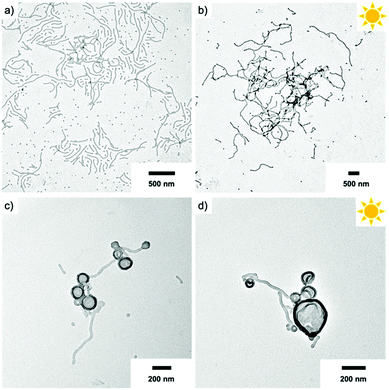
Besides spheres, other morphologies like worms and vesicles with accessible surface are also of interest. Hence, we assembled the BCPs P2 and P3 with larger PS block at varying concentration using the two-step self-assembly approach. P2 that at a concentration of 1.0 mg mL−1 formed spheres, resulted in worm-like micelles when dialysed at a concentration of 0.1 mg mL−1 (Fig. 6a). This was surprising, because decreasing the BCP concentration typically results in a transition from cylinders to spheres, whereas here the morphology changed in an inverse manner. We attribute this difference to the intermediate solvent state which provides thermodynamic equilibrium conditions before transfer to water. The cylinder micelle solution was irradiated for 20 min and the resulting particles in TEM demonstrate that the cylinder structure was retained (Fig. 6b). The intermolecular forces within the core are thus strong enough to prevent fission into spherical micelles, which could have been expected after removing the stabilizing corona. Other works demonstrated morphological transition from worms to spheres simply by addition of BCPs with shorter corona blocks.46 In our case, corona removal created anionic PS nanofibers that are shape-persistent similarly to rigid core-crystalline rod-like micelles after corona removal.47 The PS nanofibers are colloidally stable, but interparticle collision at locations with low charge density allows nanofibers to attach to each other over time, thereby promoting loose network formation. P3 with the longest PS block (PEO113-ONB-b-PS230) was also prepared at a concentration of 0.1 mg mL−1 and TEM predominantly shows polymer vesicles (Fig. 6c). In this case, UV irradiation also left the vesicular structure unaltered, which essentially provides a route to polymer capsules without a brush-like shell (Fig. 6d).AuNPs interaction
In order to address the anionic surface of the PS core, we mixed PS NPs with cationic AuNPs (d = 9 nm). Exemplified on P2 cylinder micelles at a concentration of 0.1 mg mL−1, we added a solution of Au NPs in a mixing ratio of PS NPs![[thin space (1/6-em)]](https://www.rsc.org/images/entities/char_2009.gif) :
:![[thin space (1/6-em)]](https://www.rsc.org/images/entities/char_2009.gif) Au NPs = 1
Au NPs = 1![[thin space (1/6-em)]](https://www.rsc.org/images/entities/char_2009.gif) :
:![[thin space (1/6-em)]](https://www.rsc.org/images/entities/char_2009.gif) 25. The mixture was then irradiated for 20 min and the resulting solution stirred overnight before TEM characterization (Fig. 7). As can be seen, the anionic PS nanofibers interact with the cationic AuNPs and started to form Au NP-decorated hybrids. The interaction was not yet quantitative, which might be attributed to the limited number of charges on the surface. Nevertheless, it is interesting that the attached Au NPs were able to deform the PS surface that appears to melt and wrap around the Au NPs (Fig. 7b). This suggests that the surface energy of Au NPs is large enough to change the chain packing of PS in the core, where pull out of chains and wrapping around the Au NPs could explain the grey shell around some Au NPs. We were not able to improve the NP–NP interaction despite changing several experimental conditions (pH, salt concentration, mixing ratio, irradiation time). Instead, we experienced, for instance, complete melting of the PS NPs after addition of NaCl, which further supports the soft nature of the PS core. Due to the nanoconfinement, the glass transition temperature of PS could be at or below room temperature.48
25. The mixture was then irradiated for 20 min and the resulting solution stirred overnight before TEM characterization (Fig. 7). As can be seen, the anionic PS nanofibers interact with the cationic AuNPs and started to form Au NP-decorated hybrids. The interaction was not yet quantitative, which might be attributed to the limited number of charges on the surface. Nevertheless, it is interesting that the attached Au NPs were able to deform the PS surface that appears to melt and wrap around the Au NPs (Fig. 7b). This suggests that the surface energy of Au NPs is large enough to change the chain packing of PS in the core, where pull out of chains and wrapping around the Au NPs could explain the grey shell around some Au NPs. We were not able to improve the NP–NP interaction despite changing several experimental conditions (pH, salt concentration, mixing ratio, irradiation time). Instead, we experienced, for instance, complete melting of the PS NPs after addition of NaCl, which further supports the soft nature of the PS core. Due to the nanoconfinement, the glass transition temperature of PS could be at or below room temperature.48
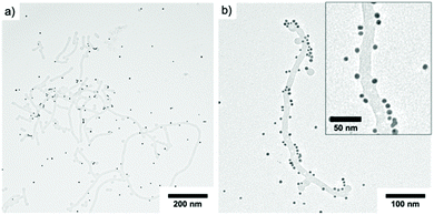 | ||
Fig. 7 TEM Characterization of PEO113-ONB-b-PS165 (c = 0.1 mg mL−1, P2) mixed with AuNPs in a ratio of 1![[thin space (1/6-em)]](https://www.rsc.org/images/entities/char_2009.gif) : :![[thin space (1/6-em)]](https://www.rsc.org/images/entities/char_2009.gif) 25. 25. | ||
In order to harvest the full potential of PS NPs for colloidal co-aggregation, cross-linking of the PS core might be a necessity to overcome the intrinsic softness that leads to strong shape-deformation after addition of complementarily charged components.
Conclusions
In this work, we synthesized PEO-ONB-b-PS BCPs with three different chain lengths of the PS block. The BCPs were self-assembled in water using a two-step dialysis processes where plasticizing organic solvents created homogeneous micelle populations in water. The resulting micelles featured spheres for P1, with worms-like micelles as predominated shape for P2, and vesicles for P3. All micelles could be converted to PS NPs by irradiation with UV light, whereas nanostructures retained their original shapes despite the loss of the PEO corona as confirmed by DLS measurements and pH-dependent aggregation. The PS NPs with negative surface charge could be co-assembled with complementarily charged Au NPs, yet, further experiments are required to optimize full surface decoration of spheres, cylinder and vesicles. PS NPs could become useful colloidal building blocks for co-assembly with other nanoparticles into superlattices by varying parameters such as pH, ratio of NPs/PS NPs, and addition of salt. We foresee that the concept of “naked” micelles can be expanded to ABC triblock terpolymers to create sophisticated patchy NPs from multicompartment micelles,49 which will be interesting for directional self-assembly and higher order NP lattices.Conflicts of interest
There are no conflicts to declare.Acknowledgements
The authors acknowledge the Imaging Center Essen (IMCES) where the TEM data was recorded. Ramzi Chakroun is acknowledged to provide the DLS data. G. Q. and A. H. G. are grateful for financial support from the DFG through the Emmy Noether Program (GR 5075/2-1).References
- M. A. Boles, M. Engel and D. V. Talapin, Chem. Rev., 2016, 116, 11220–11289 CrossRef CAS.
- J. D. Perlmutter and M. F. Hagan, Annu. Rev. Phys. Chem., 2014, 66, 217–239 CrossRef.
- R. Konecny, J. Trylska, F. Tama, D. Zhang, N. A. Baker, C. L. Brooks and J. A. McCammon, Biopolymers, 2006, 82, 106–120 CrossRef CAS.
- M. A. Kostiainen, P. Hiekkataipale, A. Laiho, V. Lemieux, J. Seitsonen, J. Ruokolainen and P. Ceci, Nat. Nanotechnol., 2013, 8, 52–56 CrossRef CAS.
- A. Korpi, C. Ma, K. Liu, A. Herrmann, O. Ikkala and M. A. Kostiainen, ACS Macro Lett., 2018, 7, 318–323 CrossRef CAS.
- V. Liljeström, A. Ora, J. Hassinen, H. T. Rekola, N. Nonappa, M. Heilala, V. Hynninen, J. J. Joensuu, R. H. A. Ras, P. Törmä, O. Ikkala and M. A. Kostiainen, Nat. Commun., 2017, 8, 671 CrossRef.
- N. Vogel, M. Retsch, C.-A. Fustin, A. del Campo and U. Jonas, Chem. Rev., 2015, 115, 6265–6311 CrossRef CAS.
- K. R. Phillips, G. T. England, S. Sunny, E. Shirman, T. Shirman, N. Vogel and J. Aizenberg, Chem. Soc. Rev., 2016, 45, 281–322 RSC.
- U. Gasser, Science, 2001, 292, 258–262 CrossRef CAS.
- S. Demirci and N. Sahiner, in Encyclopedia of Polymer Science and Technology, Wiley, 2019, pp. 1–24 Search PubMed.
- F. H. Schacher, P. A. Rupar and I. Manners, Angew. Chem., Int. Ed., 2012, 51, 7898–7921 CrossRef CAS.
- Y. Mai and A. Eisenberg, Chem. Soc. Rev., 2012, 41, 5969–5985 RSC.
- F. D'Agosto, J. Rieger and M. Lansalot, Angew. Chem., 2020, 59, 8368–8392 CrossRef.
- N. J. W. Penfold, J. Yeow, C. Boyer and S. P. Armes, ACS Macro Lett., 2019, 8, 1029–1054 CrossRef CAS.
- S. Förster, A. Timmann, C. Schellbach, A. Frömsdorf, A. Kornowski, H. Weller, S. V. Roth and P. Lindner, Nat. Mater., 2007, 6, 888–893 CrossRef.
- M. Poutanen, G. Guidetti, T. I. Gröschel, O. V. Borisov, S. Vignolini, O. Ikkala and A. H. Gröschel, ACS Nano, 2018, 12, 3149–3158 CrossRef CAS.
- T. Dotera, T. Oshiro and P. Ziherl, Nature, 2014, 506, 208–211 CrossRef CAS.
- P.-E. Rouet, C. Chomette, E. Duguet and S. Ravaine, Angew. Chem., Int. Ed., 2018, 57, 15754–15757 CrossRef CAS.
- E. Duguet, A. Désert, A. Perro and S. Ravaine, Chem. Soc. Rev., 2011, 40, 941 RSC.
- R. J. Macfarlane, B. Lee, M. R. Jones, N. Harris, G. C. Schatz and C. A. Mirkin, Science, 2011, 334, 204–208 CrossRef CAS.
- Y. Tian, Y. Zhang, T. Wang, H. L. Xin, H. Li and O. Gang, Nat. Mater., 2016, 15, 654–661 CrossRef CAS.
- J. M. Schumers, J. F. Gohy and C. A. Fustin, Polym. Chem., 2010, 1, 161–163 RSC.
- J. Babinot, E. Renard and V. Langlois, Macromol. Rapid Commun., 2010, 31, 619–624 CrossRef CAS.
- J. Li, Z. Zhou, L. Ma, G. Chen and Q. Li, Macromolecules, 2014, 47, 5739–5748 CrossRef CAS.
- M. Kang and B. Moon, Macromolecules, 2009, 42, 455–458 CrossRef CAS.
- N. G. Bastús, J. Comenge and V. Puntes, Langmuir, 2011, 27, 11098–11105 CrossRef.
- J. Hassinen, V. Liljeström, M. A. Kostiainen and R. H. A. Ras, Angew. Chem., Int. Ed., 2015, 54, 7990–7993 CrossRef CAS.
- J. Schindelin, I. Arganda-Carreras, E. Frise, V. Kaynig, M. Longair, T. Pietzsch, S. Preibisch, C. Rueden, S. Saalfeld, B. Schmid, J. Tinevez, D. J. White, V. Hartenstein, K. Eliceiri, P. Tomancak and A. Cardona, Nat. Methods, 2012, 9, 676–682 CrossRef CAS.
- S. Altinpinar, H. Zhao, W. Ali, R. S. Kappes, P. Schuchardt, S. Salehi, G. Santoro, P. Theato, S. V. Roth and J. S. Gutmann, Langmuir, 2015, 31, 8947–8952 CrossRef CAS.
- Q. Yan, D. Han and Y. Zhao, Polym. Chem., 2013, 4, 5026–5037 RSC.
- P. Theato, Angew. Chem., Int. Ed., 2011, 50, 5804–5806 CrossRef CAS.
- H. Zhao, W. Gu, E. Sterner, T. P. Russell, E. B. Coughlin and P. Theato, Macromolecules, 2011, 44, 6433–6440 CrossRef CAS.
- T. Ito, H. Coceancigh, Y. Yi, J. N. Sharma, F. C. Parks and A. H. Flood, Langmuir, 2020, 36, 9259–9268 CrossRef CAS.
- K. Sunitha, G. Unnikrishnan and C.P. Reghunadhan Nair, Polym. Adv. Technol., 2019, 30, 435–446 CrossRef.
- C. K. Wong, X. Qiang, A. H. E. Müller and A. H. Gröschel, Prog. Polym. Sci., 2020, 102, 101211 CrossRef CAS.
- Z. Lin, S. Liu, W. Mao, H. Tian, N. Wang, N. Zhang, F. Tian, L. Han, X. Feng and Y. Mai, Angew. Chem., Int. Ed., 2017, 56, 7135–7140 CrossRef CAS.
- S. Jain and F. S. Bates, Science, 2003, 300, 460–464 CrossRef CAS.
- T. L. Nghiem, T. I. Löbling and A. H. Gröschel, Polym. Chem., 2018, 9, 1583–1592 RSC.
- A. H. Gröschel, A. Walther, T. I. Löbling, F. H. Schacher, H. Schmalz and A. H. E. Müller, Nature, 2013, 503, 247–251 CrossRef.
- A. H. Gröschel, F. H. Schacher, H. Schmalz, O. V. Borisov, E. B. Zhulina, A. Walther and A. H. E. Müller, Nat. Commun., 2012, 3, 710 CrossRef.
- T. I. Löbling, O. Borisov, J. S. Haataja, O. Ikkala, A. H. Gröschel and A. H. E. Müller, Nat. Commun., 2016, 7, 12097 CrossRef.
- J. Xuan, D. Han, H. Xia and Y. Zhao, Langmuir, 2014, 30(1), 410–417 CrossRef CAS.
- M. Y. Lin, H. M. Lindsay, D. A. Weitz, R. C. Ball, R. Klein and P. Meakin, Nature, 1989, 339, 360–362 CrossRef CAS.
- N. Nonappa, J. S. Haataja, J. V. I. Timonen, S. Malola, P. Engelhardt, N. Houbenov, M. Lahtinen, H. Häkkinen and O. Ikkala, Angew. Chem., Int. Ed., 2017, 56, 6473–6477 CrossRef.
- N. Nonappa and O. Ikkala, Adv. Funct. Mater., 2018, 28, 1704328 CrossRef.
- Z. Li, M. A. Hillmyer and T. P. Lodge, Macromolecules, 2006, 39, 765–771 CrossRef CAS.
- H. Zhou, Y. Lu, H. Qiu, G. Guerin, I. Manners and M. A. Winnik, Macromolecules, 2015, 48, 2254–2262 CrossRef CAS.
- C. Zhang, Y. Guo and R. D. Priestley, Macromolecules, 2011, 44, 4001–4006 CrossRef CAS.
- A. H. Gröschel and A. H. E. Müller, Nanoscale, 2015, 7, 11841–11876 RSC.
Footnote |
| † Electronic supplementary information (ESI) available. See DOI: 10.1039/d0py01408g |
| This journal is © The Royal Society of Chemistry 2021 |

