 Open Access Article
Coupled instabilities of surface crease and bulk bending during fast free swelling of hydrogels†
Riku
Takahashi‡
a,
Yumihiko
Ikura‡
b,
Daniel R.
King
bc,
Takayuki
Nonoyama
bc,
Tasuku
Nakajima
bc,
Takayuki
Kurokawa
bc,
Hirotoshi
Kuroda
d,
Yoshihiro
Tonegawa
e and
Jian Ping
Gong
*bc
aGraduate School of Life Science, Hokkaido University, Sapporo 060-0810, Japan
bFaculty of Advanced Life Science, Hokkaido University, Sapporo 060-0810, Japan. E-mail: gong@mail.sci.hokudai.ac.jp
cGlobal Station for Soft Matter, Global Institution for Collaborative Research and Education (GI-CoRE), Hokkaido University, Sapporo 060-0810, Japan
dDepartment of Mathematics, Graduate School of Science, Hokkaido University, Sapporo 060-0810, Japan
eDepartment of Mathematics, Tokyo Institute of Technology, Tokyo, 152-8551, Japan
First published on 12th April 2016
Abstract
Most studies on hydrogel swelling instability have been focused on a constrained boundary condition. In this paper, we studied the mechanical instability of a piece of disc-shaped hydrogel during free swelling. The fast swelling of the gel induces two swelling mismatches; a surface-inner layer mismatch and an annulus-disc mismatch, which lead to the formation of a surface crease pattern and a saddle-like bulk bending, respectively. For the first time, a stripe-like surface crease that is at a right angle on the two surfaces of the gel was observed. This stripe pattern is related to the mechanical coupling of surface instability and bulk bending, which is justified by investigating the swelling-induced surface pattern on thin hydrogel sheets fixed onto a saddle-shaped substrate prior to swelling. A theoretical mechanism based on an energy model was developed to show an anisotropic stripe-like surface crease pattern on a saddle-shaped surface. These results might be helpful to develop novel strategies for controlling crease patterns on soft and wet materials by changing their three-dimensional shape.
Introduction
Intriguing surface patterns and bulk deformations are often observed in dynamic, non-equilibrium processes of soft substances.1–5 For example, intricate morphological patterns found in the human body, such as creases of the brain, wrinkles on the skin, branches in the lungs and the morphology of the gut, are formed during tissue growth.6–9 Surface creasing of hydrogels induced by fast heterogeneous swelling is also a well-known phenomenon.10,11 These phenomena are considered to be observed via mechanical instability induced during tissue growth and hydrogel swelling.12,13 Many research studies, both theoretical and experimental, have been devoted to revealing the surface crease formation mechanism using hydrogels as a model substance.14–17 The mechanical instability phenomenon has also been exploited to generate functional properties such as tunable wettability or adhesiveness, switchability of photonic properties, and cellular interaction ability.18–21 A precise understanding of the mechanical instability of gels can not only provide understanding on the morphology formation of biological tissues but also give directions to design and fabricate novel, functional soft materials.Most studies on the hydrogel swelling instability have been focused on a constrained boundary condition.14–17,22–24 That is, the gel layer is fixed to the rigid substrates that are flat or cylindrical. When a gel layer is constrained to a flat substrate, a “polygonal” surface crease pattern is formed. The crease formation is explained by the swelling mismatch between the outer and inner layers of the gel. When the gel is immersed in water, the swelling starts from the surface layer of the gel, and this layer is able to expand freely. In contrast, the inner layer swelling is restricted to the substrate of the gel. This swelling mismatch induces mechanical instability and leads to buckling. Tanaka et al. firstly revealed this buckling mechanism and developed a theory that well describes the “polygonal” crease pattern under restricted swelling conditions.25 Later, Suo et al. extensively studied the conditions for the occurrence of buckling.26
When a gel is permitted to swell in an unrestricted condition, usually a more rich and complicated phenomenon is observed. For example, a piece of sheet-shaped hydrogel shows both surface buckling and bulk shape deformation, and the surface crease pattern evolves differently from the “polygonal” pattern observed for the gel restricted to a flat substrate.14–17,22–25 This suggests the effect of mechanical coupling between bulk deformation and surface buckling. However, the understanding of unrestricted swelling is still quite limited.10,11
In this paper, we study the mechanical instability occurring during the free swelling of a piece of disc-shaped hydrogel. The paper consists of three parts. In the first part, we show experimentally the evolution of a surface crease pattern and bulk deformation during swelling. A polyelectrolyte hydrogel, which shows fast swelling kinetics, was adopted to induce mechanical instability. Semi-rigid polyelectrolyte molecules carrying opposite charges were physically entrapped in the hydrogel network as a stress sensor for analyzing the internal stress induced by mechanical instability.10,11,27 The semi-rigid macromolecules can sense the internal stress field sensitively by orienting their direction along the internal tensile direction in hydrogels. Such orientation of the semi-rigid polyelectrolyte molecules is “memorized” by forming a polyion complex with the oppositely charged network, even after swelling.10,11 So we could recall the instability pattern during heterogeneous swelling by analyzing the molecular alignment in the post-swollen sample from birefringence observation. Therefore this robust method should give us useful information which was previously unattainable. In the second part, we show that the unique crease pattern is the result of coupling of surface instability with the saddle-like bending of the gel. In the third part, we develop a theoretical mechanism to describe this mechanical coupling, based on the contraction energy initially proposed by Tanaka et al., assuming that the gel is not flat but saddle shaped with a mean curvature approaching zero (minimal surface).
Experimental section
Materials
The cationic monomer, N-[3-(N,N-dimethylamino)propyl]acrylamide methyl chloride quaternary (DMAPAA-Q) (Kohjin Co. Ltd Japan) and the photo-initiator, 2-oxoglutaric acid (OA) (Wako Pure Chemical Industries Ltd Japan) were used as received without further purification. N,N′-Methylenebis(acrylamide) (MBAA) (Wako Pure Chemical Industries Ltd Japan) was recrystallized from ethanol and used as a chemical cross-linker. Poly(2,2′-disulfonyl-4,4′-benzidine terephthalamide) (PBDT), a water soluble, anionic, semi-rigid polymer, was synthesized by an interfacial polycondensation reaction.28 The synthesized PBDT had an average molecular weight Mw of about 200![[thin space (1/6-em)]](https://www.rsc.org/images/entities/char_2009.gif) 000 g mol−1, a number average molecular weight Mn of about 150
000 g mol−1, a number average molecular weight Mn of about 150![[thin space (1/6-em)]](https://www.rsc.org/images/entities/char_2009.gif) 000 g mol−1, and a polydispersity Mw/Mn of about 1.4. These values were investigated by the GPC assay. The aqueous solution of PBDT exhibited a critical low liquid crystalline concentration, CLC*, of 2.8 wt%.29,30 For all experiments, water was deionized and purified using 0.22 μm and 5 μm membrane filters prior to use.
000 g mol−1, and a polydispersity Mw/Mn of about 1.4. These values were investigated by the GPC assay. The aqueous solution of PBDT exhibited a critical low liquid crystalline concentration, CLC*, of 2.8 wt%.29,30 For all experiments, water was deionized and purified using 0.22 μm and 5 μm membrane filters prior to use.
Synthesis of hydrogels
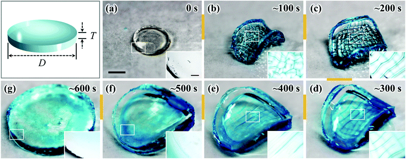
The positively charged gel was synthesized by radical polymerization of a cationic monomer, N-[3-(N,N-dimethyl amino)propyl]acrylamide methyl chloride quaternary (DMPAA-Q), and a chemical cross-linker, N,N′-methylenebis(acrylamide) (MBAA), in the presence of a small amount of semi-rigid polyanion, PBDT, as a stress sensor. In order to synthesize the hydrogel film, the reaction cells were prepared by sandwiching a 1 cm wide silicone spacer (thickness: 1 mm) along the periphery between two parallel glass plates. The aqueous pre-gel solution contained 2.0 M DMAPAA-Q, 1.0 wt% PBDT, 2 mol% MBAA, and 0.15 mol% OA (the amount in mol% is related to DMAPAA-Q). After proper mixing, the pre-gel solution was injected into the reaction cells. UV irradiation from both sides of the reaction cell (UV light intensity is 3.9 mW cm−2) was performed for 6.0 h in an argon atmosphere at room temperature to form the gel. After polymerization, the as-prepared gel, of 60 × 60 × 1.0 mm3 dimensions, was carefully removed from the glass reaction cell and cut into a disc shape (diameter (D): 6 mm, thickness (T): 1 mm) using a mechanical gel cutter (Dumb Bell Co. Ltd Japan). Young's modulus of the gel in the as-prepared state is estimated using a tensile-compressive tester (Tensilon RTC-1310A, Orientec Co.) as 0.24 MPa (see ESI,† and Fig. S1).Swelling experiment
The as-prepared disc-shaped gel was immersed in a large excess of water. A blue dye, Alcian blue (0.05 wt%), was added to the water sample to aid the visualization of the surface crease pattern. At different swelling times, the gel was taken out from the solution and photographed using a digital camera and then observed using an optical microscope. Young's modulus of the gel in the equilibrium state is estimated using a tensile-compressive tester (Tensilon RTC-1310A, Orientec Co.) as 0.11 MPa (see ESI,† and Fig. S1).Polarizing optical microscope (POM) observation
The birefringence of the gels in the equilibrium swelling state was observed using a polarizing optical microscope (POM) (Nikon, Eclipse, LV100POL) in parallel and crossed polarization modes at room temperature. Gel samples were placed on glass slides and observed from the top. All of the PBDT-containing PDMAPAA-Q gel samples exhibited a first-order white-gray birefringence color, so that a 530 nm sensitive tint plate was inserted between the polarizer and the analyzer to determine the direction of orientation of the rigid PBDT molecules.10,11,31Results and discussion
Swelling instability results
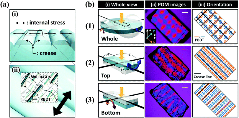
The as-prepared gel, with a diameter of 6 mm and a thickness of 1 mm, was smooth, flat, and transparent, as shown in Fig. 1(a). When the sample was immersed in water, creasing in the surface and annulus regions was immediately observed. Sharp boundaries between the bumps of creases were clearly observed as blue lines. Concomitantly to these surface and edge instabilities, the flat gel bended into a saddle-like shape (Fig. 1(b and c)). At the early stage of swelling (∼100 s), polygonal-like surface creasing was observed [inset of Fig. 1(b)], similar to the previous reports of the surface crease pattern on gels constrained on flat rigid substrates.14–17,22–25 As the swelling time increased (∼200 s to ∼400 s), the crease in the annulus region disappeared and the polygonal pattern in the central disc region changed to a stripe-like crease pattern [Fig. 1(c–e)]. The stripe creases on the two surfaces of the gel orthogonally aligned, so the blue boundary lines looked like “lattices” when being observed through the thickness of the gel [Fig. 1(d and e)]. It should be pointed out that this “lattice” like pattern was interpreted incorrectly as a lattice crease pattern in the previous studies.10,11 At a swelling time of around ∼500 s, the surface crease patterns disappeared, and the gel surface became smooth, while the saddle-like shape still remained, with a decreased curvature [Fig. 1(f)]. After ∼600 s swelling, the gel became completely smooth and flat without any deformation, similar to the shape of the as-prepared sample but with an isotropic increase in volume (8 times of the initial volume) [Fig. 1(g)]. The stripe-like crease pattern observed in this study is unique and should be attributed to the free swelling of the gel, whereupon the saddle-like bending of the gel also occurred. The vertically crossed stripes on the two surfaces of the sample are the result of coupling of the surface crease pattern and the bulk saddle-like bending that has two bending axes crossing at right angles.We further performed polarized optical microscopy (POM) observation on the post-swollen samples to analyze the internal stress built during swelling through the alignment of the semi-rigid PBDT molecules entrapped in the gel [Fig. 2(a)]. Specifically, creasing instability induces internal stress perpendicular to the crease border lines [Fig. 2(a–i)] and the PBDT molecules align along the tensile direction of the internal stress [Fig. 2(a–ii)]. The orientation of PBDT is fixed by polyion complex formation between the positively charged gel network and the negatively charged PBDT molecules as a result of dialysis of small ions from the gel during swelling in water.10,11,27 In order to investigate the correlation between the surface crease pattern and the internal stress, a piece of gel, of 7.0 mm (L) × 4.0 mm (W) × 2.0 mm (T) dimensions, was cut out from the central region of the disc-shaped sample, with the long axis of the gel piece parallel to one of the bending axes [Fig. 2b(1–i)]. The gel piece was observed through the thickness under the POM by inserting the 530 nm sensitive tint plate. A lattice-like birefringence pattern was observed [Fig. 2b(1–ii)] that can be related to the orientation of PBDT molecules that have positive optical properties [Fig. 2b(1–iii)]. Here, the blue bars and orange bars in Fig. 2b(1–iii) indicate the orientation of the PBDT molecules in the two perpendicular directions and black lines indicate the crease border lines on the two surfaces of the sample. Given the high transparency of the gel, this lattice-like birefringence pattern is attributed to the overlapping of the two individual birefringence patterns on the two surfaces of the gel, as the surface stripe crease patterns are aligned perpendicular to each other on the two surfaces of the gel. This is confirmed by the POM images of two half pieces of the sample sliced through the middle of the thickness [Fig. 2b(2–i and 3–i)]. Both POM images of the two sliced pieces show stripe-like birefringence patterns that are perpendicular to each other [Fig. 2b(2–ii and 3–ii)]. The PBDT molecules across the crease border lines are aligned perpendicular to the border lines; while PBDT molecules in between the crease border lines are aligned parallel to the border lines [Fig. 2b(2–iii and 3–iii)]. The latter indicates that the bending of the bulk gel exerts tension on the ridge surface and compression on the basin surface of the bending.32 Since the stripe-like creases on the two surfaces of the gel are perpendicular, the PBDT molecules on the two surfaces are also aligned perpendicularly, both for those across and in between the crease border lines. As a result, the whole sample exhibits the “lattice” like birefringence pattern due to the cancellation of birefringence between the border lines, as shown in Fig. 2b(1–ii and 1–iii).33
We should note that the small amount of PBDT molecules (about 0.1 wt% for a swollen sample) only serve as stress probes and they do not affect the swelling ratio, the mechanical properties (ESI,† and Fig. S2), and the crease pattern formation of the PDMAPAA-Q gel.10
Effect of coupling of two instabilities
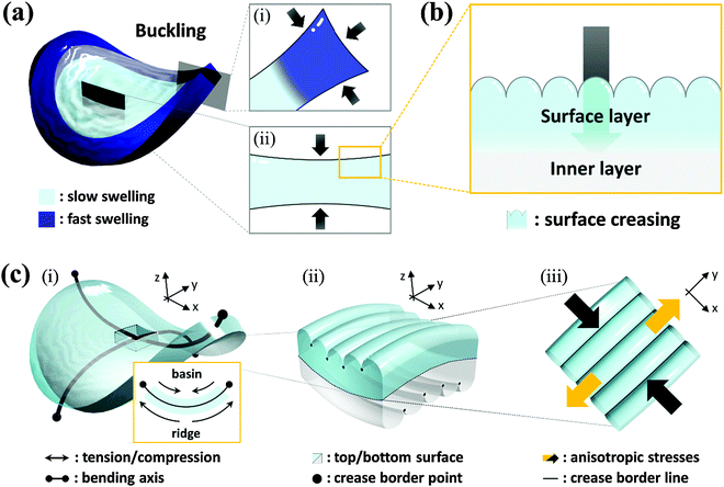
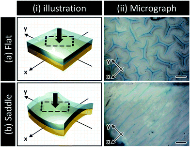
Transient surface creasing and saddle-like bending only occurred when the polyelectrolyte gel was allowed to swell very fast in water. When the gel was allowed to swell slowly in a humid vapor, no mechanical instability occurred.10 Two mechanical instabilities occur during the fast free swelling of the polyelectrolyte gel. One is the saddle-like bending induced by the swelling mismatch between the annulus and the inner region of the disc shaped gel [Fig. 3(a)], because the annulus region swells faster by taking water from the top, bottom and sides [Fig. 3(a–i)], while the inner disc region swells slower only by taking water from the top and bottom surfaces [Fig. 3(a–ii)]. When the inner radius of the annulus is larger than the radius of the disc, the annulus region is compressed, thus the saddle-like bending occurs to minimize the radius mismatch. Such kind of saddle-like bending was also reported by Klein et al., and Pezzulla et al.34,35 In particular, the investigation reported by Pezzulla et al. using a disc-shaped elastomer made from a swellable annulus and an unswellable disc is closely related to our system.35 The other is surface buckling due to swelling mismatch between the surface layer and the inner layer. The surface instability induced by this type of swelling mismatch, as clarified by previous studies, generally forms a polygonal surface creasing [Fig. 3(b)]. The unique stripe-like creasing of crossed orientation on the two surfaces observed in this work is the result of coupling of the surface instability with the saddle-like bending. When the bulk gel deforms into a saddle-like shape, the ridge of the bending releases and the basin of bending receives additional stresses [Fig. 3(c–i)], as shown by the orientation of PBDT molecules shown in Fig. 2. In the center of the saddle, at the same point, one direction is in compression and the other direction is in extension. As a result, each surface of the sample receives anisotropic stress by the saddle-like bending, which changes the isotropic polygonal surface creasing into an anisotropic, stripe-like pattern [Fig. 3(c-ii and iii)].We note that although bulk bending can induce anisotropy of surface crease, it is not necessary to give continuous stripe-like patterns. The coupling of surface instability and bulk deformation was also studied by observing the surface crease patterns of hydrogel sheets fixed, prior to swelling, onto a flat substrate and a saddle-shaped substrate, respectively (see ESI,† and Fig. S3). An isotropic polygonal surface crease was observed for the hydrogel fixed on the flat substrate, the same as reported before [Fig. 4(a)]. In contrast, an anisotropic, straight-grained surface crease was found on the hydrogel fixed on the saddle substrate [Fig. 4(b)]. The results confirm that the saddle-shaped bending induces anisotropic surface creases, but not necessarily continuous stripes. Next part, we introduce a theory to explain the formation of an anisotropic stripe creasing pattern on the hydrogel surface.
Theoretical mechanism
Herein, let us consider the mechanism of creasing on the saddle-like hydrogel surface, based on the Tanaka's theory. In the beginning, we assume that the priority order of the energy due to compression is lowest with respect to suppression of energy growth. Under this assumption, it is predicted that a thin gel in the form of a disc morphs into a saddle type minimal surface, because the stretching and bending energies are suppressed on a priority basis.35 After that, the energy due to compression will be minimized to an acceptable level. Therefore, in the following, we develop a theory by focusing on the energy due to compression of the mechanical potential energy suggested by Tanaka, and consider the influence of compression with large deformation during swelling. Tanaka's theory is not intended to describe the dynamics in the swelling gel. However, it would be allowed to apply this theory for the crease pattern formation in the process of swelling, because the time scale of crease pattern formation is faster compared to large deformation. That is, we refer the process of crease pattern formation in our system as a quasi-static transition. Furthermore, in order to fit it to our problem, we consider the energy due to compression from the geometry point of view. In ref. 25, the authors considered the restriction face as an x–y plane, and the energy due to compression, U(compression), was described as follows: | (1) |
 | (2) |
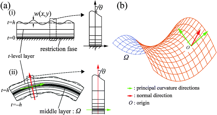
![[thin space (1/6-em)]](https://www.rsc.org/images/entities/char_2009.gif) θ, we set up the local coordinates of which the origin is some point on Ω. We choose this coordinate such that it consists of one outward normal direction and two principal curvature directions with respect to Ω (see Fig. 5b and Appendix 1). First, let us consider a point, R, on Ω. A position vector,
θ, we set up the local coordinates of which the origin is some point on Ω. We choose this coordinate such that it consists of one outward normal direction and two principal curvature directions with respect to Ω (see Fig. 5b and Appendix 1). First, let us consider a point, R, on Ω. A position vector,  , of R near the origin, O, can be described as
  uniquely. Next, let us consider an inner point, Q, of the gel. According to ref. 25, we can treat the gel as a combination of thin layers, and then, Q is contained in some layer which is named as the t-level with a parameter t as shown in Fig. 5a. Then, the position vector,
 ![[small phi, Greek, vector]](https://www.rsc.org/images/entities/i_char_e13a.gif) (x,y) of a point Q can be expressed by the following equation:
(x,y) of a point Q can be expressed by the following equation: | (3) |
![[n with combining right harpoon above (vector)]](https://www.rsc.org/images/entities/i_char_006e_20d1.gif) (x,y), and s(x,y) (or
(x,y), and s(x,y) (or ![[s with combining overline]](https://www.rsc.org/images/entities/char_0073_0305.gif) (x,y)) represent the half-thickness of the gel, an outward normal vector to Ω at R, and a displacement of the top (or bottom) surface with respect to the middle surface, respectively. Additionally, k(t;h) = sin(πt/2h) is constant with respect to x and y. It is then possible to obtain cos
(x,y)) represent the half-thickness of the gel, an outward normal vector to Ω at R, and a displacement of the top (or bottom) surface with respect to the middle surface, respectively. Additionally, k(t;h) = sin(πt/2h) is constant with respect to x and y. It is then possible to obtain cos![[thin space (1/6-em)]](https://www.rsc.org/images/entities/char_2009.gif) θ at Q from an inner product of these normal vectors. As a result, the compression energy density, UQ(compression), at Q will be expressed by the following equation (see Appendix 2):
θ at Q from an inner product of these normal vectors. As a result, the compression energy density, UQ(compression), at Q will be expressed by the following equation (see Appendix 2): | (4) |
 | (5) |
![[s with combining overline]](https://www.rsc.org/images/entities/i_char_0073_0305.gif) x → 0 is better on the bottom surface because of k < 0 (−h ≤ t < 0). The above discussion does not depend on the choice of the origin on Ω. Therefore, these results suggest that the top (or bottom) surface tends to tilt to the positive (or negative) curvature direction. The directions of the principal curvature are normal to each other, and the same applies to the internal properties (such as creases, internal stress, and so on) of the top and bottom of the gel.
x → 0 is better on the bottom surface because of k < 0 (−h ≤ t < 0). The above discussion does not depend on the choice of the origin on Ω. Therefore, these results suggest that the top (or bottom) surface tends to tilt to the positive (or negative) curvature direction. The directions of the principal curvature are normal to each other, and the same applies to the internal properties (such as creases, internal stress, and so on) of the top and bottom of the gel.
According to the above considerations, we can predict the crease pattern on the gel which is in the process of swelling with λ+ + λ− = 0. Now, we consider that the middle layer in the process of deformation can be described as (x,y,z(x,y)) in the global coordinate system. In particular, we assume that the middle layer is Scherk's minimal surface, i.e., z(x,y) can be described as follows:
 | (6) |
![[c with combining right harpoon above (vector)]](https://www.rsc.org/images/entities/i_char_0063_20d1.gif) ∓′(τ) =
∓′(τ) = ![[small xi, Greek, vector]](https://www.rsc.org/images/entities/i_char_e1cd.gif) ∓ (τ is a parameter, and prime means the derivative with respect to τ), with an appropriate initial condition, we can check the orbits of the top and bottom, which are normal to each other as shown in Fig. 6. These above considerations suggest that the creases which are normal to each other can be observed, if the large deformation at the time of swelling has the mean curvature equal to zero.
∓ (τ is a parameter, and prime means the derivative with respect to τ), with an appropriate initial condition, we can check the orbits of the top and bottom, which are normal to each other as shown in Fig. 6. These above considerations suggest that the creases which are normal to each other can be observed, if the large deformation at the time of swelling has the mean curvature equal to zero.
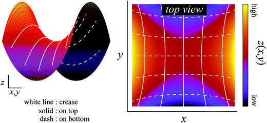 | ||
| Fig. 6 Creases on the Scherk's minimal surface. The colored surface is the Scherk's minimal surface, and the solid and dashed lines represent the creases of the top and bottom surfaces, respectively. These lines are the orbits obtained by the calculation of the differential equation from eqn (6). On any intersection, these lines are at right angles to each other when viewed along the normal direction. | ||
The theoretical prediction corresponds reasonably well with the above experimental observation, which justified the proposed mechanism. Therefore, these results indicate that surface crease patterns are affected by a large three-dimensional shape change induced by the geometric swelling mismatch.
Conclusion
In this study, we have investigated the mechanical instabilities of a thin polyelectrolyte hydrogel disc in the process of fast free swelling in pure water. During the swelling process, the gel morphed into a saddle-like shape and then the polygonal surface creases changed to stripe creases due to two swelling mismatches: surface layer/inner layers, and inner disc/outer annulus regions. The stripe creases were formed uni-directionally, and were perpendicular to each other at the two surfaces of the sample. From the detail observation of the internal stress analyzed by the orientation of semi-rigid polyanions, we found that both surface creasing and bulk deformation minimize the swelling mismatch. We further demonstrated the surface pattern change of thin hydrogel films fixed onto flat or saddle-shaped substrates and these results confirmed the mechanical coupling of surface instability and bulk deformation. Under the assumption that the gel morphs into a saddle-like shape with mean curvature of zero, it was theoretically suggested that the gel layer tends to tilt in one of the principal directions by the minimization of total energy in ref. 25. The direction of tilt of the gel layer was separated by the middle surface, therefore, the creases on the top and bottom surface were normal to each other.Acknowledgements
This research was financially supported by a Grant-in-Aid for Scientific Research (S) (No. 124225006) and Grant-in Aid for JAPS Fellows (No. 15J01078) from Japan Society for the Promotion of Science (JSPS). One of the authors, Takahashi, was supported by The Ministry of Education, Culture, Sports Science and Technology through Program for Leading Graduate Schools (Hokkaido University “Ambitious Leader's Program”).References
-
Propagation in Systems far from Equilibrium, ed. J. Wesfreid, H. Brand, P. Monnecille, G. Albinet and N. Boccara, Springer, 1988 Search PubMed
.
- X. Chen and J. Yin, Soft Matter, 2010, 6, 5667 RSC
.
- H. Yizhaq, N. J. Balmforth and A. Provenzale, Phys. D, 2004, 195, 207 CrossRef
.
- J. Kim, J. A. Hanna, M. Byun, C. D. Santangelo and R. C. Hayward, Science, 2012, 335, 1201 CrossRef CAS PubMed
.
- B. Li, Y. P. Cao, X. Q. Feng and H. Gao, Soft Matter, 2012, 8, 5728 RSC
.
- E. Hohlfeld and L. Mahadevan, Phys. Rev. Lett., 2011, 106, 105702 CrossRef PubMed
.
- J. Yin, G. J. Gerling and X. Chen, Acta Biomater., 2010, 6, 1487 CrossRef PubMed
.
- R. J. Metzger and M. A. Krasnow, Science, 1999, 284, 1635 CrossRef CAS PubMed
.
- T. Savinm, N. A. Kurpios, A. E. Shyer, P. Florescu, H. Liang, L. Mahadevan and C. J. Tabin, Nature, 2011, 476, 57 CrossRef PubMed
.
- M. Arifuzzaman, Z. L. Wu, T. Kurokawa, A. Kakugo and J. P. Gong, Soft Matter, 2012, 8, 8060 RSC
.
- M. Ariguzzaman, Z. L. Wu, R. Takahashi, T. Kurokawa, T. Nakajima and J. P. Gong, Macromolecules, 2013, 46, 9083 CrossRef
.
- M. Basa, J. F. Joanny, J. Prost and T. Risler, Phys. Rev. Lett., 2011, 106, 1 Search PubMed
.
- D. Chen, L. Jin, Z. Suo and R. C. Hayward, Mater. Horiz., 2014, 1, 207 RSC
.
- M. Guvendiren, S. Yang and J. A. Burdick, Adv. Funct. Mater., 2009, 19, 3038 CrossRef CAS
.
- V. Trujillo, J. Kim and R. C. Hayward, Soft Matter, 2008, 4, 564 RSC
.
- H. Tanaka, H. Tomita, A. Takasu, T. Hayashi and T. Nishi, Phys. Rev. Lett., 1992, 68, 2794 CrossRef CAS PubMed
.
- N. Suematsu, K. Sekimoto and K. Kawasaki, Phys. Rev. A: At., Mol., Opt. Phys., 1990, 41, 5751 CrossRef CAS
.
- P. C. Lin and S. Yang, Soft Matter, 2009, 5, 1011 RSC
.
- E. P. Chan, E. J. Smithm R. C. Hayward and A. J. Crosby, Adv. Mater., 2008, 20, 711 CrossRef CAS
.
- X. L. Zhu, Y. Zhang, D. Chandra, S. C. Cheng, J. M. Kikkawa and S. Yang, Appl. Phys. Lett., 2008, 93, 161911 CrossRef
.
- X. Jiang, R. Ferrigno, M. Mrksich and G. M. Whitesides, J. Am. Chem. Soc., 2003, 125, 2366 CrossRef CAS PubMed
.
- M. Guvendiren, J. A. Burdick and S. Yang, Soft Matter, 2010, 6, 2044 RSC
.
- E. Sultan and A. Boudaoud, J. Appl. Mech., 2008, 75, 051002 CrossRef
.
- K. Saha, J. Kim, E. Irwin, J. Yoon, F. Mormin, V. Trujillo, D. V. Schaffer, K. E. Healy and R. C. Hayward, Biophys. J., 2010, 99, 94 CrossRef PubMed
.
- T. Tanaka, S. T. Sun, Y. Hirokawa, S. Katayama, J. Kucera, Y. Hirose and T. Amiya, Nature, 1987, 325, 796 CrossRef CAS
.
- L. Jin, D. Chen, R. C. Hayward and Z. Suo, Soft Matter, 2014, 10, 303 RSC
.
- Z. L. Wu, M. Arifuzzaman, T. Kurokawa, H. Furukawa and J. P. Gong, Soft Matter, 2011, 7, 1884 RSC
.
- E. J. Vandenberg, W. R. Diveley, L. J. Filar, S. R. Pater and H. G. Barth, J. Polym. Sci., Part A: Polym. Chem., 1989, 27, 3745 CrossRef CAS
.
- T. Funaki, T. Kaneko, K. Yamaoka, Y. Oshedo, J. P. Gong, Y. Osada, Y. Shibasaki and M. Ueda, Langmuir, 2004, 20, 6518 CrossRef CAS PubMed
.
- Y. Shigekura, Y. M. Chen, H. Furukawa, T. Kaneko, D. Kaneko, Y. Osada and J. P. Gong, Adv. Mater., 2005, 17, 2695 CrossRef CAS
.
- M. F. Islam, M. Nobili, F. Ye, T. C. Lubensky and A. G. Yodn, Phys. Rev. Lett., 2005, 95, 148301 CrossRef CAS PubMed
.
- R. Takahashi, Z. L. Wu, M. Arifuzzaman, T. Nonoyama, T. Nakajima, T. Kurokawa and J. P. Gong, Nat. Commun., 2014, 5, 4490 Search PubMed
.
- A. Tagaya, H. Ohkita, M. Mukoh, R. Sakaguchi and Y. Koike, Science, 2003, 301, 812 CrossRef CAS PubMed
.
- Y. Klein, E. Efrati and E. Sharon, Science, 2007, 315, 1116 CrossRef CAS PubMed
.
- M. Pezzulla, S. A. Shillig, P. Nardinocchi and D. P. Holmes, Soft Matter, 2015, 11, 5812 RSC
.
Footnotes |
| † Electronic supplementary information (ESI) available. See DOI: 10.1039/c6sm00578k |
| ‡ These two authors contributed equally. |
| This journal is © The Royal Society of Chemistry 2016 |

