
 Open Access Article
 This Open Access Article is licensed under a
 Creative Commons Attribution 3.0 Unported Licence
Recent advancements in carbon fiber-based sustainable electrodes for flexible and wearable supercapacitors
Susmi Anna Thomas
 a,
Jayesh Cherusseri
*bc and
Deepthi N. Rajendran
*a
a,
Jayesh Cherusseri
*bc and
Deepthi N. Rajendran
*a
aDepartment of Physics, Government College for Women (Affiliated to University of Kerala), Thiruvananthapuram, Kerala 695014, India. E-mail: deepthinrphysics@gmail.com
bResearch Centre for Nanomaterials and Energy Technology (RCNMET), School of Engineering and Technology, Sunway University, No. 5 Jalan University, Bandar Sunway, 47500 Selangor Darul Ehsan, Malaysia. E-mail: drjayeshpuli@gmail.com
cSchool of Engineering and Technology, Sunway University, No. 5 Jalan University, Bandar Sunway, 47500 Selangor Darul Ehsan, Malaysia
First published on 10th July 2024
Abstract
Electrochemical energy storage devices such as rechargeable batteries and supercapacitors have replaced conventional batteries and dielectric capacitors owing to their excellent charge storage capabilities. Among them, supercapacitors (SCs) are excellent owing to their high-power density and ability to deliver high-power on demand within a fraction of a second. Furthermore, SCs utilize water-based electrolytes, and hence they are safe and reliable energy storage devices for application in portable and wearable electronic devices. However, a major challenge in the fabrication of flexible and wearable SCs is the rigidity of their electrodes due to the use of rigid metallic current collectors, hindering the successful implementation of SCs to power commercial wearable electronic devices. Thus, the flexibility of SCs is mainly attributed to their electrodes, and hence their preparation is crucial. In this review, we present the facile fabrication of SCs using carbon fibers (CFs) including carbon microfibers and carbon nanofibers. CFs are a sustainable environment-friendly material that can be employed for the fabrication of electrochemical energy storage devices. CFs function as both the electrode-active material and current collector during the fabrication of SCs. However, a major bottleneck in the use of CFs as electrode-active materials in SCs is their low specific capacitance. In this case, the specific capacitance of CF-based SCs can be enhanced via the preparation of hybrid or nanocomposite electrodes by combining CFs with other high-performing electrode-active materials such as electronically conducting polymers, nanocarbons, MXenes, and transition metal oxides. We provide a detailed discussion on various strategies adopted for the synthesis of CF-based hybrid/nanocomposite flexible electrodes for application in SCs. Furthermore, the evaluation of the electrochemical performance of CF-based SC electrodes is reviewed, with emphasis on their flexible and wearable features. This review will give readers an in-depth insight into the preparation of sustainable CF-based flexible electrodes for application in next-generation wearable SCs.
 Susmi Anna Thomas | Susmi Anna Thomas is a PhD scholar in the Department of Physics, Government College for Women, Thiruvananthapuram, affiliated to University of Kerala, Thiruvananthapuram, Kerala, India. She completed a Master's of Science with specialization in Physics in 2018 from Mar Ivanios College, Thiruvananthapuram, Kerala, India. She also obtained a Master of Philosophy in Physics from Noorul Islam Centre for Higher Education, Tamil Nadu, India in 2020. Her current research focuses on the development of new-generation 2D layered materials, such as MXenes, transition metal chalcogenides, and carbon nitrides, and their applications in the energy storage field. She has published more than 30 research articles in reputed international peer-reviewed journals. |
 Jayesh Cherusseri | Jayesh Cherusseri completed his Master's degree (MSc.) in Physics, followed by Master's degree (MTech.) in Nanomedical Sciences. He obtained a PhD with distinction in Materials Science from Indian Institute of Technology (IIT)Kanpur, India, in 2017. He was a recipient of the Dr D. S. Kothari Post Doctoral Fellowship from India in 2017 and University of Central Florida (UCF) Post-doctoral Fellowship in 2018. He has published more than 65 research publications to date with an h-index of 24. He has two Indian and one US Patent to his credit. He is an Editorial Board Member for the journal Wearable Technology, and also a member of The Royal Society of Chemistry (MRSC). Dr Cherusseri is currently working as a Senior Research Fellow at Sunway University Malaysia. His current research focuses on the synthesis and electrochemical applications of new-generation ultrathin materials. |
 Deepthi N. Rajendran | Deepthi N. Rajendran completed her Master's degree (MSc.) in Physics, followed by a Master of Philosophy in physics from University of Kerala, Thiruvananthapuram, Kerala, India. She obtained her PhD in Physics from the University of Kerala, India in 2007. She has published more than 30 research publications to date. Her current research focuses on the development of nanomaterials for energy applications, especially in solid oxide fuel cell and supercapacitors. Dr Deepthi is currently working as an Associate Professor and Research Guide in the Department of Physics, Government College for Women, Thiruvananthapuram, Kerala, India. Seven PhDs were produced under her guidance and five student are presently doing their PhD under her supervision. |
Sustainability spotlightWearable electronic devices require sustainable and safe energy storage devices to power them. In this case, flexibility, bendability, and twistability are the required features for the fabrication of wearable supercapacitors. The increasing demand for sustainable energy storage devices is manifested by UN Sustainable Development Goal: 7: Affordable and Clean Energy. Accordingly, carbon fiber-based hybrid/nanocomposite electrodes are highly sustainable materials for developing high-performance flexible and wearable supercapacitors. |
1. Introduction
Presently, the tremendous development in portable and wearable electronics has triggered the research and development of flexible energy storage devices to power them.1,2 Consequently, the increased explorations in the field of energy science and technology has helped the consumer electronics industry to emphasize the design and manufacture of consumer electronic products with features such as flexibility, portability and miniaturized size. These products exhibit various advantageous functionalities such as rollable display, on-body sensors, and wearable fabric with self-charging utility.3–5 However, efforts in the field of consumer electronics required the significant modification of energy storage systems in terms of their flexibility and safe implementation rather than merely possessing high energy density, power density and long cyclic stability. Hence, mechanical features such as flexibility, bendability, and stretchability have become crucial in the fabrication of energy storage devices for wearable electronic devices.6–8 Among the diverse energy storage devices, rechargeable metal-ion batteries and supercapacitors (SCs) are the two contemporary choices, which have evolved to satisfy the current energy demand due to the energy crisis.9–11 In this case, rechargeable metal-ion batteries such as lithium-ion batteries and sodium-ion batteries possess excellent energy densities; however, they fail to deliver high-power on demand. Alternatively, SCs exhibit a superior high-power density but low energy density. A major disadvantage in the use of rechargeable metal-ion batteries is their poor recyclability, where their disposal has become a significant issue. In contrast, SCs utilizing water-based electrolytes are environment-friendly candidates and can be sustainable devices if their components are sustainable materials. Hence, water-based SCs have become a major focus of research. Presently, with the rapid development in the field of portable electronic devices, it has become necessary to develop flexible energy storage devices such as flexible SCs, which can be bent, twisted, etc. during their operation.12 The stress–strain relationship of a flexible energy storage device can be linear elastic, anelastic or plastic.13 It is necessary for flexible SCs to possess features such as bendability, foldability, stretchability characteristics and safe operation.14,15 Recently, researchers have dedicated their efforts to introducing mechanical flexibility in rechargeable batteries by imparting flexibility to their individual components, demonstrating their potential for practical industrial applications; however, their flammability remains a major issue.16,17With respect to the features of flexible electronic devices, their power sources need to be mechanically flexible in terms of their bendable and twistable features. In this case, the bulky and cumbersome architecture of energy storage devices is not desirable given that their integration with the available portable electronic device will be difficult.18 Consequently, the development of planar energy storage devices that can easily be integrated with textile fabrics by weaving or other means has become an area of research for both materials scientists and energy researchers.19 To date, numerous studies have been reported in the literature on the design and underlying mechanism of flexible energy storage systems with the ability to undergo mechanical deformation.20 The fabrication of flexible energy storage systems for practical purposes requires each of their components to be sustainable, conformable in terms of shape, highly efficient, heat resistant, cost-effective, and scalable; however, the majority of materials cannot satisfy all these criteria.21,22 Thus, one of the major challenges encountered in the development of sustainable systems is the availability of appropriate materials. Furthermore, other features such as easy synthesis, reliability and shape-conformability are also equally important. The current developments in the field of nanostructured materials for application as electrode-active materials have facilitated the advancement of the field of electrochemical energy storage devices.23,24 The different types of electrode-active materials used include electronically conducting polymers, transition metal oxides, carbon nanomaterials, and biomass nanofibers. Among them, carbon nanomaterials have attracted the great interest due to their efficient chemical, thermal, mechanical and electronic properties.25 In the family of carbon materials, carbon fibers (CFs), including carbon nanofibers (CNFs) and carbon microfibers (CMFs), have shown great potential in the fabrication of flexible electrodes.
CFs are unique type of carbon materials, which contain a carbon content of >90 wt%. This fibril form of carbon consists of turbostratic carbon layers with graphite crystallites oriented in the fiber axis. With respect to their structural and compositional features, these materials possess extraordinary tensile strength, high modulus and stiffness values, efficient temperature and fatigue resistance, good electrical conductivity and low specific density.14 CF-based materials have been developed on an industrial scale using sources such as polyacrylonitrile (PAN) and pitch precursors, with their production dating back to 1960. Presently, CF and CF-reinforced composites have become fascinating substrates for high-performing and indispensable structural combinations. Given that CFs exhibit excellent mechanical strength and lightweight, they have become inevitable materials of choice in the fields of aerospace, automobiles, biomedicine, electrical components, etc. Commercially available CFs consist of thousands of monofilaments with a diameter in the range of 5–10 μm. In accordance with their synthesis approaches, various forms of CF-based components such as CF fabric, CF paper, CF textile, and CNF fabric have been developed recently.26 CFs prepared in both the laboratory and industry are classified in accordance with the precursors employed for their synthesis. PAN, isotropic pitch and mesophase pitch are synthesized via the spinning of individual precursors such as PAN, isotropic pitch and anisotropic mesophase pitch, respectively, followed by reactions such as stabilization and carbonization at an elevated temperature, such as 1300 °C.20 In this case, the mechanical and other fundamental properties of CFs depend on the characteristic features of the precursors used in their synthesis, and also the method adopted. Their precursors should be easily spun to a filamentary architecture, which can decompose into a stable form without melting at a slow rate. Also, the carbon content of the product should be very high after the pyrolysis procedure and produce a maximum yield.26 CFs exhibit good crystallinity in the direction of the fiber axis.
Flexible electronic devices are bendable, and sometimes twistable, and hence the SCs integrated in these devices also should possess the same features. SCs utilizing water-based electrolytes and flexible electrodes are highly desirable for wearable electronic device applications due to their safe in application and ease of integration.8 A term called “smart electronics” has also evolved recently, which has more functional features to attract the market such as Wi-Fi-charging and facial recognition monitoring.27 SCs can be coupled with renewable energy conversion technologies such as solar cells and piezoelectric/triboelectric nanogenerators for the effective utilization of waste energy for charging them instantaneously. However, the appropriate design is mandatory, and the charging capability of the energy conversion device should be matched with the electronic device that is going to utilize the power from the SC. In the case of flexible SCs, these energy conversion devices should also be flexible to realize their easy integration with wearable electronic devices. The main components of SCs are electrodes, current collector, electrolyte separator, electrolyte and sealing material. Among them, the main component determining the performance of SCs is the electrode-active material. Alternatively, the main component in flexible SCs is the supporting substrate on which the electrode-active material is deposited. During the fabrication of SC electrodes, the electrode-active material is coated on an electronically conducting substrate (such as metal sheet, metal foil, and metal foam). Hence, flexibility is actually imparted to the electrode by the substrate used in the fabrication process. In this case, if metal substrates are used for the fabrication of SC electrodes, the prepared electrodes are rigid, and hence non-flexible. Accordingly, flexible substrates are mandatory in developing flexible electrodes for SCs. The available flexible electronically conducting substrates include plastics (such as indium-doped tin oxide-coated polyethylene terephthalate), carbon cloth, CMF sheet/mat, and CNF sheet/mat. Among them, CFs are the best option as substrates for fabricating flexible electrodes due to their environment-friendliness, low specific gravity, biodegradability, sustainability, low cost, easy processing, etc. CF-based SC electrodes with a planar architecture are highly preferred for sustainable energy conversion and energy storage devices due to their extraordinary flexibility.20 CFs can easily be integrated with wearable electronic textiles by simple weaving procedures, which has boosted their demand in developing wearable SCs.11 Thus, to satisfy the requirements of current wearable devices with varying sizes and shapes, it is necessary to introduce CF-based fibrous electrodes with efficient physical, chemical, mechanical and electrochemical properties.28 CFs can be used in SC electrodes in three different ways, as follows: (i) substrate for the electrode-active material, (ii) current collector for the electrode-active material, and (iii) electrode-active material for the SC. In some cases, CFs are used as electrode-cum-current collectors for developing SCs.29 To date, numerous studies have been carried out using CF-based SCs in the literature. However, a comprehensive review in the field of CF-based SCs is lacking in the literature. This motivated us to write this review article. A graphical analysis of the number of publications based on CF-based SCs from 2004 to 2023 is presented in Fig. 1. It can be seen that an increase in the number of publications occurred in 2013, and subsequently exponential growth up to 2019, becoming stable thereafter. The reason for this saturation can be considered the limited electrode designs that can be applied to SC electrodes as well as the SC devices using CFs as flexible components. In this review article, we discuss the synthesis of CFs such as CMFs and CNFs and their successful implementation in SC electrodes. The recent progress and challenges associated with various nanocomposite electrodes based on CFs such as CF/electronically conducting polymer nanocomposites, CF/layered double-hydroxide nanocomposites, and CF/carbon nanostructure nanocomposites are emphasized, together with their preparation methods and characterization. Furthermore, the evaluation of the electrochemical performance of CF-based nanocomposite electrodes for SC application is discussed in detail using various tools such as electrochemical impedance spectroscopy, cyclic voltammetry (CV), and galvanostatic charge/discharge (GCD) measurement. The major contents of the present review are schematically shown in Fig. 2.
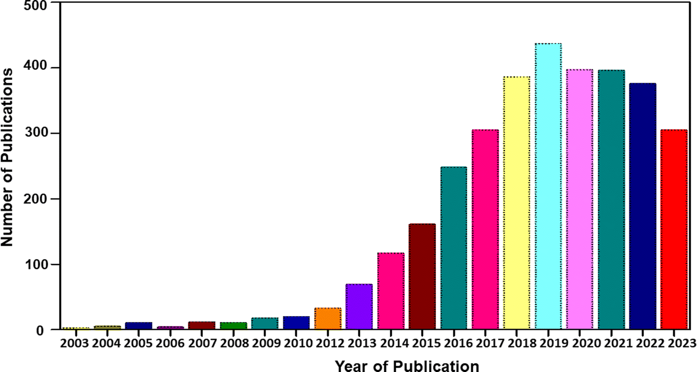 | ||
| Fig. 1 Statistical analysis of number of publications based on CFs for SC application from 2004 to 2023 [Source: Web of Science]. | ||
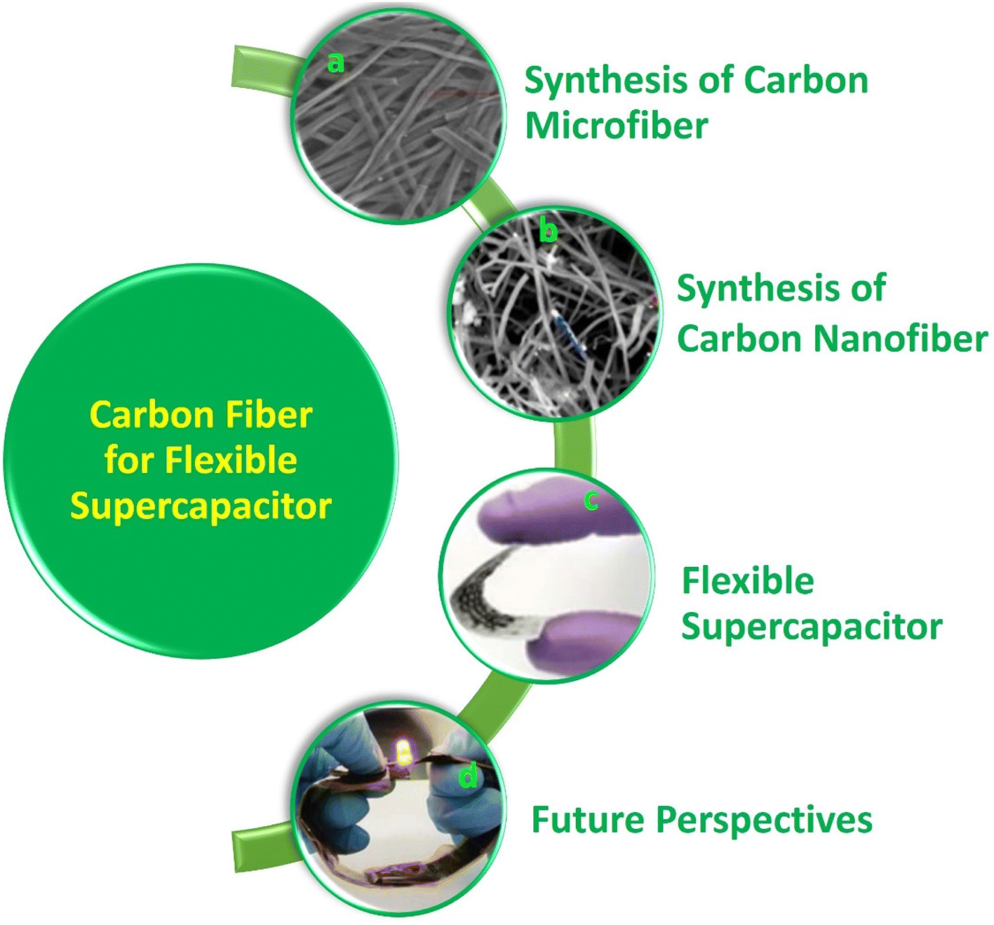 | ||
| Fig. 2 Contents of the present review: (a) SEM image of carbon microfibers. Reproduced with permission from ref. 30 Copyright (2013), Nature Scientific Reports. (b) SEM image of carbon nanofibers. Reproduced with permission from ref. 31 Copyright (2015), the American Chemical Society. (c) Digital photograph of carbon fiber-based flexible supercapacitor. Reproduced with permission from ref. 32 Copyright (2019), WILEY-VCH Verlag GmbH & Co. KGaA, Weinheim. (d) LED indicator lit by two (Ni0.1Co0.9)9Se8@CFC//PVA/KOH//rGO@carbon fiber cloth asymmetric supercapacitors connected in series. Reproduced with permission from ref. 33 Copyright (2018), WILEY-VCH Verlag GmbH & Co. KGaA, Weinheim. | ||
2. Synthesis of carbon microfibers
López et al.34 introduced the synthesis of CMF using the PAN polymer and N,N-dimethylformamide as the solvent. Here, the PAN microfibers were synthesized via electrospinning by varying the PAN concentration, which possessed high porosity after carbonization at a temperature in the range of 800–900 °C with a polymer concentration greater than or equal to 10%. Using mechanical wood fibers, Wang et al.35 synthesized lignocellulose nanofibrils (LCNF) and further subjected them to wet spinning for the preparation of CMF. Due to the presence of cellulose and lignin in LCNF, carbonization could be performed as a direct route for synthesizing CMF, thus eliminating the thermal stabilization procedure. The authors found that LCNF did not produce microfibers or filaments upon wet spinning. Thus, a smaller quantity of lignin-free nanofibers was required, such as anionic cellulose nanofibrils (TOCNF), which improved the spinnability of LCNF. Furthermore, an increase in the quantity of TOCNF influenced the properties of the spun fibers both before and after performing the carbonization steps. It was observed that TOCNF contributed to the evolution of pores through carbonization, avoiding procedures such as surface activation, electrochemical treatment and particle deposition. The surface morphology of the as-synthesized LCNF/TOCNF microfibers before and after carbonization was analysed by scanning electron microscopy (SEM), as shown in Fig. 3. With a higher TOCNF content, the microfibers were thinner and possessed a smooth surface, as shown in the first column. After the carbonization step, the microfibers shrunk in the transverse axis, as presented in second column. The high-magnification SEM image of CMF is shown in the third column in Fig. 3. The SEM images clearly show that the CMF possessed a porous morphology. The introduction of pores with an increase in the content of TOCNF resulted in glycoside bond cleavage and gasification. Saxena et al.36 synthesized CMF via chemical vapour deposition (CVD) using turpentine oil in the presence of a nickel sulfate catalyst on a graphite host. The authors of this work obtained CMF with diameter in the range of 3–5 μm with a length of 5 mm and a twisted morphology. By using natural electrospun fiber silk cocoon, Liang et al.30 synthesized one-dimensional (1D) porous CMFs. In this report, the authors synthesized a biopolymer from silkworm by an inartificial electrospinning-like approach, similar to silkworms spinning microfibers to produce a cocoon. It was observed that by applying a feasible carbonization treatment, the electrospun natural cocoon microfiber was directly transformed to a 1D CMF having an average diameter of 6 μm, as shown in Fig. 4.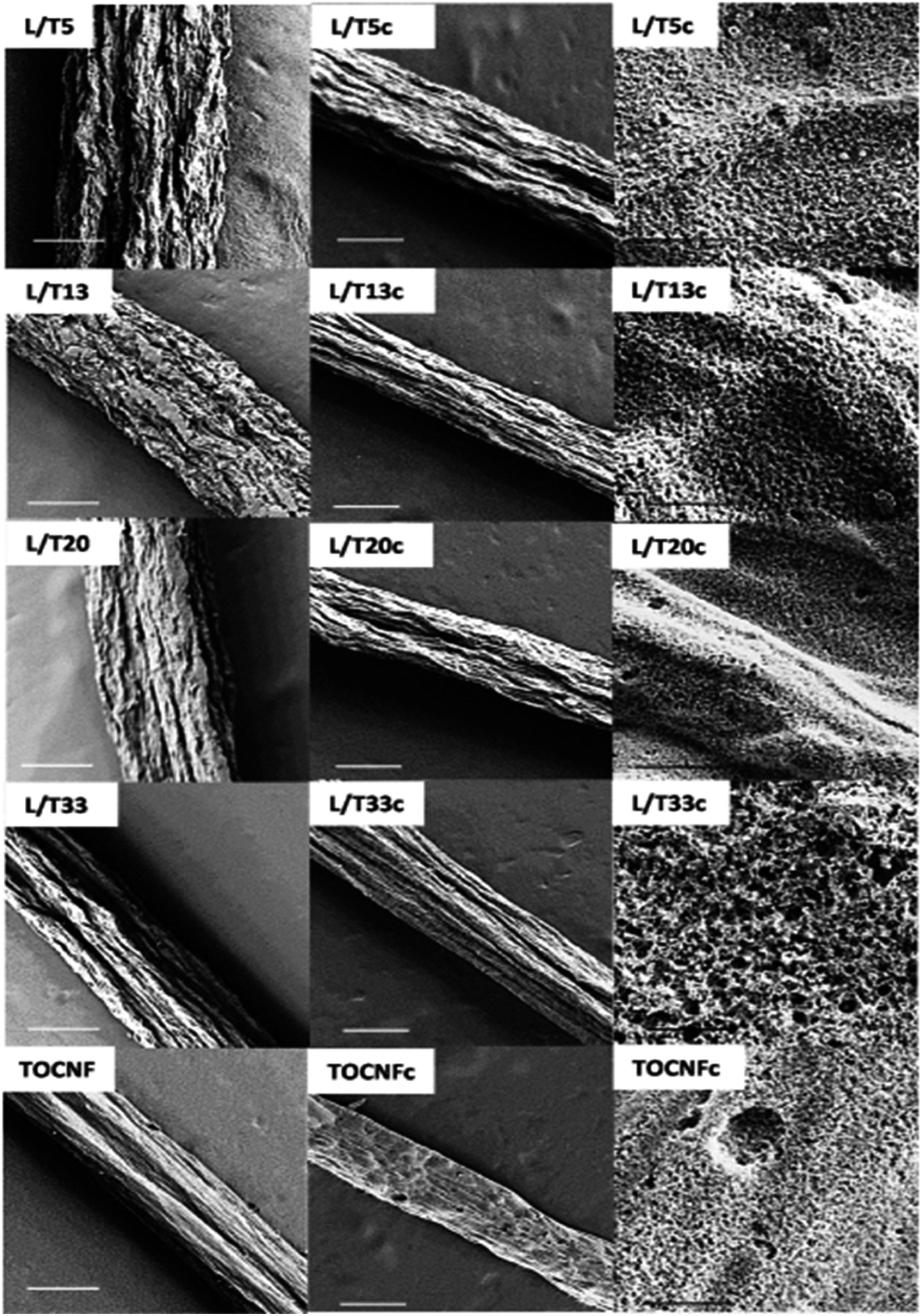 | ||
| Fig. 3 SEM images showing surface morphology of LCNF/TOCNF microfiber before (first column) and after (second column) carbonization. High-magnification SEM images of CMF are shown in third column. Reproduced with permission from ref. 35 Copyright (2020), the American Chemical Society. | ||
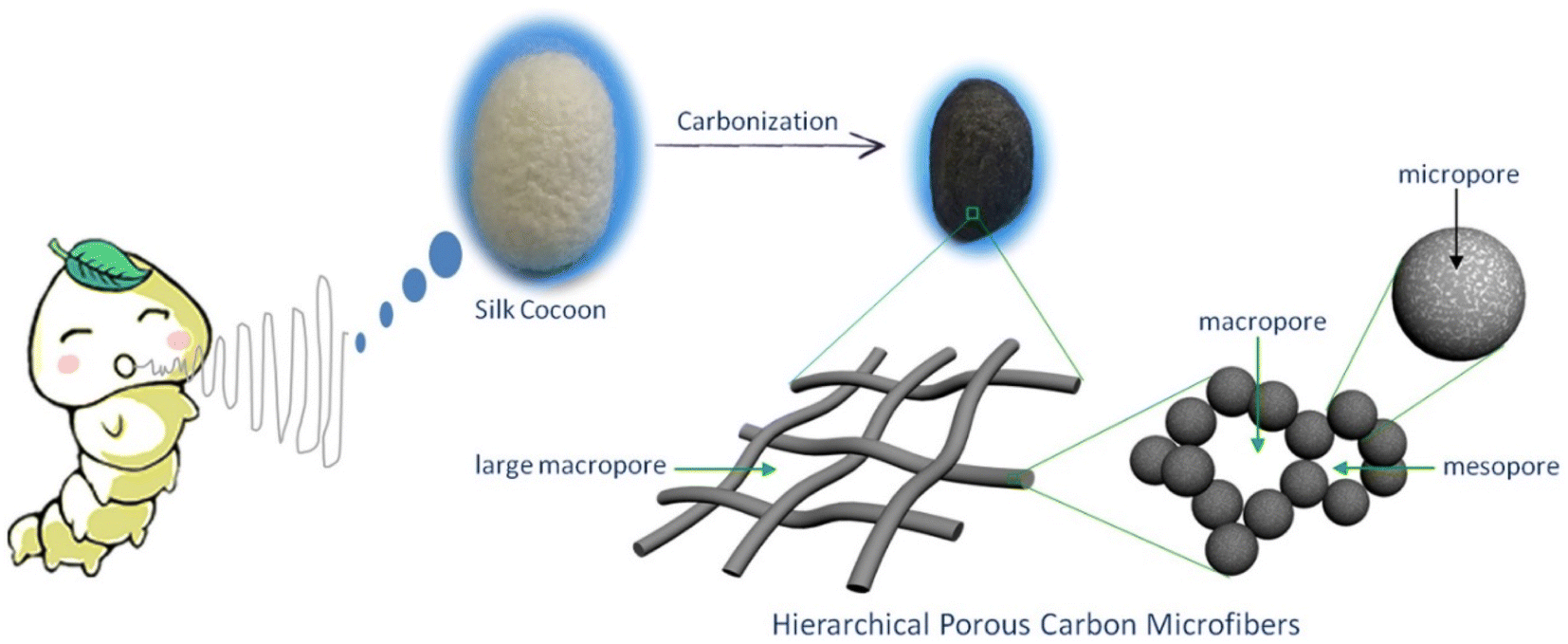 | ||
| Fig. 4 Pictorial representation of preparation of hierarchical porous CMF from silk cocoon. Reproduced with permission from ref. 30 Copyright (2013), Nature Scientific Reports. | ||
According to this study, it was found that these 1D CMFs possess numerous carbon nanoparticles with a size in the range of 10 to 40 nm, which interconnected to introduce a three-dimensional (3D) porous network architecture. These carbon nanoparticle units majorly possess a microporous structure, with compact and loose aggregation indicating a mesoporous to microporous structure. The direct carbonization of this natural biopolymer under mild conditions directed the introduction of the micro/nanostructure. Thus, the synthesis of CMF from natural polymers is environment-friendly, and hence suitable for application.
The SEM and transmission electron microscopy (TEM) images of the as-prepared porous CMF are presented in Fig. 5. After performing the carbonization treatment at a temperature of 900 °C, the prepared CMF exhibited a uniform fibrous morphology, as depicted in Fig. 5A. A CMF with a diameter of 6 μm can be observed in this image, exhibiting a smaller diameter than that of silk microfibers, which indicates that the fibrous network shrunk during carbonization due to the burning of non-carbon elements and other carbon-containing components. According to the high-magnification SEM image (Fig. 5B), it can be seen that the CMF possesses a fibrous framework, which is interconnected with a diameter in the range of 10 to −40 nm formed during high-temperature pyrolysis. The CMF obtained via this procedure possessed a prominent porous network architecture, which is clearly visible in the TEM images shown in Fig. 5C and D. Using the carbonization and activation approach, Taer et al.37 synthesized MCF from spiderweb. In this report, carbonisation was performed under a nitrogen atmosphere by adopting a multi-step heating profile to a temperature of 400 °C. The activation procedure was performed using potassium hydroxide as the activating agent. A CMF with a diameter of 0.5–25 μm was obtained and it was found that it possessed an amorphous character with a carbon content of about 84%. There are various reports in the literature describing the synthesis of CMF-based nanocomposites such as the formation with FeS using the molten salt approach38 and ZnO through a green template procedure,39 single template approach,40 etc.
 | ||
| Fig. 5 (A) and (B) SEM images and (C) and (D) TEM images of highly porous CMF. Reproduced with permission from ref. 30 Copyright (2013), Nature Scientific Reports. | ||
3. Synthesis of carbon nanofibers
CNFs are hydrophobic in nature. The surface chemistry of CNFs can be tailored with the help of various functional groups, which are used in a variety of fields such as electrochemical energy storage, sensors, and water purification. The main methods for the synthesis of CNFs include chemical vapour deposition,41–43 template-assisted approach,44–46 and filament assisted-sputtering.47,48 Ahmed et al.49 synthesized CNF via the impregnation of nickel ions (Ni2+) in powdered activated carbon. The CVD approach with the application of acetylene gas and hydrogen gas was employed for this synthesis procedure. The as-synthesized CNF possessed an average diameter in the range of 100–160 nm and the presence of Ni particles was confirmed by energy dispersive X-ray spectroscopy (EDX) analysis. Ren et al.31 reported the large-scale synthesis of CNF with high strength, flexibility and conductivity using the facile approach of electrolytic conversion of CO2 dissolved in an atmosphere of molten carbonates. The molten carbonates consisted of almost 20 mol L−1 of reducible tetravalent carbon, whereas air contains a tetravalent carbon content of only about 1.7 × 10⁻⁵ mol L−1. This approach eliminated the need for other procedures to concentrate CO2. Upon the adsorption of CO2 from the air, these molten carbonates introduced an increase in the reducible tetravalent concentration by a million-fold, which is available for splitting to carbon inside the electrolysis chamber. Here, the higher concentration of reducible tetravalent carbon sites logarithmically reduced the electrolysis potential and facilitated the transfer of charges at a lower electrolysis potential. In this procedure, CO2 was bubbled into molten carbonates, and during electrolysis, oxygen evolved at the anode, but a thick solid carbon layer was generated at the cathode (Fig. 6). It was observed that the molten carbonate split into carbon, which approached 100% coulombic efficiency, otherwise the carbonates were mixed with hydroxides. In another case, the co-generation of oxygen and carbon occurred, which sustained the formation of carbon with higher current densities and a similar phenomenon at the cathodes of carbon, platinum or steel can also be observed. The fuel cell electrolysis potential occurred at a higher temperature and higher oxide concentration with respect to a higher current density. It was found that the dissolved carbon dioxide in the molten carbonates was an uncontrolled mixture of graphite and amorphous carbon. The product introduced by cathode electrolysis, as shown in the SEM image (Fig. 6) contained controlled carbon fibers with points of metal nucleation. The majority of Ni particles were located in the nanofiber tip, but some of the particles remained at the side and not associated with the growth of the CNF. This fiber was found to be homogeneous at the cathode, possessing a diameter in the range of 200–300 nm and length in the range of 20–200 μm. Here, the fibers were synthesized through electrolysis at a 10 cm2 galvanized coil steel wire cathode and the generation of oxygen by the nickel anode in molten Li2CO3 fixed at a temperature of 730 °C was initiated at a low current of 5 mA cm−2 at the cathode, followed by a constant current electrolysis phenomenon at a higher current of 100 mA cm−2 for a duration 2 to 4 h. Here, the cooled product consisted of fibers mixed with solidified electrolyte. The resultant product readily fell in the cooled cathode when it became uncoiled. A coulombic efficiency of greater than 80% was achieved and the as-synthesized product after washing the electrolyte contained more than 80% of pure CNFs. | ||
| Fig. 6 Formation of CO2 at CNF introduced in a coiled galvanized steel cathode with nickel anode at 0.05 A, and then a constant current electrolysis at 1 A. There is no addition of Li2O to molten Li2CO3 electrolyte at 730 °C: images of (A) 10 cm2 coiled nanowire with a diameter of 0.12 cm as the cathode prior to electrolysis. Anode material is the inner wall of 20 mL Ni crucible which consists of electrolyte and (B–E) maximum variation in cathode after the removal of the carbonate electrolyte after 4 h electrolysis in molten carbonate. (F–H) SEM images at different magnifications of product removed from cooled and washed cathode. Red arrow in (H) corresponds to Ni nucleation sites and the blue arrow corresponds to the introduction at one of the Ni sites, moving in the CNF path. (I) EDS mapping in 6 μm blue arrow in the SEM image in (H). Reproduced with permission from ref. 31 Copyright (2015), the American Chemical Society. | ||
Gaud et al.50 synthesized CNF from organic waste products such as plant waste in a cost-effective and eco-friendly way. The morphological analysis of the CNF showed that it possessed a diameter in the range of 40–60 nm and length of a few micrometers. Furthermore, the as-synthesized CNF possessed a smooth surface. The EDX analysis revealed that it did not contain any impurities such as halides and oxides. Kotanjac et al.51 synthesized CNF on woven cloth using the CVD approach with a nanoscale metal catalyst and the decomposition of hot hydrocarbon vapour. This report showed that the effective production of thin single-layer fibers with dimensions of 25 × 30 cm.
4. Carbon fibers for flexible supercapacitors
SCs are new-generation electrochemical energy storage devices exhibiting high power density, high charge/discharge rates, long cycle life, etc. Based on their charge storage mechanism, SCs are classified in to three types including electrochemical double-layer capacitors, pseudocapacitors (or redox capacitors) and battery-type hybrid SCs. SCs have received significant attention in the field of energy storage devices. Wearable electronic devices require flexible and wearable SCs to power them. Thus, wearable SCs must possess features such as flexibility, bendability, and twistability to a high extent to facilitate their integration with wearable electronic devices. However, the limited availability of flexible substrates, shedding effect, and non-uniform distribution of the electrode-active materials limit their potential integration. Thus, to overcome these issues, CF-based SCs have been developed recently. In this section, we describe the CF-based nanocomposite electrodes developed for application in high-performance SCs.4.1 Carbon fiber/electronically conducting polymer nanocomposite electrodes
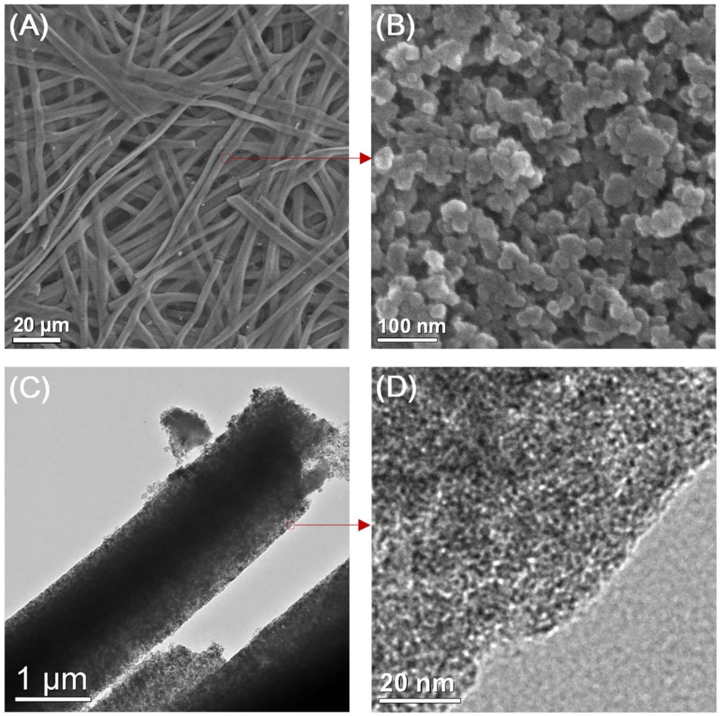
Electronically conducting polymers are the best candidates for SC electrode application due to their intrinsic conductivity, easy synthesis, good redox activity, etc. Examples of the electronically conducting polymers used in SC electrodes are polyaniline (PANI), polypyrrole (PPY), poly(3,4-ethylenedioxythiophene) (PEDOT), poly(3,4-ethylenedioxythiophene): polystyrenesulfonate (PEDOT:PSS), and poly(3-hexylthiophene). Ling et al.52 prepared a flexible, foldable and light-weight CF paper substrate using the wet-lay technique, which possessed reduced internal resistance and large porosity. Here, the wrapping of γ-MnO2 by PANI led to the formation of a core–shell architecture and a step-wise modified in situ polymerization approach was applied for the uniform distribution of the polymer. The as-prepared SC electrode exhibited a high specific capacitance of 642.5 F g−1 at a current density of 1 A g−1. Subsequently, an SC was fabricated using these nanocomposite electrodes, which delivered an energy density of 114.2 W h kg−1 at the corresponding power density of 798.6 W kg−1. This SC exhibited a capacitance retention of 81.3% even after completing 5000 cycles. The introduction of an electronically conductive polymer in a flexible substrate makes it electrically conducting, and thus it can be further used for fabricating SC electrodes with good mechanical properties. Niu et al.53 used the electrochemical polymerization technique to prepare an SC electrode comprised of a coral-like PEDOT nanotube array on textile CF (TCs). In this study, the ZnO nanowire grown on TCs acted as a sacrificial template. The polymerization of PEDOT followed by the removal of the ZnO nanowire template resulted in the creation of a composite of PEDOT nanotubes, which were vertically grown on TC. The morphology of PEDOT depended on the deposition time, as shown in the SEM image Fig. 7. During a shorter deposition time of about 5 min (Fig. 7a–c), PEDOT possessed a nanofiber-like structure with a diameter of ∼200 nm and length of ∼10 μm (Fig. 7d–f). The fibers were interconnected, generating a highly porous network of CF. In contrast, with a longer deposition duration (∼10 min), PEDOT formed a coral-like structure, where PEDOT nanorods were grown in the vertical direction, which is beneficial for the rapid transport of electrons. Similar to the ZnO nanowire structure, PEDOT showed a reduction in its diameter from base to tip (Fig. 7f). Also, the PEDOT nanotubes achieved a length in the range of tens of micrometers, where their diameter increased within the range of ∼0.5–1 μm (Fig. 7f). When the deposition time increased to 15 min (Fig. 7g–i), the diameter of PEDOT increased in a continuous manner and reached 800 nm (Fig. 7i). The coral-like PEDOT nanotube exhibited efficient conductivity, making TC@PEDOT-10 an efficient electrode material. To introduce the prepared electrode material in practical applications, the authors developed two SCs consisting of TC@PEDOT-10 as the electrode with 1 M aqueous H2SO4 and PVA–H2SO4 as electrolytes. According to this study, it was found that the two SCs exhibited ideal behaviour with a rectangular shape, possessing a similar current response at a constant rate of 50 mV s−1 (Fig. 8a), indicating the similarity in their electrochemical characteristics due to the similar ionic conductivity introduced by the PVA–H2SO4 gel electrolyte. Furthermore, the charge/discharge characteristics of the SCs were examined using GCD measurements performed at different current densities (Fig. 8b). The triangular-shaped GCD curves coincided, which represent a complete doping/de-doping reaction in a reversible manner, indicating an electrochemical method. According to the variation in the specific capacitance of SCs at different current densities (Fig. 8c), the SCs with H2SO4 aqueous electrolyte exhibited a capacitance of 22.1 F g−1 at 0.25 A g−1 and a capacity retention of 86.4% at 8 A g−1. | ||
| Fig. 7 SEM images of TC@PEDOT at various magnifications (a–c) TC@PEDOT-5, (d–f) TC@PEDOT-10 and (g–i) TC@PEDOT-15 electrodes. Reproduced with permission from ref. 53 Copyright (2020), the American Chemical Society. | ||
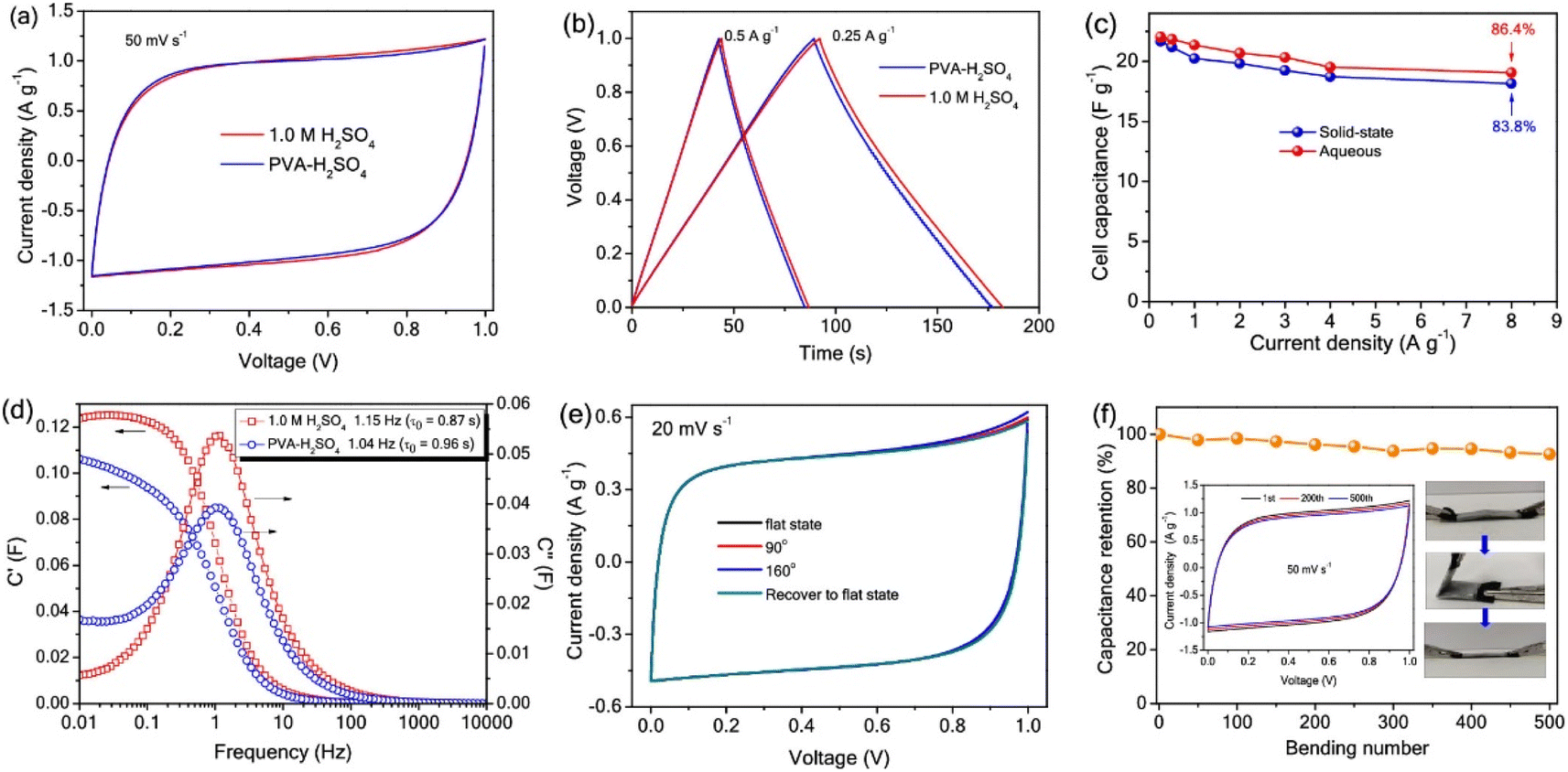 | ||
| Fig. 8 (a) CV curve at 50 mV s−1; (b) GCD profiles at 0.5 A g−1 and 0.25 A g−1; (c) rate capability diagram in the range of 0.25–8 A g−1; (d) real (C′) and imaginary part of (C′′) the specific capacitance as a function of frequency (fo); (e) CV curve representing the solid-state SC device with various bending states; and (f) capacity retention after bending the device for 500 cycles at 120°. Reproduced with permission from ref. 53 Copyright (2020), the American Chemical Society. | ||
The specific capacitance obtained for this SC was found to be higher than that of the SC fabricated using the PVA–H2SO4 gel electrolyte, which was 21.7 F g−1 with a capacity retention of 83.8%. The plot showing the variation in capacitance with respect to frequency is given in Fig. 8d. With the maximum C′′ and corresponding fo, the relaxation time constant τo of the device in both electrolytes could be introduced, revealing the shortest time taken for the discharging of all energy at an efficiency greater than 50%. The ‘τo’ values calculated for the SC utilizing H2SO4 and the SC utilizing PVA–H2SO4 gel electrolyte were 0.87 s and 0.96 s, respectively. The flexibility of the SC utilizing the PVA–H2SO4 gel electrolyte was tested by bending it at different bending angles, which recovered to its initial state after the bending test. When the SC was bent at an angle of 160°, the CV profiles corresponding to the SC utilizing the PVA–H2SO4 gel electrolyte were found to be unaltered (Fig. 8e), revealing the integrity of the SC electrode and the high flexibility of the SC. The cyclic stability of the SC utilizing the PVA–H2SO4 gel electrolyte was examined by CV analysis for 500 bending cycles at a constant scan rate of 50 mV s−1, as shown in Fig. 8f. The CV profile of the SC utilizing the PVA–H2SO4 gel electrolyte showed a retention of ∼92%, even when bending at 120° for 500 cycles.
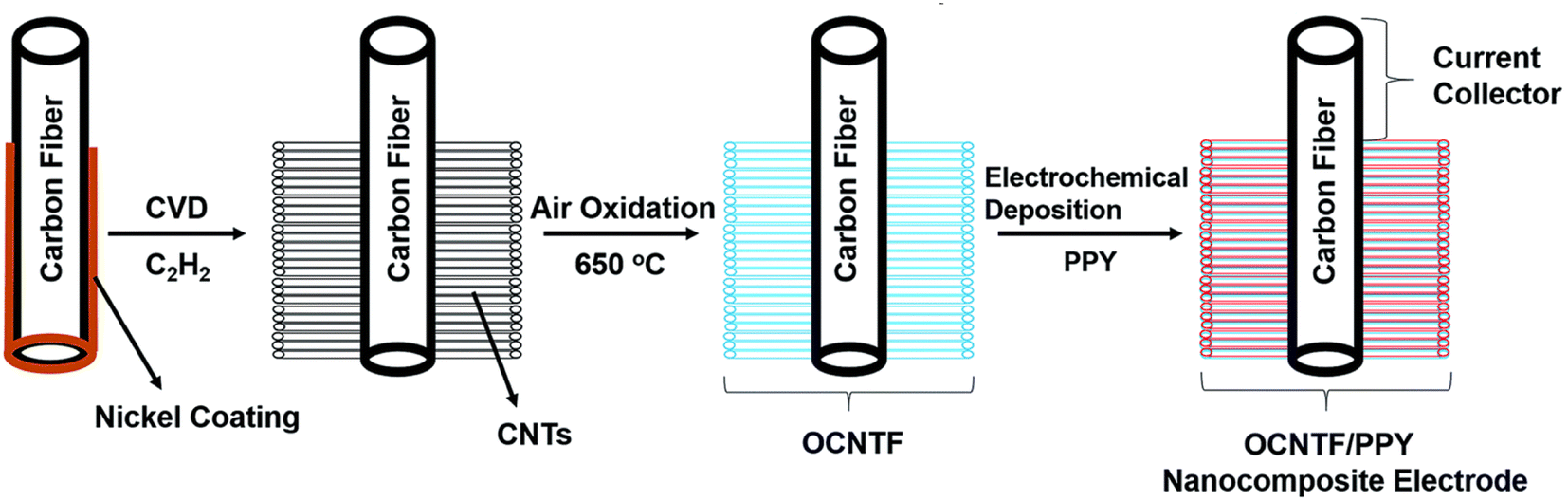
An ultra-flexible SC using oxidized carbon nanotubes (CNTs) grown on a CF (OCNTF)/PPY brush-like electrode was reported recently.54 Initially, OCNTF was synthesized using the CVD method followed by air-oxidation. Further, PPY was coated on the OCNTF substrate via the electrochemical polymerization method with varying deposition times. Fig. 9 represents the steps involved in the synthesis of the OCNTF/PPY nanocomposite.
 | ||
| Fig. 9 Pictorial representation of the fabrication of the electrode. Reproduced with permission from ref. 54 Copyright (2016), The Royal Society of Chemistry. | ||
The SEM images of the CNTs synthesized on CF by CVD are presented in Fig. 10a–c and e. According to these images, it can be observed that there was a higher density of CNTs grown on the CF substrate vertically. The oxidation of CNTs was introduced by high-temperature annealing under an oxygen environment. The SEM images of OCNTF are shown in Fig. 10d and f.
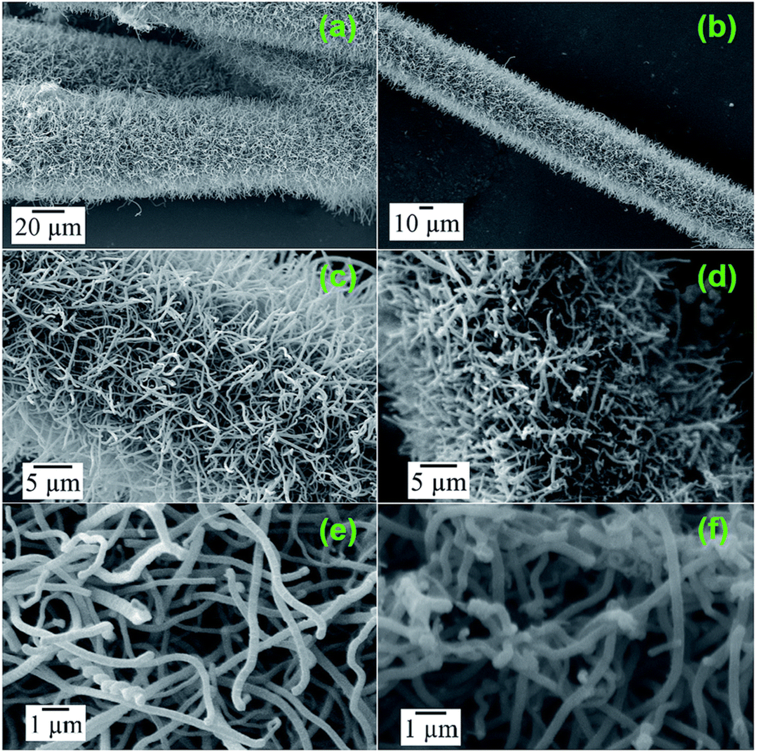 | ||
| Fig. 10 SEM images of CNTF (a–c and e) and OCNTF (d and f). Reproduced with permission from ref. 54 Copyright (2016), The Royal Society of Chemistry. | ||
The OCNTF/PPY nanocomposites were prepared at different deposition intervals. The electrochemical deposition performed at a deposition time of 50 min resulted in the formation of a dendritic-structured PPY on the OCNTF. This OCNTF/PPY nanocomposite was further used as an electrode-active material for the fabrication of a flexible SC. To analyse the flexibility of the fabricated electrode, GCD measurements were performed by bending it at different bending angles of 0° (straight position), 30°, 60°, 90°, 120° and 180° at a constant current density of 2.5 mA cm−2. According to the GCD curves (Fig. 11a), it is clear that there was no change in the curve during bending from the straight position towards 180°. A digital image that shows the bending of electrode is given as an inset image of Fig. 11a. Also, no change in its volume specific capacitance (Fig. 11b) and gravimetric capacitance (Fig. 11c) was observed during the bending towards 180°. Furthermore, the fabricated electrode exhibited a higher cyclic stability after 5000 charge/discharge cycles (Fig. 11d). A schematic diagram representing the solid-state SC fabricated with this electrode material is presented in Fig. 11e and its digital image is provided in Fig. 11f. The operation of the as-fabricated solid-state SC was studied by lighting a red light-emitting diode (LED), depicted in Fig. 11g. By using these solid-state SCs, a flexible SC module with two similar SCs connected in series was fabricated and its digital image is shown in Fig. 11h. This module was charged to a voltage of 4 V initially, and it efficiently lit a white LED (Fig. 11i). The flexibility of this SC module was verified in its straight position and by bending it at an angle of 180° (Fig. 11i and j), respectively. To verify its flexibility in terms of twisting, the fabricated SC module was rolled to the shape of a cylinder on discharging through a white LED (Fig. 11k) and no significant variation in the intensity of lighting by the LED was observed. This shows the high efficiency of the OCNTF/PPY nanocomposite-based SC for practical applications.
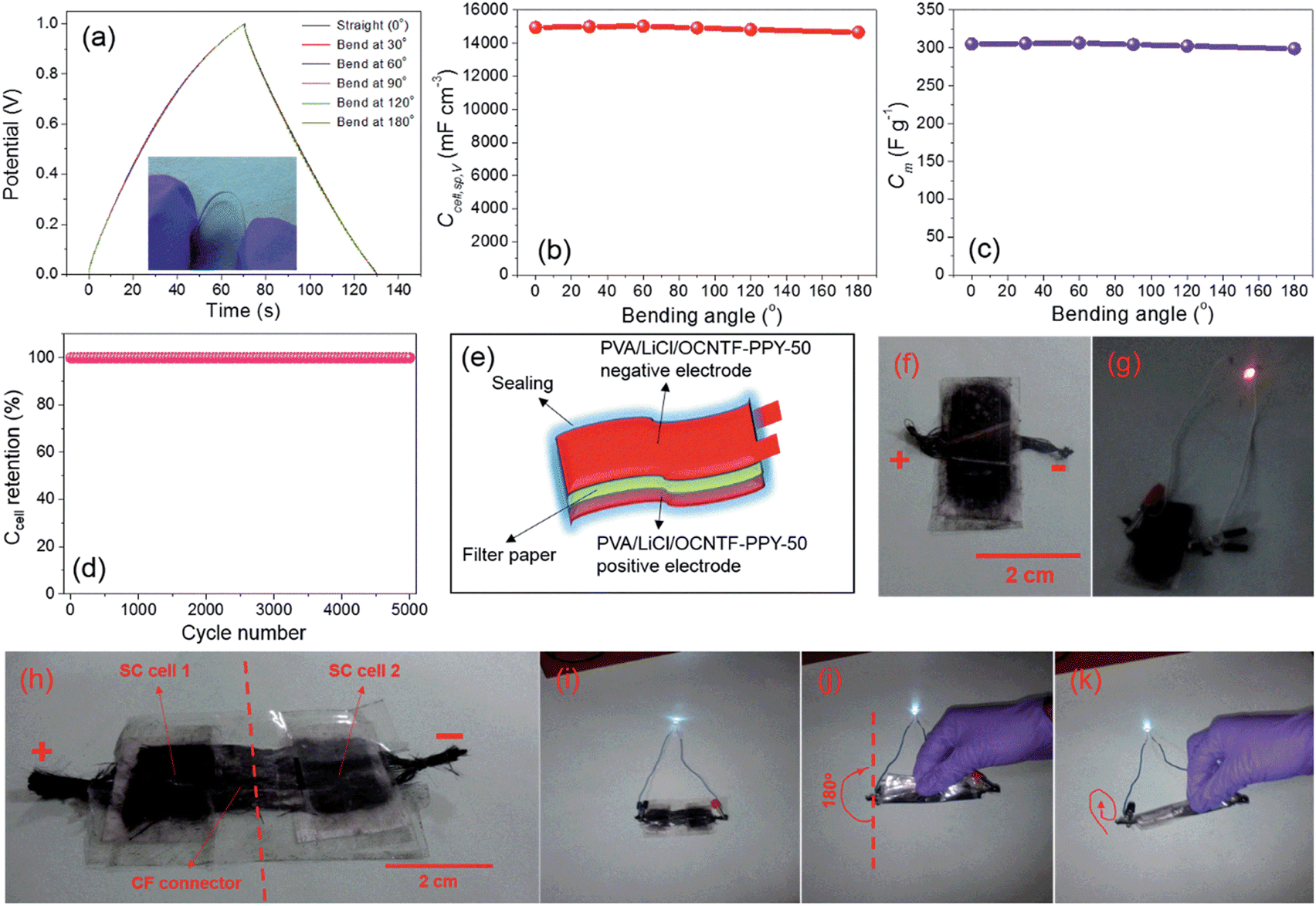 | ||
| Fig. 11 (a) GCD curve at a current density of 2.5 mA cm−2 for the fabricated SC electrode bending at different angles; (b) volumetric specific capacitance; (c) gravimetric specific capacitance at various angles; (d) capacitance retention with cycle number; (e) diagrammatic and (f) digital image of SC; (g) digital image of lighting a red LED; (h) module lighting a white LED; (i) module lighting a white LED upon bending at 180°; (j) module rolled in the form of a cylinder and (k) lighting a white LED. Reproduced with permission from ref. 54 Copyright (2016), The Royal Society of Chemistry. | ||
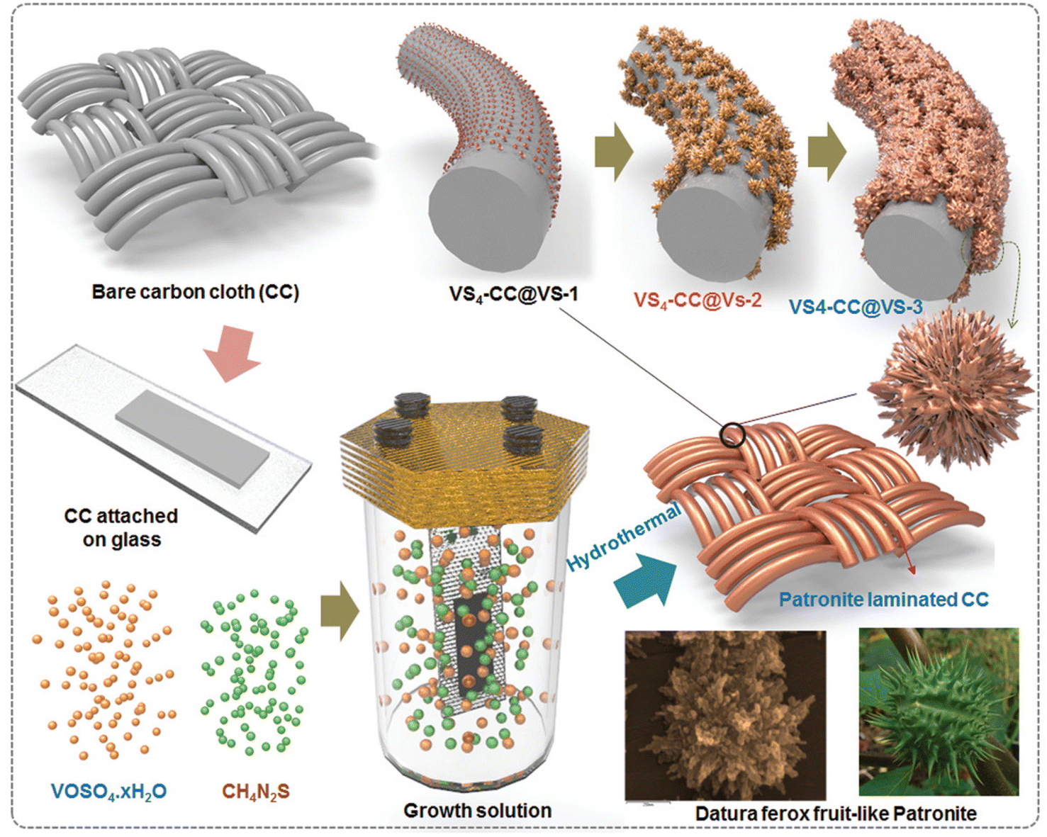
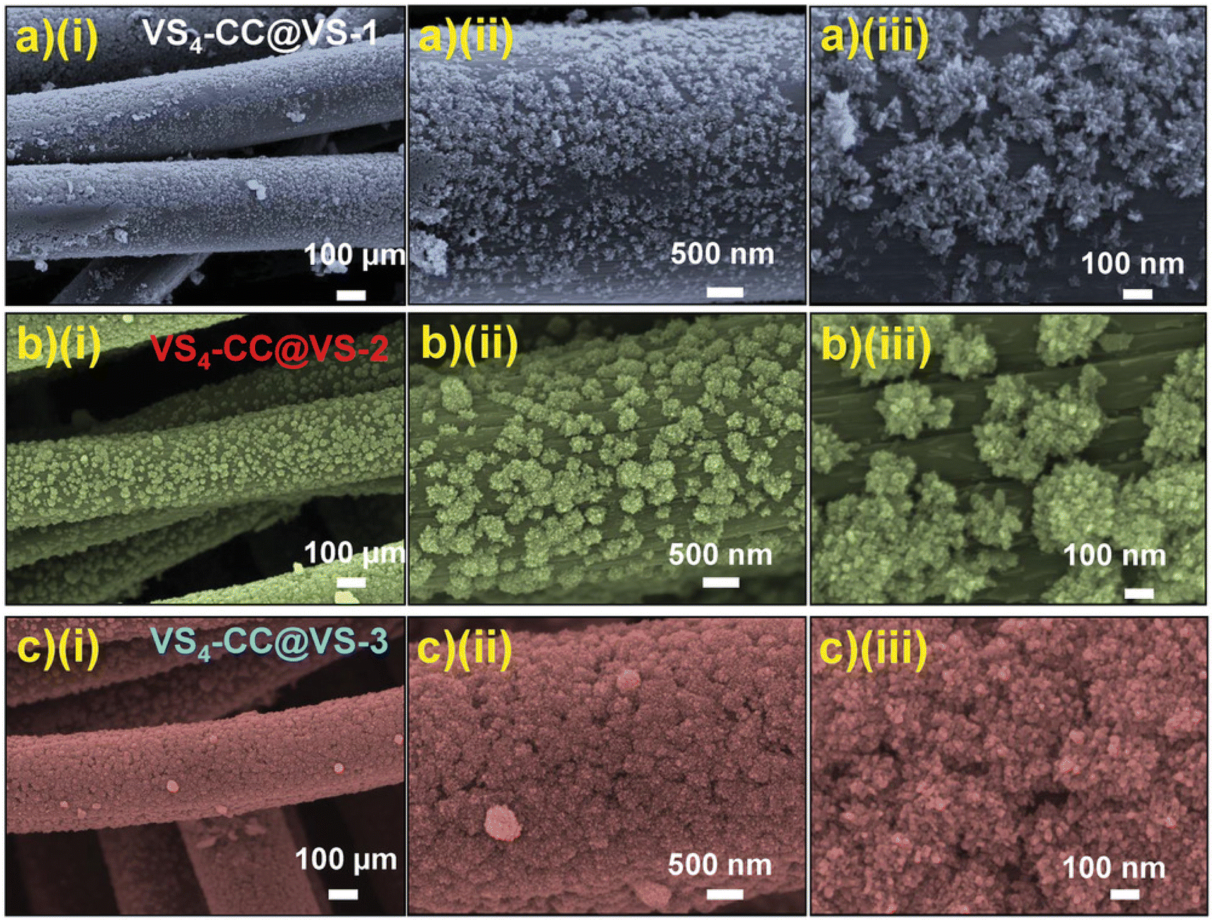
Using an aerobic pyrolysis method, Zhou et al.55 extracted CF from a CF-reinforced polymer under an oxygen atmosphere. During the pyrolysis, the reclaimed fiber surface was etched to form a groove-shaped surface and it was modified by oxygen-containing surface functional groups, which produced an enhancement in the negative potential window of the reclaimed CF to −1.4 V. By increasing the working potential to 2.4 V, it produced a capacitance retention of 93.6% after completing 10![[thin space (1/6-em)]](https://www.rsc.org/images/entities/char_2009.gif) 000 cycles in Na2SO4 aqueous electrolyte. Manikandan Ramu and team56 synthesized hierarchical VS4 nanostructures on CF via the hydrothermal method and the procedure is schematically shown in Fig. 12. During the synthesis process, the growth solution containing VOSO4·xH2O and C2H5NS with CH3COOH as a complexing agent was prepared. This resulted in the creation of a VS4 nanostructure without any binder on CF cloth substrate with good adhesion. The authors of this work synthesized various samples under different growth conditions by varying the pH, which were labelled as VS4-CC@VS-1 (pH 2.5), VS4-CC@VS-2 (pH 2.3) and VS4-CC@VS-3 (pH 2.1). The microstructure and morphology of these samples were studied by FESEM imaging, as shown in Fig. 13.
000 cycles in Na2SO4 aqueous electrolyte. Manikandan Ramu and team56 synthesized hierarchical VS4 nanostructures on CF via the hydrothermal method and the procedure is schematically shown in Fig. 12. During the synthesis process, the growth solution containing VOSO4·xH2O and C2H5NS with CH3COOH as a complexing agent was prepared. This resulted in the creation of a VS4 nanostructure without any binder on CF cloth substrate with good adhesion. The authors of this work synthesized various samples under different growth conditions by varying the pH, which were labelled as VS4-CC@VS-1 (pH 2.5), VS4-CC@VS-2 (pH 2.3) and VS4-CC@VS-3 (pH 2.1). The microstructure and morphology of these samples were studied by FESEM imaging, as shown in Fig. 13.
 | ||
| Fig. 12 Pictorial representation of the procedure for the synthesis of ferox-fruit like patronite (VS4) nanostructure on a flexible carbon cloth substrate in growth medium with controlled pH. Reproduced with permission from ref. 56 Copyright (2020), WILEY-VCH Verlag GmbH & Co. KGaA, Weinheim. | ||
 | ||
| Fig. 13 FESEM images of (a) VS4-CC@VS-1; (b) VS4-CC@VS-2, and (c) VS4-CC@VS-3 samples at various magnifications. Reproduced with permission from ref. 56 Copyright (2020), WILEY-VCH Verlag GmbH & Co. KGaA, Weinheim. | ||
The SEM images of VS4-CC@VS-1 are shown in Fig. 13a(i–iii). In this sample, VS4 possessed nanospike-like agglomerated particles, which exhibited a non-uniform distribution on the CF cloth substrate. With double the concentration, VS4-CC@VS-2, the increased growth of VS4 on the CF cloth was observed, as depicted in Fig. 13b(i–iii). Discrete nanospike bunches were visible in the first sample, which exhibited a flower-like morphology. Due to the non-uniformity of their alignment on the CF cloth surface, the concentration was further increased and VS4-CC@VS-3 was prepared. Fig. 13c(i–iii) show the SEM images, indicating large growth with a Datura ferox fruit-like morphology and the availability of numerous electrochemically active sites. Further, SC electrodes were fabricated using these three samples and their electrochemical performances were examined. The electrochemical performance of the SC electrodes was analysed in a three-electrode cell using 1 M 1-ethyl-3-methylimidazolium trifluoromethanesulfonate in acetonitrile ([EMIM][Otf]) ionic liquid electrolyte. A pictorial representation of the fabrication of the symmetric SC constructed using the VS4-CC@VS-3 electrodes is presented in Fig. 14a. The comparison of the CV curves of the three SC electrodes (VS4-CC@VS-1, VS4-CC@VS-2 and VS4-CC@VS-3) showed that the electrode-active materials exhibited a pair of redox peaks and possessed a quasi-rectangular shape, indicating their pseudocapacitive charge storage (Fig. 14b). The comparison of the GCD measurement of the three SC electrodes (VS4-CC@VS-1, VS4-CC@VS-2 and VS4-CC@VS-3) showed that the electrode-active materials exhibited symmetric with nearly distorted triangular curves, showing their reversibility and pseudocapacitive nature, as shown in Fig. 14c. The CV curves obtained for VS4-CC@VS-3 at different scan rates are presented in Fig. 14d. These CV curves consist of broad redox peaks, arising due to the intercalation/deintercalation of [EMIM]+-ions, which represents that this SC electrode is pseudocapacitive in nature. The GCD curves obtained for VS4-CC@VS-3 at different current densities (1 to 10 mA cm−2) are shown in Fig. 14e. The charge/discharge cures show that the SC electrode exhibited an efficient electrochemical performance.
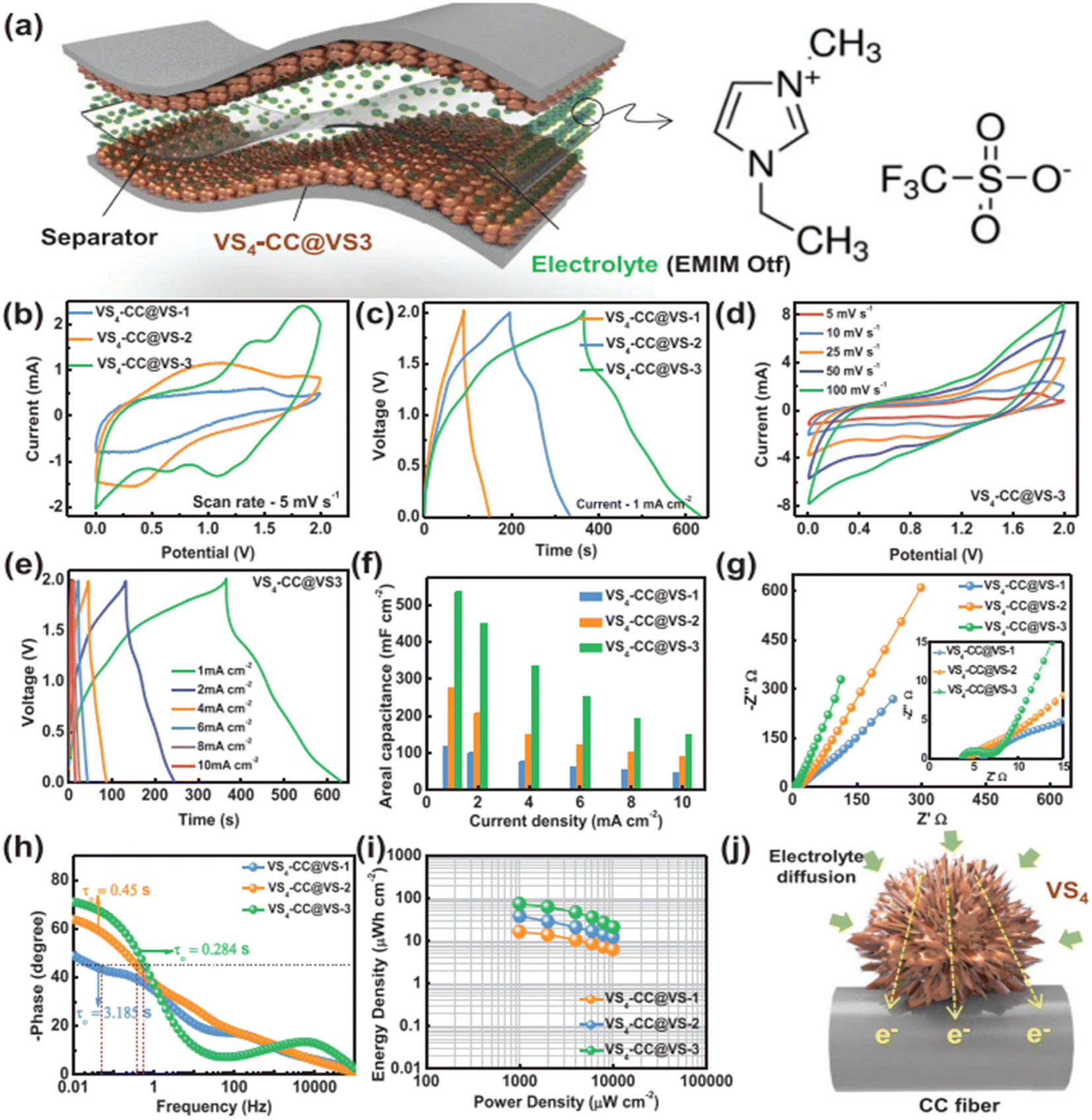 | ||
| Fig. 14 (a) Pictorial representation of symmetric SC with ionic liquid electrolyte; (b) CVs of electrode at a scan rate of 5 mV s−1; (c) GCD curve at a current density of 1 mA cm−2; (d) CV at different scan rates; (e) GCD at different current densities; (f) variation in the area specific capacitance at various current densities; (g) Nyquist plot and (h) Bode plot of device; (i) Ragone plot of the symmetric device; and (j) pictorial representation of mechanism of the binder-free electrode SC device with VS4-CC@VS-3. Reproduced with permission from ref. 56 Copyright (2020), WILEY-VCH Verlag GmbH & Co. KGaA, Weinheim. | ||
The area specific capacitance obtained for the three SC electrodes was calculated using the GCD curves measured at different current densities, as plotted in Fig. 14f. The SCs possessed the maximum area specific capacitance of 119 mF cm−2 for VS4-CC@VS-1, 277 mF cm−3 for VS4-CC@VS-2 and 536 mF cm−3 for VS4-CC@VS-3, where it can be seen that among them, the VS4-CC@VS-3 SC exhibited the best performance. Furthermore, the VS4-CC@VS-3 SC possessed area specific capacitances of 536, 452, 335, 254, 194, and 149 mF cm−2 at a current density of 1, 2, 4, 6, 8, and 10 mA cm−2, respectively. These superior electrochemical characteristics of VS4-CC@VS-3 SC are attributed to the dense growth of VS4 nanoflowers on CF cloth, which created a large interaction area for the rapid diffusion of the electrolyte-ions. The Nyquist plot (Fig. 14g) and Bode plot (Fig. 14h) showed that the VS4-CC@VS-1, VS4-CC@VS-2, and VS4-CC@VS-3 SCs exhibited a series resistance of 4.629, 4.14, and 3.765 Ω cm2, respectively. The Ragone plot of these three SCs (Fig. 14i) revealed that the VS4-CC@VS-3 SC exhibited the highest energy density of 28.6 W h kg−1 at the corresponding power density of 9340 W kg−1. This report envisages the design of a binder-free electrode that facilitates the rapid diffusion of electrolyte ions, thereby delivering a high performance. A schematic representation of the mechanism of the binder-free VS4-CC@VS-3 SC electrode is depicted in Fig. 14j.
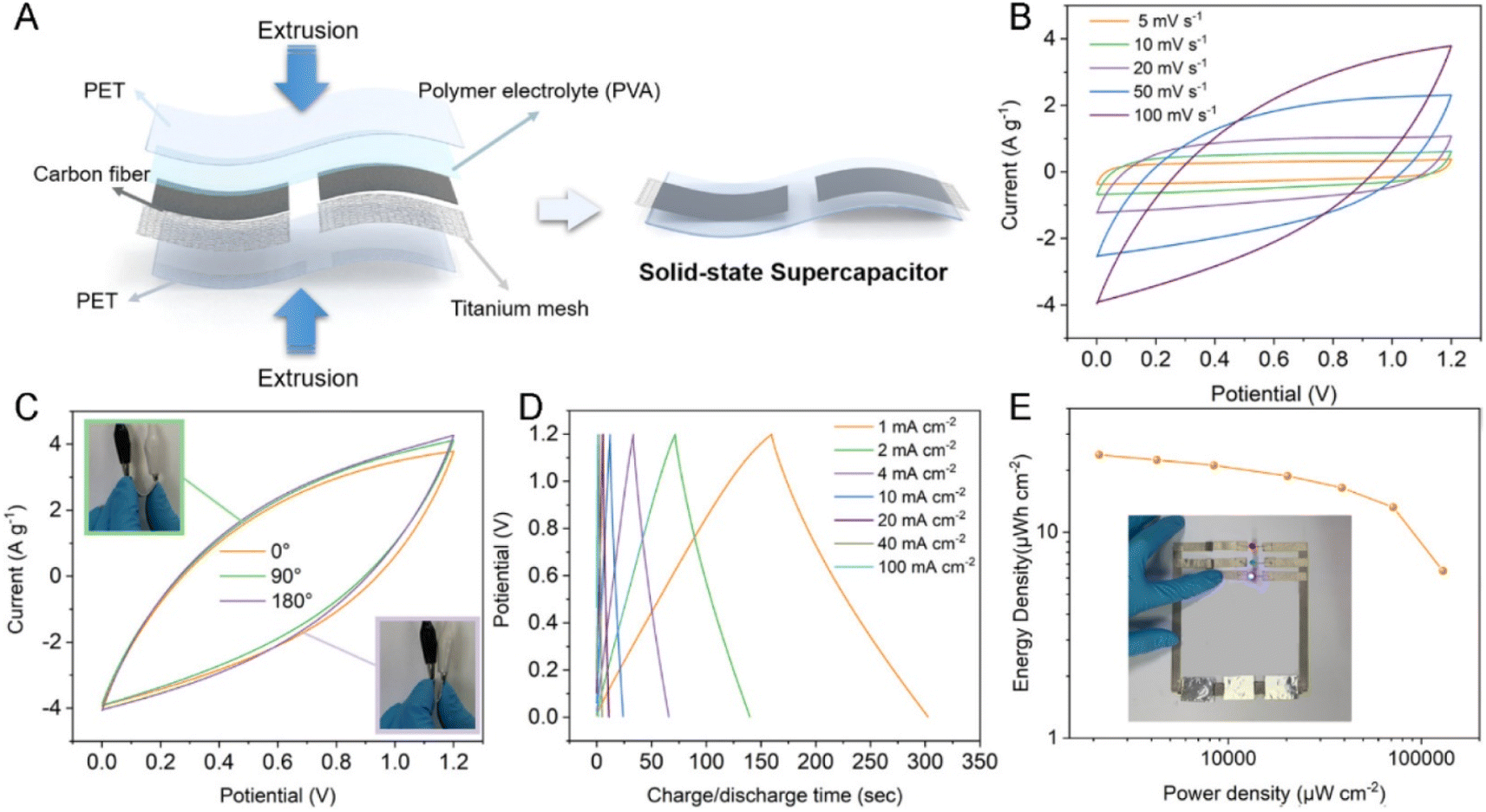
CFs have prominent applications in the energy field due to their large surface area, high temperature tolerance, reduced thermal expansion coefficient, high electrochemically active interfaces and 1D pathway for the transportation of electrons. However, the difficulty in synthesizing CNF-based SC electrodes via green and cost-effective methods hinders their further exploration. Li et al.57 suggested a copolymerization approach, where an oxygen-rich monomer named itaconic acid (IA) was introduced in the molecular chain of PAN, which did not damage the uniformity of the trapezoidal structure formed during the thermal stabilization approach. Alternatively, it was found to create a large number of functional groups such as oxygen-containing functional groups, as shown in Fig. 15A and B. It was found that the carbonization procedure led to the formation of a microporous structure by creating a vacancy effect in CNF. The degradation of a segment increased with the substitution of an N atom, introducing higher redox activity in the material. After a stabilization period of 48 h, the prepared CNF membrane exhibited high flexibility and was found to stable even when bent at a bending angle of 180° (a digital image of the same is given as an inset image of Fig. 15C). The SEM images of CNF obtained at different magnifications are depicted in Fig. 15C–E. The HRTEM images of CNF exhibited a less graphitic structure, as can be seen in Fig. 15F and G. The selected area electron diffraction pattern (SAED) of CNF possessed diffused rings, showing its amorphous nature (Fig. 15H). The elemental mapping analysis showed the even distribution of carbon, oxygen and nitrogen in CNF (Fig. 15I). The authors of this work fabricated a flexible symmetric SC using gel electrolyte, as schematically shown in Fig. 16A. The gel electrolyte exhibited low ionic conductivity, and hence a small deviation in the CV curves were observed from the normal rectangular shape but it still maintained symmetry even at a scan rate of 100 mV s−1 (Fig. 16B). Fig. 16C shows the CV curves obtained at different bending angles such as 0°, 90°, and 180°, where no variation in the area under the curve can be observed and the digital images of bending at 90° and 180° is given as inset images. This shows the excellent stability of the SC even under severe bending at 180°. The GCD curves obtained for the solid-state SC are shown in Fig. 16D, which present linearity with a symmetric triangular shape. The Ragone plot of the assembled SC is depicted in Fig. 16E, which exhibits an area power density of 2142 μW cm−2 with the corresponding energy density of 23.8 μW h cm−2. The inset image of Fig. 16E shows the lighting-up of a blue LED powered by the as-fabricated SC.
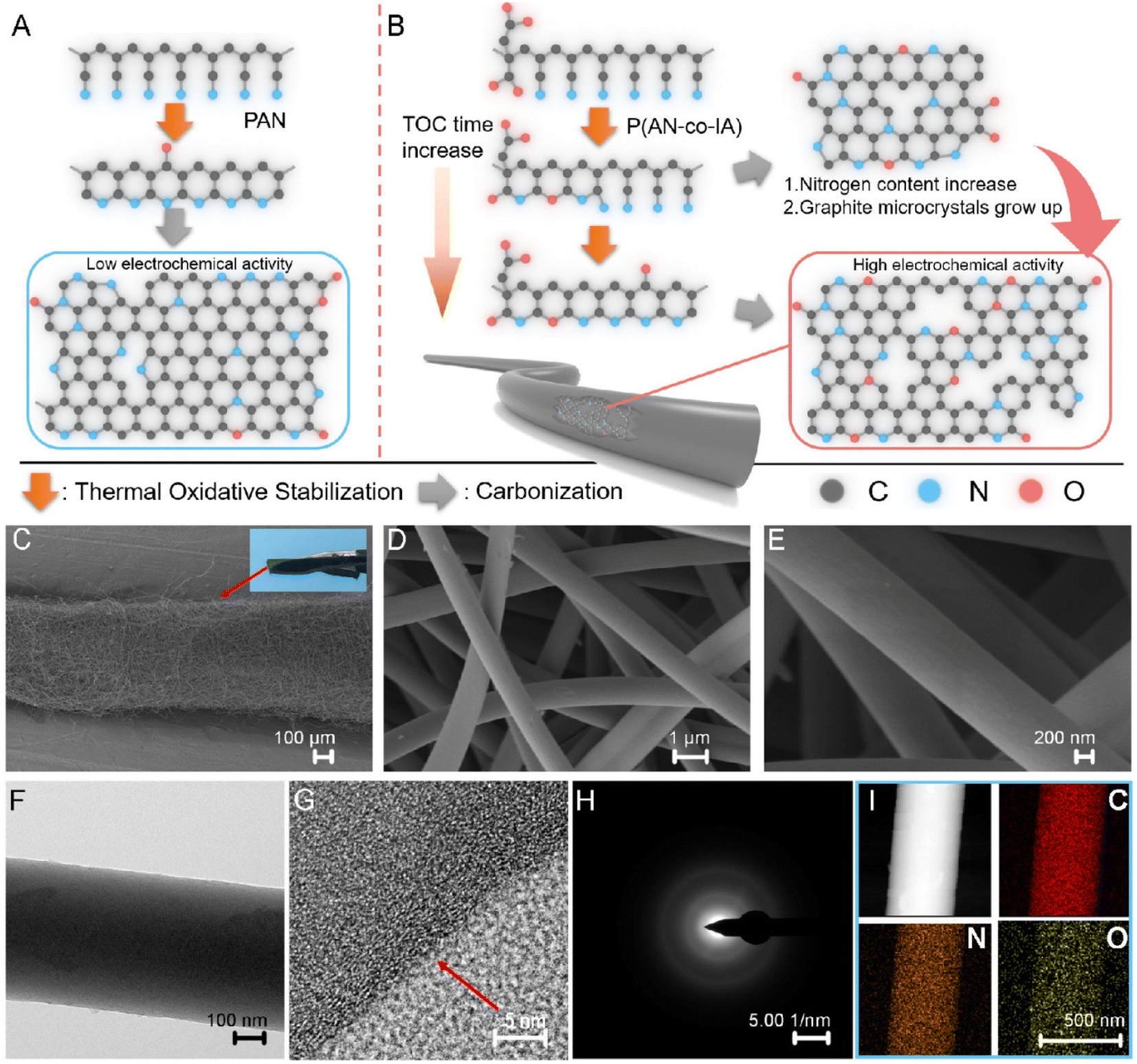 | ||
| Fig. 15 (A) Pictorial representation of carbonization procedure of PAN and (B) image of PAN copolymer carbonization. When the cyclization of precursor increases, the pre-nitrogen content and material graphitization also increase. SEM images of (C–E) carbonized CNF and image of a piece of CNF. HRTEM images of CNF (F and G), (H) SAED image; and (I) electron loss spectroscopy (EELS) elemental mapping. Reproduced with permission from ref. 57 Copyright (2021), the American Chemical Society. | ||
 | ||
| Fig. 16 (A) Preparation of SC; (B) CV curve of device; (C) CV curve of device at different bending angles (inset images show the digital images of bending at 90° and 180°); (D) GCD curve; and (E) Ragone plot with inset showing a blue LED constructed powered by the device. Reproduced with permission from ref. 57 Copyright (2021), the American Chemical Society. | ||
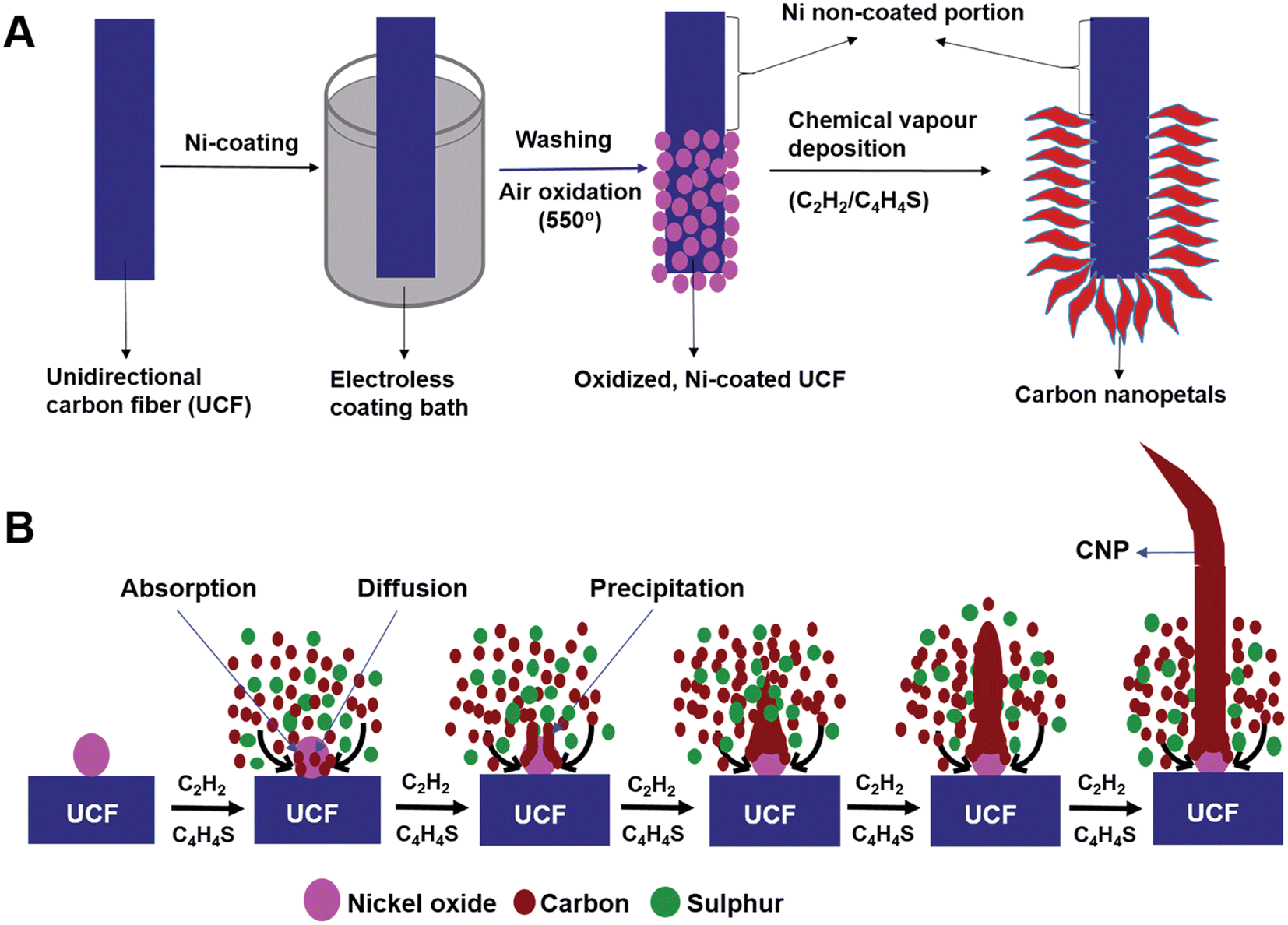
A novel carbon nanostructure termed carbon nanopetals (CNPs) was reported in the literature.58 The CNPs were grown on a unidirectional CF (UCF) via the CVD method and further used as a flexible electrode for SC application. The CNP/UCF hybrid material was further used as electrode-cum-current collector for the fabrication of a flexible SC. For the synthesis of CNPs, initially nickel was coated on UCF via the electroless coating method. The electroless coating bath contained nickel sulphate hexahydrate, sodium hypophosphate, ammonium chloride, trisodium citrate and liquor ammonia. Firstly, UCF was dipped in the electroless coating bath at a fixed temperature of 85 °C under constant stirring for a duration of 10 min, followed by rinsing it several times using ethanol and de-ionized water, and subsequently dried at 85 °C for 24 h. The UCF strands coated with nickel nanoparticles were further oxidized at a temperature of 550 °C in an air-bed reactor for 30 min to form nickel oxide nanoparticles. The proposed oxidized nickel-coated UCF acted as a substrate to synthesize CNPs using catalytic CVD. During this process, the oxidized, nickel-coated UCF was heated to a temperature of 500 °C in a horizontal quartz furnace under a continuous flow of N2. To avoid the excess generation of oxides on nickel nanoparticles, H2 was introduced at a flow rate of 100 mL min−1 for a duration of 15 min. Subsequently, the temperature was increased to 700 °C and acetylene gas introduced at a flow rate of 90 mL min−1 for 15 min, keeping the N2 flow fixed at a rate of 200 mL min−1. Later, thiophene was introduced inside the CVD reactor simultaneously by heating a round-bottom flask kept at a temperature of 80 °C in the route of N2 flow. The CNPs grown on UCF were collected after cooling the CVD reactor to room temperature under an N2 flow. The entire procedure for the synthesis of CNPs over UCF is shown in Fig. 17A. The proposed mechanism for the growth of CNPs on UCF is depicted in Fig. 17B. The CVD growth established for CNPs involved four sequential procedures, including the transportation of mass and reaction in the gas phase, dissociative absorption of carbon atoms on the surface of the nickel oxide nanoparticles, carbon atom diffusion on their surface and carbon atom precipitation from the nickel oxide nanoparticles.
 | ||
| Fig. 17 (A) Pictorial representation of procedures involved in the synthesis of CNPs on UCF and (B) mechanism of growth of CNPs on UCF. Reproduced with permission from ref. 58 Copyright (2016), The Royal Society of Chemistry. | ||
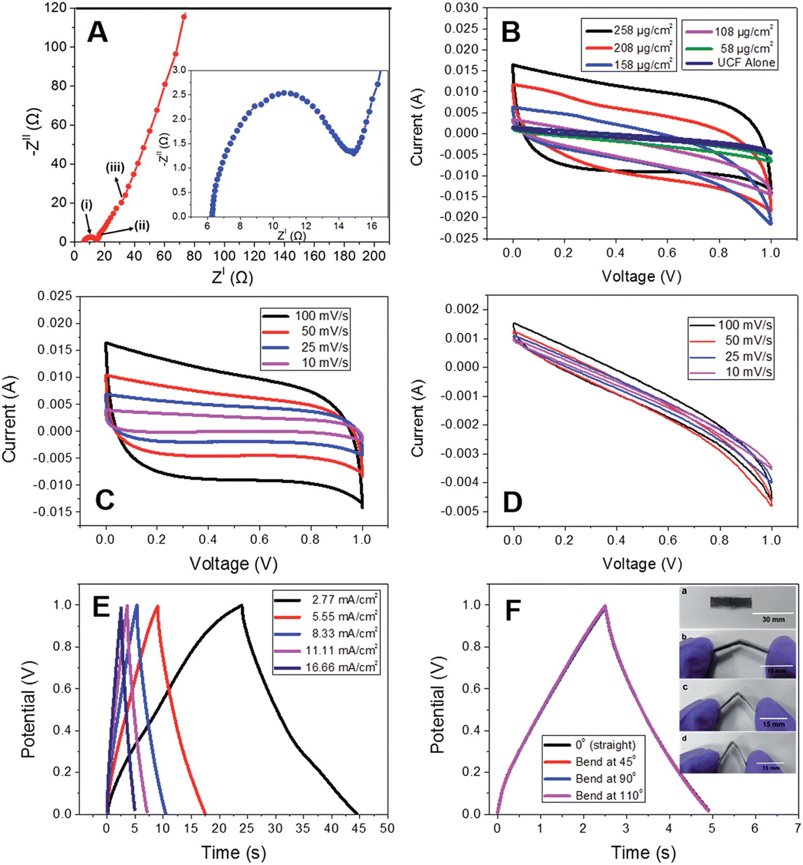
The CNPs grown on UCF were further used as an electrode-active material for fabricating a SC. According to the Nyquist plot (Fig. 18A), it was found that the SC exhibited a bulk electrolyte resistance of about 6.2 Ω, and this small resistance value indicates that the electrode-active material possessed high ionic conductivity. The CV curves were measured with a variation in the loading content of carbon nanopetals (258, 208, 158, 108, and 58 μg cm−2) for the hybrid SC electrode (Fig. 18B). The CV curves exhibited by CNP/UCF SC with the electrode having a CNP loading density of 258 μg cm−2 at different scan rates are shown in Fig. 18C. The CV curves possess a near-rectangular shape, representing the efficient double layer charge storage mechanism in accordance with the efficient propagation of charges through the electrode-cum-current collector. To examine the electrochemical characteristics of the pristine UCF SC electrode-active material, the CV analysis was performed in a two-electrode cell configuration at different scan rates, as presented in Fig. 18D. According to this analysis, it is clear that there was only a slight contribution to the charge storage from the pristine UCF. The GCD analysis of the CNP/UCF SC electrode with respect to different current densities is presented in Fig. 18E. According to this analysis, it is clear that the SC possesses a high discharge capacitance of 102.6 mF at a current density of 2.77 mA cm−2 and 69.9 mF at a comparatively high current density of 11.11 mA cm−2. The porous architecture of the SC electrode together with the CNP orientation facilitated the rapid movement of the electrolyte-ions, thereby resulting in accelerated charge transfer, which led to a high-performance. To demonstrate the practical applicability of CNP/SC in flexible electronic devices, the SC was subjected to a bending test, in which the CNP/UCF SC was bent at different bending angles (Fig. 18F). The GCD curves obtained for the SC at different bending angles such as 0°, 45°, 90°, and 110° are depicted in Fig. 18F. The bending test displayed no significant variation in the charge/discharge profiles, which represents the excellent flexibility of the SC. An areal capacitance of 39.8 mF cm−2 was obtained at 0° and it was found to be unaltered even upon severe bending at 180°. By increasing the loading of CNP, the CV curve exhibited a large area under the curves, which was reduced with a decrease in the CNP content in the electrode. The volume specific energy density obtained for the CNF/UCP SC is 0.753 mW h cm−3 with a corresponding gravimetric energy density of 30 W h kg−1 at a constant current density of 2.77 mA cm−2.
 | ||
| Fig. 18 (A) Nyquist plot (inset represents Nyquist plot in high frequency region); (B) CV curves at different loading densities; (C) CV curves for different scan rates for the CNP loading density of 258 μg cm−2 of CNP/UCF SC; (D) CV curves of UCF at various scan rates. GCD curves at (E) various current densities and (F) various bending angles of CNP/UCF SC (inset shows the digital photograph of CNP/UCF SC bent for 0° (a), 45° (b), 90° (c), and 110° (d)). Reproduced with permission from ref. 58 Copyright (2016), The Royal Society of Chemistry. | ||
Carbon-based flexible SCs are promising candidates for powering smart textile wearable electronics. However, their low energy density hinders their industrial applications, especially due to the lack of efficient approaches for the synthesis of highly conductive fiber electrodes exhibiting a high specific capacitance. Hu et al.59 developed a sustainable, cost-effective approach in a scalable way to develop a lignin-based carbon/graphene fiber (CG@GF) hybrid with a porous structure and further used it as an electrode-active material for SC. This environment-friendly approach can enable the large-scale preparation of CG@GF hybrids for a variety of applications including SC electrode preparation. A schematic representation of the CG@GF hybrid depicting its overall synthesis procedure and the CG@GF SC is presented in Fig. 19. Here, the lignin powder was firstly dissolved in 5 mL aqueous KOH solution by fixing the KOH to lignin mass ratio at 2:1. KOH was added to the lignin solution to introduce the dissolution of lignin in an alkaline environment and create a homogeneously arranged spinning dope. With 0% lignin, the solvent was water without any KOH. The as-prepared alkaline solution was added dropwise to the GO solution and its concentration was fixed to be 15 mg mL−1. Later, the CG@GF hybrid fibers were synthesized via the coaxial wet spinning method.
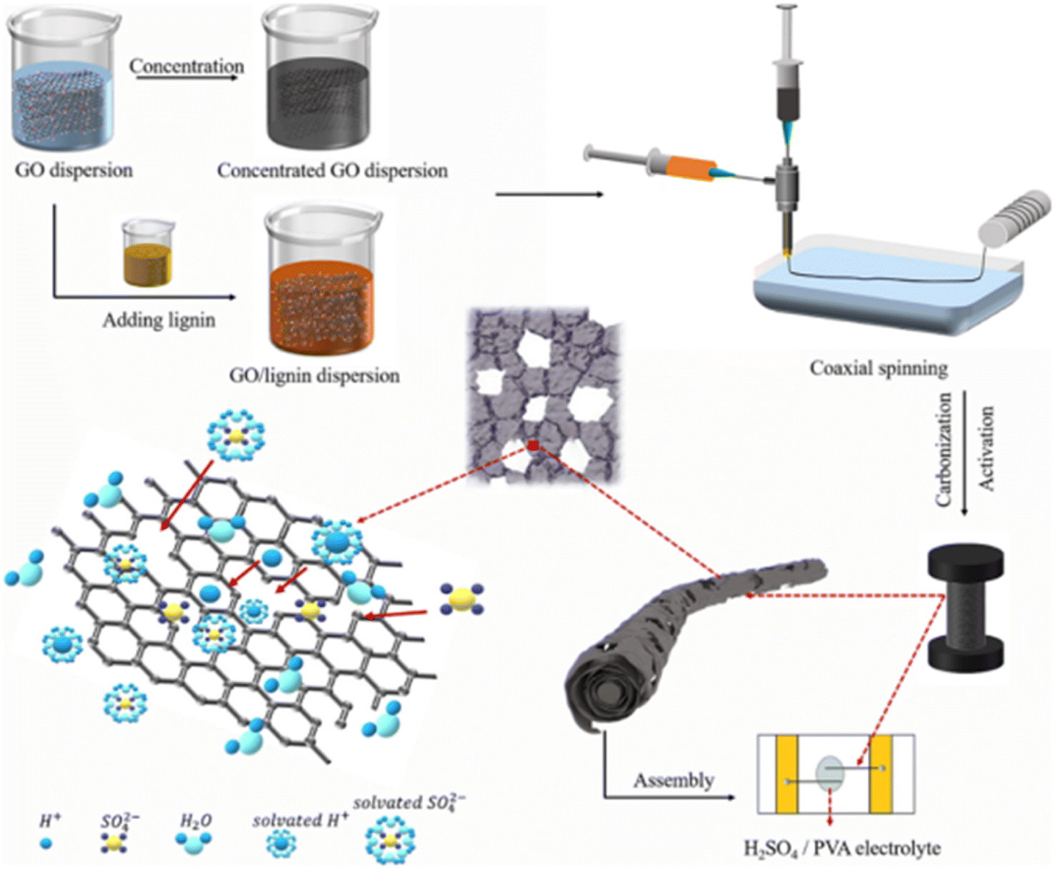 | ||
| Fig. 19 Pictorial representation of the procedure for the synthesis of CG@GF electrode and fabrication of flexible SC. Reproduced with permission from ref. 59 Copyright (2021), the American Chemical Society. | ||
The significance of carbon with lignin in the electrochemical performance of the CG@GF SC electrode was evaluated by CV measurement, as shown in Fig. 20a. It can be observed from the CV curves that the CG@GF SC electrode exhibited a rectangular curve with a rapid propagation of charges at a scan rate of 5 mV s−1. Also, the coaxially wet spun fiber in a ratio of 0% CG@GF possessed a smaller area due to the increase in the fiber diameter. The GCD curves of the CG@GF hybrid-based fiber SC electrode (Fig. 20b) show an almost symmetric isosceles with a triangular-shaped correlation between the time and charge/discharge potential at a current density of 0.1 mA cm−2 in the potential window of 0–0.8 V. These features indicate that the CG@GF hybrid-based fiber SC electrode possessed efficient charge/discharge characteristics. The area specific capacitance of the CG@GF hybrid-based fiber SC electrode calculated from GCD curve is shown in Fig. 20c. The pure graphene fiber electrode exhibited an area specific capacitance of 23.9 mF cm−2 at a current density of 0.1 mA cm−2. It was also observed that with an increase in the current density from 0.1 to 1 mA cm−2, the wet-spun coaxial carbon-based fibers exhibited the capacitance retention of 60%, 57%, 65%, and 49% for the 0%, 3%, 5%, and 10% CG@GF hybrid electrodes, respectively. The Nyquist plots show that (Fig. 20d) the wet spun fibers exhibited a large semi-circle in the high-frequency region, depicting a high charge transfer resistance.
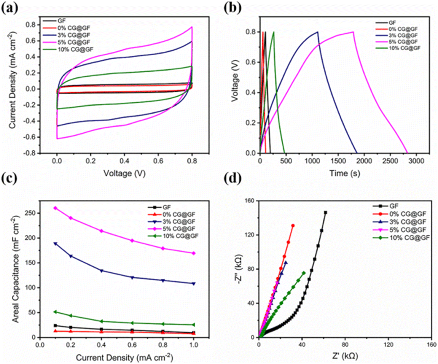 | ||
| Fig. 20 (a) CV curves at scan rate of 5 mV s−1; (b) GCD curves at a current density 0.1 mA cm−2; (c) area specific capacitance obtained from the GCD curves at different current densities; and (d) Nyquist plots of flexible SC. Reproduced with permission from ref. 59 Copyright (2021), the American Chemical Society. | ||
4.2 Carbon fibers/layered double hydroxide nanocomposite electrodes
Layered double hydroxides are excellent candidates for SC electrode application due to their pseudocapacitive charge storage. Layered nanostructured electrodes facilitate the diffusion of the electrolyte-ions, thereby achieving enhanced charge storage. Gao et al.60 fabricated a flexible SC with nickel–cobalt double hydroxide (Ni–Co LDHS) using pen ink electrodes constructed using a CF substrate. The fabrication of a solid-state asymmetric SC using these electrodes is depicted in Fig. 21a. Here, a CF thread possessing small diameter in the range of 200–400 μm was selected as the primary electrode due to its appropriate stiffness, light weight and good conductivity. The electrical conductivity of the CF thread was enhanced when it was coated with a thin layer of nickel via the electrodeposition technique. The resultant electrode possessed enhanced conductivity compared to that of the pristine CF, as evident in Fig. 21b, which increased by a factor of 3.3 and found to be lighter than the corresponding pure metal yarns. This was attributed to the deposition of a thin nickel layer (about 820 nm), which enhanced the mass of the electrode. Also, a reduction in the tensile strength of the fabricated SC electrode from 2.05 to 1.47 GPa was observed, which is mainly due to the adverse effect introduced by the interaction of the surface carbon filament and deposited nickel atoms, and the tensile test results are shown in Fig. 21c.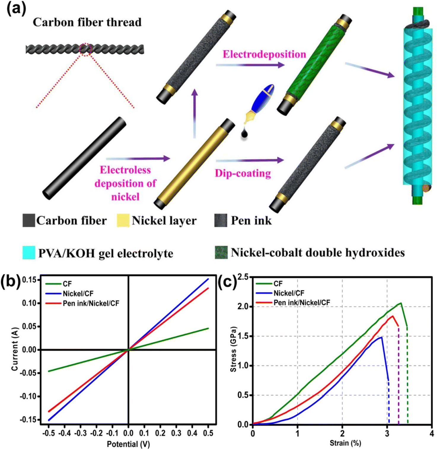 | ||
| Fig. 21 (a) Pictorial representation of the process for the fabrication of flexible fiber-type solid-state asymmetric device and its (b) conductivity measured in two-electrode test and (c) analysis of tensile properties. Reproduced with permission from ref. 60 Copyright (2017), the American Chemical Society. | ||
The surface morphology of the fabricated hierarchical fiber electrodes is shown in Fig. 22. A single CF filament with a thickness of 6.93 μm possessing a smooth surface can be viewed in Fig. 22a and this CF filament coated with a thin nickel layer having a thickness of 820 nm are shown in Fig. 22b. Because of the effective chemical penetration towards the core of CF, nickel was uniformly deposited on the CF thread bundle, as shown in Fig. 22c. Fig. 22d and e confirm the uniform distribution of the pen ink on the nickel/CF thread. The enlarged view of the pen ink film (Fig. 22f) shows a porous structure possessing a ravine morphology, which was beneficial for enhancing the surface area of the electrode nanostructure, thereby enhancing the electrochemical reactions. The FESEM image corresponding to Ni–Co LDHS on the substrate is shown in Fig. 22g. In Fig. 22h, it can be found that a thin transparent interconnected network grew on the ink film, which created a highly electrically conducting network consisting of numerous electroactive surface regions for enhanced electrochemical reactions to occur. The nanosheet microstructure having a rippled silk-like morphology was observed in the high-magnification SEM image, as depicted in Fig. 22i.
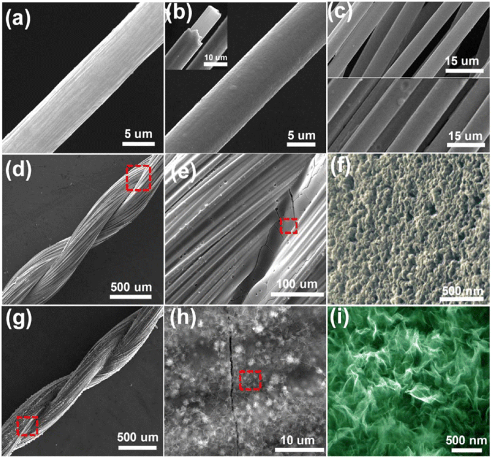 | ||
| Fig. 22 SEM images corresponding to (a) CF with a smooth surface; (b) CF uniformly coated on nickel layer having a smooth surface; (c) top portion of CF bundle and bottom portion is the CF bundle, which was coated using nickel; (d and e) nickel/CF coated with pen ink film; (f) porous structure with ravine morphology of pen ink/nickel/CF; (g and h) Ni–Co LDHS creating a uniform conductive network with ink film having porous nature and (i) SEM image at higher magnification. Reproduced with permission from ref. 60 Copyright (2017), the American Chemical Society. | ||
An asymmetric SC was fabricated using the Ni–Co LDHS as the positive electrode and ink-coated nickel/CF as the negative electrode. The CV curves of the as-fabricated asymmetric SC in the potential window of 0–0.8 V to 0–1.55 V are presented in Fig. 23a. The area under the curve was found to obviously increase upon widening the potential window. The GCD curves of the as-fabricated asymmetric SC in the potential window of 0–0.8 V to 0–1.55 V are presented in Fig. 23b and it can be seen that the SC functioned in the stable potential window of 0–1.55 V without any significant potential drop. The CV curves of the as-fabricated asymmetric SC at different scan rates such as 5 mV s−1, 10, 20, 40, 60, 80, 100, and 150 mV s−1 in the potential window of 0–1.55 V are depicted in Fig. 23c, showing that the redox-active electrodes had efficient reaction kinetics. The GCD curves of the as-fabricated asymmetric SC at different current densities are shown in Fig. 23d, which indicate a hybrid charge storage mechanism. The specific capacitance of the SC was found to be 22.94 F g−1 at a current density of 0.5 A g−1, which decreased to 7.9 F g−1 when the current density changed to 2 A g−1. A high capacitance retention of 86% was also observed for the SC during the cyclic study even after 5000 cycles (Fig. 23e). The GCD curves in the initial cycle and after completing the cycling study are depicted in the inset of Fig. 23e. The variation in energy density and power density of the SC in the form of Ragone plot is presented in Fig. 23f (optical images of device are shown as inset). According to this plot, it can be seen that with an increase in the current density from 0.5 to 2 A g−1, a reduction in the specific energy density occurred from 7.66 W h kg−1 to 3 W h kg−1.
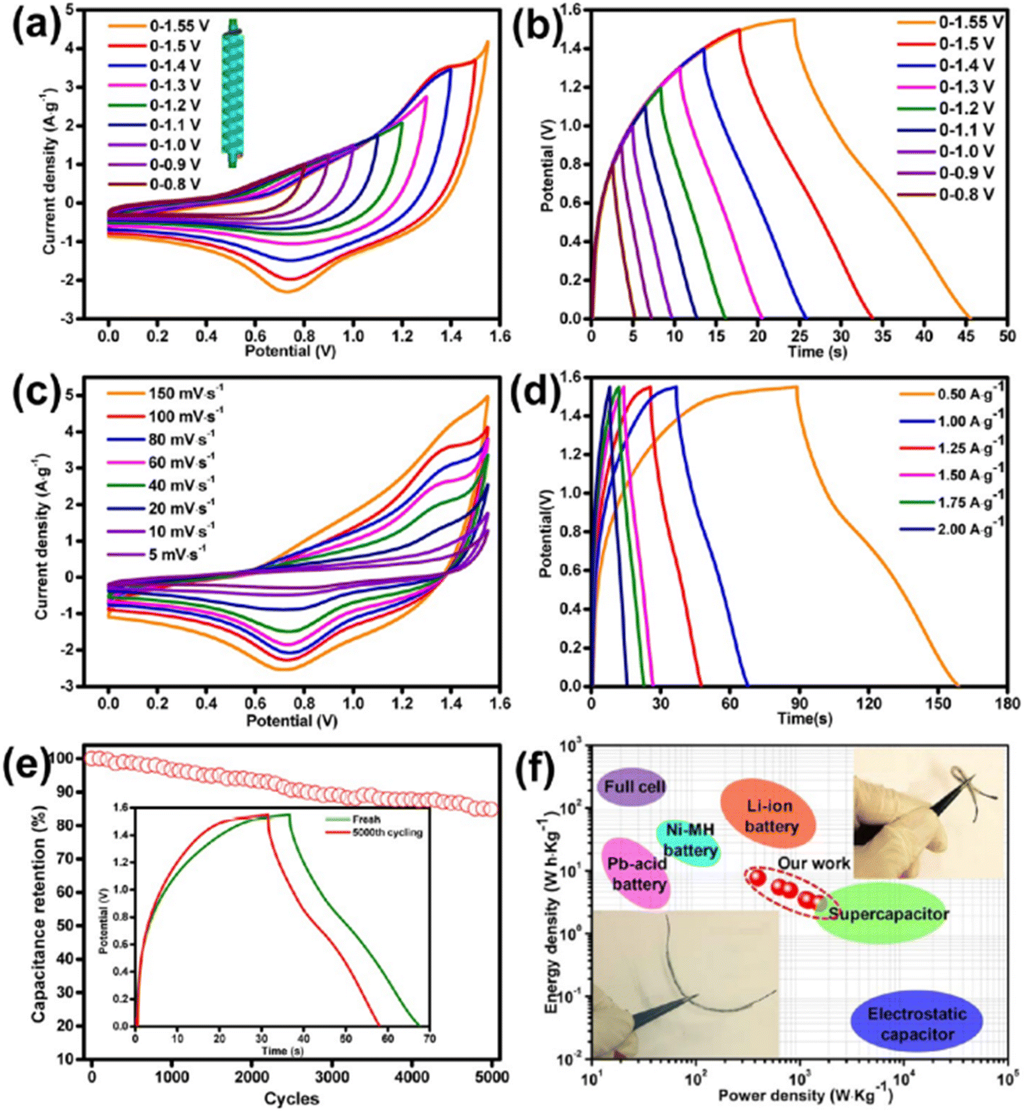 | ||
| Fig. 23 Electrochemical studies of fabricated asymmetric SC in KOH/PVA gel electrolyte: (a) CV curve at 100 mV s−1 scan rate; (b) GCD curve in various voltage windows at a fixed current density of 1.25 A g−1; (c) CV curve at scan rate of 5–150 mV s−1; (d) GCD curve at the current density of f 0.5–2.0 A g−1; (e) cyclic stability analysis of the device at a current density of 1 A g−1 with the inset representing the GCD curves of the device before and after 5000 cycles; and (f) Ragone plot, inset corresponding to the optical image of device. Reproduced with permission from ref. 60 Copyright (2017), the American Chemical Society. | ||
A solvothermal reaction was employed to synthesize Ni–Co LDHS nanosheets on CF cloth by Wang et al.61 By using a 2-methylimidazole complex and methanol as the solvent, an LDHS nanosheet layer was prepared on CF, which exhibited growth in the (003) direction with an expansion of the interlayer spaces. This resulted in the formation of a 3D porous structure having a thickness of 5–7 nm. A pictorial representation of the charge storage mechanism of the SC electrode is shown in Fig. 24.
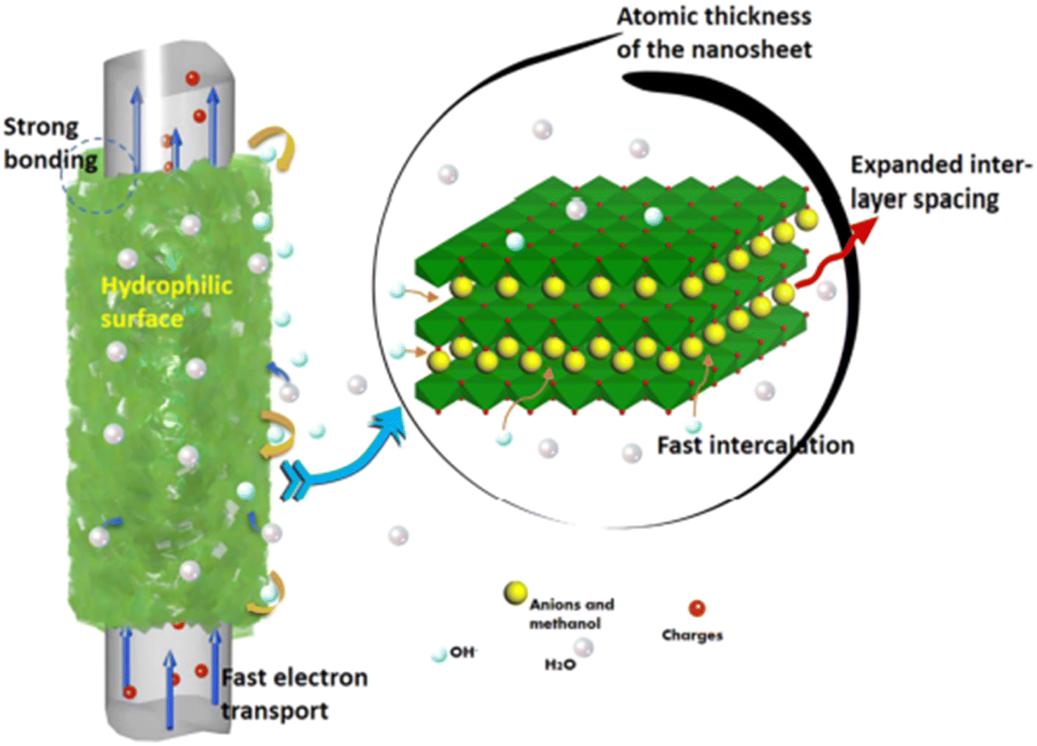 | ||
| Fig. 24 Diagrammatic representation of the charge storage mechanism in the electrode material. Reproduced with permission from ref. 61 Copyright (2017), the American Chemical Society. | ||
A SC was fabricated using the Ni–Co LDHS as the positive electrode and carbon nanorod as the negative electrode. The CV curves of the as-fabricated SC in the potential window of 0–0.8 V to 0–1.6 V are presented in Fig. 25a. The SC could work in the potential window of 0–1.6 V without any deterioration in its behavior but the authors selected a slightly lower potential window of 0–1.4 V. The CV curves of the as-fabricated SC at different scan rates in the potential window of 0–1.4 V are presented in Fig. 25b. The specific capacitance of the SC was calculated at different scan rates and plotted in Fig. 25c. A maximum capacitance of 317.9 mF cm−2 was obtained for the SC at a lower scan rate of 2 mV s−1, which was found to decrease exponentially at higher scan rates. The Nyquist plot of the SC shown in Fig. 25d shows the Nyquist plot of the SC with an equivalent circuit model and a series resistance of 10.15 Ω cm−2 with a charge transfer resistance of 0.71 Ω cm−2 was obtained, which represents its excellent conductivity. The as-fabricated SC was found to be highly flexible when the bending test was carried at different bending angles. The CV curves obtained at different bending angles from 15° to 180° showed no significant variation, indicating its excellent flexibility. Jagadale et al.62 reported the synthesis of CoAl LDHS on CF yarns using the electrodeposition approach, which were employed as electrode-active materials for the fabrication of a solid-state SC. The solid-state SC was fabricated using CoAl LDHS on CF yarns as the electrode and KOH–PVA gel electrolyte. The electrochemical performance of the solid-state SC was tested and an area specific capacitance of about 195 mF cm−2 and a volumetric energy density of 1.6 mW h cm−3 were obtained.
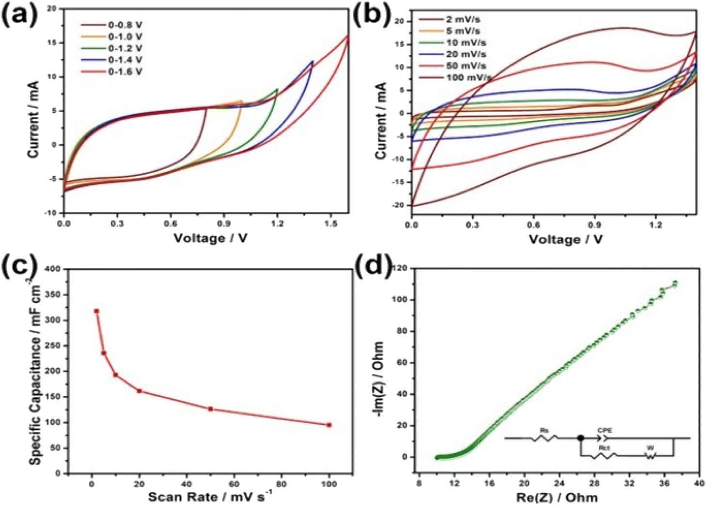 | ||
| Fig. 25 (a) CV curves of the device at various voltage windows at a sweep rate 20 mV s−1; (b) CV curves; (c) specific capacitance at various sweep rates; and (d) EIS spectrum. Reproduced with permission from ref. 61 Copyright (2017), the American Chemical Society. | ||
4.3 Carbon fiber/carbon nanostructure nanocomposite electrodes
Carbon–carbon nanocomposites are highly demanded for SC electrode application due to their good electronic conductivity, high chemical and electrochemical stability, easy synthesis, etc. Carbon nanostructures such as CNTs, graphene, and CNPs have been highly exploited as electrode-active materials for SC application recently. However, graphene-based SC electrodes exhibit the disadvantage of the restacking of the graphene layers during their preparation. This leads to the closure of the available pores in the electrode nanostructure, which eventually deteriorates its electrochemical performance. Thus, to avoid the restacking of the layers of graphene when it is employed as an electrode-active material for the fabrication of SCs, a new strategy was reported to align the graphene sheets vertically on a CF substrate.32 This novel strategy was found to be a versatile method for the preparation of graphene electrodes by the vertical attachment of graphene sheets to CF (VGCF), and thereby the specific surface area of graphene available for electrochemical reactions to occur is enhanced. The VGCF hybrid electrode was synthesised via electrophoretic deposition, as shown in Fig. 26a–c, where CF having an average diameter of 6 μm was applied as the substrate for depositing graphene sheets. Electrophoretic deposition was performed, whereby the graphene sheets, which were positively charged due to the adsorption of nickel ions, were transported towards CF electrode. The electrophoretic deposition of graphene sheets was performed by applying a DC potential of 50 V (Fig. 26b), producing a 3D VGCF hybrid electrode (Fig. 26c). The electron transport in the VGCF hybrid SC electrode is schematically presented in Fig. 26d.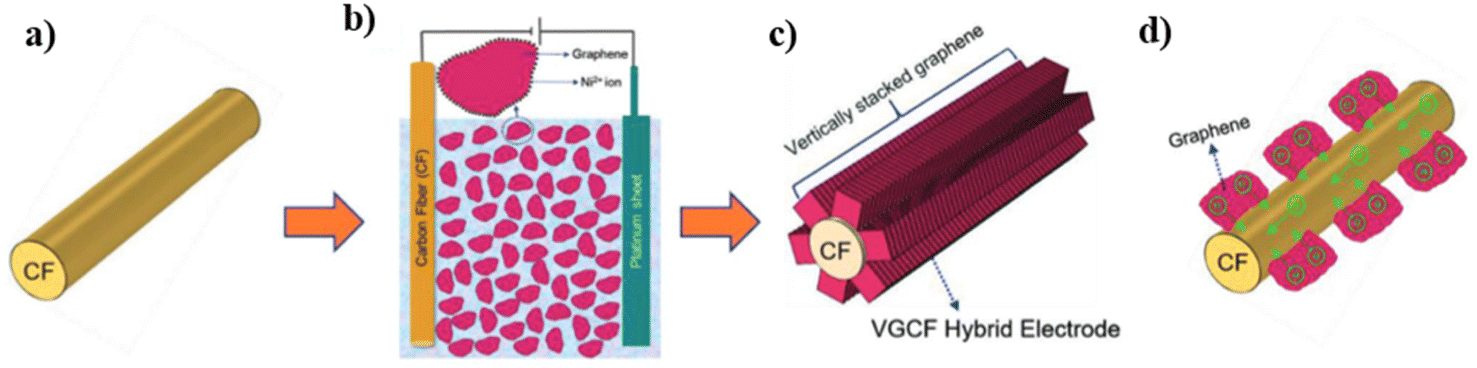 | ||
| Fig. 26 Pictorial representation of the synthesis of the VGCF electrode: (a) CF substrate for electrophoretic deposition; (b) electrophoretic deposition with CF as the negative electrode, Pt as the positive electrode, and a bath consisting of a dispersion of graphene sheets in isopropyl alcohol with nickel nitrate hexahydrate; (c) VGF hybrid after electrodeposition; and (d) pictorial representation of electron transport from graphene to CF. Reproduced with permission from ref. 32 Copyright (2019), WILEY-VCH Verlag GmbH & Co. KGaA, Weinheim. | ||
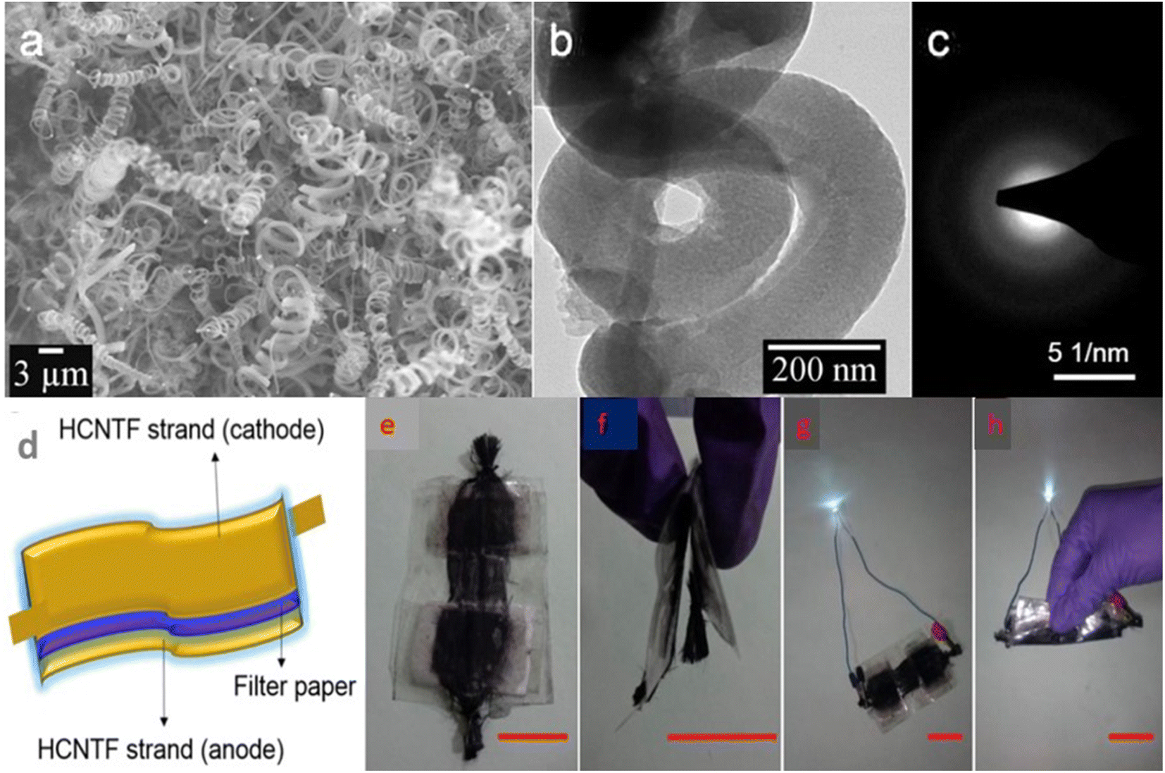
To analyse the application of this VGCF hybrid electrode material for industrial purposes, the authors fabricated a symmetric SC using 1 M aqueous H3PO4 as the electrolyte. The Nyquist plot of the VGCF hybrid electrode is shown in Fig. 27a and the Nyquist plot in the high-frequency region is shown as an inset image, which showed that the electrode exhibited a low electrolyte series resistance. The CV curves obtained for the VGCF hybrid SC (Fig. 27b) showed that the hybrid electrode exhibited redox-type charge storage induced by the presence of oxygen-containing surface functional groups on the graphene sheet and α-Ni(OH)2. The charge storage contribution from the surface-controlled and the diffusion-controlled mechanism was calculated by using Dunn's method, showing that the electrode material has 70% surface-controlled and 30% diffusion-controlled charge storage, as depicted in Fig. 27c. The GCD curves obtained for the VGCF hybrid SC, as shown in Fig. 27d, exhibited a charge/discharge profile with two slopes, which is due to the different charge storage mechanisms introduced by the electrode. The CV study performed in the potential window of 0–1.6 V (Fig. 27e) depicted the efficient charge storage capability of the SC. The VGCF hybrid SC exhibited a capacitance retention of 99.4% even after 17000 cycles (Fig. 27f) and the inset image shows the CV curves where no significant change in the area under the curve in the first cycle and the last cycle were observed. The flexibility of the SC was analysed by bending it at different bending angles such as 30°, 45°, 60°, 90°, 135°, and 180° and the CV curves obtained are shown in the inset of Fig. 27g. According to these CV curves, it is clear that the SC device exhibited a capacitance retention of 100% even under severe bending at 180° (Fig. 27g). The SC was found to retain its capacitance even after completing 1000 bending cycles (Fig. 27h). The inset image of Fig. 27h is the digital photograph taken at a bending angle of 90°. The device prototype of the fabricated SC, which operated a toy drone propeller fan, is shown in Fig. 27i and the running of the fan is shown as an inset image. In another study, free-standing helically coiled CNTs (HCNTs) grown on CF (HCNTF) were used as an electrode-cum-current collector for the fabrication of a flexible SC.63 The authors synthesized the HCNTF hybrid via the CVD method using thiophene as the defect-induced catalyst for the growth of HCNTF. The flexibility of this SC was analysed by subjecting it to bending angles of 0°, 30°, 60°, 90°, and 120°. The rate performance of the fabricated electrode with an HCNT density of 5.77 mg cm−3 was verified by GCD measurements performed at various current densities. It is worth noting that the HCNTF hybrid electrode could be charged at a relatively higher current density of 8.33 mA cm−2. A solid-state SC was fabricated by using the HCNTF hybrid electrode-cum-current collector and PVA/LiCl gel electrolyte. The SEM image (Fig. 28a) shows a mesoporous open network of HCNTs. The TEM image of a single strand of HCNT is depicted in Fig. 28b. The SAED pattern (Fig. 28c) shows that HCNT was not crystalline due to its defect-induced growth. A schematic representation of the fabricated solid-state SC is shown in Fig. 28d. A digital image of the SC module comprised of two similar solid-state HCNTF SCs connected in series is shown in Fig. 28e and this module bent at an angle of 180° is shown in Fig. 28f. The practical application of this SC module in wearable electronic devices was demonstrated by lighting an LED at its normal position (Fig. 28g) and at a severe bend of 180° (Fig. 28h)), which showed no change in the light intensity.
 | ||
| Fig. 27 Electrochemical analysis of VGCF SC: (a) Nyquist plot (high-resolution view of high-frequency region); (b) CV at different scan rates; (c) calculation of contribution of capacitance at a scan rate of 25 mV s−1; (d) GCD curves at various current densities; (e) CV at various scan rates; (f) capacitance retention with cycle number for 17000 cycles; (g) capacitance retention at various bending angles (inset is the CV at various bending angle at 100 mV s−1 scan rate); (h) capacitance retention at 1000 bending cycles (inset is the digital photograph at an angle of 90°); and (i) device prototype. Reproduced with permission from ref. 32 Copyright (2019), WILEY-VCH Verlag GmbH & Co. KGaA, Weinheim. | ||
 | ||
| Fig. 28 (a) SEM; (b)TEM; and (c) SAED images of HCNTF having an HCNT density of 5.77 mg cm−3; (d) pictorial representation of fabricated device; (e) series connection of two solid state flexible HCNTFs; (f) bending of module at 180°; (g) discharging of module by LED; and (h) discharging of module by a white LED with bending at 180°. Reproduced with permission from ref. 63 Copyright (2016), Elsevier. | ||
Yang et al.64 developed a sandwich patterned reduced graphene oxide (rGO)/carboxylated multi-walled CNT (MWCNT) (RGO/cMWCNT) hybrid film and polypyrrole supported with CF paper (CFP/PPy) using a vacuum infiltration method and electrochemical deposition. An asymmetric SC was fabricated using RGO/cMWCNT as the negative electrode, CFP/PPy as the positive electrode, and potassium polyacrylate/KCl gel electrolyte. This asymmetric SC exhibited an energy density of 28.6 W h kg−1 at the corresponding power density of 15.1 kW kg−1 and working cell voltage of 1.6 V. Also, this device maintained a capacitance retention of 93% with a long cycle life after 2000 cycles. Using a two-step solution process involving hydrothermal and chemical bath deposition, Liu et al.65 synthesized an SnO2@MOx heterostructure on CF cloth to fabricate a high-performance SC. This heterostructure possessed the features of good electronic conductivity of the SnO2 nanosheets as the backbone for the deposition of MOx. The as-fabricated SC showed a high discharge area specific capacitance of 980 mF cm−2 at a current density of 1 mA cm−2 together with an efficient rate capability of about 767 mF cm−2 when tested at a comparatively higher current density of 20 mA cm−2. The SC exhibited efficient cyclic stability of ∼21.9% retention after completing 6000 cycles at a current density of 1 mA cm−2. Lu et al.66 synthesized MnO2 tube-in-tube arrays supported on CF cloth using a facile template-assisted electrodeposition route. The solid-state SC fabricated with PVA/LiCl showed a high area specific capacitance of about 322 mF cm−2 at a current density of 0.125 A g−1. This SC exhibited a volumetric energy density of 0.073 mW h cm−3 at the corresponding power density of 25 W kg−1 together with a capacitance retention of 96.4% even after completing 2000 cycles. An asymmetric fiber-shaped SC in a weavable and flexible pattern using CF bundle@CNT-NiCo(OH)x (CF@CNC) as the positive electrode and CF bundle@activated carbon (CF@AC) as the negative electrode was reported by Lu et al.67 To overcome its disadvantages of hydrophobic nature, reduced electrical conductivity and low surface area, treatment with air plasma and modification with CNT were performed during the fabrication of CF@CNC. This asymmetric SC exhibited an energy density of 0.84 mW h cm−3 at the corresponding power density of 19.1 mW cm−3. A high capacitance retention of 100% was also observed even after completing 8000 charge/discharge cycles. Using electrospinning and carbonization process on a CNF membrane, a flexible polypyrrolone/polyimide composite (PBPICF) was prepared by Liu et al.68 For the preparation of PBPICF, polycarboxylic acid ammonium salt (PCAAS) and polyamic acid (PAA) were mixed in different proportions. The prepared nanofibers exhibited a network structure, having a uniform diameter of about 400–500 nm. The prepared PBPICF membrane exhibited efficient flexibility and could be bent and folded without breaking. This report showed that the prepared SC exhibited a specific capacitance of 172.44 F g−1 at a current density of 0.2 A g−1. These results show that this binder-free, flexible membrane can be employed for the fabrication of SCs with a good performance. Here, the prepared PBPICF membrane exhibited an efficient power density value of 90 W kg−1 at 19.4 W h kg−1 energy density with a capacitance retention of 96% after 10000 cycles at a current density of 1 A g−1.
With the aid of a multi-step transformation procedure, Tong et al.69 fabricated elm-seed-structured NiS2 nanosheets on the surface of coal-based CF. Here, the silica/coal-based fiber was prepared by electrospinning a mixed solution consisting of oxidized coal, polyvinyl alcohol and tetraethyl orthosilicate in water/N,N-dimethylformamide, followed by carbonization. Due to its large surface area and novel structure, the as-prepared binder-free hybrid electrode was employed for the fabrication of an SC, which exhibited a high specific capacitance of about 635.1 F g−1 at a current density of 1 A g−1. Also, the SC electrode showed a capacitance retention of about 96.4% after 5000 cycles. Ding et al.70 fabricated a fiber electrode, where acidified CF was modified by rGO/g-C3N4. The symmetric SC fabricated using this electrode exhibited an areal capacitance of 61 mF cm−2 with a capacitive retention of 90% after 5000 cycles. Using hydrothermal approach, Yu et al.71 created a 3D nanostructure by combining a vertical polyaniline (PANI) nanowire array and nitrogen plasma etched-carbon fiber cloth (eCFCs) as an electrode for flexible SC. The flexible SC showed a high specific capacitance of 1035 F g−1 at a current density of 1 A g−1. It possessed an efficient capacitance retention of 88% even at a comparatively higher current density of 8 A g−1 with a long cyclic stability of 5000 cycles. The flexibility of the assembled PANI/eCFC was evaluated under fixed mechanical stress and its performance was evaluated. They observed that this assembled device has efficient flexibility and mechanical properties and could be bent at different angles. The proposed performance durability is related to the higher mechanical flexibility of the electrode and the strong connection between the nitrogen-doped eCFC and PANI arrays, indicating their application in flexible electronics.
4.4 Carbon fiber-based wired electrodes
Wired SCs have exhibited tremendous potential in the current era due to their rapid discharge capacity, flexibility, weavable structure, long cycle life and easy integration with on-body wearable electronic devices. Ai et al.72 fabricated a solid-state wired SC using a nanostructured CoNiO2@CF nanocomposite electrode and activated carbon@CF electrode having length greater than 1 m. A schematic representation of the fabrication of this asymmetric solid-state SC is shown in Fig. 29. Here, the anode and cathode fiber are twisted on a polymethylmethacrylate (PMMA) backbone using KOH–PVA gel electrolyte and PDMS layer as shell. The as-fabricated asymmetric SC exhibited efficient flexibility, wearability and toughness. | ||
| Fig. 29 Pictorial representation of the process for the fabrication of wired asymmetric SC. Reproduced with permission from ref. 72 Copyright (2016), WILEY-VCH Verlag GmbH & Co. KGaA, Weinheim. | ||
The electrochemical characteristics of the asymmetric SC were analysed using a 10 nm length, as shown in Fig. 30a. The CV measurements were carried out in the potential window of 0–1.8 V and the CV curves (Fig. 30b) obtained at different scan rates from 5 mV s−1 to 500 mV s−1 showed a quasi-rectangular nature. The discharge curves of the asymmetric SC in the potential window of 0–1.8 V are shown in Fig. 30c. The specific capacitances calculated from the discharge curves are 16.75, 16.55, 16.14, 15.91, 15.45, 14.95, 14.41, 13.89, 13.32, and 10.24 mF at the current densities of 0.5, 1, 1.5, 2, 2.5, 3, 3.5, 4, 4.5, and 5 mA, respectively (Fig. 30d). The wire-shaped SC exhibited an energy density of 0.95 mW h cm−3 at the power density of 1.14 mW cm−3 (Fig. 30e) and possessed a capacitance retention of about 97% after completing 5000 cycles (Fig. 30f). The mean variation tendency for capacitance exhibited by the wired asymmetric SC is shown in Fig. 30g.
 | ||
| Fig. 30 (a) Digital image of asymmetric wired SC with a length of 1.2 m; (b) CV and (c) GCD curves of SC device; (d) comparison of the capacitance of spiral double-helix twisted asymmetric wire supercapacitor with that of the straight twisted asymmetric wire supercapacitor; (e) Ragone plot; (f) cyclic stability analysis; (g) change in capacitance of device with length measured under similar conditions. Reproduced with permission from ref. 72 Copyright (2016), WILEY-VCH Verlag GmbH & Co. KGaA, Weinheim. | ||
Harvesting wind power in association with SCs has received great attention due to their sustainable energy conversion and storage features. The energy obtained from wind turbines can be easily stored in an SC but a major requirement for this is that the SC should exhibit a high energy density. However, the fabrication of SCs with a high energy density and reduced internal resistance is a tedious task. Shi et al.73 developed a strategy to merge a wind-driven generator (WDG) with an asymmetric wire-shaped SC (WSSC), where the WDG part was responsible for the conversion of energy and the asymmetric WSSC was responsible for storing the energy. The asymmetric WSSC was assembled using CoNi2S4 nanosheet arrays and vertical FeOOH coated on flexible CF tubes (CFTs) as the negative and positive yarn electrode, respectively (Fig. 31a). Here, the vertically aligned cross-linked porous network was introduced by the electroactive nanosheet array was found to be suitable for the diffusion of ions and transportation of charges. Fig. 31b and c present the FESEM images of the FeOOH/CFTs yarn electrode at different magnifications. Here, it can be observed that the CFTs were fully covered by FeOOH (Fig. 31b). In the case of the high-magnification FESEM image (inset image of Fig. 31c), it can be seen that a vertically aligned FeOOH nanosheet with an average thickness in the range of 20 nm was obtained. These nanosheets tended to interconnect to without producing any agglomeration effect. In the case of the CoNi2S4/CFTs yarn electrode, a network architecture over CFT was introduced by the uniform construction of CoNi2S4 nanosheet vertical arrays (Fig. 31d and e) and a high-magnification image is given as an inset of Fig. 31e.
 | ||
| Fig. 31 (a) Schematic diagram of an asymmetric WSSC. (b and c) FESEM images of FeOOH. (d and e) FESEM images of CoNi2S4 vertical nanosheets grown on CF tubes. Reproduced with permission from ref. 73 Copyright (2017), WILEY-VCH Verlag GmbH & Co. KGaA, Weinheim. | ||
The electrochemical performances of the as-fabricated SC for harvesting wind energy were examined by consecutive experiments. A pictorial representation of an integrated system consisting of a miniaturized WDG, electronic regulator and two asymmetric WSSCs connected in series is depicted in Fig. 32a. The output electric signal generated from the WDG was rectified by a regulator with an output of 3 V (Fig. 32b) with the conversion of alternating current to direct current of 600 mA, and the WSSC was charged steadily. Within 8 s, the WSSC module was rapidly charged to 3 V. After completely charging the WSSC module, it was discharged via a red LED, as shown in Fig. 32c. This process not only presents an effective method to harvest wind power to charge the WSSC module but also for the fabrication of a WSSC with high energy density. After the completion of 5000 charging/discharging cycles, only a slight change in the capacitance was observed, as obviously shown in Fig. 32d. After the cycling study, the electrochemical series resistance (ESR) of the module was found to increase slightly (2.8 Ω), whereas the ESR before the cycling was 2.2 Ω (inset of Fig. 32d).
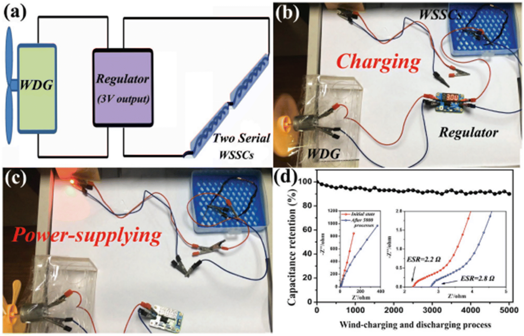 | ||
| Fig. 32 (a) Pictorial representation of the fabrication of wind-charging system, (b) real-time picture of charging process in WSSCs by the harvesting of wind energy, (c) digital photograph of lighting a red lamp with WSSCs after completely charging, and (d) retention of capacitance after wind-charging and discharging procedures. Inset representing the Nyquist plot of the device before and after 5000 cycles. Reproduced with permission from ref. 73 Copyright (2017), WILEY-VCH Verlag GmbH & Co. KGaA, Weinheim. | ||
The preparation of a 3D nanoarchitecture on flexible current collector is a suitable method for the fabrication of portable and wearable power sources. Li et al.74 developed a flexible and efficient electrode with an electrospun CF substrate possessing hierarchical porous V2O5 nanosheets via the solvothermal method. The formation of a 3D network was clear in the FESEM image, as shown in Fig. 33a. The cross-sectional view of the prepared electrospun CF indicates that the substrate possessed a thickness of about 87 μm, as shown in the inset in Fig. 33a. An average diameter of around 270 nm was obtained for the electrospun nanofiber and it possessed a smooth surface (Fig. 33b). A uniform 1D hierarchical architecture could be observed from the FESEM micrograph, as shown in the inset of Fig. 33c. According to the enlarged view of this SEM image (Fig. 33c), it was found that the 1D architecture was composed of ultrathin sheet-like subunits, which exhibited uniform growth over the surface of the electrospun CF.
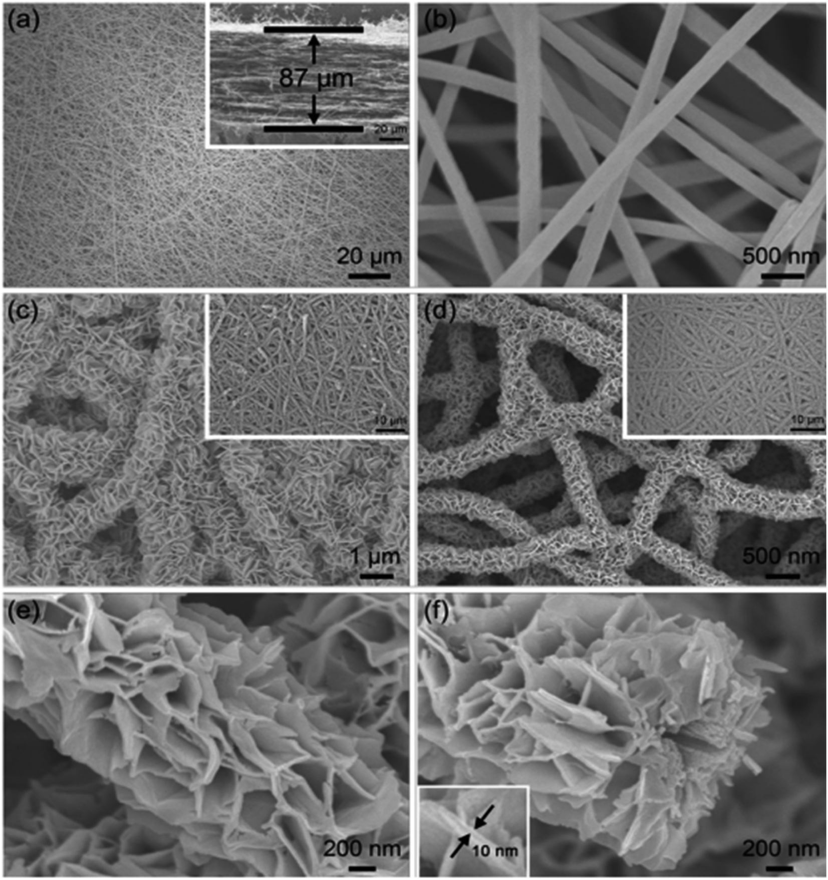 | ||
| Fig. 33 FESEM images of (a and b) electrospun CF substrate at different magnifications (inset image (a) cross-sectional view of ECF), (c) V–O precursor nanosheet array with inset showing its large aerial view and (d–f) crystalized V2O5 at various magnifications, inset of (d) showing the large aerial view and inset of (f) showing the nanosheet with magnified structure. Reproduced with permission from ref. 74 Copyright (2015), WILEY-VCH Verlag GmbH & Co. KGaA, Weinheim. | ||
In another study, after low-temperature annealing of a V–O precursor in air, it was fully converted to V2O5 crystalline nanosheets. Subsequently, CF was found to act as a robust support. The morphology of the as-prepared V2O5 architecture was still maintained after the annealing procedure as shown in Fig. 33d. The magnified images of the V2O5 architecture provided in Fig. 33e and f show perpendicularly cross-linked V2O5 with a porous structure, which exhibited a sheet-like morphology. It consists of an open space between individual nanosheets (evident from the inset image of Fig. 33f), which facilitates the easy penetration of the electrolyte-ions, and hence produced an efficient electrochemical performance as an electrode-active material in an SC. An asymmetric hybrid supercapacitor device was assembled using V2O5-electrospun CF as the anode and electrospun freestanding CF as the cathode. The assembled hybrid SC exhibited excellent cyclic stability for 10000 cycles with a decay of 10.7% capacitance after completing the cycling study. The SC possessed an excellent energy density of 22.3 W h kg−1 at the corresponding power density of 1500 W kg−1 and efficient mechanical flexibility. Furthermore, the flexibility of the SC was evaluated by bending it at different bending angles, exhibiting excellent mechanical stability during the testing. The electrochemical characteristics of this SC was maintained even after bending it for 200 times, which demonstrated prominent mechanical robustness for practical applications. This study presented an effective method for the fabrication of hybrid electrodes for flexible SCs.
Textile energy storage systems utilizing the features of wearable electronics are rapidly developing, but the fabrication of CF electrodes with better capacitances to generate higher energy densities and power densities is still a challenge. Qin et al.75 fabricated carbon cloth (CC) enriched with nitrogen/oxygen (N/O), which possessed a large surface area and accurate pore volume, via the electrochemical oxidation approach. The CC electrochemically treated for a duration of 3 min (3-CC), pristine CMF bundles and electrochemically-treated CF bundles (3-CMF) possessed good mechanical strength and flexibility during the deformation test. CC and 3-CC did not undergo breakage when wound on a glass rod with a diameter of ∼6 mm and unfolded afterwards. CC and 3-CC were found to maintain their original structure (Fig. 34a–c). The bare CF bundle and electrochemically-treated CF bundle could be folded into shaped logos (Fig. 34d and e) and weaved into a cloth with an area of ∼1–5 cm2 using cotton threads (Fig. 34f). The CMF bundle composed of a crossed warp and weft possessed a diameter of ≈400 μm, as can be observed in the SEM image (Fig. 34g). After completing the oxidation procedure, the grooves on the surface and embossments were found to be deeper and clear in comparison with the bare CMF (Fig. 34h and i).
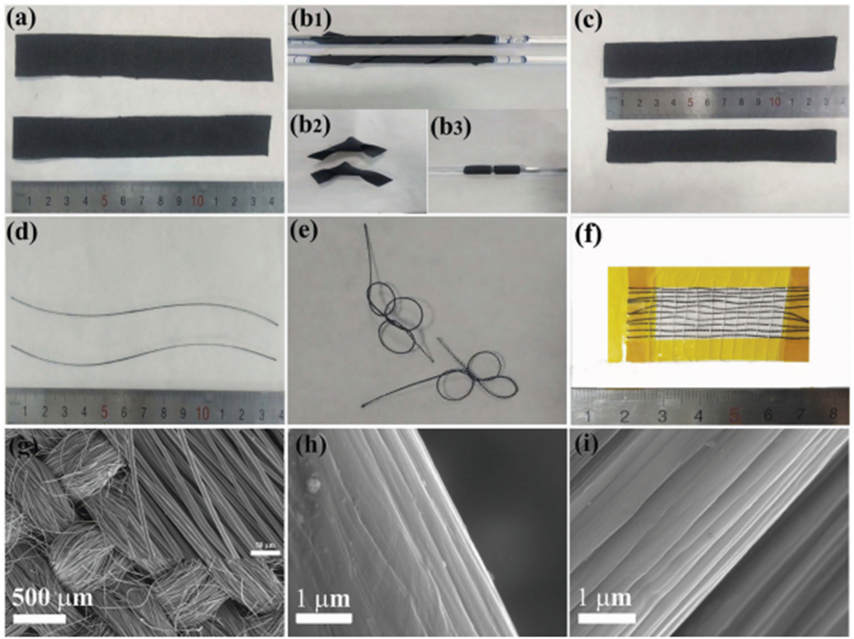 | ||
| Fig. 34 Morphological study of CF, CC and 3-CC. (a) Optical images of CC (top) and 3-CC (bottom) before shape changing, (b1 and b3) wound on a glass rod and (b2) kinked, (c) after shape changing; (d) bundles of pristine CF (top) and CF with electrochemical treatment (bottom), (e) kinked; (f) weaved with white cotton threads; SEM images of (g) CC (inset: its high magnification image) and (h) pristine CF fiber at high magnification and (i) with electrochemical treatment. Reproduced with permission from ref. 75 Copyright (2017), WILEY-VCH Verlag GmbH & Co. KGaA, Weinheim. | ||
CC and 3-CC electrode-based fiber-shaped and fabric-based SCs were fabricated, as shown in Fig. 35a. The fiber-shaped SC exhibited a higher capacitance of 32 mF cm−2 than that of the SC fabricated with CC (20 mF cm−1) (Fig. 35b). The cyclic stability analysis using GCD measurement is shown in Fig. 35c, where it can be seen that the SCs based on the CC and 3-CC electrodes exhibited a capacitance retention of 99% and 90%, respectively and the GCD curves are shown as inset images. These results show that the SCs exhibited excellent cycling stability. The volumetric energy density of the SC fabricated with the 3-CC electrode was about 6.8 mW h cm−3, which was found to be greater than the SC fabricated with the CC electrode (≈1.6 mW h cm−3), as shown in Fig. 35d. The SCs maintained their capacitance when bending to different bending angles, which indicates their good stability implementation in wearable textile devices. The fiber-shaped SCs fabricated with both 3-CC and CC electrodes retained their efficient electrochemical properties while bending for different cycle numbers, indicating their good flexibility. For example, about 94% and 85% capacitance was maintained during bending of the SC fabricated with the CC and 3-CC electrodes, respectively, as depicted in Fig. 35e and the CV curves obtained are given in the inset. In addition, the SC fabricated using the 3-CC electrode maintained a capacitance of ∼97% even after completing 900 cycles while bent at 720°, which was found to be higher than that of the SC fabricated with the CC electrode (about 79%), as shown in Fig. 35f and the CV curves obtained are given in the inset. These hierarchical nanostructured electrodes contained a large number of active-sites, which helped in enhancing the capacitance of the SCs.
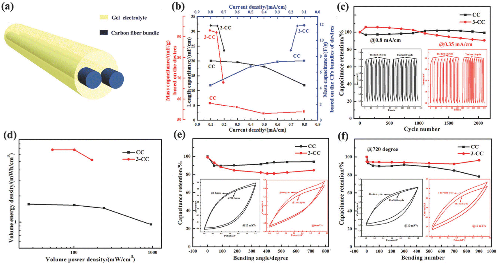 | ||
| Fig. 35 Electrochemical analysis of two-fiber shaped SC with CC and 3-CC bundles: (a) schematic of fiber-shaped SC; (b) rate calculation based on GCD at various current densities; (c) cyclic stability; and (d) Ragone plot. Retention of capacitance with (e) bending at 0° and 720° (inset corresponds to CV before and after bending), (f) stability in bending at 720° (inset representing the CV before and after bending). Reproduced with permission from ref. 75 Copyright (2017), WILEY-VCH Verlag GmbH & Co. KGaA, Weinheim. | ||
4.5 Carbon fiber-based hybrid electrodes
Using an in situ growth method, Yang et al.33 prepared (NixCo1−x)9Se8 solid solution series on CFC substrate. The (Ni0.1Co0.9)9Se8 nanodendrite arrays were found to exhibit dense growth on the CFC substrate. Before initiating the growth, the CFC substrate was pre-treated by soaking it in a nitric acid and sulfuric acid mixture to introduce a non-uniform surface, which was favourable for its growth. The SEM images in Fig. 36a and b show the surface morphology of the hierarchical 3D nano-dendrite arrays grown on the CFC substrate. The CV analysis of the SC electrode was performed in a three-electrode cell configuration at different scan rates of 5, 10, 15, 20, 25, and 30 mV s−1 and the resultant CV curves are depicted in Fig. 36c. The CV curve of the system was recorded in the potential window of 0.05–0.55 V an at the current density of 5 A g−1, which delivered a specific capacitance of about 591.1 F g−1. The as-fabricated SC electrode was tested in standard, folded, pulled, and twisted states and the CV curves obtained in each state at a constant scan rate of 50 mV s−1 are shown in Fig. 36d. The CV curves were found to be identical in each procedure, showing the excellent flexibility of the SC. In the case of the assembled device, the GCD measurements were repeated in these states (such as standard, folded, pulled, and twisted) and the resultant discharge curves are depicted in Fig. 36e, where it can be seen that the discharge curves exhibited a deviation in the various states (digital images at various states are given as inset). The asymmetric SC exhibited a capacitance retention of 88.8% after 3500 cycles (Fig. 36f). An asymmetric SC was fabricated with the structure of (Ni0.1Co0.9)9Se8@CFC//PVA/KOH//GO@CFC and two of these SCs were connected in series to light an LED, as shown in Fig. 36g. The asymmetric SC exhibited an energy density of 17 W h kg−1 at the corresponding power density of 3.1 kW kg−1 and 13.7 W h kg−1 at a corresponding power density of 10 kW kg−1 (Fig. 36h) and these performance metrics showed that this asymmetric SC can satisfy the growing demands in wearable electronics. Jost et al.76 developed a textile SC with knitted-CF and activated carbon ink. This textile SC exhibited a specific capacitance of 0.51 F cm−2 at a scan rate of 10 mV s−1. The electrochemical performance of this textile SC was comparable with the standard activated-CF electrode under similar conditions with good flexibility.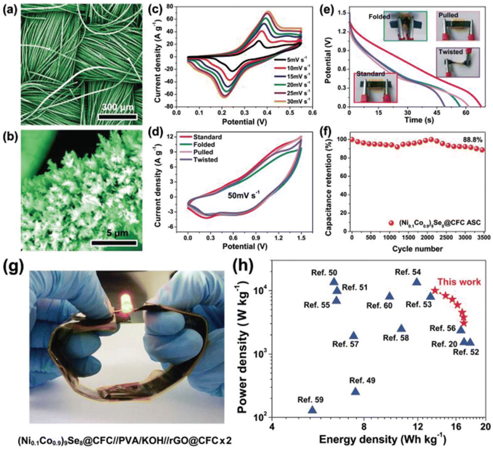 | ||
| Fig. 36 (a and b) SEM images of (Ni0.1Co0.9)9Se8 nanodendrite array grown on CFC; (c) CV curves at different scan rates; (d) CV curves at a scan rate of 5 mV s−1 and (e) GCD curves at 1 A g−1 for the asymmetric flexible SC in various bending conditions; (f) capacitance retention curve; (g) LED indicator lit by two (Ni0.1Co 0.9)9Se8@CFC//PVA/KOH//rGO@CFC asymmetric supercapacitors connected in series and (h) Ragone plot comparing other reports on nickel-cobalt sulfides and selenides. Reproduced with permission from ref. 33 Copyright (2018), WILEY-VCH Verlag GmbH & Co. KGaA, Weinheim. | ||
By employing ammonia activation and direct carbonization procedure, Zhan et al.77 synthesized blow-spun activated CF and further used it as an electrode-active material to fabricate a flexible asymmetric hybrid SC. The salient features of this electrode such as highly conducting network, doping with nitrogen, controlled pore structure and surface properties, helped in achieving a good electrochemical performance. The asymmetric SC exhibited a high energy of 98 W h kg−1 and 9 W h kg−1 at a corresponding power density of 400 W kg−1 and 34 kW kg−1, respectively. With the application of the dipping-drying method, Zhang et al.78 introduced CNT/MnO2 on an activated CF felt substrate. The fabricated flexible SC exhibited an area specific capacitance of 4148 mF cm−2 with an energy density of 141 μW h cm−2 at a corresponding power density of 4466 μW h cm−2. The flexibility of this SC was evaluated while bending it for 100 cycles, indicating its high flexibility. Zhou et al.79 proposed an effective strategy to develop molten-NaNH2 activated CF cloth for the fabrication of a flexible asymmetric SC. Here, commercially available CF cloth was oxidized with the aid of a wet-chemical approach and activated with molten-NaNH2. The as-prepared electrode-active material possessed many desirable features such as efficient wettability, large surface area, good conductivity and high mechanical strength. Consequently, the SC electrode delivered a high area specific capacitance of 744.5 mF cm−2 at a current density of 1 mA cm−2 with a capacitive retention of 96.94% in 6 M KOH after 10000 cycles. In another report, a flexible solid-state SC was fabricated using a free-standing and porous nanohybrid aerogel containing carbon nanosphere fiber (CNPF)/molybdenum disulfide (MoS2)/rGO as electrodes and H2SO4/PVA gel electrolyte.80 The CNPF/MoS2/rGO SC electrode exhibited a specific capacitance of 1144.3 F g−1 at a scan rate of 2 mV s−1. A capacitance retention of 98% was obtained even after completing 10000 cycles at the current density of 5 mA cm−2. The CNPF/MoS2/rGO SC electrode delivered an energy density of 57.5 μW h cm−2 at the corresponding power density of 28.8 W h kg−1 together with good bendability. Wei et al.81 fabricated a hybrid Zn-ion SC using a polypyrrole/p-phenylenediamine/CF electrode. The as-fabricated hybrid SC delivered a large specific capacity of about 47.6 mA h g−1 at a current density of 0.2 A g−1 and found to maintain a capacitance of 85.4% immediately after 1000 cycles and 78.5% after completing 5000 cycles. A coaxial fiber-type electrode was fabricated by Xu et al.82 by wrapping carbon paper over MnO2-modified nanoporous gold wire. The fabricated SC exhibited an area specific capacitance of 12 mF cm−2 and energy density of 5.4 μW h cm−2 with long cyclic stability. With the aid of an in situ growth conductive wrapping approach, Tao et al.83 fabricated a polypyrrole/MnO2/CF-based hybrid electrode. The SC fabricated with this hybrid electrode structure exhibited a volume specific capacitance of 69.3 F cm−3 at a current density of 0.1 A cm−3. Also, this SC delivered an energy density of 6.16 × 10³ W h cm−3 at the corresponding power density of 0.04 W cm−3. To introduce efficient durability and longer cycle life, Shin et al.84 fabricated a veil-based flexible SC electrode using activated-CF (ACF). An optical image of the ACF veil is presented in Fig. 37a, which was comprised of a porous network structure of non-uniformly distributed ACF possessing a thickness in the range of 100 μm (Fig. 37b and c). The permeability of this electrode was examined, and it was found that its permeability is almost the same as that of linen, cotton and nylon (Fig. 37d), representing its potential in wearable textile application. The procedure for the synthesis of the ACF veil SC electrode involves various steps including activation of carbon, dispersion, filtration and extraction, as shown in Fig. 37e.
 | ||
| Fig. 37 (a) Optical image of ACF veil. SEM images: (b) top view and (c) side view, (d) permeability of air in the network; and (e) process for the synthesis of ACF veil. Reproduced with permission from ref. 84 Copyright (2018), WILEY-VCH Verlag GmbH & Co. KGaA, Weinheim. | ||
The electrochemical performance evaluation of the ACF veil SC electrode was conducted in a two-electrode cell configuration using PVA/H3PO4 gel electrolyte, as shown in Fig. 38a. The CV (Fig. 38b) and GCD (Fig. 38c) measurements were also performed at different scan rates of 1, 3, 5, and 10 mV s−1 and different current densities ranging from 77.7 to 466.4 mA g−1, respectively, at the potential of 1 V. The rectangular CV curves and triangular GCD curves proved that the charge storage occurs via EDL formation. The Nyquist plot obtained for the SC is depicted in Fig. 38d, where it can be seen that in the high frequency region, diffuse resistance is generated due to slower ion diffusion. A rapid reduction in open circuit voltage was also observed in the prepared SC, where 50% of energy was conserved after charging for 5.5 h (Fig. 38e). The observed potential drop was proportional to the square root of time (Fig. 38f), which indicates that the diffusion-controlled ion concentration variation is the dominant mechanism of self-discharge. In another study, Pan et al.85 reported the preparation of a flexible textile SC electrode based on a CNT/PANI fiber composite, which delivered a specific capacitance of 272.7 F g−1. This composite electrode was further integrated to generate an energy textile, enabling the conversion of solar energy toward electrical energy besides storing and producing a photoelectric conversion and storage efficiency of 2.1%.
 | ||
| Fig. 38 (a) Schematic representation of veil-based SC; (b) CV curves; (c) GCD curves; and (d) Nyquist plot. Inset represents the high frequency region. (e) Reduction in OCV with time and (f) OCV with square root of time. Reproduced with permission from ref. 84 Copyright (2018), WILEY-VCH Verlag GmbH & Co. KGaA, Weinheim. | ||
According to the above discussion, it can be seen that CFs can be used both as a substrate for SC electrodes and electrode-active materials to fabricate SCs. Due to the prominent features of CFs such as flexibility and electrochemical stability, they can be considered suitable materials for the fabrication of flexible and wearable SCs together with other electrode-active materials. Table 1 provides the outstanding features of the CF-based SCs reported in the literature.
| Sl no. | Electrode material | Synthesis method | Major observations | Ref. |
|---|---|---|---|---|
| 1 | Coaxial MnO2–CNF cable mat | Electrodeposition | Coin cell symmetric SC gives a specific capacitance of 47 F g−1 at current density of 0.5 A g−1 within a potential window of 0 to 1.6 V | 86 |
| 2 | MnO2/CF hybrid fiber | Electrochemical deposition | Solid state device shows a volumetric energy density 3.8 mW h cm−3 at a power density 89 mW cm−3 | 87 |
| It possesses an efficient flexibility 85.8% capacitance retention after 10000 cycles |
||||
| 3 | Meso-macroporous nano-CF | Electrospun method | Symmetric device with NCF having 138 F g−1 at a scan rate of 5 mV s−1 and 98 F g−1 at a scan rate of 100 mV s−1 | 88 |
| 4 | Free-standing porous coaxial carbon nanofiber | Coaxial electrospinning and template method | Energy density of 48.6 ± 3 W h kg−1 and power density 67.5 ± 1 W h kg−1 in a two-electrode system | 89 |
| 5 | Polypyrrole-doped with dodecyl benzene sulfonate | Electrochemical deposition | Energy density and power density of 1.20 mW h cm−3 and 0.59 W cm−3 at a discharge current density of 1.50 A cm−3 using LiCl/PVA electrolyte | 90 |
| 6 | Ni–Co selenide on CF paper | Selenization approach | Symmetric SC device possesses volumetric capacitance of 14.55 F cm−3 at a current density of 1 mA cm−2 and a volumetric energy density of 0.47 mW h cm−3 at a current density of 10 mA cm−2 | 91 |
| 7 | CNT fiber/3D porous CNTs/PANI | Electrophoretic deposition and electrochemical polymerization | Specific capacitance of 67.31 mF cm−2 at a current density of 0.5 mA cm−2 and it maintains a capacitance of 99.8% even bending it to 180° for 500 cycles | 92 |
| 8 | MnO2 with cotton derived carbon cloth | Pyrolysis treatment | Area specific capacitance of 202 mF cm−2 with area specific energy density 30.1 μW h cm−2 at a power density of 0.15 mW cm−2. It shows a capacitance retention of 87.7% after 5000 cycles | 93 |
| 9 | NiCo2O4@MnO2 core shell | Hydrothermal deposition method | Area specific capacitance of 1.55 F cm−2 at 2 mA cm−2 with higher energy density of 1.983 mW h cm−2 at a power density of 1.72 mW cm−2 with a stability over 8000 cycles at a current density of 50 mA cm−2 | 94 |
| 10 | NiCo layered double hydroxide | In situ growth with substitution | Flexible device holds a specific capacity of 1377 mC cm−2 at a current density of 1 mA cm−2 with 70% capacitance retention and 99% coulombic efficiency over 10000 cycles |
95 |
| 11 | Hollow N-doped CF embedded with graphene nanosheet | Coaxial electrospinning and thermal treatment | In a three-electrode system it delivers a specific capacitance of 249 F g−1 at a current density of 1 A g−1 with capacitance retention of 99% over 5000 cycles in a two-electrode arrangement | 96 |
| 12 | BN co-doped CNTs grown over the surface of CF around carbon cloth | Single-step pyrolysis-based thermal chemical vapour deposition | It delivers a volumetric capacitance of 21.4 F cm−3 with 741.8 mW h cm−3 energy density at a power density of 1 kW cm−3 | 97 |
| 13 | 3D nanocomposite of CNTs-carbonized cotton fiber-PANI | Single-step chemical vapour deposition | Area specific capacitance of 3.1 F cm−2 at a current density of 2 mA cm−2 with a cyclic stability of 91% after 2000 cycles | 98 |
| 14 | CuCo2O4@Ni(OH)2/CFC | Simple step procedure | Asymmetric SC device gives a higher energy density 58.9 W h kg−1 at a power density of 400 W kg−1 | 99 |
| 15 | Ni3S2/polyaniline on CF | Electrodeposition and in situ polymerization | Flexible asymmetric SC gives an energy density of 35.7 W h kg−1 at a power density of 850 W kg−1 | 100 |
| 16 | NiCo2S4 nanotube grown over CF | Hydrothermal method | Asymmetric device gives energy density of 24.78 W h kg−1 at a power density of 1770.13 W kg−1 | 101 |
| 17 | NiCo2O4 decorated PAN/lignin-based CF | Electrospinning, stabilization, carbonization followed by hydrothermal method | Asymmetric SC device gives a specific capacitance of 134.3 F g−1 at a current density of 1 A g−1 with an energy density of 47.75 W h kg−1 at a power density of 799.53 W kg−1 | 102 |
| 18 | Ni0.4Co0.6(OH)2 grown over CF | Hydrothermal method | Symmetric solid-state SC delivers a specific capacitance of 1816 F g−1 at a current density of 1 A g−1 with a capacitance retention of 98.3% after 5000 cycles | 103 |
| 19 | Ti3C2Tx MXene/CF | Electrospinning of PAN | Gravimetric capacitance of 120 F g−1 at 2 mV s−1 with 98% capacitance retention after 10000 cycles |
104 |
| 20 | Crystalline tetraaniline nanofiber deposited on oxidized CFC | Solution-based self-assembly approach | Capacitance retention of 99.97% after 10000 cycles in H2SO4/Na2SO4/PVA electrolyte |
105 |
| 21 | V2O5 nanosheet assembled over 3D CF | Hydrothermal method | Free-standing asymmetric SC gives energy density of 0.928 mW h cm−3 at a power density of 17.5 mW cm−3 with a capacitance retention of 89.7% after 2000 cycles | 106 |
| 22 | FeNiP@CoNi-LDH grown on carbon cloth | Hydrothermal and phosphorization treatment | Aqueous symmetric SC gives an energy density of 87.3 W h kg−1 at a power density of 408.8 W kg−1 with capacitance retention of 73.9% after 20000 cycles |
107 |
| 23 | 2D 1T-MoS2/1D Cu(OH)2 over CF paper | In situ growth | It exhibits an energy density of 0.13 mW h cm−2 at a power density of 0.375 mW cm−2. The device exhibited 90.8% capacitance retention after 20000 cycles |
108 |
| 24 | Polypyrrole@CF yarn electrode | Electrosynthesis | It delivers a specific capacitance of 50.08 F cm−3 with an energy density of 4.45 mW h cm−3 and it maintains a capacitance retention of 89% after 5000 bending cycles | 109 |
| 25 | Polyaniline/manganese hexacyanoferrate | Electrochemical co-polymerization method | Specific capacitance of 730 F g−1 at a current density of 1 A g−1 with a capacitance retention of 85% after 1000 cycles | 110 |
| 26 | Carbon nanofibers@polypyrrole@graphene film | Electrochemical deposition | Specific capacitance of 336.2 F g−1 at 2 mV s−1 with a capacitance retention of 98% after 2500 cycles | 111 |
| 27 | Ultrathick CNT fiber | Sonochemical process | Volumetric capacitance of 523.3 F cm−3 with a flexibility of 98.4% at a bending angle 90° | 112 |
| 28 | CF surface-grown over helical CNTs and polyaniline | Catalytic CVD and in situ polymerization | Specific capacitance of 439 F g−1 at a current density of 0.05 A g−1 and a capacitance retention of 95.4% over 500 cycles | 113 |
| 29 | Micro-nano integrated core sheath CF electrode | Space confined hydrothermal method | Volumetric capacitance of 27 F cm−3 with energy density of 3.75 mW h cm−3 at a power density of 612 mW cm−3 | 114 |
| 30 | MnO2 nanograss on porous CFC | Simple wet-chemical method | Energy density of 841 μW h cm−2 with a capacitance retention of 96% after 20000 cycles |
115 |
5. Future perspectives
CF-based flexible SCs are futuristic devices for widespread wearable electronic applications. The utilization of CFs as flexible substrates for wearable SCs is a facile method to realize on-body applications. However, one of the major disadvantages associated with the use of CFs in the fabrication of SCs is that it depends on the purity of their precursor. Although CFs are highly flexible in their virgin state, during various treatment processes, there is a high chance that their flexibility, structural pattern, etc. will be reduced, and thus it is compulsory to optimize the experimental parameters before their use. Another parameter affecting the performance of CFs is the synthesis method adopted. An optimized concentration of precursor materials is necessary for the introduction of CFs with a porous morphology to establish a high performance in SC fabrication. The synthesis of CFs via a low-cost approach is mandatory, such as synthesis from biomass-derived materials, where only a few reports based on the synthesis of CF from biomass materials are available in the literature. The derivation of CFs from biomass ingredients opens a facile pathway for their environment-friendly preparation. A widespread study on suitable biomaterials that are favourable for the synthesis of CFs may present a facile and cost-effective approach for their large-scale synthesis. The long-term stability of CF-based electrodes is a major criterion, which depicts their durability in application. However, a reduction in the stability of CNFs due to restacking and other structural distortions is possible, which limits their performance in long-term functioning. Another disadvantage of CNFs is their less eco-friendly synthesis, and hence the synthesis of CNFs from less toxic materials will be appreciated in the future, such as their synthesis from biomass-based materials. By considering these features, CFs can be used as potential electrode candidates in futuristic wearable supercapacitors with high flexibility and long cyclic stability.6. Summary
CFs are considered promising sustainable materials for a variety of applications due to their high flexibility, easy synthesis, good mechanical strength, etc. In this review, we described the prominent features of CFs, making them suitable for the preparation of SC electrodes. The various methods for the synthesis of CFs were discussed by emphasizing the microstructure and surface morphology of the produced CFs. The various precursors used for the synthesis of CFs were explained based on their uniqueness to obtain a particular morphology. Further, the application of CFs in flexible SCs was explained in detail with the help of literature data. Various synthetic methods such as drop-casting or spin-coating approaches were employed for the synthesis of flexible electrodes. The easy integration of CF-based SCs with flexible and wearable electronic devices was examined with the help of various electrochemical analysis tools such as CV and GCD measurements performed at various bending angles and in different states such as folded, pulled, twisted, standard. Furthermore, we discussed the recent developments in CF-based electrode-active materials for wearable SCs. CF-based electrode materials endow excellent flexibility and electrochemical performance to the fabricated flexible SCs including symmetric and asymmetric SCs. The various synthetic approaches to prepare flexible electrodes using polymer-based solid-state gel electrolytes were discussed in detail. CF-based electrode-active materials should be synthesized in a cost-effective, facile and eco-friendly manner to make them sustainable materials for the future. The preparation of CF-based hybrids or nanocomposites for SC electrode application, which helped in achieving a high specific capacitance, was included. The demonstration of CF-based SC electrodes to meet the requirements of flexible electronic devices such as in the field of telecommunication and health-monitoring systems was also provided. CF-based flexible SCs are highly recommended for application in flexible and miniaturized-devices to improve daily life. Thus, the further development and utilization of CF-based wearable SCs will enable the fabrication of sustainable on-body wearable devices in the future.Data availability
Data sharing not applicable – no new data generated. Data availability is not applicable to this article as no new data were created or analysed in this study.Conflicts of interest
The authors declare no conflict of interest.References
- Z. Guo, et al., Flexible self-standing carbon fabric electrode prepared by using simple route for wearable applications, J. Mater. Sci.: Mater. Electron., 2020, 31(2), 1554–1565 CrossRef CAS.
- S. A. Thomas and J. Cherusseri, Boron Carbon Nitride (BCN): Emerging Two-Dimensional Nanomaterial for Supercapacitors, J. Mater. Chem. A, 2023, 11, 23148–23187 RSC.
- C. Wu, et al., Free-standing graphene-based porous carbon films with three-dimensional hierarchical architecture for advanced flexible li–sulfur batteries, J. Mater. Chem. A, 2015, 3(18), 9438–9445 RSC.
- Y. Han, et al., Review of flexible supercapacitors using carbon nanotube-based electrodes, Appl. Sci., 2023, 13(5), 3290 CrossRef CAS.
- S. A. Thomas and J. Cherusseri, A Review of Nb2CT x MXene as an Emerging 2D Material: Synthesis, Applications in Rechargeable Batteries and Supercapacitors, Progress, and Outlook, Energy Fuels, 2023, 37(11), 7555–7576 CrossRef CAS.
- H. J. Sim, et al., Biomolecule based fiber supercapacitor for implantable device, Nano Energy, 2018, 47, 385–392 CrossRef CAS.
- Y. Zhang, et al., Flexible and stretchable lithium-ion batteries and supercapacitors based on electrically conducting carbon nanotube fiber springs, Angew. Chem., Int. Ed., 2014, 53(52), 14564–14568 CrossRef CAS PubMed.
- S. A. Thomas and J. Cherusseri, Strategically designing layered two-dimensional SnS2-based hybrid electrodes: A futuristic option for low-cost supercapacitors, J. Energy Chem., 2023, 85, 394–417 CrossRef.
- S. Banerjee, et al., Capacitor to supercapacitor, in Handbook of Nanocomposite Supercapacitor Materials I, Springer, 2020, pp. 53–89 Search PubMed.
- S. A. Thomas, et al., MXene based hybrid materials for supercapacitors: Recent developments and future perspectives, J. Energy Storage, 2022, 55, 105765 CrossRef.
- S. G. Krishnan, et al., Energy storage in metal cobaltite electrodes: Opportunities & challenges in magnesium cobalt oxide, Renewable Sustainable Energy Rev., 2021, 141, 110798 CrossRef CAS.
- K. Krishnamoorthy, et al., Supercapacitive properties of hydrothermally synthesized sphere like MoS2 nanostructures, Mater. Res. Bull., 2014, 50, 499–502 CrossRef CAS.
- J. Cherusseri, et al., Flexible supercapacitor electrodes using metal–organic frameworks, Nanoscale, 2020, 12(34), 17649–17662 RSC.
- L. Li, et al., Advances and challenges for flexible energy storage and conversion devices and systems, Energy Environ. Sci., 2014, 7(7), 2101–2122 RSC.
- S. A. Thomas, et al., Translation of supercapacitor technology from laboratory scale to commercialization, in Supercapacitors, Elsevier, 2024, pp. 371–395 Search PubMed.
- P. G. Bruce, B. Scrosati and J. M. Tarascon, Nanomaterials for rechargeable lithium batteries, Angew. Chem., Int. Ed., 2008, 47(16), 2930–2946 CrossRef CAS PubMed.
- S. A. Thomas, J. Cherusseri and D. N. Rajendran, 2D Nickel Sulfide Electrodes with Superior Electrochemical Thermal Stability along with Long Cyclic Stability for Supercapatteries, Energy Technol., 2024, 2301641 CrossRef.
- S. A. Thomas, J. Cherusseri and D. N. Rajendran, Rapid Synthesis of Hierarchical Tin Disulfide (SnS2) Nanostructures by a Microwave-Assisted Hydrothermal Method for High-Performance Supercapatteries, ACS Appl. Electron. Mater., 2024, 6(5), 3346–3361 CrossRef CAS.
- S. G. Krishnan, et al., 2D Materials for supercapacitor and supercapattery applications, in Adapting 2D Nanomaterials for Advanced Applications, ACS Publications, 2020, pp. 33–47 Search PubMed.
- G. Jeong, et al., Prospective materials and applications for Li secondary batteries, Energy Environ. Sci., 2011, 4(6), 1986–2002 RSC.
- J. W. Fergus, Recent developments in cathode materials for lithium ion batteries, J. Power Sources, 2010, 195(4), 939–954 CrossRef CAS.
- S. A. Thomas, et al., “Water-in-salt” electrolyte—toward high-voltage aqueous supercapacitors, in Supercapacitors, Elsevier, 2024, pp. 289–315 Search PubMed.
- Z. Yan, et al., Recent advances in flexible wearable supercapacitors: properties, fabrication, and applications, Advanced Science, 2024, 11(8), 2302172 CrossRef CAS PubMed.
- N. M. Badawi, et al., A review of wearable supercapacitors fabricated from highly flexible conductive fiber materials, New Carbon Mater., 2023, 38(2), 211–225 CrossRef CAS.
- J. Cherusseri, et al., Recent trends in transition metal dichalcogenide based supercapacitor electrodes, Nanoscale Horiz., 2019, 4(4), 840–858 RSC.
- A. Mishra, et al., Carbon cloth-based hybrid materials as flexible electrochemical supercapacitors, ChemElectroChem, 2019, 6(23), 5771–5786 CrossRef CAS.
- M. R. Pallavolu, et al., Scalable synthesis of binder-free hierarchical MnCo2O4 nanospikes/Ni (OH) 2 nanosheets composite electrodes for high-capacity supercapatteries, J. Energy Storage, 2023, 73, 108999 CrossRef.
- A. H. Khadem, Recent Advances in Functional Fabric-Based Wearable Supercapacitors, Adv. Mater. Interfaces, 2024, 11(7), 2300724 CrossRef.
- S. Lee and G.-H. An, Interface engineering of carbon fiber-based electrode for wearable energy storage devices, Adv. Fiber Mater., 2023, 5(5), 1749–1758 CrossRef CAS.
- Y. Liang, D. Wu and R. Fu, Carbon microfibers with hierarchical porous structure from electrospun fiber-like natural biopolymer, Sci. Rep., 2013, 3(1), 1119 CrossRef PubMed.
- J. Ren, et al., One-pot synthesis of carbon nanofibers from CO2, Nano Lett., 2015, 15(9), 6142–6148 CrossRef CAS PubMed.
- J. Cherusseri, et al., Vertically aligned graphene–carbon fiber hybrid electrodes with superlong cycling stability for flexible supercapacitors, Small, 2019, 15(44), 1902606 CrossRef CAS PubMed.
- P. Yang, et al., Fractal (NixCo1−x) 9Se8 Nanodendrite Arrays with Highly Exposed () Surface for Wearable, All-Solid-State Supercapacitor, Adv. Energy Mater., 2018, 8(26), 1801392 CrossRef.
- R. Ojeda-López, et al., Tailoring synthesis conditions of carbon microfibers to enhance the microporosity, CO2 and CH4 adsorption by using the response surface methodology, Microporous Mesoporous Mater., 2020, 305, 110333 CrossRef.
- L. Wang, et al., Mesoporous carbon microfibers for electroactive materials derived from lignocellulose nanofibrils, ACS Sustainable Chem. Eng., 2020, 8(23), 8549–8561 CrossRef CAS PubMed.
- K. Saxena, P. Kumar and V. Jain, Synthesis of carbon microfibers by chemical vapor deposition during the catalytic decomposition of turpentine oil, New Carbon Mater., 2011, 26(5), 356–360 CrossRef CAS.
- E. Taer, W. Mustika, and R. Taslim, Synthesis of a carbon-activated microfiber from spider webs silk, in IOP Conference Series: Earth and Environmental Science, IOP Publishing, 2017 Search PubMed.
- Z. Yang, et al., Molten salt guided synthesis of carbon Microfiber/FeS dielectric/magnetic composite for microwave absorption application, Carbon, 2023, 202, 225–234 CrossRef CAS.
- L. Zhihua, et al., Hypha-templated synthesis of carbon/ZnO microfiber for dopamine sensing in pork, Food Chem., 2021, 335, 127646 CrossRef PubMed.
- F. Su, et al., Template synthesis of mesoporous carbon microfibers as a catalyst support for methanol electrooxidation, Ind. Eng. Chem. Res., 2007, 46(26), 9097–9102 CrossRef CAS.
- X. Jiang, CVD growth of carbon nanofibers, Phys. Status Solidi A, 2014, 211(12), 2679–2687 CrossRef CAS.
- G.-B. Zheng, et al., A model for the structure and growth of carbon nanofibers synthesized by the CVD method using nickel as a catalyst, Carbon, 2004, 42(3), 635–640 CrossRef CAS.
- G. Che, et al., Chemical vapor deposition based synthesis of carbon nanotubes and nanofibers using a template method, Chem. Mater., 1998, 10(1), 260–267 CrossRef CAS.
- C. Deeney, et al., Template-assisted synthesis of luminescent carbon nanofibers from beverage-related precursors by microwave heating, Molecules, 2019, 24(8), 1455 CrossRef CAS PubMed.
- C. Deeney, et al., Templated microwave synthesis of luminescent carbon nanofibers, RSC Adv., 2018, 8(23), 12907–12917 RSC.
- A. Gopalakrishnan, P. Sahatiya and S. Badhulika, Template-assisted electrospinning of bubbled carbon nanofibers as binder-free electrodes for high-performance supercapacitors, ChemElectroChem, 2018, 5(3), 531–539 CrossRef CAS.
- Y. Matsumoto, et al., Preparation of carbon nanofibers by hot filament-assisted sputtering, Mater. Sci. Eng., B, 2000, 74(1–3), 218–221 CrossRef.
- Y. Onuma, et al., Preparation of carbon nanofibers by hot-filament-assisted sputtering, Jpn. J. Appl. Phys., 2000, 39(7S), 4577 CrossRef CAS.
- Y. M. Ahmed, et al., Synthesis and characterization of carbon nanofibers grown on powdered activated carbon, J. Nanotechnol., 2016, 2016, 1–10 CrossRef.
- B. Gaud, et al., Synthesis of carbon nano fiber from organic waste and activation of its surface area, Int. J. Phys. Appl., 2019, 2766, 2748 Search PubMed.
- Ž. Kotanjac, et al., Synthesis of carbon nanofibers on large woven cloth, C, 2015, 1(1), 2–15 Search PubMed.
- X. Ling, et al., Core–shell structure γ-MnO2-PANI carbon fiber paper-based flexible electrode material for high-performance supercapacitors, J. Ind. Eng. Chem., 2021, 99, 317–325 CrossRef CAS.
- F. Niu, et al., Coral-like PEDOT nanotube arrays on carbon fibers as high-rate flexible supercapacitor electrodes, ACS Appl. Energy Mater., 2020, 3(8), 7794–7803 CrossRef CAS.
- J. Cherusseri and K. K. Kar, Ultra-flexible fibrous supercapacitors with carbon nanotube/polypyrrole brush-like electrodes, J. Mater. Chem. A, 2016, 4(25), 9910–9922 RSC.
- Y. Zhou, et al., Reclaimed carbon fiber-based 2.4 V aqueous symmetric supercapacitors, ACS Sustain. Chem. Eng., 2019, 7(5), 5095–5102 CrossRef CAS.
- M. Ramu, et al., A self-branched lamination of hierarchical patronite nanoarchitectures on carbon fiber cloth as novel electrode for ionic liquid electrolyte-based high energy density supercapacitors, Adv. Funct. Mater., 2020, 30(6), 1906586 CrossRef CAS.
- J. Li, et al., Flexible All-Solid-State Supercapacitor Fabricated with Nitrogen-Doped Carbon Nanofiber Electrode Material Derived from Polyacrylonitrile Copolymer, ACS Appl. Energy Mater., 2021, 4(6), 5830–5839 CrossRef CAS.
- J. Cherusseri and K. K. Kar, Hierarchically mesoporous carbon nanopetal based electrodes for flexible supercapacitors with super-long cyclic stability, J. Mater. Chem. A, 2015, 3(43), 21586–21598 RSC.
- W. Hu, et al., Electrochemical Performance of Coaxially Wet-Spun Hierarchically Porous Lignin-Based Carbon/Graphene Fiber Electrodes for Flexible Supercapacitors, ACS Appl. Energy Mater., 2021, 4(9), 9077–9089 CrossRef CAS.
- L. Gao, et al., Flexible fiber-shaped supercapacitor based on nickel–cobalt double hydroxide and pen ink electrodes on metallized carbon fiber, ACS Appl. Mater. Interfaces, 2017, 9(6), 5409–5418 CrossRef CAS PubMed.
- T. Wang, et al., 2-Methylimidazole-derived Ni–Co layered double hydroxide nanosheets as high rate capability and high energy density storage material in hybrid supercapacitors, ACS Appl. Mater. Interfaces, 2017, 9(18), 15510–15524 CrossRef CAS PubMed.
- A. D. Jagadale, et al., Binder-Free Electrodes of CoAl Layered Double Hydroxide on Carbon Fibers for All-Solid-State Flexible Yarn Supercapacitors, Energy Technol., 2016, 4(8), 997–1004 CrossRef CAS.
- J. Cherusseri, R. Sharma and K. K. Kar, Helically coiled carbon nanotube electrodes for flexible supercapacitors, Carbon, 2016, 105, 113–125 CrossRef CAS.
- C. Yang, et al., All-solid-state asymmetric supercapacitor based on reduced graphene oxide/carbon nanotube and carbon fiber paper/polypyrrole electrodes, J. Mater. Chem. A, 2014, 2(5), 1458–1464 RSC.
- Y. Liu, et al., Enhanced electrochemical performance of hybrid SnO2@MOx (M= Ni, Co, Mn) core–shell nanostructures grown on flexible carbon fibers as the supercapacitor electrode materials, J. Mater. Chem. A, 2015, 3(7), 3676–3682 RSC.
- X.-F. Lu, et al., High-performance supercapacitors based on MnO 2 tube-in-tube arrays, J. Mater. Chem. A, 2015, 3(32), 16560–16566 RSC.
- X. Lu, et al., A high-performance flexible and weavable asymmetric fiber-shaped solid-state supercapacitor enhanced by surface modifications of carbon fibers with carbon nanotubes, J. Mater. Chem. A, 2016, 4(46), 18164–18173 RSC.
- S. Liu, et al., Flexible polypyrrolone-based microporous carbon nanofibers for high-performance supercapacitors, RSC Adv., 2018, 8(45), 25568–25574 RSC.
- F. Tong, et al., NiS nanosheets with novel structure anchored on coal-based carbon fibers prepared by electrospinning for flexible supercapacitors, CrystEngComm, 2020, 22(9), 1625–1632 RSC.
- M. Ding, et al., Reduced graphene oxide/gC 3 N 4 modified carbon fibers for high performance fiber supercapacitors, New J. Chem., 2021, 45(2), 923–929 RSC.
- P. Yu, et al., Polyaniline nanowire arrays aligned on nitrogen-doped carbon fabric for high-performance flexible supercapacitors, Langmuir, 2013, 29(38), 12051–12058 CrossRef CAS PubMed.
- Y. Ai, et al., Meters-Long Flexible CoNiO2-Nanowires@ Carbon-Fibers Based Wire-Supercapacitors for Wearable Electronics, Adv. Mater. Technol., 2016, 1(8), 1600142 CrossRef.
- M. Shi, et al., Integrated Sustainable Wind Power Harvesting and Ultrahigh Energy Density Wire-Shaped Supercapacitors Based on Vertically Oriented Nanosheet-Array-Coated Carbon Fibers, Adv. Sustainable Syst., 2017, 1(5), 1700044 CrossRef.
- L. Li, et al., A flexible quasi-solid-state asymmetric electrochemical capacitor based on hierarchical porous V2O5 nanosheets on carbon nanofibers, Adv. Energy Mater., 2015, 5(17), 1500753 CrossRef.
- T. Qin, et al., Flexible and wearable all-solid-state supercapacitors with ultrahigh energy density based on a carbon fiber fabric electrode, Adv. Energy Mater., 2017, 7(20), 1700409 CrossRef.
- K. Jost, et al., Knitted and screen printed carbon-fiber supercapacitors for applications in wearable electronics, Energy Environ. Sci., 2013, 6(9), 2698–2705 RSC.
- C. Zhan, et al., Blow-spun N-doped carbon fiber based high performance flexible lithium ion capacitors, RSC Adv., 2020, 10(17), 9833–9839 RSC.
- J. Zhang, et al., Comprehensive approaches to three-dimensional flexible supercapacitor electrodes based on MnO2/carbon nanotube/activated carbon fiber felt, J. Mater. Sci., 2017, 52(10), 5788–5798 CrossRef CAS.
- S. Zhou, et al., Molten-NaNH2 activated carbon cloth with high areal capacitance and exceptional rate stability for flexible asymmetric supercapacitors, J. Mater. Sci., 2019, 54(12), 9111–9123 CrossRef CAS.
- Y. Lv, et al., Nanocellulose-derived carbon nanosphere fibers-based nanohybrid aerogel for high-performance all-solid-state flexible supercapacitors, J. Mater. Sci.: Mater. Electron., 2019, 30(9), 8585–8594 CrossRef CAS.
- B. Wei, et al., Highly flexible Zn-ion hybrid supercapacitors based on carbon fibers covalently combined with polypyrrole, Ionics, 2022, 29, 1–10 Search PubMed.
- H. Xu, et al., Flexible fiber-shaped supercapacitors based on hierarchically nanostructured composite electrodes, Nano Res., 2015, 8(4), 1148–1158 CrossRef CAS.
- J. Tao, et al., Solid-state high performance flexible supercapacitors based on polypyrrole-MnO2-carbon fiber hybrid structure, Sci. Rep., 2013, 3(1), 1–7 Search PubMed.
- D. Shin, et al., Breathable 3D supercapacitors based on activated carbon fiber veil, Adv. Mater. Technol., 2018, 3(11), 1800209 CrossRef.
- S. Pan, et al., Novel wearable energy devices based on aligned carbon nanotube fiber textiles, Adv. Energy Mater., 2015, 5(4), 1401438 CrossRef.
- C.-S. Liu, et al., MnO2-based carbon nanofiber cable for supercapacitor applications, J. Energy Storage, 2021, 33, 102130 CrossRef.
- J. Zhang, et al., High-performance all-solid-state flexible supercapacitors based on manganese dioxide/carbon fibers, Carbon, 2016, 107, 844–851 CrossRef CAS.
- L. Fan, et al., Nitrogen-enriched meso-macroporous carbon fiber network as a binder-free flexible electrode for supercapacitors, Carbon, 2016, 107, 629–637 CrossRef CAS.
- Y. Xiao, et al., Coaxial electrospun free-standing and mechanically stable hierarchical porous carbon nanofiber membranes for flexible supercapacitors, Carbon, 2020, 160, 80–87 CrossRef CAS.
- W. Zhou, et al., Polypyrrole doped with dodecyl benzene sulfonate electrodeposited on carbon fibers for flexible capacitors with high-performance, Electrochim. Acta, 2015, 176, 594–603 CrossRef CAS.
- P. Xu, et al., 3D Ni-Co selenide nanorod array grown on carbon fiber paper: towards high-performance flexible supercapacitor electrode with new energy storage mechanism, Electrochim. Acta, 2017, 241, 41–49 CrossRef CAS.
- J.-h. Liu, et al., A high performance all-solid-state flexible supercapacitor based on carbon nanotube fiber/carbon nanotubes/polyaniline with a double core-sheathed structure, Electrochim. Acta, 2018, 283, 366–373 CrossRef CAS.
- C. Wan, et al., A high-performance, all-textile and spirally wound asymmetric supercapacitors based on core–sheath structured MnO2 nanoribbons and cotton-derived carbon cloth, Electrochim. Acta, 2018, 285, 262–271 CrossRef CAS.
- X. Wu, et al., High flexibility and large energy density asymmetric fibered-supercapacitor based on unique NiCo2O4@ MnO2 core-shell nanobrush arrays electrode, Electrochim. Acta, 2019, 295, 532–539 CrossRef CAS.
- X. Xuan, et al., In situ growth of hollow NiCo layered double hydroxide on carbon substrate for flexible supercapacitor, Electrochim. Acta, 2019, 321, 134710 CrossRef CAS.
- X. Li, et al., Flexible all-solid-state supercapacitors based on an integrated electrode of hollow N-doped carbon nanofibers embedded with graphene nanosheets, Electrochim. Acta, 2020, 332, 135398 CrossRef CAS.
- R. Paul and A. K. Roy, BN-codoped CNT based nanoporous brushes for all-solid-state flexible supercapacitors at elevated temperatures, Electrochim. Acta, 2021, 365, 137345 CrossRef CAS.
- D. Xing, et al., Development of CNTs-carbonized cotton fiber/PANI 3D-nanocomposites for flexible energy storage and electromagnetic shielding applications, Electrochim. Acta, 2022, 427, 140847 CrossRef CAS.
- D. Zhu, et al., Rationally designed CuCo2O4@ Ni (OH) 2 with 3D hierarchical core-shell structure for flexible energy storage, J. Colloid Interface Sci., 2019, 557, 76–83 CrossRef CAS PubMed.
- L. Wang, et al., Construction of ultra-stable trinickel disulphide (Ni3S2)/polyaniline (PANI) electrodes based on carbon fibers for high performance flexible asymmetric supercapacitors, J. Colloid Interface Sci., 2020, 577, 29–37 CrossRef CAS PubMed.
- C. Liu and X. Wu, NiCo2S4 nanotube arrays grown on flexible carbon fibers as battery-type electrodes for asymmetric supercapacitors, Mater. Res. Bull., 2018, 103, 55–62 CrossRef CAS.
- D. Lei, et al., NiCo2O4 nanostructure-decorated PAN/lignin based carbon nanofiber electrodes with excellent cyclability for flexible hybrid supercapacitors, Polymer, 2017, 132, 31–40 CrossRef CAS.
- X. Wu, et al., A novel and facile step-by-step hydrothermal fabrication of peony-like Ni0. 4Co0. 6 (OH) 2 supported on carbon fiber cloth as flexible electrodes for advanced electrochemical energy storage, Sol. Energy Mater. Sol. Cells, 2018, 174, 325–332 CrossRef CAS.
- H. Hwang, et al., High-rate electrospun Ti3C2Tx MXene/carbon nanofiber electrodes for flexible supercapacitors, Appl. Surf. Sci., 2021, 556, 149710 CrossRef CAS.
- D. Wang, et al., High-crystalline tetraaniline nanofibers deposited carbon cloth as flexible electrode for high-performance solid-state supercapacitors, Surf. Coat. Technol., 2021, 424, 127626 CrossRef CAS.
- M. You, et al., V2O5 nanosheets assembled on 3D carbon fiber felt as a free-standing electrode for flexible asymmetric supercapacitor with remarkable energy density, Ceram. Int., 2021, 47(3), 3337–3345 CrossRef CAS.
- L. Wan, et al., Construction of FeNiP@ CoNi-layered double hydroxide hybrid nanosheets on carbon cloth for high energy asymmetric supercapacitors, J. Power Sources, 2020, 465, 228293 CrossRef CAS.
- G. Zhang, et al., 3D hetero-nanostructured electrode constructed on carbon fiber paper with 2D 1T-MoS2/1D Cu (OH)2 for flexible asymmetric solid-state supercapacitors, J. Power Sources, 2022, 523, 231031 CrossRef CAS.
- X. Liu, et al., Design and fabrication of high performance flexible supercapacitor with polypyrrole@ carbon fiber yarn electrode and redox active dopants, Synth. Met., 2021, 271, 116654 CrossRef CAS.
- R. S. Babu, et al., Novel polyaniline/manganese hexacyanoferrate nanoparticles on carbon fiber as binder-free electrode for flexible supercapacitors, Composites, Part B, 2018, 143, 141–147 CrossRef CAS.
- L. Chen, et al., Flexible all-solid-state supercapacitors based on freestanding, binder-free carbon nanofibers@ polypyrrole@ graphene film, Chem. Eng. J., 2018, 334, 184–190 CrossRef CAS.
- S. Lee, et al., Flexible supercapacitor with superior length and volumetric capacitance enabled by a single strand of ultra-thick carbon nanotube fiber, Chem. Eng. J., 2023, 453, 139974 CrossRef CAS.
- H. Luo, H. Lu and J. Qiu, Carbon fibers surface-grown with helical carbon nanotubes and polyaniline for high-performance electrode materials and flexible supercapacitors, J. Electroanal. Chem., 2018, 828, 24–32 CrossRef CAS.
- S. Zhai, et al., Hydrothermal assembly of micro-nano-integrated core-sheath carbon fibers for high-performance all-carbon micro-supercapacitors, Energy Storage Mater., 2017, 9, 221–228 CrossRef.
- H. Wang, et al., MnO2 nanograsses on porous carbon cloth for flexible solid-state asymmetric supercapacitors with high energy density, Energy Storage Mater., 2017, 8, 127–133 CrossRef.
| This journal is © The Royal Society of Chemistry 2024 |