
 Open Access Article
 This Open Access Article is licensed under a Creative Commons Attribution-Non Commercial 3.0 Unported Licence
Intrinsic activity modulation and structural design of NiFe alloy catalysts for an efficient oxygen evolution reaction
Qiaoling
Kang
a,
Dawei
Lai
b,
Wenyin
Tang
b,
Qingyi
Lu
 *a and
Feng
Gao
*b
*a and
Feng
Gao
*b
aState Key Laboratory of Coordination Chemistry, Coordination Chemistry Institute, Collaborative Innovation Center of Advanced Microstructures, School of Chemistry and Chemical Engineering, Nanjing University, Nanjing 210023, P. R. China. E-mail: qylu@nju.edu.cn
bDepartment of Materials Science and Engineering, Jiangsu Key Laboratory of Artificial Functional Materials, Collaborative Innovation Center of Advanced Microstructures, College of Engineering and Applied Sciences, Nanjing University, Nanjing 210093, P. R. China. E-mail: fgao@nju.edu.cn
First published on 11th February 2021
Abstract
NiFe alloy catalysts have received increasing attention due to their low cost, easy availability, and excellent oxygen evolution reaction (OER) catalytic activity. Although it is considered that the co-existence of Ni and Fe is essential for the high catalytic activity, the identification of active sites and the mechanism of OER in NiFe alloy catalysts have been controversial for a long time. This review focuses on the catalytic centers of NiFe alloys and the related mechanism in the alkaline water oxidation process from the perspective of crystal structure/composition modulation and structural design. Briefly, amorphous structures, metastable phases, heteroatom doping and in situ formation of oxyhydroxides are encouraged to optimize the chemical configurations of active sites toward intrinsically boosted OER kinetics. Furthermore, the construction of dual-metal single atoms, specific nanostructures, carbon material supports and composite structures are introduced to increase the abundance of active sites and promote mass transportation. Finally, a perspective on the future development of NiFe alloy electrocatalysts is offered. The overall aim of this review is to shed light on the exploration of novel electrocatalysts in the field of energy.
1. Introduction
Given the limited fossil energy storage and the environment deterioration caused by fossil fuel consumption, shifting from fuel-based economic development to a sustainable and clean economy is an urgent need but a huge challenge at present.1–8 Accordingly, electrochemical water splitting, producing H2 at the cathode and O2 at the anode has been widely researched as promising technology to solve the energy crisis.9–13 However, due to the sluggish kinetics of the oxygen evolution reaction (OER), especially the huge dynamic barrier resulting from the four-step proton-coupled electron transfer process, effective catalysts are needed to narrow the gap between theoretical calculations and actual required potentials.14–20 Although some noble metal-based materials, such as RuO2 and IrO2, have been demonstrated to be highly efficient OER electrocatalysts, their high cost and scarcity severely restrict their large-scale commercialization.21–25 This serves as a strong driving force to stimulate the investigation of non-noble metal-based OER electrocatalysts.Among the numerous reported 3d transition metal-based electrocatalysts, NiFe-based materials have been brought to the forefront due to their excellent electrocatalytic performances and low cost.26–28 Remarkable achievements have been made regarding the use of transition metal alloys, which exhibit superior performances mainly originating from their inherent electronic and chemical properties.29–31 Among them, the NiFe bimetallic alloy is one of the most promising candidates to expedite the kinetically sluggish OER owing to its low cost and intrinsic catalytic activity.32,33 In past six years (2015–2020), the number of publications and relevant citations on NiFe alloy electrocatalysts have increased rapidly, as shown in Fig. 1a. Great efforts have been devoted to design alloy nanostructures with a large surface area, well-exposed active sites, and good electronic conductivity to lower the overpotential remarkably for oxygen evolution (Fig. 1b). The recently reported NiFe alloy catalysts exhibit superior catalytic activities, and thus are expected to replace expensive noble metal catalysts.34,35 Meanwhile, the progressive insight into the structure–activity relationship has further revealed the properties and mechanism of NiFe alloy catalysts. Following recent achievements, it appears necessary to propose a comprehensive, authoritative, and critical review to emphasize their principles for electronic/structural modulation. In this perspective, we cover the impressive progress in explaining the active roles of NiFe alloy catalysts for OER catalysis together with the optimization of their intrinsic activity (including crystal structure modulation and composition optimization) and structure. Furthermore, we highlight the crystal/composition/structure–performance relationship of NiFe alloy catalysts. In the case of crystal structure and composition optimization, amorphous structures, metastable phases, heteroatom doping and in situ formation of oxyhydroxides are encouraged to optimize the chemical configurations of active sites toward intrinsically boosted OER kinetics. Conversely, for structure optimization, the construction of dual-metal single atoms, specific nanostructures, carbon material supports and composite structures is introduced to increase active-sites and promote electrocatalytic performances. Finally, the challenges and future perspectives will be emphasized for guiding the rational engineering of NiFe alloy electrocatalysts for applications in energy conversion devices.
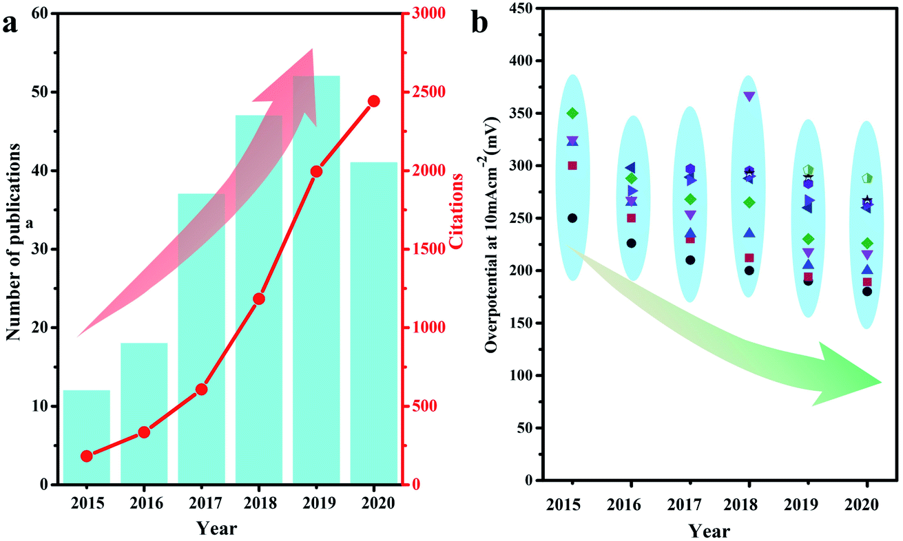 | ||
| Fig. 1 (a) Number of publications and relevant citations during 2015–2020, which were obtained by searching the keywords of “NiFe alloy electrocatalyst” in Web of Science. (b) Evolution of the overpotential required to reach a current density of 10 mA cm−2 on typical NiFe alloy electrocatalysts in 2015–2020. | ||
2. Intrinsic activity optimization
Generally, the optimization of the crystal structure and composition of NiFe alloy electrocatalysts aims at enhancing the intrinsic catalytic efficiencies of their active sites.36 The first significant task is determining the actual active species of NiFe alloys for OER catalysis and the second is to modify their active sites. Designing disordered amorphous phases, metastable phases with high energy, foreign atom in metal alloy systems and in situ formation of oxyhydroxides on the NiFe alloy surface usually result in surprising improvements in catalytic activity. The reason for this is that the modification of the electronic or geometric structures leads to a shift in the bonding energy toward the adsorption/desorption of the OER intermediates on the catalyst surface. Hence, initially, we focus the optimization of the intrinsic activity of NiFe alloys toward OER catalysis via phase construction (including amorphous and metastable crystal phases), foreign atom doping (including metal atom doping and nonmetallic atom combination) and in situ formation of oxyhydroxides for the improvement of their electrochemical performance.2.1 Crystal structure modulation
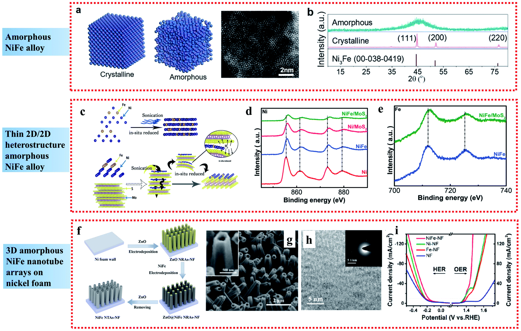 | ||
| Fig. 2 Examples of amorphous NiFe alloy applied in the OER: (a) Atomic model of crystalline and amorphous structures and HAADF-STEM images of the amorphous NiFe alloy catalyst. (b) XRD patterns of NiFe alloy catalysts with different crystalline nature. Reproduced from ref. 40 with permission from the American Chemical Society, Copyright 2020. (c) Schematic of the synthetic process. (d and e) High-resolution Ni and Fe XPS spectra of NiFe/MoS2 2D-on-2D heterostructure sheets. Reproduced from ref. 41 with permission from John Wiley and Sons, Copyright 2019. (f) Illustration of the fabrication process. (g and h) SEM and TEM images, respectively, and (i) steady-state polarization curves of NiFe NTAs–NF electrocatalysts. Reproduced from ref. 42 with permission from the American Chemical Society, Copyright 2018. | ||
Besides single amorphous NiFe alloy nanoparticles, compounding amorphous NiFe alloys with other materials can further increase the number of active sites. 2D nanomaterials exhibit unique properties and have received wide attention as high performance electrocatalysts. Wang et al. presented a self-assembly route on the inert base of 2D materials to construct highly disordered amorphous NiFe/MoS2 heterostructure materials, which exhibited extraordinary electrocatalytic performances towards the OER in alkaline media (Fig. 2c).41 The superior OER activity of the highly disordered amorphous NiFe/MoS2 materials was attributed to two aspects. Firstly, the highly disordered amorphous NiFe alloy could expose a great number of active sites and suppress the aggregation of the active sites, leading to the comparable OER performances to commercial RuO2. Secondly, according to the XPS analyses (Fig. 2d and e), the amorphous NiFe alloy showed strong electronic interaction with the support MoS2, resulting in the beneficial modification of surface electronic structure, which reduced the free energy for adsorption of the intermediates, and thus enhanced the catalytic performances.
In comparison to nanoparticles and 2D materials, 3D amorphous NiFe nanostructured electrodes have also attracted great interest. By combining a 3D nanostructure and amorphous NiFe phase, amorphous NiFe nanotube arrays were fabricated on nickel foam (NiFe NTAs–NF) through electrodeposition and demonstrated to be a high-performance bifunctional electrocatalyst for overall water splitting with low overpotentials of 216 mV for OER at 50 mA cm−2 and 181 mV for the HER at 10 mA cm−2 (Fig. 2f–i).42 The high catalytic activity of the amorphous NiFe NTAs–NF can be contributed to the synergistic effect resulted from the strong electron interactions between Ni and Fe, which led to the creation of more active sites and more efficient mass and charge transport capability. Also, it can be further contributed to the amorphous nature of the NiFe nanotubes, which increased the density of active sites due to the short-range order, improved the charge-transfer rate by providing easy pathways for charges and made the NiFe nanotubes more durable to the structural tension occurring in water splitting due to their higher structural flexibility than crystalline structures.
Briefly, the short-range order of amorphous materials can increase the density of active sites due to their abundant randomly oriented bonds compared to crystalline structures, and the structural flexibility of amorphous materials can endow greater durability in the water splitting process, leading to enhanced electrocatalytic performances for the OER.43–45
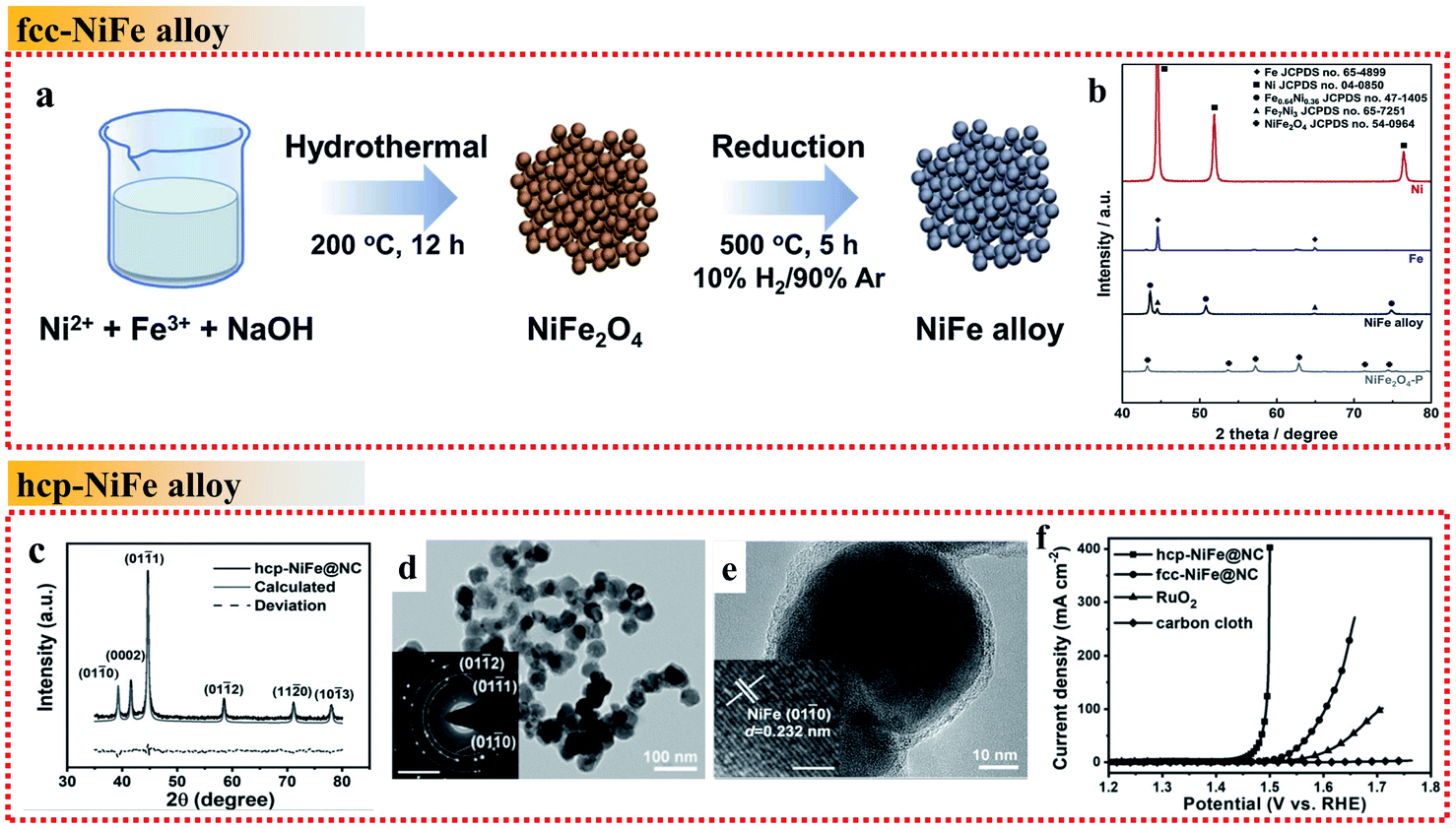 | ||
| Fig. 3 Examples of NiFe alloys with different crystal phases in the OER. (a) Schematic illustration of the fcc NiFe alloy fabrication process. (b) XRD patterns of Ni, Fe, fcc NiFe alloy and NiFe2O4. Reproduced from ref. 48 with permission from Elsevier, Copyright 2019. (c) XRD pattern. (d and e) TEM images. The inset of (d) shows the SAED pattern, scale bar is 5 nm−1. The inset of (e) shows the HRTEM image, scale bar: 2 nm. (f) OER polarization curves recorded on different electrodes. Reproduced from ref. 51 with permission from John Wiley and Sons, Copyright 2019. | ||
Commonly, the synthesized NiFe alloys are typical fcc phase due to its stability. It is difficult to obtain unusual NiFe phases such as the hcp phase, which highlights a new strategy to develop optimized OER catalysts. Wang et al. proposed a simple strategy by controlling the annealing temperature to obtain hcp-phase NiFe NPs encapsulated in an N-doped carbon (NC) shell (hcp-NiFe@NC) instead of fcc-NiFe@NC (Fig. 3c–e).51 The hcp-NiFe@NC catalyst delivered significant OER activity with an unexpectedly low overpotential of 226 mV at 10 mA cm−2, which was 66 mV lower than that of fcc-NiFe@NC in 1.0 M KOH electrolyte (Fig. 3f). The two samples showed almost the same structural characteristics including morphology, size, BET surface area, Raman spectra and N-doping content, and thus their significant difference in OER activity mainly originated in the different phases of NiFe alloy nanoparticles. It was evidenced that the carbon shell encapsulating the NiFe nanoparticles provides direct active sites. Its surface electronic state can be tuned with an increase in the density of states near the Fermi level by the penetration of metal electrons, which can facilitate the catalytic activity. Thus, the modulation of the electronic structure of the NiFe alloy metal core can optimize the OER activity of metal@NC catalysts. In this case, the crystal structure and electronic property of the hcp-phase NiFe alloys are quite different from that of their fcc counterparts. They are more favorable to tailor the external NC electronic state to achieve superior OER activity than fcc-phase NiFe alloys, arising from the unusual intrinsic crystal structure and electronic property.
Briefly, as mentioned above, the stacking mode of the metal atoms in crystals results in distinct crystal structures and electronic properties, which greatly influence the intrinsic catalytic properties of metal alloys. Thus, crystal phase modulation of NiFe metal alloys provides a potential strategy for the enhancement of their OER activity.
2.2 Heteroatomic doping
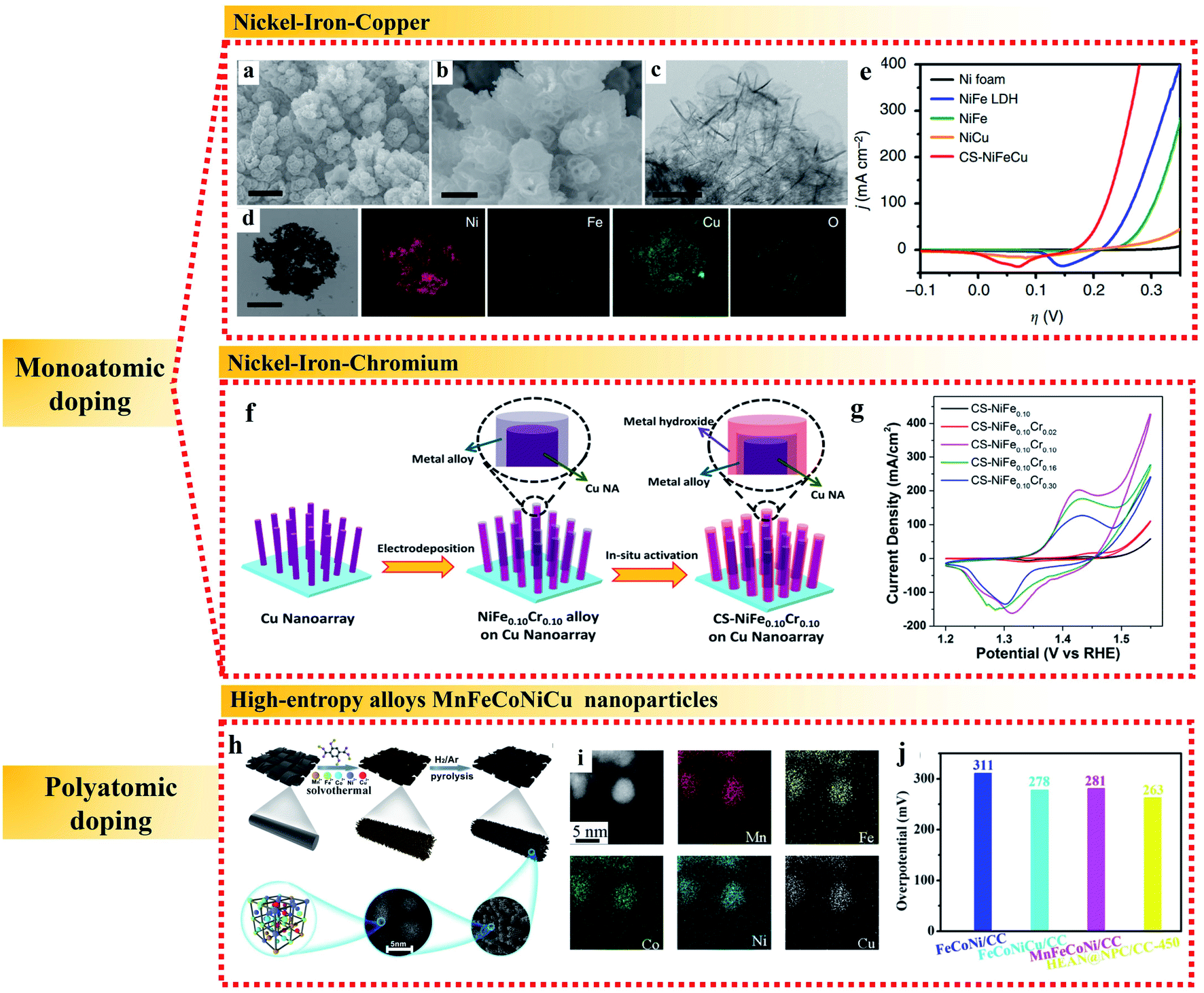 | ||
| Fig. 4 Examples of metallic heteroatomic doping of NiFe alloy applied in the OER. (a and b) SEM images. (c) TEM image. (d) TEM image and corresponding elemental mappings and (e) polarization curves of CS-NiFeCu catalyst on nickel foam. Reproduced from ref. 61 with permission from Nature Publishing Group, Copyright 2018. (f) Schematic process and (g) cyclic voltammograms at 100 mV s−1 of the synthesis of CS-NiFe0.10Crx samples. Reproduced from ref. 62 with permission from the American Chemical Society, Copyright 2018. (h) Schematic illustration, (i) elemental analysis and (j) overpotentials at 10 mA cm−2 of HEA N@NPC/CC. Reproduced from ref. 66 with permission from the Royal Society of Chemistry, Copyright 2020. | ||
In addition to monoatomic doping, high entropy alloys (HEAs) containing five or more near-equimolar elements have attracted great interest as catalytic materials in the past several years.63–65 In HEAs, the atomic size of each component is different, which can cause lattice distortion, and the presence of multiple components is conducive to promote the formation of the solid solution phase and inhibit the movement of dislocations, both of which are beneficial for an enhancement in electrocatalytic activity. As an example, Huang et al. used a one-step solvothermal method to grow a freestanding nanorod-shaped precursor of quinary metal–organic frameworks (i.e., MnFeCoNiCu HEAN MOFs) on the surface of carbon cloth, followed by a high temperature pyrolysis process to form multi-metal high entropy MnFeCoNiCu alloys (Fig. 4h and i).66 The high-entropy MnFeCoNiCu alloys contained highly deformed lattices and various defects, such as dislocations, twins and stacking faults, which led to high surface tension and substantial reduction of the overpotential for the OER to 263 mV at 10 mA cm−2 with a very low Tafel slope of 43 mV dec−1 (Fig. 4j). The remarkable electroactivity of HEAs in the OER can be further attributed to the synergistic effect of each element for efficient electron transfer. The suitable electronic environment of HEAs realizes multi-active sites for the appropriate adsorption of key intermediates and efficient electron transfer during electrocatalysis, which maximize the utilization of surface electroactivity. Thus, high entropy alloys have become a potential platform to discover new alloys with outstanding electrocatalytic activities.
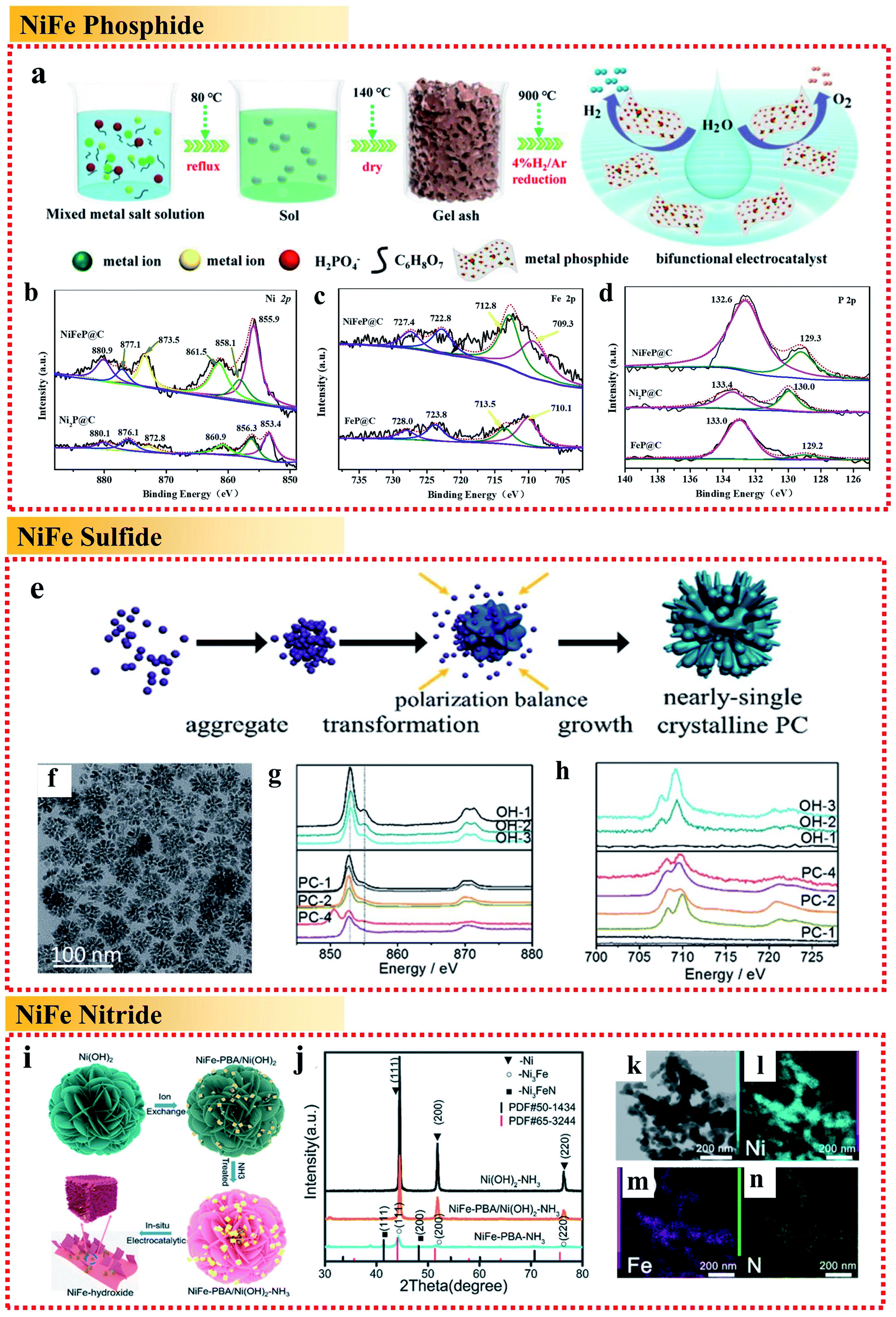 | ||
| Fig. 5 Examples of non-metallic heteroatomic combinations of NiFe alloy applied in the OER. (a) Schematic illustration and (b–d) high-resolution XPS spectra of Ni 2p, Fe 2p and P 2p of metal phosphide@C, respectively. Reproduced from ref. 68 with permission from the American Chemical Society, Copyright 2020. (e) Schematic illustration. (f) TEM image. (g) Ni L-edge sXAS spectra and (h) Fe L-edge sXAS spectra of (NiFe)S2 pyrite mesocrystals. Reproduced from ref. 69 with permission from the Royal Society of Chemistry, Copyright 2018. (i) Schematic illustration, (j) XRD patterns and (k–n) STEM image and EDX mappings of Fe, Ni and N of the Ni3FeN/Ni heterojunction, respectively. Reproduced from ref. 70 with permission from the Royal Society of Chemistry, Copyright 2020. | ||
Besides the combination of NiFe with P, Ni et al. fabricated (NiFe)S2 pyrite mesocrystals in the form of nearly single crystalline porous cubes (Fig. 5e and f).69 The obtained (NiFe)S2 pyrite mesocrystals showed a great OER performance with an overpotential of less than 260 mV to reach a current density of 10 mA cm−2. It was illustrated that the high valence metal cations under the OER conditions are the active centers. The sXAS spectra demonstrated that the existence of S can assist the formation of high valence Ni under the OER conditions (Fig. 5g and h) to improve the OER activity, while Fe can help to stabilize the S doping. The combination with S reduces the Gibbs free energy for the formation of high valence states of Ni and Fe, and directly influences the reaction pathways, resulting in an enhancement in OER performances.
Wang et al. demonstrated a novel in situ chemical etching process of Ni(OH)2 nanosheets followed by a thermal ammonolysis process to fabricate iron–nickel nitride Ni3FeN supported by pure Ni metal (Fig. 5i–n).70 Ni3FeN is not stable, and thus would be converted partially into NiFeOOH under oxygen evolution conditions, forming an NiFeOOH/Ni3FeN/Ni heterojunction and showing extraordinarily high activity for the OER in alkaline medium with a very low overpotential of 200 mV at 10 mA cm−2 and a low Tafel slope of 36 mV dec−1. The result showed that combining NiFe alloys with nitrogen to form the Ni3FeN/Ni metal nitrides was beneficial for increasing the charge transfer dramatically, resulting in faster charge-carrier transportation and better electronic conductivity.
Here, we summarize the effects of doping different heteroatoms in NiFe alloys. When doping NiFe alloys with metallic heteroatoms, the metallic heteroatoms may generally provide new active sites and a synergistic effect with nickel and iron atoms to improve the OER catalytic activity. When NiFe alloys are combined with non-metallic heteroatoms, the catalytic site is still the center of NiFe, but the presence of non-metallic heteroatoms tunes the electronic structure around Ni and Fe, which is beneficial to accelerate the charge transport process and increase the average oxidation state of Ni in the composites, thereby promote the water oxidation reaction. Among the heteroatomic doping alloys, high-entropy alloys (HEAs) together with the composition tailoring and the disordered configuration to provide optimal surface absorption energies for catalysis may be the most potential electrocatalysts with excellent OER performances.
2.3 In situ formation of oxyhydroxides on NiFe alloy surface
Several studies regarding the origin of the activity for the OER have suggested that the in situ generation of oxy-hydroxides (MOOH) after self-reconstruction on the surface under the OER conditions is crucial for the high catalytic activities. Typically, the fast formation of NiOOH in NiFe-based catalysts is most likely dominant during self-reconstruction.71 As early as the 1980s, Corrigan et al. first studied the oxygen evolution behavior of nickel oxide electrodes with Fe impurities. The Fe impurities from the electrolyte co-precipitated on nickel oxide films were discovered to have strong effects on catalyzing the OER. Changing the Fe content could adjust the electrochemical oxidation of Ni(OH)2 to NiOOH process, and a composite NiFe hydroxide with >10% Fe showed intriguing activities toward OER electrocatalysis with an overpotential of ∼200–250 mV at 10 mA cm−2 and a low Tafel slope of 20–25 mV dec−1.72,73 Besides, Stahl's group used operando Mössbauer spectroscopy to provide direct evidence for the formation of FeOOH in the NiFe hydroxide catalyst under steady-state water oxidation conditions.74 A recent study suggested that FeOOH nanoparticles (NPs) could greatly enhance the OER catalytic performance of NiFe LDH through strong interfacial interactions, which could facilitate the oxidation of Ni2+ in the NiFe LDH to enhance its electrochemical catalytic behavior.75 It is worth noting that the in situ generation of oxy-hydroxides (MOOH) after self-reconstruction in the NiFe-based catalyst not only happened on the NiFe oxide, NiFe hydroxides and NiFe LDH, but also on NiFe alloy catalysts. For example, Liang et al. fabricated robust NixFe1−x alloy (core)-ultrathin amorphous oxyhydroxide (shell) nanowire arrays (denoted as NixFe1−x-AHNAs) via a one-step chemical deposition method with the assistance of a magnetic field (Fig. 6a and b).76 Specifically, the amorphous layer on the surface of NixFe1−x alloy nanowires could be formed in situ as an NixFe1−x oxyhydroxide, which resulted from the inevitable oxidation of the nanowires under the alkaline preparation conditions. The NixFe1−x-AHNA electrocatalyst achieved ultralow overpotentials of 248 and 258 mV to reach large current densities of 500 and 1000 mA cm−2 with a small Tafel slope of 34.7 mV dec−1 and excellent stability over 120 h, respectively. In the NixFe1−x-AHNA electrocatalyst, the core NiFe nanowires with the crystalline metallic phase can act as good electron conductors to offer catalysts good conductivity. On the nanowire surface, the in situ-formed amorphous NiFe oxyhydroxide layer has an ultrathin structure (1–5 nm), which is much thinner than that of the NiFe oxyhydroxide prepared via electrodeposition, hydrothermal or chemical deposition methods. The thin nature of the in situ-formed amorphous NiFe oxyhydroxide layer can reduce the transfer resistance of electrons in the catalysts, benefit for the binding promotion of OH−, and thus enhance the catalytic activities (Fig. 6c–e).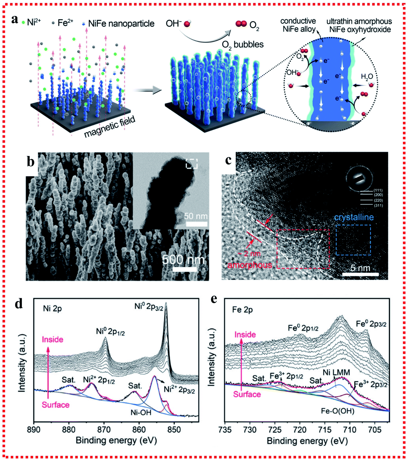 | ||
| Fig. 6 Example for the in situ oxyhydroxide formation on NiFe alloy surface applied in the OER. (a) Schematic of the synthetic process. (b) SEM image with TEM image in the inset. (c) HRTEM image and (d and e) Ni 2p3/2 and Fe 2p3/2 XPS spectra of the NixFe1−x-AHNA nanowire array. Reproduced from ref. 76 with permission from the Royal Society of Chemistry, Copyright 2020. | ||
A similar case was reported by Yu et al., who fabricated a three-dimensional core–shell metal nitride catalyst consisting of NiFeN nanoparticles uniformly decorated on NiMoN nanorods supported on Ni foam, which served as an exceptionally active and durable oxygen evolution reaction catalyst for alkaline seawater electrolysis.77 The in situ Raman spectroscopy technique confirmed the in situ-formed NiFe oxides/oxy(hydroxides) on the surface of NiMoN@NiFeN, which undergoes rapid self-reconstruction due to the partial dissolution of FeOOH in KOH solution and formed amorphous NiOOH nanoarrays with a small amount of FeOOH nanoparticles after the OER. Notably, the in situ-generated amorphous NiFe oxide and NiFe oxy(hydroxide) layers also played a positive role in improving the resistance to corrosion by chloride anions in seawater, which contributed to the superior stability during seawater electrolysis.
Briefly, the in situ generation of oxy-hydroxides (MOOH) after self-reconstruction on the surface of NiFe alloy catalysts under OER conditions or preparation conditions provides a potential strategy to improve the intrinsic catalytic activities of NiFe alloys.
3. Structure optimization
It is well known that the performance of an electrocatalyst is determined not only by its intrinsic activity, but also the number of accessible active sites. The latter depends heavily on the dimensions, geometry, and structure of the electrocatalyst. The morphology of the catalyst such as spheres,78 nanosheet,79 nanorods,80 nanowires,81 and nanoboxes82 plays a significant role in increasing the number of active sites to enhance its electrocatalytic performances. Compared with zero-, one-, and two-dimensional structures, the three-dimensional porous architecture can provide highly desirable properties and is propitious to improve the OER catalytic performance considering that it can offer a large surface area, create numerous fast channels for mass transfer and ion diffusion, and increase the active sites. To the best of our knowledge, downsizing NiFe alloy NPs with well-controlled mono-dispersity is one of the most effective ways to realize an increase in the number of active sites. Maximizing the utilization of each active site through the reasonable design of the NiFe alloy structure is envisioned as a prominent but somewhat difficult approach in developing the utmost efficient NiFe alloys for OER catalysis.3.1 Morphology optimization
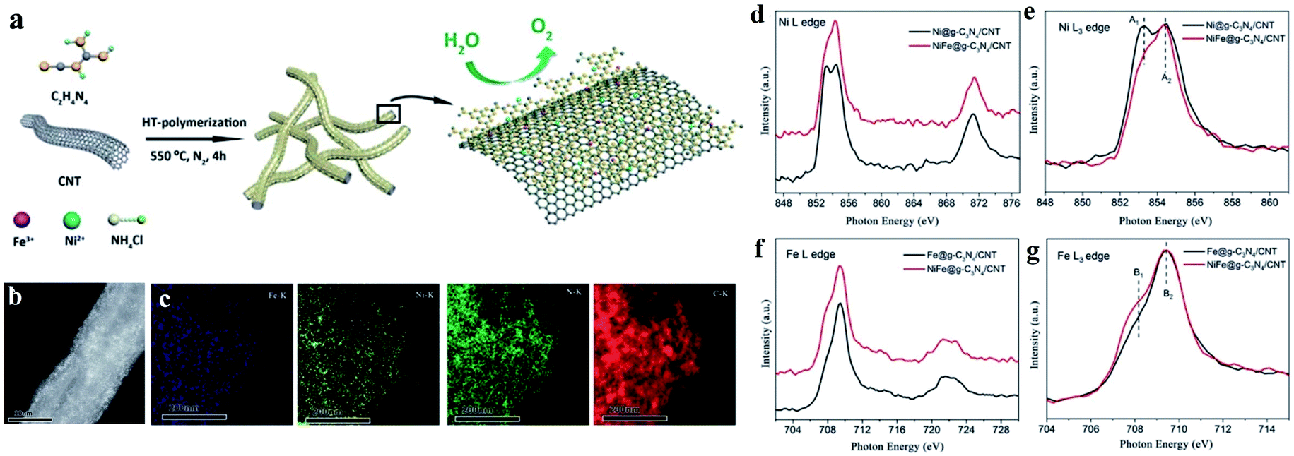 | ||
| Fig. 7 Example of dual Ni/Fe single-atom catalyst applied in the OER. (a) Schematic illustration of the synthetic process, (b) HAADF-STEM images, (c) EDS-mapping, (d) XANES spectra of Ni L edge, (e) enlarged L3 edge spectra in (d), (f) XANES spectra of Fe L edge and (g) enlarged L3 edge in (f) of NiFe@g-C3N4/CNTs. Reproduced from ref. 86 with permission from the Royal Society of Chemistry, Copyright 2018. | ||
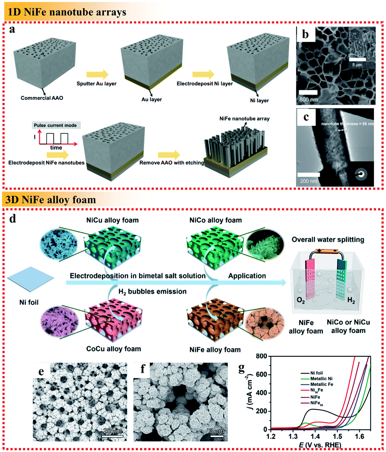 | ||
| Fig. 8 Examples of dimensional control of NiFe alloys applied in the OER. (a) Schematic fabrication process, (b) top-view SEM image with the side-view SEM image as the inset and (c) TEM image with the corresponding SAED pattern as the inset of the NiFe alloy nanotube arrays. Reproduced from ref. 88 with permission from the American Chemical Society, Copyright 2019. (d) Fabrication process of the electrocatalysts, (e and f) SEM images of NiFe foam deposited at 4 A cm−2 for 3 min and (g) OER polarization curves of different samples in 1 M KOH. Reproduced from ref. 90 with permission from the American Chemical Society, Copyright 2019. | ||
3.2 Carbon material modification
On one hand, because the large and rough surface of NiFe alloys is directly exposed to the electrochemical environment, their stability needs to be further improved. Accordingly, coating NiFe alloys with an inert layer such as carbon can avoid direct contact to protect the active NiFe alloys. On the other hand, NiFe alloy nanoparticles easily aggregate, reducing their electroconductibility. Thus, it is an effective strategy to support NiFe alloys on a conductive material to avoid their aggregation and increase their electroconductibility. The different ways to support NiFe alloys on conductive materials are shown in Fig. 9, including NiFe@carbon, NiFe on graphene, NiFe on carbon nanotubes, NiFe on carbon fibers, NiFe on MOF-derived carbon, and NiFe on biomass-derived carbon. Furthermore, the different ways for supporting NiFe alloys on conductive materials result in different catalytic activities.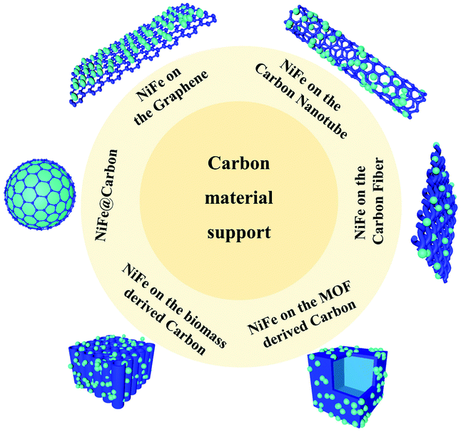 | ||
| Fig. 9 NiFe alloys supported on different conductive substrates. | ||
Here, we begin with the simplest NiFe@C core–shell structure. The core-shelled NiFe@C catalysts, consisting of NiFe nanoparticles with a diameter of 15 nm encapsulated by 2–3 carbon layers, were developed using a one-pot synthetic method by injecting a high-density electrical pulse through NiFe wires with ethanol medium acting as the carbon source (Fig. 10a and b).91 The core-shelled NiFe@C catalyst displayed outstanding catalytic performances for both the OER and HER in alkaline solution. The large number of Fe(III) species on the surface of NiFe@C revealed from the XPS analysis, which can act as a positive charge active region, enhanced the partial charge transfer and generated highly active sites (Fig. 10c and d). More importantly, the carbon layers encapsulating the NiFe alloys promoted the electrochemical stability by protecting the alloy nanoparticles from corrosion and/or oxidization caused by the electrochemical redox process at interface between the catalysts and electrolytes. Furthermore, an ultrathin carbon shell on alloy nanoparticles can facilitate electron penetration from the alloy core to the catalyst surface. This unique property modulates the electronic properties of the carbon surface to more favorably adjust the binding energies of reaction intermediates on the catalyst surface, enhancing the catalytic activities for both the OER and HER.
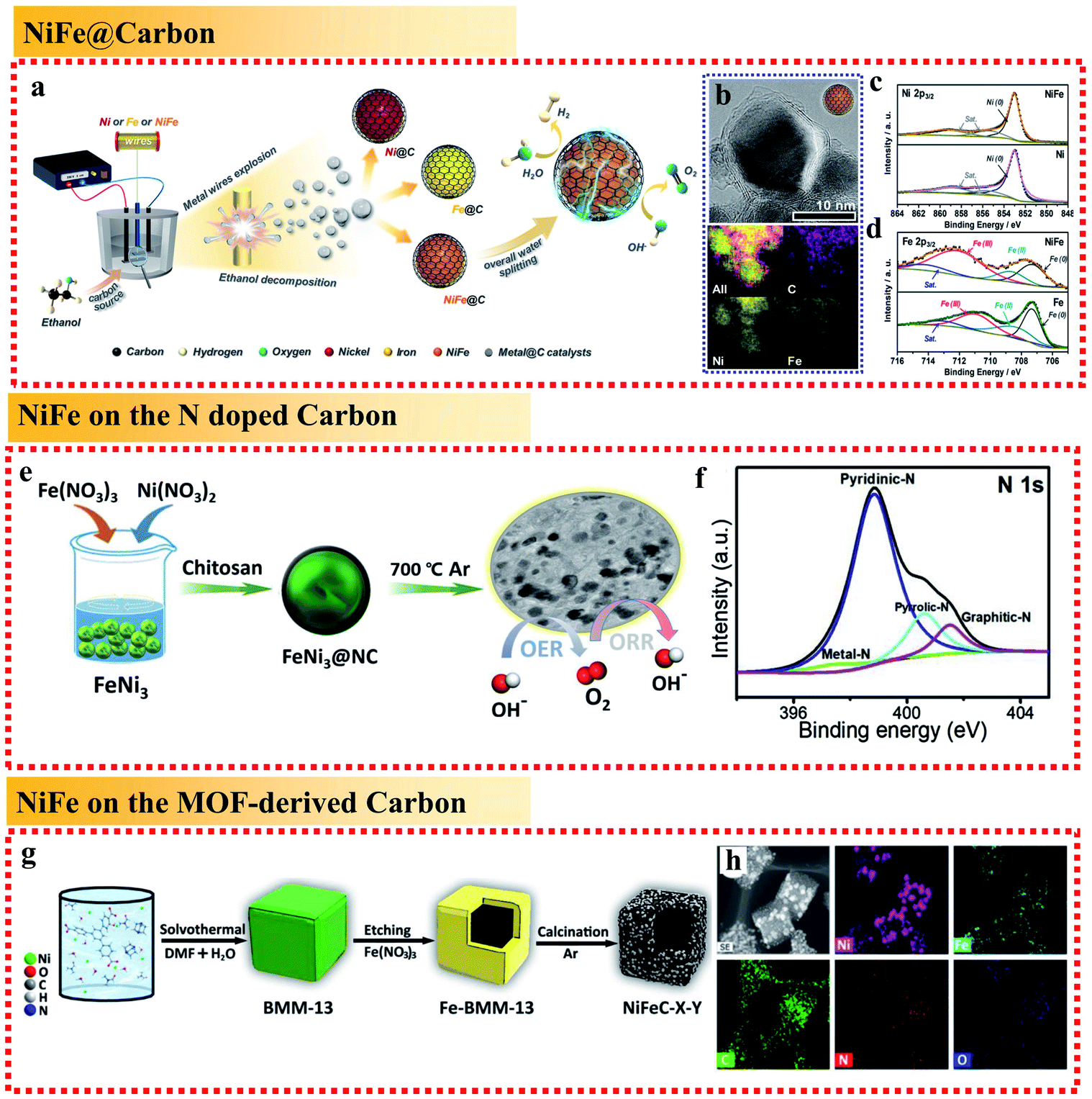 | ||
| Fig. 10 Examples for NiFe alloy-loaded conductive material support applied in the OER. (a) Schematic illustration of the synthetic process. (b) TEM image with corresponding EDS mapping and (c and d) Ni 2p3/2 and Fe 2p3/2 XPS spectra of the NiFe@C nanocomposites. Reproduced from ref. 91 with permission from Elsevier, Copyright 2018. (e) Schematic illustration of the synthetic process and (f) N 1s XPS spectra of FeNi3@NC. Reproduced from ref. 92 with permission from Elsevier, Copyright 2020. (g) Schematic illustration and (h) element mapping images of BMM-13-derived bimetallic FeNi3 nanomaterials (NiFeC–X–Y). Reproduced from ref. 95 with permission from Elsevier, Copyright 2020. | ||
In addition to coating NiFe alloy nanoparticles with carbon layers to form a core–shell structure, the most common way is to support NiFe alloy nanoparticles on layered graphite carbon. For example, Chen et al. synthesized FeNi3 alloy-coupled N-doped carbon (FeNi3@NC) using chitosan as both the nitrogen and carbon source (biomass-derived carbon). The presence of the N-dopant in the carbon layers increased the degree of defects in the catalyst and was beneficial for the OER performances.92 It exhibited a low OER overpotential of 277 mV at 10 mA cm−2 (Fig. 10e). In the electrocatalysts, the presence of NiFe alloys could significantly enhance the electrical conductivity, and thus fasten the charge transfer, while the large amounts of pyri-N in the carbon layers could improve the catalyst conductivity and surface wettability (Fig. 10f). In addition, the co-existence of grap-N in the electrocatalyst also helped to improve the diffusion-limited current density. Thus, the exposed edges of the FeNi3 nanoparticles, the metal–N interface coupling center, and the N–C center all provided active sites and contributed to the excellent electrocatalytic performances. Furthermore, the results also showed that the rational integration of NiFe and carbon layers can exhibit a synergistic effect among the Fe, Ni and NC layers to greatly improve the electrocatalytic activities toward the OER by coordinating their advantages and offsetting their disadvantages.
The cases of NiFe alloys on carbon nanotubes and fibers are similar. NiFe alloy nanoparticles embedded on N-doped carbon nanotubes (NiFe/N–CNT)93 and NiFe alloy nanoparticles anchored on bamboo stick-derived N-doped carbon fibers (NiFe@NCNFs)94 both showed similar active roles to enhance the catalytic OER performances. Firstly, the highly active NiFe alloys are synergistically integrated in the nanocomposites through the bifunctional electronic effect, followed by embedding in the conductive shell, which can suppress the agglomeration and dissolution of the inner NiFe nanoparticles. Secondly, the Ni atoms on the Fe-based alloy nanoparticles afford a moderate binding affinity for oxygen molecules and OH− ions, whereas the electron transfer through the graphitic carbon shell can be also enhanced. Thirdly, the N-doped graphitic carbon shells provide both electrical conductivity and durability during the long-term oxygen catalytic reaction.
The use of MOF-derived carbon to support NiFe alloys has been reported to provide a large surface area with the coexistence of micropores and mesopores inherited from the MOF precursor. Ding et al. designed a three-step route to fabricate a hollow MOF-derived 3D carbonaceous matrix with randomly loaded FeNi3 alloy nanoparticles (Fig. 10g and h).95 The resulting NiFeC composites exhibited great OER performances with a low overpotential of 269 mV at 10 mA cm−2. The good OER activity of NiFeC can be attributed to: (i) the hollow cubic carbon shell with the coexistence of micropores and mesopores in the resultant catalyst provides a large surface area to enable efficient contact between the solid catalyst and the liquid electrolyte and facilitate the diffusion of oxygen and (ii) the porous carbon matrix derived from the MOF can effectively restrict the agglomeration of the NiFe nanoparticles during calcination at high temperature, improve the electron conductivity and facilitate quick electron transfer.
In summary, coating conductive materials on NiFe alloys can avoid their direct contact with the electrolyte and protect the active NiFe alloys from corrosion. It can also prevent NiFe alloys from aggregating and increase their electroconductibility. The conductive material can endow NiFe alloys with both high conductivity and catalytic activity, and the large specific surface area leads to fast electron transfer and ion diffusion and facilitates charge transfer.
3.3 Composite structure
Rationally designing the composite structure of the whole catalytic electrode can enhance the mechanical stability, electron transfer efficiency, ion diffusion rate, reaction kinetics, and exposure of active sites. Nickel foam (NF) with a large surface, 3D structure and high flexibility has emerged as a leading candidate substrate for NiFe alloys. Jin et al. reported a fast one-step method for the electrodeposition of NiFe alloy nanoparticles with NF as the substrate to form a composite electrode.96 To increase the roughness and surface area of the obtained NiFe alloy nanoparticles, Ni and Fe chlorides were used instead of the commonly used Ni and Fe sulfate because the chloridion can prevent passivation to accelerate NiFe deposition by replacing the adsorbed oxygen on the electrode. The as-deposited NiFe/NF could be directly used as OER catalysts without further treatment such as adding binders or conductive film. The Ni 2p3/2 XPS showed that the proportion of Ni3+ and Ni2+ increased after the OER test, while the O 1s spectrum revealed that O existed in the form of OH− and O2−, suggesting the existence of Ni(OH)2 and NiOOH. The synergetic effects of the deposited NiFe alloy and NiFe hydroxides formed during the OER enabled both high conductivity and catalytic activity. The large specific surface area due to the 3D skeleton of NF led to fast electron transfer and ion diffusion and the porous structure exposed with more active sites facilitated the charge transfer.In addition, depositing NiFe alloy NPs on conductive and catalytically active substrates to form a composite structure is also an effective strategy to improve their catalytic performances. Xu et al. developed a top-down method to anchor NiFe alloy nanoparticles on the surface of hierarchical nanoporous V2O3 nanosheets (Fig. 11a–d).97 The NiFe@V2O3 hybrid exhibited excellent electrocatalytic performances for both the OER and HER. When employed as a bifunctional electrode for overall water splitting, NiFe@V2O3 only required a cell voltage of 1.56 V to reach 10 mA cm−2 (Fig. 11e). The reason for the excellent electrocatalytic performances is that the designed hierarchical nanoporous structure enhanced the specific surface areas and facilitated the mass transfer of the electrolytes and the evolved gases. Moreover, the catalytically active metallic-like V2O3 matrix could accelerate electron transfer and provide extra active sites for electrocatalysis.
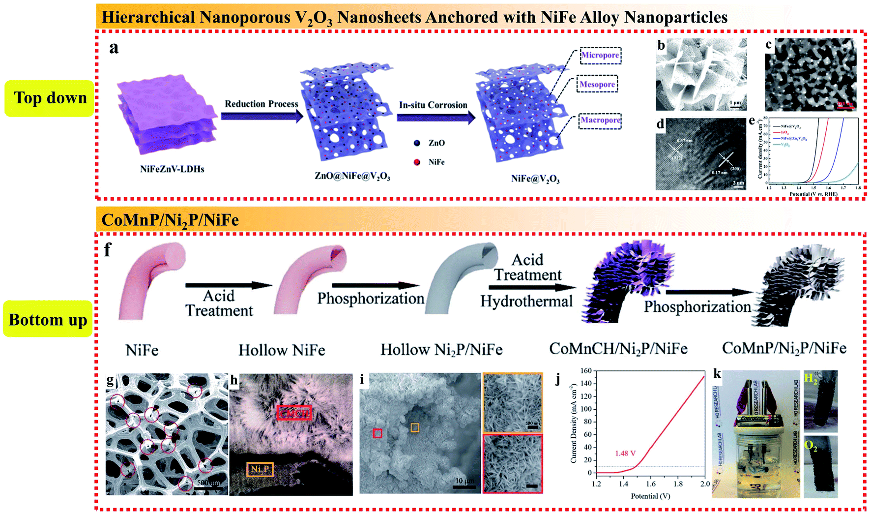 | ||
| Fig. 11 (a) Synthetic strategy, (b–d) SEM, TEM and HRTEM images, respectively, and (e) OER polarization curves of the 3D hierarchical nanoporous NiFe@V2O3. Reproduced from ref. 97 with permission from the American Chemical Society, Copyright 2019. (f) Schematic illustration of the synthetic process, (g) SEM image of Ni2P after acid treatment of the CoMnP/Ni2P/NiFe electrocatalyst, (h) SEM image of the cross-section of Ni2P/CoMnCH, (i) SEM image of Ni2P/CoMnP on NiFe foam and the magnified areas of the orange and red regions, (j) LSV curves of overall water splitting in the two-electrode configuration, and (k) digital photo of the overall water splitting setup driven by a 1.5 V battery. Reproduced from ref. 98 with permission from the Royal Society of Chemistry, Copyright 2019. | ||
Bu et al. prepared a unique sandwich structure of CoMnP/Ni2P/NiFe by introducing an Ni2P interlayer between CoMnP nanosheets and nickel–iron (NiFe) foam to achieve an excellent bifunctional electrocatalyst in alkaline media (Fig. 11f).98 It was notable that the hollow 3D NiFe alloy substrate provided a high loading capacity of CoMnP nanosheets, while the continuous low-resistant Ni2P interlayer between the NiFe substrate and the CoMnP active material yielded an efficient electron transmission channel from the current collector to the active materials (Fig. 11g–i). In addition, the introduction of Ni2P could modify the electronic structure of CoMnP via strong electron interaction and enhance the contact between CoMnP and NiFe. Importantly, the synergistic effect of combining surface and interface engineering in this unique sandwich structure resulted in remarkable OER and HER performances, which was proven using a 1.5 V battery to power an overall water splitting device (Fig. 11j and k). The high bifunctional activity is mainly attributed to the structural design, interface and surface engineering as follows: (i) the 3D hollow NiFe foam provides sufficient loading capacity for the CoMnP nanosheets, which enhances the exposure of active sites; (ii) the Ni2P sublayer between CoMnP and NiFe foam provides rapid electron pathways to increase the electron transfer; and (iii) the electronic structure of the active sites on the CoMnP nanosheets is modified by Ni2P via strong electron interaction, thus improving the intrinsic activity of the surface active species.
In summary, according to the description mentioned above, the composite structure of NiFe alloys with other substances not only can use the active sites of the dual component, but the composite structure of the whole catalytic electrode can also elevate the electron transfer efficiency, ion diffusion rate, reaction kinetics, exposure of active sites and mechanical stability, and thus has a great impact to improve the OER performances.
4. Conclusions and perspective
The development and use of hydrogen energy is a practical and significant approach for solving various issues associated with the continuous consumption of traditional fuel energy. To date, researchers have focused great interest on water splitting devices for the large-scale and green production of hydrogen. However, water-splitting is not a particularly efficient technique due to the high energy barrier in the OER process; therefore, designing superior OER catalysts plays a crucial role in water splitting devices. Specifically, NiFe-based materials as OER electrocatalysts have shown excellent performances compared to noble metal-based OER electrocatalysts. Different from other reviews related to NiFe-based catalysts, the present review emphasized the mechanism of NiFe alloy catalysts in alkaline water oxidation and their catalytic active centers.In this review, based on numerous experimental and theoretical reports, the mechanism of the OER on NiFe alloy catalysts was discussed in depth to emphasize the active roles of NiFe alloy catalysts, suggesting that NiFe alloy catalysts can be promising candidates to achieve optimal adsorption for OER intermediates to enhance the OER activities by electronic modulation and structural design (Fig. 12, Tables 1 and 2). Four types of effective means were proposed to increase their intrinsic activity by electronic modulation as follows: (i) preparing an amorphous phase with short-range order but long-range disorder of NiFe alloys can improve the charge transfer rate by providing easy pathways for charges. (ii) Acquiring the metastable phase of NiFe alloys, which possesses a high energy density and gives rise to distinct electronic states to expose more active sites. (iii) Controllably doping multiple heteroatoms to form high-entropy alloys with high complexity and multiple components can provide more active sites and lead to the effective modulation of the electronic configuration and intrinsically promote the OER kinetics. (iv) Catalyst design to achieve the in situ generation of oxy-hydroxides (MOOH) after self-reconstruction on the surface of NiFe alloys under OER or preparation conditions, which play a crucial active role due to their high catalytic activities and can reduce the transfer resistance of electrons within catalysts. This is also beneficial for the binding promotion of OH−, and thus the enhancement of the catalytic activities. Meanwhile, four types of effective means are also proposed to increase the number of actives sites by structural design as follows: (v) constructing dual-metal single atoms can expose excess metal active sites, good electrical contact and partial charge transfer between the Fe and Ni sites. (vi) Constructing specific nanostructures of NiFe alloys can increase the surface density of active sites. (vii) Employing carbon materials as a support can promote the transportation of ions and electrons. (viii) Composite structures can take advantage of all the composite compositions and structures to form a composite catalytic electrode, which can enhance the mechanical stability, electron transfer efficiency, ion diffusion rate, reaction kinetics, and exposure of active sites.
 | ||
| Fig. 12 Illustration of the electronic modulation and structural design of NiFe alloy electrocatalysts toward efficient OER. | ||
| Composition optimization | Active roles | Electrocatalyst | Electrolyte | η OER (mV) | Tafel slope (mV dec−1) | Ref. |
|---|---|---|---|---|---|---|
| Amorphous NiFe alloy | The short-range atomic ordering but long-range disordered structure could increase the active site density, thus improving the charge-transfer rate by providing easy pathways for charges | Amorphous NiFe | 1 M KOH | 265 | 24 | 40 |
| NiFeIrx/Ni NW@NSs | 1 M KOH | 200 | 44.6 | 99 | ||
| NiFe NTAs–NF | 1 M KOH | 216 | 64.5 | 42 | ||
| Metastable NiFe phase | The stacking mode of NiFe metal atoms in different crystal phases gives rise to distinct structures and electronic properties, greatly influencing the intrinsic catalytic properties of NiFe metal alloy nanomaterials. The metastable hcp-phase NiFe possesses favorable electronic properties to expedite the OER reaction | Fcc-phase NiFe alloy | 1 M KOH | 298 | 51.9 | 48 |
| Hcp-phase NiFe alloy | 1 M KOH | 226 | 41 | 51 | ||
| Metallic heteroatomic doping | The introduction of another metal heteroatom can act as active sites and can further modify the surface electron distribution of a metal or alloy to produce more active sites | FeCoNi | 1 M KOH | 288 | 60 | 100 |
| NiFeCu | 1 M KOH | 180 | 33 | 61 | ||
| NiFeCr | 1 M KOH | 200 | 28 | 62 | ||
| High entropy alloys MnFeCoNiCu | 1 M KOH | 263 | 43 | 66 | ||
| Nonmetallic heteroatomic combination | The combination of a non-metallic heteroatom with NiFe tunes the electronic structure around Ni and Fe, which is beneficial to accelerate the charge transport process, resulting in an increase in the average oxidation state of metals, and thereby promote the water oxidation reaction | NiFe phosphide | 1 M KOH | 260 | 38.7 | 68 |
| NiFe diselenide | 1 M KOH | 267 | 67 | 103 | ||
| NiFe nitride | 1 M KOH | 200 | 36 | 70 | ||
| In situ formation of oxyhydroxide on NiFe alloy | The in situ generation of oxy-hydroxides (MOOH) after self-reconstruction on the surface under OER conditions is crucial active role for the OER | NixFe1−x-AHNAs | 1 M KOH | 248 at 500 mA cm−2 | 34.7 | 76 |
| NiMoN@NiFeN | 1 M KOH | 248 at 100 mA cm−2 | 58.6 | 77 |
| Structure optimization | Active roles | Electrocatalyst | Electrolyte | η OER (mV) | Tafel slope (mV dec−1) | Ref. |
|---|---|---|---|---|---|---|
| Single-atom conception | The dual-metal atoms stabilized by nitrogen or oxygen bridges can present excess metal active sites, good electrical contact and partial charge transfer between the Fe and Ni sites and facilitate the adsorption and dissociation of the reaction intermediates to promote the OER | HG–NiFe | 1 M KOH | 310 | 39 | 84 |
| Bimetallic FeNi | 0.1 M KOH | 430 | 56 | 85 | ||
| NiFe@g-C3N4/CNT | 1 M KOH | 326 | 67 | 86 | ||
| Dimensions control | Dimensional control of NiFe alloys is a potential way to provide high surface area, promote fast guided charge transport and mass transfer and accelerate the dissipation of gas bubbles to enhance the OER performance | 1D NiFe alloy nanotube array | 1 M KOH | 236 | 45 | 88 |
| 3D NiFe alloy foams | 1 M KOH | 240 | 47 | 90 | ||
| Carbon material support | Coating conductive materials on the NiFe alloys can avoid the direct contact of NiFe alloys with the electrolyte and protect active NiFe alloys from corrosion. It can also prevent NiFe alloys from aggregating and increase their electroconductibility. The conductive material can provide NiFe alloys with both high conductivity and catalytic activity and the large specific surface area leads to fast electron transfer and ion diffusion and facilitates charge transfer | NiFe@C | 1 M KOH | 345 | 57 | 91 |
| Ni0.5Fe0.5@N-graphite | 1 M KOH | 210 | 62 | 101 | ||
| Ni50Fe50@N–CNTs | 1 M KOH | 318 | 79 | 102 | ||
| FeNi3@NC | 1 M KOH | 277 | 77 | 92 | ||
| NiFe@NCNFs | 1 M KOH | 294 | 52 | 94 | ||
| NiFeC-800-5 | 1 M KOH | 269 | 72 | 95 | ||
| Composite structure | The composite structure of NiFe alloy with other substances not only can use the active site of the dual component, but also the composite structure of the whole catalytic electrode can enhance the electron transfer efficiency, ion diffusion rate, reaction kinetics, exposure of active sites and mechanical stability, and thus has a great impact to improve the OER performances | NiFe/NF | 1 M KOH | 191 | 44.1 | 96 |
| NiFe@V2O3 | 1 M KOH | 330 | 51 | 97 | ||
| CoMnP/Ni2P/NiFe | 1 M KOH | 240 at 50 mA cm−2 | 60 | 98 |
Obviously, with the deepening of research and the development of analysis technology, there are still many questions that need to be emphasized. (i) When designing OER catalysts, researchers often tend to focus on decreasing the overpotential, but ignore the stability. Thus, it is highly desirable to fabricate NiFe alloy catalysts with a low overpotential and long-term stability. (ii) The majority of the as-prepared NiFe alloy electrocatalysts only exhibit excellent properties under alkaline conditions as they dissociate easily under acidic conditions. Thus, greater attention should be paid to fabricating NiFe alloy catalysts that can function under universal pH. Meanwhile, designing bifunctional NiFe alloy catalysts for both the OER and the HER can solve the problem of poor compatibility during overall water splitting. (iii) The catalyst phase appears to change during the OER process, and thus in situ characterization techniques, atomic scale characterization techniques and DFT calculations are needed to identify the true active sites present in NiFe alloy materials to dissect the mechanism and reaction pathway for water splitting and the precise structure–activity correlation.
Clearly, NiFe alloy electrocatalysts deserve our continued attention. Combined with various experiments, characterization and DFT calculations, a deeper understanding of the relationship among electronic modulation, structural design and oxygen evolution reaction performance may be achieved. Prospectively, this understanding will provide more opportunities for the rational design of NiFe alloys electrocatalysts and offer insight into the nature of alloys catalysts and NiFe-based catalysts, not only for the OER, HER and ORR, but also for other important catalytic systems.
Conflicts of interest
There are no conflicts to declare.Acknowledgements
This work is supported by the National Natural Science Foundation of China (Grant No. U1832137 and 21871130), a Project funded by the Priority Academic Program Development of Jiangsu Higher Education Institutions and the Postgraduate Research & Practice Innovation Program of Jiangsu Province (KYCX20_0023).References
- W. Li, D. D. Wang, Y. Q. Zhang, L. Tao, T. H. Wang, Y. Q. Zou, Y. Y. Wang, R. Chen and S. Y. Wang, Adv. Mater., 2020, 32, 1907879 CrossRef CAS.
- J. Wang, H. Kong, J. Y. Zhang, Y. Hao, Z. P. Shao and F. Ciucci, Prog. Mater. Sci., 2020, 116, 100717 CrossRef.
- H. Chen, X. Liang, Y. P. Liu, X. Ai, T. Asefa and X. X. Zou, Adv. Mater., 2020, 32, 2002435 CrossRef.
- K. Dong, Y. Lei, H. T. Zhao, J. Liang, P. Ding, Q. Liu, Z. Q. Xu, S. Y. Lu, Q. Li and X. P. Sun, J. Mater. Chem. A, 2020, 8, 23123 RSC.
- C. Feng, M. B. Faheem, J. Fu, Y. Q. Xiao, C. L. Li and Y. B. Li, ACS Catal., 2020, 10, 4019–4047 CrossRef CAS.
- Z. P. Wu, X. F. Lu, S. Q. Zang and X. W. Lou, Adv. Funct. Mater., 2020, 30, 1910274 CrossRef CAS.
- Y. B. Lian, H. Sun, X. B. Wang, P. W. Qi, Q. Q. Mu, Y. J. Chen, J. Ye, X. H. Zhao, Z. Deng and Y. Peng, Chem. Sci., 2019, 10, 464–474 RSC.
- F. S. Zhang, J. W. Wang, J. Luo, R. R. Liu, Z. M. Zhang, C. T. He and T. B. Lu, Chem. Sci., 2018, 9, 1375–1384 RSC.
- L. G. Li, P. T. Wang, Q. Shao and X. Q. Huang, Chem. Soc. Rev., 2020, 49, 3072–3106 RSC.
- Z. J. Chen, X. G. Duan, W. Wei, S. B. Wang and B. J. Ni, Nano Energy, 2020, 78, 105270 CrossRef CAS.
- J. Zhang, Q. Y. Zhang and X. L. Feng, Adv. Mater., 2019, 31, 1808167 CrossRef.
- Q. Shi, C. Z. Zhu, D. Du and Y. H. Lin, Chem. Soc. Rev., 2019, 48, 3181–3192 RSC.
- L. Jiao, Y. X. Zhou and H. L. Jiang, Chem. Sci., 2016, 7, 1690–1695 RSC.
- K. Y. Zhu, F. Shi, X. F. Zhu and W. S. Yang, Nano Energy, 2020, 73, 104761 CrossRef CAS.
- H. F. Wang, L. Y. Chen, H. Pang, S. Kaskel and Q. Xu, Chem. Soc. Rev., 2020, 49, 1414–1448 RSC.
- A. Jain, Z. B. Wang and J. K. Nørskov, ACS Energy Lett., 2019, 4, 1410–1411 CrossRef CAS.
- Z. J. Chen, X. G. Duan, W. Wei, S. B. Wang and B. J. Ni, Nano Energy, 2020, 78, 105392 CrossRef CAS.
- Z. H. Yan, H. H. Liu, Z. M. Hao, M. Yu, X. Chen and J. Chen, Chem. Sci., 2020, 11, 10614–10625 RSC.
- W. Y. Yuan, C. M. Li, M. Zhao, J. Zhang, C. M. Li and S. P. Jiang, Electrochim. Acta, 2020, 342, 136118 CrossRef CAS.
- M. Zhao, W. Y. Yuan and C. M. Li, J. Mater. Chem. A, 2017, 5, 1201–1210 RSC.
- S. Chandrasekaran, D. T. Ma, Y. Q. Ge, L. B. Deng, C. Bowen, J. Roscow, Y. Zhang, Z. Q. Lin, R. D. K. Misra, J. Q. Li, P. X. Zhang and H. Zhang, Nano Energy, 2020, 77, 105080 CrossRef CAS.
- Q. Wang, X. Huang, Z. L. Zhao, M. Y. Wang, B. Xiang, J. Li, Z. X. Feng, H. Xu and M. Gu, J. Am. Chem. Soc., 2020, 142, 7425–7433 CrossRef CAS.
- Y. Q. Li, M. Cui, Z. H. Yin, S. R Chen and T. L. Ma, Chem. Sci., 2020, 11, 11646–11671 RSC.
- Q. Zhang, K. H. Kusada, D. S. Wu, N. K. Ogiwara, T. Yamamoto, T. Toriyama, S. Matsumura, S. Kawaguchi, Y. Kubota, T. Honmae and H. Kitagawa, Chem. Sci., 2019, 10, 5133–5137 RSC.
- M. Zhao, H. L. Li, W. Y. Yuan and C. M. Li, ACS Appl. Energy Mater., 2020, 3, 3966–3977 CrossRef CAS.
- J. Mohammed-Ibrahim, J. Power Sources, 2020, 448, 227375 CrossRef CAS.
- J. Zhao, J. J. Zhang, Z. Y. Li and X. H. Bu, Small, 2020, 16, 2003916 CrossRef CAS.
- F. Dionigi, Z. H Zeng, I. Sinev, T. Merzdorf, S. Deshpande, M. B. Lopez, S. Kunze, I. Zegkinoglou, H. Sarodnik, D. X. Fan, A. Bergmann, J. Drnec, J. F. D Araujo, M. Gliech, D. Teschner, J. Zhu, W. X. Li, J. Greeley, B. R. Cuenya and P. Strasser, Nat. Commun., 2020, 11, 2522 CrossRef CAS.
- H. Liu, D. H. Yang, X. Y. Wang, J. W. Zhang and B. H. Han, J. Colloid Interface Sci., 2021, 581, 362–373 CrossRef CAS.
- F. Ganci, V. Cusumano, P. Livreri, G. Aiello, C. Sunseri and R. Inguanta, Int. J. Hydrogen Energy, 2020, 46, 10082–10092 CrossRef.
- Z. Li, L. Cai, M. Song, Y. C. Shen, X. Wang, J. Li, J. Wang, P. Wang and L. Tian, Electrochim. Acta, 2020, 339, 135886 CrossRef CAS.
- L. Du, L. L. Luo, Z. X. Feng, M. Engelhard, X. H. Xie, B. H. Han, J. M. Sun, J. H. Zhang, G. P. Yin, C. M. Wang, Y. Wang and Y. Y. Shao, Nano Energy, 2017, 39, 245–252 CrossRef CAS.
- K. Y. Zhu, X. F. Zhu and W. S. Yang, Angew. Chem., Int. Ed., 2019, 58, 1252–1265 CrossRef CAS.
- D. Xiang, X. J. Bo, X. H. Gao, C. M. Zhang, C. Du, F. Q. Zheng, Z. H. Zhuang, P. Li, L. D. Zhu and W. Chen, J. Power Sources, 2019, 438, 226988 CrossRef CAS.
- K. Y. Zhu, T. Wu, M. R. Li, R. F. Lu, X. F. Zhu and W. S. Yang, J. Mater. Chem. A, 2017, 5, 19836–19845 RSC.
- T. Wang, X. Zhang, P. Yang and S. P. Jiang, Inorg. Chem. Front., 2020, 7, 3578–3587 RSC.
- L. Yao, Z. B. Geng, W. Zhang, X. F. Wu, J. H. Liu, L. P. Li, X. Y. Wang, X. Y. Hou, K. Xu, K. K. Huang and S. H. Feng, ACS Sustainable Chem. Eng., 2020, 8, 17194–17200 CrossRef CAS.
- F. Hu, H. Y. Wang, Y. Zhang, X. C. Shen, G. H. Zhang, Y. B. Pan, J. T. Miller, K. Wang, S. L. Zhu, X. J. Yang, C. M. Wang, X. J. Wu, Y. J. Xiong and Z. M. Peng, Small, 2019, 15, 1901020 CrossRef.
- L. Zhang, R. Zhang, R. X. Ge, X. Ren, S. Hao, F. Y. Xie, F. L. Qu, Z. Liu, G. Du, A. M. Asiri, Ba. Z. Zheng and X. P. Sun, Chem.–Eur. J., 2017, 23, 11499–11503 CrossRef CAS.
- W. Z. Cai, R. Chen, H. B. Yang, H. B. Tao, H. Y. Wang, J. J. Gao, W. Liu, S. Liu, S. F. Hung and B. Liu, Nano Lett., 2020, 20, 4278–4285 CrossRef CAS.
- Y. Z. Wang, Y. Y. Zhou, M. Z. Han, Y. K. Xi, H. H. You, X. F. Hao, Z. P. Li, J. S. Zhou, D. D. Song, D. Wang and F. M. Gao, Small, 2019, 15, 1805435 CrossRef.
- L. Xu, F. T. Zhang, J. H. Chen, X. Z. Fu, R. Sun and C. P. Wong, ACS Appl. Energy Mater., 2018, 1, 1210–1217 CrossRef CAS.
- S. Wang, X. B. Ge, C. Lv, C. Hu, H. T. Guan, J. Wu, Z. N. Wang, X. H. Yang, Y. Shi, J. F. Song, Z. Zhang, A. Watanabec and J. G. Cai, Nanoscale, 2020, 12, 9557–9568 RSC.
- L. Yu, H. Q. Zhou, J. Y. Sun, I. K. Mishr, D. Luo, F. Yu, Y. Yu, S. Chen and Z. F. Ren, J. Mater. Chem. A, 2018, 6, 13619–13623 RSC.
- S. Anantharaj and S. Noda, Small, 2020, 16, 1905779 CrossRef CAS.
- Z. X. Fan and H. Zhang, Chem. Soc. Rev., 2016, 45, 63–82 RSC.
- Y. C. Yao, D. S. He, Y. Lin, X. Q. Feng, X. Wang, P. Q. Yin, X. Hong, G. Zhou, Y. E. Wu and Y. D. Li, Angew. Chem., Int. Ed., 2016, 55, 5501–5505 CrossRef CAS.
- D. W. Lim, E. Oh, C. Lim, S. E. Shim and S. H. Baeck, Catal. Today, 2020, 352, 27–33 CrossRef.
- Z. W. Gao, J. Y. Liu, X. M. Chen, X. L. Zheng, J. Mao, H. Liu, T. Ma, L. Li, W. C. Wang and X. W. Du, Adv. Mater., 2019, 31, 1804769 CrossRef.
- X. Zhang, Y. F. Zhao, Y. X. Zhao, R. Shi, G. I. N. Waterhouse and T. R. Zhang, Adv. Energy Mater., 2019, 9, 1900881 CrossRef.
- C. H. Wang, H. C. Yang, Y. J. Zhang and Q. B. Wang, Angew. Chem., Int. Ed., 2019, 58, 6099–6103 CrossRef CAS.
- J. B. Gerken, S. E. Shaner, R. C. Masse, N. J. Porubsky and S. S. Stahl, Energy Environ. Sci., 2014, 7, 2376–2382 RSC.
- X. Z. Wang, Q. Dong, H. Y. Qiao, Z. N. Huang, M. T. Saray, G. Zhong, Z. W. Lin, M. J. Cui, A. Brozena, M. Hong, Q. Q. Xia, J. L. Gao, G. Chen, R. S. Yassar, D. W. Wang and L. B. Hu, Adv. Mater., 2020, 32, 2002853 CrossRef CAS.
- X. H. Zhao, Z. M. Xue, W. J. Chen, Y. Q. Wang and T. C. Mu, ChemSusChem, 2020, 13, 2038–2042 CrossRef CAS.
- A. Sarkar, L. Velasco, D. Wang, Q. S. Wang, G. Talasila, L. D. Biasi, C. Kübe, T. Brezesinski, S. S. Bhattacharya, H. Hahn and B. Breitung, Nat. Commun., 2018, 9, 3400 CrossRef.
- W. T. Koo, J. E. Millstone, P. S. Weiss and I. D. Kim, ACS Nano, 2020, 14, 6407–6413 CrossRef CAS.
- A. Sarkar, Q. S. Wang, A. Schiele, M. R. Chellali, S. S. Bhattacharya, D. Wang, T. Brezesinski, H. Hahn, L. Velasco and B. Breitung, Adv. Mater., 2019, 31, 1806236 CrossRef.
- H. D. Li, Y. Han, H. Zhao, W. J. Qi, D. Zhang, Y. D. Yu, W. W. Cai, S. X. Li, J. P. Lai, B. L. Huang and L. Wang, Nat. Commun., 2020, 11, 5437 CrossRef CAS.
- G. Wu, W. Chen, X. Zheng, D. He, Y. Luo, X. Wang, J. Yang, Y. Wu, W. Yan, Z. Zhuang, X. Hong and Y. Li, Nano Energy, 2017, 38, 167–174 CrossRef CAS.
- M. Bondesgaard, N. L. N. Broge, A. Mamakhel, M. Bremholm and B. B. Iversen, Adv. Funct. Mater., 2019, 29, 1905933 CrossRef CAS.
- P. L. Zhang, L. Li, D. Nordlund, H. Chen, L. Z. Fan, B. B. Zhang, X. Sheng, Q. Daniel and L. C. Sun, Nat. Commun., 2018, 9, 381 CrossRef.
- L. Z. Fan, P. L. Zhang, B. B. Zhang, Q. Daniel, B. J. J. Timmer, F. G. Zhang and L. C. Sun, ACS Energy Lett., 2018, 3, 2865–2874 CrossRef CAS.
- T. A. A. Batchelor, J. K. Pedersen, S. H. Winther, I. E. Castelli, K. W. Jacobsen and J. Rossmeisl, Joule, 2019, 3, 834–845 CrossRef CAS.
- E. P. George, D. Raabe and R. O. Ritchie, Nat. Rev. Mater., 2019, 4, 515–534 CrossRef CAS.
- D. B. Miracle and O. N. Senkov, Acta Mater., 2017, 122, 448–511 CrossRef CAS.
- K. Huang, B. W. Zhang, J. S. Wu, T. Y. Zhang, D. D. Peng, X. Cao, Z. Zhang, Z. Li and Y. Z. Huang, J. Mater. Chem. A, 2020, 8, 11938–11947 RSC.
- C. Xuan, J. Wang, W. Xia, J. Zhu, Z. Peng, K. Xia, W. Xiao, H. L. Xin and D. Wang, J. Mater. Chem. A, 2018, 6, 7062–7069 RSC.
- Q. L. Kang, M. Y. Li, J. W. Shi, Q. Y. Lu and F. Gao, ACS Appl. Mater. Interfaces, 2020, 12, 19447–19456 CrossRef CAS.
- B. Ni, T. He, J. O. Wang, S. M. Zhang, C. Ouyang, Y. Long, J. Zhuang and X. Wang, Chem. Sci., 2018, 9, 2762–2767 RSC.
- J. M. Wang, F. Cao, C. Shen, G. Q. Li, X. Li, X. Yang, S. Li and G. W. Qin, Catal. Sci. Technol., 2020, 10, 4458–4466 RSC.
- Y. Wang, Y. L. Zhu, S. L. Zhao, S. X. She, F. F. Zhang, Y. Chen, T. Williams, T. Gengenbach, L. H. Zu, H. Y. Mao, W. Zhou, Z. P. Shao, H. T. Wang, J. Tang, D. Y. Zhao and C. Selomulya, Matter, 2020, 2, 1–14 CrossRef CAS.
- D. A. Corrigan, J. Electrochem. Soc., 1987, 134, 377–384 CrossRef CAS.
- D. A. Corrigan and R. M. Bendert, J. Electrochem. Soc., 1988, 135, C156 Search PubMed.
- J. Y. C. Chen, L. N. Dang, H. F. Liang, W. L. Bi, J. B. Gerken, S. Jin, E. E. Alp and S. S. Stahl, J. Am. Chem. Soc., 2015, 137, 15090–15093 CrossRef CAS.
- B. M. Hunter, J. R. Winkler and H. B. Gray, Molecules, 2018, 23, 903 CrossRef.
- C. W. Liang, P. C. Zou, A. Nairan, Y. Q. Zhang, J. X. Liu, K. W. Liu, S. Y. Hu, F. Y. Kang, H. J. Fan and C. Yang, Energy Environ. Sci., 2020, 13, 86–95 RSC.
- L. Yu, Q. Zhu, S. W. Song, B. McElhenny, D. Z. Wang, C. Z. Wu, Z. J. Qin, J. M. Bao, Y. Yu, S. Chen and Z. F. Ren, Nat. Commun., 2019, 10, 5106 CrossRef.
- V. Ganesan and J. Kim, Int. J. Hydrogen Energy, 2020, 45, 13290–13299 CrossRef CAS.
- X. Y. Jin, T. H. Gu, K. G. Lee, M. J. Kim, M. S. Islam and S. J. Hwang, Coord. Chem. Rev., 2020, 415, 213280 CrossRef CAS.
- G. X. Wang, W. Chen, G. L. Chen, J. Huang, C. S. Song, D. L. Chen, Y. Du, C. R. Li and K. K. Ostrikov, Nano Energy, 2020, 71, 104637 CrossRef CAS.
- H. Lv, L. Z. Sun, D. D. Xu and B. Liu, Sci. Bull., 2020, 65, 1823–1831 CrossRef.
- H. Xu, H. Y. Shang, C. Wang, L. J. Jin, C. Y. Chen, C. Y. Wang and Y. K. Du, Appl. Catal., B, 2020, 265, 118605 CrossRef.
- D. T. Trana, D. C. Nguyen, H. T. Le, T. Kshetri, V. H. Hoa, T. L. L. Doan, N. H. Kim and J. H. Lee, Prog. Mater. Sci., 2021, 115, 100711 CrossRef.
- J. Wang, L. Y. Gan, W. Y. Zhang, Y. C. Peng, H. Yu, Q. Y. Yan, X. H. Xia and X. Wang, Sci. Adv., 2018, 4, eaap7970 CrossRef.
- Y. Cheng, S. He, J. P. Veder, R. D. Marco, S. Z. Yang and S. P. Jiang, ChemElectroChem, 2019, 6, 3478–3487 CrossRef CAS.
- D. B. Liu, S. Q. Ding, C. Q. Wu, W. Gan, C. D. Wang, D. F. Cao, Z. Rehman, Y. Sang, S. M. Chen, X. S. Zheng, Y. Wang, B. H. Ge and L. Song, J. Mater. Chem. A, 2018, 6, 6840–6846 RSC.
- Y. J. Wang, Q. H. Cao, C. Guan and C. W. Cheng, Small, 2020, 16, 2002902 CrossRef CAS.
- C. L. Huang, X. F. Chuah, C. T. Hsieh and S. Y. Lu, ACS Appl. Mater. Interfaces, 2019, 11, 24096–24106 CrossRef CAS.
- B. Liu and H. C. Zeng, J. Am. Chem. Soc., 2003, 125, 4430–4431 CrossRef CAS.
- X. Teng, J. Y. Wang, L. L. Ji, Y. Y. Liu, C. Zhang and Z. F. Chen, ACS Sustainable Chem. Eng., 2019, 7, 5412–5419 CrossRef CAS.
- S. W. Park, I. Kim, S. I. Oh, J. C. Kim and D. W. Kim, J. Catal., 2018, 366, 266–274 CrossRef CAS.
- D. Chen, J. W. Zhu, X. Q. Mu, R. L. Cheng, W. Q. Li, S. L. Liu, Z. H. Pu, C. Lin and S. C. Mu, Appl. Catal., B, 2020, 268, 118729 CrossRef CAS.
- H. Lei, Z. L. Wang, F. Yang, X. Q. Huang, J. H. Liu, Y. Y. Liang, J. P. Xie, M. S. Javed, X. H. Lu, S. Z. Tan and W. J. Mai, Nano Energy, 2020, 68, 104293 CrossRef CAS.
- P. Wei, X. P. Sun, Q. R. Liang, X. G. Li, Z. M. He, X. S. Hu, J. X. Zhang, M. H. Wang, Q. Li, H. Yang, J. T. Han and Y. H. Huang, ACS Appl. Mater. Interfaces, 2020, 12, 31503–31513 CrossRef CAS.
- J. Y. Ding, Q. Sun, L. Zhong, X. Wang, L. L. Chai, Q. P. Li, T. T. Li, Y. Hu, J. J. Qian and S. M. Huang, Electrochim. Acta, 2020, 354, 136716 CrossRef CAS.
- J. Jin, J. B. Xia, X. Qian, T. L. Wu, H. Q. Ling, A. M. Hu, M. Li and T. Hang, Electrochim. Acta, 2019, 299, 567–574 CrossRef CAS.
- H. T. Xu, L. Liu, J. J. Gao, P. Du, G. Fang and H. J. Qiu, ACS Appl. Mater. Interfaces, 2019, 11, 38746–38753 CrossRef CAS.
- X. M. Bu, R. J. Wei, W. Gao, C. Y. Lana and J. C. Ho, J. Mater. Chem. A, 2019, 7, 12325–12332 RSC.
- X. Luo, X. Q. Wei, H. Zhong, H. J. Wang, Y. Wu, Q. Wang, W. L. Gu, M. Gu, S. P. Beckman and C. Z. Zhu, ACS Appl. Mater. Interfaces, 2020, 12, 3539–3546 CrossRef CAS.
- Y. Yang, Z. Y. Lin, S. Q. Gao, J. W. Su, Z. Y. Lun, G. L. Xia, J. T. Chen, R. R. Zhang and Q. W. Chen, ACS Catal., 2017, 7, 469–479 CrossRef CAS.
- P. T. Liu, D. Q. Gao, W. Xiao, L. Ma, K. Sun, P. X. Xi, D. S. Xue and J. Wang, Adv. Funct. Mater., 2018, 28, 1706928 CrossRef.
- Y. H. Chen, J. Peng, W. T. Duan, G. Q. He and Z. H. Tang, ChemCatChem, 2019, 11, 5994–6001 CrossRef CAS.
- L. Lv, Z. S. Li, K. H. Xue, Y. J. Ruan, X. Ao, H. Z. Wan, X. S. Miao, B. S. Zhang, J. J. Jiang, C. D. Wang and K. Ostrikove, Nano Energy, 2018, 47, 275–284 CrossRef CAS.
| This journal is © The Royal Society of Chemistry 2021 |