
 Open Access Article
 This Open Access Article is licensed under a
 Creative Commons Attribution 3.0 Unported Licence
Identifying misbonded atoms in the 2019 CoRE metal–organic framework database†
Taoyi Chen and
Thomas A. Manz*
and
Thomas A. Manz*
Department of Chemical & Materials Engineering, New Mexico State University, Las Cruces, New Mexico 88003-8001, USA. E-mail: tmanz@nmsu.edu
First published on 20th July 2020
Abstract
Databases of experimentally-derived metal–organic framework (MOF) crystal structures are useful for large-scale computational screening to identify which MOFs are best-suited for particular applications. However, these crystal structures must be cleaned to identify and/or correct various artifacts. The recently published 2019 CoRE MOF database (Chung et al., J. Chem. Eng. Data, 2019, 64, 5985–5998) reported thousands of experimentally-derived crystal structures that were partially cleaned to remove solvent molecules, to identify hundreds of disordered structures (approximately thirty of those were corrected), and to manually correct approximately 100 structures (e.g., adding missing hydrogen atoms). Herein, further cleaning of the 2019 CoRE MOF database is performed to identify structures with misbonded or isolated atoms: (i) structures containing an isolated atom, (ii) structures containing atoms too close together (i.e., overlapping atoms), (iii) structures containing a misplaced hydrogen atom, (iv) structures containing an under-bonded carbon atom (which might be caused by missing hydrogen atoms), and (v) structures containing an over-bonded carbon atom. This study should not be viewed as the final cleaning of this database, but rather as progress along the way towards the goal of someday achieving a completely cleaned set of experimentally-derived MOF crystal structures. We performed atom typing for all of the accepted structures to identify those structures that can be parameterized by previously reported forcefield precursors (Chen and Manz, RSC Adv., 2019, 9, 36492–36507). We report several forcefield precursors (e.g., net atomic charges, atom-in-material polarizabilities, atom-in-material dispersion coefficients, electron cloud parameters, etc.) for more than five thousand MOFs in the 2019 CoRE MOF database.
Introduction
Metal–organic frameworks (MOFs) contain organic ligands connected by metal atoms to form coordination networks.1–5 MOFs that are nanoporous crystals attract much interest for gas storage, gas separation, catalysis, and other applications.6–10In 2014, Chung et al.11 reported a Computation Ready Experimental (CoRE) MOF database that was constructed by first searching the Cambridge Structural Database12,13 (CSD) to identify MOFs and then partially cleaning these structures. Their cleaning procedure intended to remove solvent molecules and other small adsorbates in the MOF's pores, to retain charge-balancing ions, and to fix or discard structures containing disordered atoms and partial occupancies.11 Missing hydrogen atoms were added to some of the structures. However, this cleaning process was imperfect resulting in some structures with errors.14–17 Whether or not these structural errors are fixed can impact gas adsorption properties.18
Our previous study performed quantum chemistry calculations on the majority of structures in the 2014 CoRE MOF database.17 We screened out 1501 structures that contained isolated atom(s) or gave unreliable results: negative charges on metal atoms, sum of bond orders (SBOs) that were too high or too low, or large errors in the electrostatic potential model. We reported forcefield precursor parameters including net atomic charges, London dispersion coefficients, atom-in-material polarizabilities, etc. for 3056 out of 5109 MOFs. We also introduced a second-neighbor-based atom typing scheme and reported average forcefield precursor values for each atom type.
Recently, Chung et al. reported an updated version of the database, CoRE MOF 2019, that includes several thousand more structures.19 Starting structures were put through two solvent removal procedures. The free solvent removed (FSR) set contains structures with only free solvent molecules removed. The all solvent removed (ASR) set contains structures with both free and bound solvent molecules removed. In cases where the FSR or ASR procedures did not result in any removed molecules, Chung et al. reported the original CSD refcode as the relevant structure. This divided the CoRE MOF 2019 database into four subsets: ASR_CSD and FSR_CSD for CSD structures that were unmodified when the ASR or FSR cleaning procedure was applied, and ASR_public and FSR_public for structures that were modified during the ASR or FSR cleaning procedure, respectively. Fig. 1 shows how the CoRE MOF 2019 database is constructed and divided into four subsets. They also pointed out that the ASR set and the CoRE MOF 2014 database underwent similar solvent removal procedures; 5009 of 5109 MOFs from the CoRE MOF 2014 database are in the CoRE MOF 2019 ASR dataset.11,19
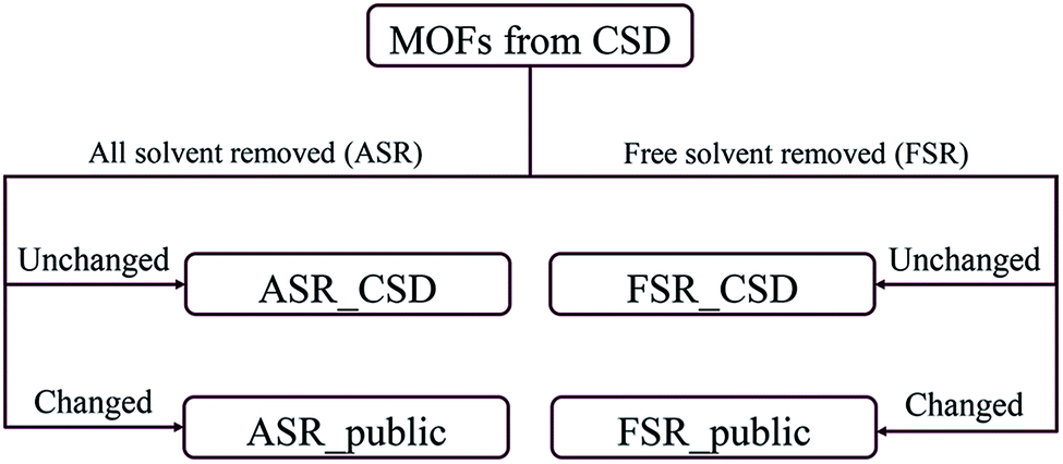 | ||
| Fig. 1 Flow diagram for the construction of CoRE MOF 2019 database. | ||
There are several opportunities to further clean the CoRE MOF 2019 dataset. For example, Chung et al. identified disordered structures as those having atoms closer than 0.1 Å (i.e., overlapping atoms).19 Because the H2 molecule's bond length of 0.74 Å is one of the shortest bond lengths in chemistry, the criterion for overlapping atoms could be made less strict than atoms ≤ 0.1 Å apart. There is also a need to identify missing or misbonded hydrogen atoms and isolated atoms. In this paper, we cleaned the database from the following aspects: (1) isolated atoms (i.e., atoms or atomic ions not directly bonded to any neighboring atoms), (2) atoms too close together (i.e., overlapping atoms), (3) misplaced hydrogen atoms, (4) under-bonded carbon atoms (which might be due to missing hydrogen atoms), and (5) over-bonded carbon atoms. Fig. 2 shows example MOFs for each artifact being screened in this study.
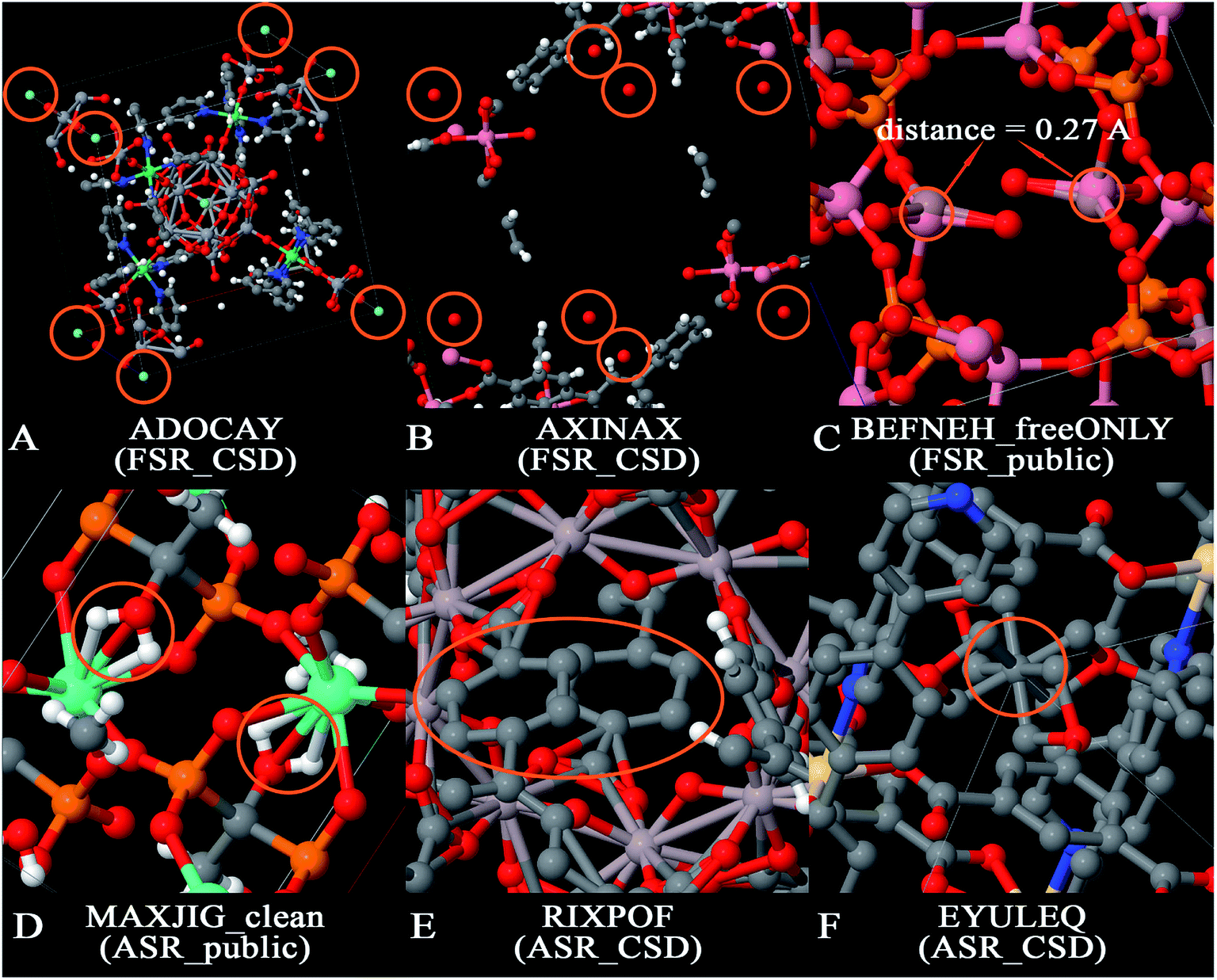 | ||
| Fig. 2 Examples of artifacts being screened in this paper. Panel (A) is an example of isolated atoms in the data that are likewise isolated in the real physical specimen (the circled atoms are F− ions). Panel (B) is an example of isolated atoms in the data that are likely not isolated in the real physical specimen (the circled atoms are oxygen atoms which likely belong to water molecules in the physical specimen for which hydrogen atoms were omitted in the reported crystal structure). Panel (C) is an example of overlapping atoms. Panel (D) is an example of misplaced hydrogens. Panel (E) is an example of under-bonded carbons. Panel (F) is an example of over-bonded carbons. | ||
The term artifacts has the following meaning. First, the term artifact refers to a property of the data rather than a property of the material itself. (Here, the term “material itself” refers to a physical specimen of the material.) For example, X-ray crystallography of a physical specimen containing disordered atoms or twinned crystal structures often yields data (i.e., reported crystal structure geometry) exhibiting overlapping atoms; no overlapping atoms exist in the physical specimen. In this article, the term ‘overlapping atoms’ means atoms that are much too close together. Missing hydrogen atoms is another artifact: the data (i.e., reported crystal structure geometry) is often missing one or more hydrogen atoms, but no hydrogen atoms are missing in the physical specimen of the material. Under-bonded carbon atoms may be caused by missing hydrogen atom(s) in the data; these are normally not under-bonded in the physical specimen. Over-bonded carbon atoms may be caused by overlapping atoms; these are normally not over-bonded in the physical specimen. In this article, the term ‘isolated atom’ does not mean a single atom in empty space, but rather an atom that is not covalently bonded to any neighboring atoms and hence may be labile to easy replacement (e.g., ion exchange). Two different scenarios arise for the isolated atoms. The first scenario corresponds to an isolated atom in both the data and the physical specimen. Fig. 2A shows an example in which a MOF contains isolated F− ions; these ions might be exchangeable for Cl− or other ions if the MOF is placed in solution. Instead of anions, physical specimens might also contain isolated cations (e.g., Na+, Sr+q, etc.) or potentially even an isolated neutral atom. The potential for anion or cation exchange makes it worthwhile to flag these structures. The second scenario corresponds to an isolated atom in the data that is not an isolated atom in the physical specimen. Fig. 2B shows an example in which a reported MOF structure contains isolated O atoms, but these are almost certainly water molecules in the physical specimen for which the hydrogen atoms were not included in the reported crystal structure geometry.
Here, we have flagged rather than deleted structures containing these artifacts. Flagging the structures, rather than deleting them, will make it easier for those structures to be corrected in future work without having to re-insert them into the database. Specifically, any structure corrected in future work could have a new flag added that links to the corrected structure. Also, flagging these artifacts provides flexibility in how the database is used for computational screening studies. Depending on the target application, database users may want to include or exclude various categories of the flagged structures.
As its name indicates, the Computational Ready Experimental (CoRE) MOF database was created for the purpose of providing a library of MOF crystal structures in a format ready to be used as input for large-scale computational screening studies (e.g., classical molecular dynamics or Monte Carlo simulations for gas separation applications).11 Geometries with misbonded atoms (e.g., overlapping atoms, misplaced hydrogen atoms, under-bonded carbons, over-bonded carbons) are not in a format ready to perform classical molecular dynamics or Monte Carlo simulations; hence, the reason for flagging those structures. We also chose to flag structures containing isolated atoms to allow users the ability to choose whether or not to include those structures in their computational screening studies. In some cases, isolated atoms exist in the real physical specimen (e.g., F−, Cl−, Na+, etc.) while in other cases it is an error of the crystal structure refinement procedure (e.g., an isolated O atom in the data that corresponds to a water molecule in the physical specimen for which the H atoms were omitted during crystal structure refinement).
Another opportunity is to perform atom typing and to assign forcefield precursors to the CoRE MOF 2019 structures. After screening for misbonded or isolated atoms, we performed second-neighbor-based atom typing on all accepted structures from the CoRE MOF 2019 dataset. Several forcefield precursors were then assigned to those structures that contained previously parameterized17 atom types. Atom types simplify forcefield parameterization. Sufficiently similar atoms are classified as the same atom type. Atoms of the same type are normally assigned the same forcefield precursor values. Forcefield precursors are building blocks that are combined to construct a force field.20 For example, electrostatic models can be constructed using the net atomic charges21 and/or atomic multipoles and/or polarizabilities and/or electron cloud (charge penetration) parameters. Dispersion models can be constructed using the C6, C8, and/or C10 dispersion coefficients and/or the quantum Drude oscillator parameters. (The C9 dispersion coefficients can also be computed from these forcefield precursors.22) Protocols have to be developed and tested for turning these forcefield precursors into working force fields for MOFs. Simpler forcefield forms, such as Lennard-Jones parameters, can potentially be derived from these forcefield precursors. (Cole et al.23–26 and Nikitin27 introduced methods to compute Lennard-Jones parameters for small molecules and large biomolecules from DDEC atom-in-material descriptors, and they used these in classical atomistic simulations.)
Methods
Our analyses for misbonded atoms used the atom typing radii (ATR) reported in our previous study.17 Our atom typing radii are intended to be effective atomic radii in the typical charge state of the atom in materials. We assigned a bond between two atoms if and only if the distance between them was less than or equal to the sum of their ATR. In our prior work, we optimized these ATR through trial and error (starting from the Open Babel version 1.100.1 connectivity radii as initial guesses) to produce reasonable connectivity results for various MOFs.17 Covalent radii are designed to be effective atomic radii in covalent single bonds.28 In MOFs, metal atoms typically carry positive atomic charges, so the effective atomic radii of metal atoms in MOFs are not necessarily similar to their covalent radii. Specifically, our ATR of metal atoms are often somewhat smaller than their covalent radii. We found this greatly improves connectivity results compared to using covalent radii for atom typing, because using covalent radii for atom typing often yields unreasonably high coordination numbers for metal atoms.The screening was performed on all four subsets: ASR_CSD, ASR_public, FSR_CSD, and FSR_public. An atom was considered isolated if it was not connected to any other atom based on the ATR. Two atoms were considered overlapping if the distance between them was smaller than half the sum of their ATR.
Misplaced hydrogen atoms were identified using the following procedure. For each hydrogen atom, a list was constructed containing atoms located within a distance equal to the sum of ATR plus 0.3 Å. If the list for one hydrogen atom contained at least one metal atom and one oxygen or nitrogen atom, this hydrogen atom was considered misplaced. The rational for this is if a hydrogen atom is bonded to a nitrogen or oxygen, the hydrogen atom will be more positively charged than usual and repelled by positively charged metal atoms. In contrast, hydrogen atoms bonded to carbon are known to be able to participate in agostic bonds (i.e., C–H–metal bonds).29
To screen out structures with under-bonded and/or over-bonded carbon atoms, we performed an empirical carbon bond order analysis. We chose a purely distance-based calculation of bond orders, because misbonded atoms (e.g., overlapping atoms or missing hydrogens) make it unreliable to infer bond orders from connectivity patterns alone. We collected the carbon DDEC6 bond order30 versus bond length information from our previously published 3056 forcefield precursor (FFP) MOFs.17 The data were fit to the following equation
| log10(BO) = A × d + C | (1) |
| BOC–H = min(1.25,−0.6093 × d + 0.5927) | (2) |
| Atom | A (Å−1) | C | R2 |
|---|---|---|---|
| H | −0.6093 | 0.5927 | 0.7584 |
| B | −2.2011 | 3.4380 | 0.9638 |
| C | −1.2685 | 1.8855 | 0.9233 |
| N | −1.2680 | 1.8401 | 0.9255 |
| O | −1.0525 | 1.5189 | 0.9477 |
| Cl | −0.7621 | 1.3723 | 0.9350 |
| Br | −0.8003 | 1.5272 | 0.9776 |
Because carbon has four electrons to share in covalent bonding, the sum of bond orders (SBO) is expected to be approximately four for each carbon atom in most organic and organometallic compounds. The sum of ATR was used to identify all atoms directly bound to each carbon atom. If a carbon atom was bound only to the elements listed in Table 1, and its empirical SBO (computed using the parameters in Table 1) was smaller than 3.3, the structure containing that carbon atom was flagged for under-bonded carbon atom; the structure was flagged for over-bonded carbon atom if the SBO was greater than or equal to 5.5. These empirical SBO thresholds of 3.3 and 5.5 for carbon atoms were set more generous than the DDEC6 SBO thresholds of 3.5 and 4.75 used in our previous study17 to account for the larger chemical uncertainty associated with the empirical SBO value compared to the quantum-mechanically computed DDEC6 SBO value. This wider threshold increases the tolerance for how much a computed carbon SBO could differ from ∼4 before the structure was flagged.
This procedure can screen out structures missing hydrogen atoms on carbon atoms connected only to H, B, C, N, O, Cl, and/or Br atoms. For example, a carbon atom missing a hydrogen atom might have a computed SBO value of ∼3 instead of ∼4. A carbon atom missing two hydrogen atoms might have a computed SBO value of ∼2 instead of ∼4. Notably, this procedure does not screen carbon atoms connected to other elements (e.g., metal atoms) for missing hydrogen atoms. Therefore, more sophisticated screening strategies may be required in future work to identify all structures missing hydrogen atoms. Our goal here was to perform screening that could reliably improve the database by identifying some structures missing hydrogen atoms, even if that screening did not identify all structures missing hydrogen atoms.
A pseudocode for screening out (1) isolated atoms, (2) overlapping atoms, (3) misplaced hydrogens, (4) under-bonded carbons and (5) over-bonded carbons is in ESI Part S17.† A Python function that performs the second-neighbor-based atom typing is in ESI Part S18.† Of course, both the pseudocode of ESI Part S17† and the Python atom typing function of ESI Part S18† look across the periodic boundary conditions to identify all the relevant neighbors of atoms in the reference unit cell, even if some of these neighbors are in adjacent unit cells.
Results and discussion
In the CoRE MOF 2019 database, Chung et al. labeled structures with the distance between two atoms ≤ 0.1 Å as disordered.19 They also manually moved some structures into the disordered category based on user feedback (see DOI: 10.5281/zenodo.3528250). Because disordered atoms make these structures unsuitable for classical atomistic or quantum-mechanical simulations, all of those disordered structures were not included in our present study. The all solvent removal (ASR) criterion is more stringent than the free solvent removal (FSR) criterion.19 This has two implications. First, all structures modified by the FSR procedure should also be modified by the ASR procedure. Therefore, we systematically checked for structures violating this rule and found three: NODTEH, NODTIL and NODTOR. These three were removed from ASR_CSD and added to ASR_public using their FSR_public geometries. Second, all structures unmodified by ASR should also remain unmodified by FSR. Therefore, we added 278 ASR_CSD structures that were not in FSR_CSD to FSR_CSD before the screening. The detailed list is in ESI Part S04.† We removed some structures from the database because their parent structure no longer exists in the CSD database; the list of such structures is in ESI Part S02.†Tables 2 and 3 list the breakdown of flagged structures due to the five major artifacts. Structures not flagged with any of these five artifacts were marked as ‘accepted’. The numbers for each flag criterion do not add up to the total number because of the overlap between categories. The detailed lists of artifacts in structures for each subset are in ESI Part S03.† As summarized in Table 4 and listed in ESI Part S03,† we also searched for structures that did not contain any hydrogen atoms or carbon atoms. Technically, the structures not containing carbon atoms should be referred to as metal–inorganic frameworks (MIFs) rather than as MOFs.15,17,32,33
| Isolated atoms | Misbonded hydrogens | Overlapping atoms | Under-bonded carbons | Over-bonded carbons | Total flagged | Accepted | |
|---|---|---|---|---|---|---|---|
| ASR_CSD | 88 (72) | 20 (16) | 100 (33) | 201 (154) | 137 (70) | 441 | 1204 |
| ASR_public | 819 (718) | 132 (107) | 127 (93) | 1041 (922) | 91 (51) | 2046 | 8100 |
| FSR_CSD | 218 (149) | 44 (28) | 445 (101) | 433 (281) | 481 (127) | 1119 | 1779 |
| FSR_public | 485 (405) | 82 (63) | 70 (46) | 727 (629) | 63 (29) | 1295 | 4713 |
| IA/MH | IA/OA | IA/UC | IA/OC | MH/OA | MH/UC | MH/OC | |
|---|---|---|---|---|---|---|---|
| ASR_CSD | 1 | 5 | 7 | 0 | 0 | 1 | 1 |
| ASR_public | 5 | 12 | 78 | 1 | 3 | 6 | 7 |
| FSR_CSD | 2 | 11 | 30 | 1 | 4 | 3 | 1 |
| FSR_public | 2 | 8 | 62 | 1 | 3 | 5 | 7 |
| OA/UC | OA/OC | UC/OC | IA/MH/OA | IA/MH/UC | IA/MH/OC | IA/OA/UC | |
|---|---|---|---|---|---|---|---|
| ASR_CSD | 12 | 41 | 19 | 0 | 0 | 0 | 2 |
| ASR_public | 7 | 6 | 21 | 1 | 0 | 1 | 1 |
| FSR_CSD | 21 | 243 | 40 | 0 | 0 | 0 | 5 |
| FSR_public | 5 | 3 | 18 | 1 | 1 | 0 | 2 |
| IA/OA/OC | IA/UC/OC | MH/OA/UC | MH/OA/OC | MH/UC/OC | OA/UC/OC | IA/MH/OA/UC | |
|---|---|---|---|---|---|---|---|
| ASR_CSD | 1 | 0 | 1 | 0 | 0 | 5 | 0 |
| ASR_public | 0 | 2 | 2 | 0 | 0 | 2 | 0 |
| FSR_CSD | 16 | 1 | 3 | 3 | 0 | 46 | 0 |
| FSR_public | 0 | 3 | 0 | 0 | 0 | 2 | 0 |
| IA/MH/OA/OC | IA/MH/UC/OC | IA/OA/UC/OC | MH/OA/UC/OC | All 5 | |
|---|---|---|---|---|---|
| ASR_CSD | 0 | 0 | 0 | 0 | 0 |
| ASR_public | 0 | 0 | 0 | 0 | 0 |
| FSR_CSD | 0 | 0 | 3 | 0 | 0 |
| FSR_public | 0 | 0 | 0 | 0 | 0 |
| Total structures | No hydrogens | No carbons | |
|---|---|---|---|
| ASR_CSD | 1645 | 48 | 9 |
| ASR_public | 10![[thin space (1/6-em)]](https://www.rsc.org/images/entities/char_2009.gif) 146 146 |
859 | 463 |
| FSR_CSD | 2898 | 74 | 10 |
| FSR_public | 6008 | 473 | 300 |
In our previous study, we reported 7033 second-neighbor-based atom types for the FFP MOFs with their forcefield precursor parameters.17 The standard deviation of calculated forcefield precursor values was relatively small across atoms sharing the same second neighbor environments.17 ESI Parts S05–S08† list second-neighbor-based atom types contained in each structure for the accepted_ASR_CSD, accepted_ASR_public, accepted_FSR_CSD, and accepted_FSR_public sets. ESI Part S09† lists the frequencies for all atom types in these subsets. 3274 different atom types were found in the accepted_ASR_CSD structures, 14710 in accepted_ASR_public structures, 4911 in accepted_FSR_CSD structures, and 11175 in accepted_FSR_public structures. This clearly demonstrates high chemical diversity in the 2019 CoRE MOF database. ESI Parts S10 and S11† list the XYZ coordinates and atom type for each atom in the accepted_ASR_public and accepted_FSR_public structures. XYZ coordinates for the CSD structures must be obtained through the CSD.12,13
In general, two crystal structures could be considered to be chemically equivalent if all of the following criteria are met:
(1) The two structures contain the same chemical elements.
(2) The number of atoms of each chemical element divided by the unit cell volume is the same for both structures. This criterion identifies a non-interpenetrating MOF and an interpenetrating version of this MOF as distinct structures; in this case, the interpenetrating MOF would have twice the number of atoms of each chemical element per unit cell volume compared to the non-interpenetrating MOF.15
(3) The two structures have similar geometric conformations. Rotational and translational invariance must be considered when evaluating this criterion. This criterion distinguishes two MOFs having similar chemical elements arranged in different chemical conformations. For example, two different geometric isomers, enantiomers (optical isomers), or other conformations would be considered different structures.
(4) The two structures have the same crystal polymorph.
Here, we are interested in the more restricted question of whether two structures having the same reference code but appearing in two different datasets are equivalent. Two structures having the same reference code were derived from the same experimental crystal structure (i.e., same physical specimen) using different cleaning protocols. Because these structures were derived from the same experimental crystal structure, criteria (3) and (4) are necessarily satisfied if criteria (1) and (2) are satisfied. Therefore, an ASR_public structure with reference code (e.g., XXXXXX_clean) was considered equivalent to a corresponding FSR_public structure having analogous reference code (e.g., XXXXXX_freeONLY) if and only if criteria (1) and (2) above are satisfied. Two reference codes were considered to be analogous if they had the same journal-based code or six-digit CSD code, irrespective of the added CoRE MOF suffix (e.g., _clean, _freeONLY). Therefore, two structures of different subsets having the same reference code were considered equivalent if they satisfied criteria (1) and (2) above. We did not screen for whether two structures having different reference codes (i.e., derived from two different physical specimens) were equivalent. We found 3924 structures shared between the ASR_public and FSR_public subsets, 2606 structures shared between the ASR_public and FFP17 sets, and 1054 structures shared between FSR_public subset and FFP sets. These shared structures represent cases for which two different cleaning procedures (i.e., ASR, FSR, CoRE2014) produced identical ‘cleaned’ structures derived from the same physical specimen. We report the codes for these shared structures in ESI Part S12.†
In contrast, ESI Part S13† lists composition differences between ASR_public and FSR_public structures that have the same reference codes but different chemical compositions. These structures do not satisfy criterion (1) and/or (2) above. These are cases for which the FSR cleaning procedure produced a substantially different result than the ASR cleaning procedure applied to the experimental crystal structure of the same physical specimen.
ESI Part S14† lists the 700 accepted_ASR_CSD, 4701 accepted_ASR_public, 716 accepted_FSR_CSD, and 1904 accepted_FSR_public structures that can be fully described by the 7033 atom types for which we previously reported17 forcefield precursor values. These structures are computational ready for forcefield simulations using our reported atom type forcefield precursor parameters. ESI Parts S15 and S16† list the XYZ coordinates together with the following forcefield precursor values for every atom in accepted_ASR_public and accepted_FSR_public structures that can be fully described by the reported atom types: net atomic charge;34,35 C6, C8, and C10 dispersion coefficients;22,36 three kinds of polarizabilities (i.e., fluctuating, isotropic forcefield, and static);22,36 parameters fitting the atom's electron density tail to an exponential function (i.e., electron cloud parameters);17 〈r3〉 and 〈r4〉 radial moments; quantum Drude oscillator parameters;22,36 and atomic dipole magnitude. The atomic spin moment is not included here among the forcefield precursors, because magnetic ordering is almost energy degenerate (and hence hard to accurately predict) in some materials.37,38
The net atomic charges in these structures were rescaled to make the overall unit cell charge equal zero. If the unit cell charge before rescaling was >0, then only the NACs > 0 were proportionally rescaled to make the rescaled unit cell charge zero. If the unit cell charge before rescaling was <0, then only the NACs < 0 were proportionally rescaled to make the rescaled unit cell charge zero. This conservative rescaling changes the NAC magnitudes by the smallest percentage possible to achieve unit cell neutrality while never increasing the NAC magnitude for any atom. Because the root-mean-squared error (RMSE) of the electrostatic potential is more sensitive to large magnitude NACs than to small magnitude NACs, we chose not to increase NAC magnitudes during rescaling.
These forcefield precursors reported for 5000+ MOFs could be used in future work to construct working interaction models for MOFs. The simplest useful force field would consist of Lennard-Jones parameters plus the atomic charges to describe short-range repulsive interactions, long-range dispersion interactions, and electrostatic interactions between atoms in the material. A flexible force field would also require bonded atom parameters such as bond springs, angle springs, and torsion parameters. The Manz research group is currently in the process of developing and testing short-range repulsion formulas that are computed from the electron cloud parameters reported herein as force field precursors. We are also using this short-range repulsion function as the basis to construct the argument for Tang–Toennies damping39,40 of the C6, C8, and C10 dispersion terms reported herein. Finally, the Manz research group is currently testing this short-range repulsion together with damped dispersion and intends to publish a follow-up article that will describe how to turn these forcefield precursors into working interaction models.
Conclusion
In this paper, we screened the 2019 CoRE MOF database to flag structures containing isolated or misbonded atoms: (i) atoms not directly bonded to any neighboring atoms (i.e., ‘isolated’ atoms), (ii) atoms too close together (i.e., overlapping atoms), (iii) misplaced hydrogen atoms, (iv) under-bonded carbon atoms (which might be caused by missing hydrogen atoms), and (v) over-bonded carbon atoms. Depending on the situation, an ‘isolated’ atom may correspond to an exchangeable atom (e.g., F−, Cl−, Na+, Sr+q) or an error of the crystal structure refinement procedure (e.g., a water molecule whose hydrogen atoms were not reported could appear as an isolated oxygen atom). This study should not be viewed as the final cleaning of this database, but rather as progress along the way towards the goal of someday achieving a completely cleaned set of experimentally-derived MOF crystal structures. This resulted in the following numbers of accepted structures: 1204 in accepted_ASR_CSD, 8100 in accepted_ASR_public, 1779 in accepted_FSR_CSD, and 4713 in accepted_FSR_public. We performed several kinds of comparative analysis: (a) structures not containing hydrogen or carbon atoms, (b) structures common to two or more of the datasets, and (c) composition differences between ASR_public and FSR_public structures having the same reference codes. We performed atom typing for all of the accepted structures. We identified 700 of 1204 accepted_ASR_CSD, 4701 of 8100 accepted_ASR_public, 716 of 1779 accepted_FSR_CSD, and 1904 of 4713 accepted_FSR_public structures that can be parameterized by our previously reported17 forcefield precursors. For accepted_ASR_public and accepted_FSR_public structures that can be described by the reported atom types, the following forcefield precursors are listed for each atom: net atomic charge; C6, C8, and C10 dispersion coefficients; three kinds of polarizabilities (i.e., fluctuating, isotropic forcefield, and static); parameters fitting the atom's electron density tail to an exponential function (i.e., electron cloud parameters); 〈r3〉 and 〈r4〉 radial moments; quantum Drude oscillator parameters; and atomic dipole magnitude. The procedures and results are summarized in Fig. 3. In summary, our results facilitate future computational screening studies of MOFs by making this database cleaner and by providing atom types and forcefield precursors. Future work will address the task of turning these forcefield precursors into working force fields.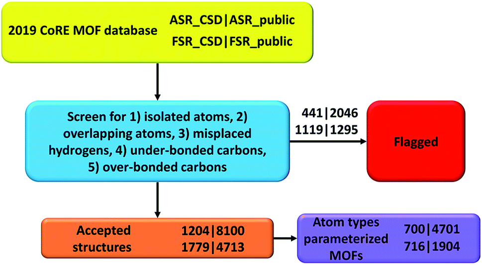 | ||
| Fig. 3 Flow diagram of this project. | ||
Authors' contributions
T. C. performed the computational screening and data analysis. Both authors designed the study and wrote the manuscript.Conflicts of interest
There are no conflicts of interest to declare.Acknowledgements
NSF CAREER award DMR-1555376 provided financial support. The Extreme Science and Engineering Discovery Environment (NSF ACI-1548562) project TG-CTS100027 provided computational time on the Comet cluster at the San Diego Supercomputing Center.References
- H. Furukawa, K. E. Cordova, M. O'Keeffe and O. M. Yaghi, The chemistry and applications of metal-organic frameworks, Science, 2013, 341, 1230444 CrossRef PubMed.
- S. L. James, Metal-organic frameworks, Chem. Soc. Rev., 2003, 32, 276–288 RSC.
- Y. J. Cui, Y. F. Yue, G. D. Qian and B. L. Chen, Luminescent functional metal-organic frameworks, Chem. Rev., 2012, 112, 1126–1162 CrossRef CAS PubMed.
- A. Schneemann, V. Bon, I. Schwedler, I. Senkovska, S. Kaskel and R. A. Fischer, Flexible metal-organic frameworks, Chem. Soc. Rev., 2014, 43, 6062–6096 RSC.
- A. Corma, H. Garcia and F. X. Llabrés i Xamena, Engineering metal organic frameworks for heterogeneous catalysis, Chem. Rev., 2010, 110, 4606–4655 CrossRef CAS PubMed.
- Y. B. He, F. L. Chen, B. Li, G. D. Qian, W. Zhou and B. L. Chen, Porous metal-organic frameworks for fuel storage, Coord. Chem. Rev., 2018, 373, 167–198 CrossRef CAS.
- J. Lee, O. K. Farha, J. Roberts, K. A. Scheidt, S. T. Nguyen and J. T. Hupp, Metal-organic framework materials as catalysts, Chem. Soc. Rev., 2009, 38, 1450–1459 RSC.
- K. Sumida, D. L. Rogow, J. A. Mason, T. M. McDonald, E. D. Bloch, Z. R. Herm, T. H. Bae and J. R. Long, Carbon dioxide capture in metal-organic frameworks, Chem. Rev., 2012, 112, 724–781 CrossRef CAS PubMed.
- J. R. Li, J. Sculley and H. C. Zhou, Metal-organic frameworks for separations, Chem. Rev., 2012, 112, 869–932 CrossRef CAS PubMed.
- A. U. Czaja, N. Trukhan and U. Muller, Industrial applications of metal-organic frameworks, Chem. Soc. Rev., 2009, 38, 1284–1293 RSC.
- Y. G. Chung, J. Camp, M. Haranczyk, B. J. Sikora, W. Bury, V. Krungleviciute, T. Yildirim, O. K. Farha, D. S. Sholl and R. Q. Snurr, Computation-ready, experimental metal-organic frameworks: a tool to enable high-throughput screening of nanoporous crystals, Chem. Mater., 2014, 26, 6185–6192 CrossRef CAS.
- C. R. Groom, I. J. Bruno, M. P. Lightfoot and S. C. Ward, The Cambridge Structural Database, Acta Crystallogr., Sect. B: Struct. Sci., Cryst. Eng. Mater., 2016, 72, 171–179 CrossRef CAS PubMed.
- F. H. Allen, The Cambridge Structural Database: a quarter of a million crystal structures and rising, Acta Crystallogr., Sect. B: Struct. Sci., 2002, 58, 380–388 CrossRef PubMed.
- A. Sturluson, M. T. Huynh, A. R. Kaija, C. Laird, Y. Sunghyun, F. Hou, Z. Feng, C. E. Wilmer, Y. J. Colon, Y. G. Chung, D. W. Siderius and C. M. Simon, The role of molecular modelling and simulation in the discovery and deployment of metal-organic frameworks for gas storage and separation, Mol. Simul., 2019, 45, 1082–1121 CrossRef CAS PubMed.
- S. Barthel, E. V. Alexandrov, D. M. Proserpio and B. Smit, Distinguishing metal-organic frameworks, Cryst. Growth Des., 2018, 18, 1738–1747 CrossRef CAS PubMed.
- C. Altintas, G. Avci, H. Daglar, A. N. V. Azar, I. Erucar, S. Velioglu and S. Keskin, An extensive comparative analysis of two MOF databases: high-throughput screening of computation-ready MOFs for CH4 and H2 adsorption, J. Mater. Chem. A, 2019, 7, 9593–9608 RSC.
- T. Chen and T. A. Manz, A collection of forcefield precursors for metal-organic frameworks, RSC Adv., 2019, 9, 36492–36507 RSC.
- S. Velioglu and S. Keskin, Revealing the effect of structure curations on the simulated CO2 separation performances of MOFs, Mater. Adv., 2020, 1, 341–353 RSC.
- Y. G. Chung, E. Haldoupis, B. J. Bucior, M. Haranczyk, S. Lee, H. D. Zhang, K. D. Vogiatzis, M. Milisavljevic, S. Ling, J. Camp, B. Slater, J. Siepmann, D. Sholl and R. Snurr, Advances, updates, and analytics for the computation-ready, experimental metal-organic framework database: CoRE MOF 2019, J. Chem. Eng. Data, 2019, 64, 5985–5998 CrossRef CAS.
- Q. Y. Yang, D. H. Liu, C. L. Zhong and J. R. Li, Development of computational methodologies for metal-organic frameworks and their application in gas separations, Chem. Rev., 2013, 113, 8261–8323 CrossRef CAS PubMed.
- T. Watanabe, T. A. Manz and D. S. Sholl, Accurate treatment of electrostatics during molecular adsorption in nanoporous crystals without assigning point charges to framework atoms, J. Phys. Chem. C, 2011, 115, 4824–4836 CrossRef CAS.
- T. A. Manz, T. Chen, D. J. Cole, N. Gabaldon Limas and B. Fiszbein, New scaling relations to compute atom-in-material polarizabilities and dispersion coefficients: part 1. Theory and accuracy, RSC Adv., 2019, 9, 19297–19324 RSC.
- D. J. Cole, J. Z. Vilseck, J. Tirado-Rives, M. C. Payne and W. L. Jorgensen, Biomolecular force field parameterization via atoms-in-molecule electron density partitioning, J. Chem. Theory Comput., 2016, 12, 2312–2323 CrossRef CAS PubMed.
- J. T. Horton, A. E. A. Allen and D. J. Cole, Modelling flexible protein-ligand binding in p38α MAP kinase using the QUBE force field, Chem. Commun., 2020, 56, 932–935 RSC.
- J. T. Horton, A. E. A. Allen, L. S. Dodda and D. J. Cole, QUBEKit: automating the derivation of force field parameters from quantum mechanics, J. Chem. Inf. Model., 2019, 59, 1366–1381 CrossRef CAS PubMed.
- A. E. A. Allen, M. J. Robertson, M. C. Payne and D. J. Cole, Development and validation of the quantum mechanical bespoke protein force field, ACS Omega, 2019, 4, 14537–14550 CrossRef CAS PubMed.
- A. Nikitin, Non-zero Lennard-Jones parameters for the Toukan–Rahman water model: more accurate calculations of the solvation free energy of organic substances, J. Comput.-Aided Mol. Des., 2020, 34, 437–441 CrossRef CAS PubMed.
- B. Cordero, V. Gomez, A. E. Platero-Prats, M. Reves, J. Echeverria, E. Cremades, F. Barragan and S. Alvarez, Covalent radii revisited, Dalton Trans., 2008, 2832–2838 RSC.
- M. Brookhart, M. L. H. Green and G. Parkin, Agostic interactions in transition metal compounds, Proc. Natl. Acad. Sci. U. S. A., 2007, 104, 6908–6914 CrossRef CAS PubMed.
- T. A. Manz, Introducing DDEC6 atomic population analysis: part 3. Comprehensive method to compute bond orders, RSC Adv., 2017, 7, 45552–45581 RSC.
- L. Pauling, Atomic radii and interatomic distances in metals, J. Am. Chem. Soc., 1947, 69, 542–553 CrossRef CAS.
- N. Ding, G. S. Armatas and M. G. Kanatzidis, Metal inorganic frameworks: dynamic flexible architecture with extended pore order built from [Se3]2− linkers and [Re6Se6Br8]2− clusters, J. Am. Chem. Soc., 2010, 132, 6728–6734 CrossRef CAS PubMed.
- S. Kumar, M. Samolia and T. J. D. Kumar, Hydrogen storage in Sc and Li decorated metal–inorganic framework, ACS Appl. Energy Mater., 2018, 1, 1328–1336 CrossRef CAS.
- T. A. Manz and N. Gabaldon Limas, Introducing DDEC6 atomic population analysis: part 1. Charge partitioning theory and methodology, RSC Adv., 2016, 6, 47771–47801 RSC.
- N. Gabaldon Limas and T. A. Manz, Introducing DDEC6 atomic population analysis: part 2. Computed results for a wide range of periodic and nonperiodic materials, RSC Adv., 2016, 6, 45727–45747 RSC.
- T. A. Manz and T. Chen, New scaling relations to compute atom-in-material polarizabilities and dispersion coefficients: part 2. Linear-scaling computational algorithms and parallelization, RSC Adv., 2019, 9, 33310–33336 RSC.
- N. Gabaldon Limas and T. A. Manz, Introducing DDEC6 atomic population analysis: part 4. Efficient parallel computation of net atomic charges, atomic spin moments, bond orders, and more, RSC Adv., 2018, 8, 2678–2707 RSC.
- T. A. Manz and D. S. Sholl, Methods for computing accurate atomic spin moments for collinear and noncollinear magnetism in periodic and nonperiodic materials, J. Chem. Theory Comput., 2011, 7, 4146–4164 CrossRef CAS PubMed.
- K. T. Tang and J. P. Toennies, An improved simple-model for the van der Waals potential based on universal damping functions for the dispersion coefficients, J. Chem. Phys., 1984, 80, 3726–3741 CrossRef CAS.
- K. T. Tang and J. P. Toennies, The damping function of the van der Waals attraction in the potential between rare-gas atoms and metal surfaces, Surf. Sci., 1992, 279, L203–L206 CrossRef CAS.
Footnote |
| † Electronic supplementary information (ESI) available: Two compressed 7-zip archives containing: S01 raw data for the fitting of eqn (1); S02 list of nonexistent CSD codes; S03 breakdown of artifacts in each subset; S04 CSD codes of ASR_CSD structures added to FSR_CSD subset; S05–S08 lists of atom types contained in each accepted structure for each subset; S09 lists of individual atom type frequencies for each subset; S10 and S11 atom types with XYZ coordinates for accepted_ASR_public and accepted_FSR_public subsets; S12 lists of structures shared between ASR_public & FSR_public, ASR_public & FFP structures, and FSR_public & FFP structures; S13 list of composition differences between ASR_public and FSR_public structures that have the same reference codes; S14 lists of structures for each subset that can be described by parameterized atom types from our previous study; S15 and S16 forcefield precursors for accepted_ASR_public and accepted_FSR_public structures that can be described by the reported atom types; S17 pseudocode for screening MOFs for the following artifacts: isolated atoms, overlapping atoms, misplaced hydrogens, under-bonded carbons, and over-bonded carbons; S18 Python function for assigning second-neighbor-based atom types. See DOI: 10.1039/d0ra02498h |
| This journal is © The Royal Society of Chemistry 2020 |