 Open Access Article
Creative Commons Attribution 3.0 Unported Licence
Rapid, portable and cost-effective yeast cell viability and concentration analysis using lensfree on-chip microscopy and machine learning†
Alborz
Feizi
abc,
Yibo
Zhang
a,
Alon
Greenbaum
ad,
Alex
Guziak
e,
Michelle
Luong
f,
Raymond Yan Lok
Chan
a,
Brandon
Berg
eg,
Haydar
Ozkan
a,
Wei
Luo
a,
Michael
Wu
a,
Yichen
Wu
a and
Aydogan
Ozcan
*abch
aDepartment of Electrical Engineering, University of California Los Angeles (UCLA), USA. E-mail: ozcan@ucla.edu; Web: http://www.innovate.ee.ucla.edu Web: http://org.ee.ucla.edu
bDepartment of Bioengineering, University of California Los Angeles (UCLA), USA
cCalifornia Nanosystems Institute (CNSI), University of California Los Angeles (UCLA), USA
dDivision of Biology and Biological Engineering, California Institute of Technology, USA
ePhysics and Astronomy Department, University of California Los Angeles (UCLA), USA
fDepartment of Microbiology, Immunology, and Molecular Genetics, University of California (UCLA), USA
gPhysics Department, University of Michigan, USA
hDepartment of Surgery, David Geffen School of Medicine, University of California (UCLA), USA
First published on 23rd September 2016
Abstract
Monitoring yeast cell viability and concentration is important in brewing, baking and biofuel production. However, existing methods of measuring viability and concentration are relatively bulky, tedious and expensive. Here we demonstrate a compact and cost-effective automatic yeast analysis platform (AYAP), which can rapidly measure cell concentration and viability. AYAP is based on digital in-line holography and on-chip microscopy and rapidly images a large field-of-view of 22.5 mm2. This lens-free microscope weighs 70 g and utilizes a partially-coherent illumination source and an opto-electronic image sensor chip. A touch-screen user interface based on a tablet-PC is developed to reconstruct the holographic shadows captured by the image sensor chip and use a support vector machine (SVM) model to automatically classify live and dead cells in a yeast sample stained with methylene blue. In order to quantify its accuracy, we varied the viability and concentration of the cells and compared AYAP's performance with a fluorescence exclusion staining based gold-standard using regression analysis. The results agree very well with this gold-standard method and no significant difference was observed between the two methods within a concentration range of 1.4 × 10⁵ to 1.4 × 10⁶ cells per mL, providing a dynamic range suitable for various applications. This lensfree computational imaging technology that is coupled with machine learning algorithms would be useful for cost-effective and rapid quantification of cell viability and density even in field and resource-poor settings.
Introduction
Yeast cells are frequently used in alcoholic beverage and baking industry to make e.g., beer, wine, and bread.1–3 Furthermore, with the rapid depletion of fossil fuel reserves, biofuel production using yeast is emerging.4–7 Monitoring the concentration and viability of these cells allows for fine-tuning of fermentation parameters, which is crucial for both research laboratories and the industry.8–10 Therefore, biofuel, alcoholic beverage and baking industries can benefit from a rapid and cost-effective yeast viability and concentration analysis method.On the other hand, current methods of yeast viability testing are time-consuming and require expensive equipment. The most common method is to use a haemocytometer cassette together with a bench-top microscope and manually identify cells in a stained sample. This method is tedious and time-consuming11 and the use of a lateral mechanical scanning stage is highly recommended to achieve high accuracy with this method,8 further exemplifying its expensive and laborious nature. Alternatively, flow-cytometers can be used to quickly assess the viability of yeast cells.12 However, this method also demands relatively expensive and bulky equipment, and typically requires a technician to operate. More recently, imaging cytometry systems have made the counting process automatic by combining fluorescence and bright-field imaging modalities and applying automatic counting algorithms.13 However, such systems are also relatively costly and bulky due to the need for lenses and motorized hardware assemblies. Home-brewers, small breweries, restaurants and citizens producing ethanol fuel at home,14–17 typically do not have access to such equipment.
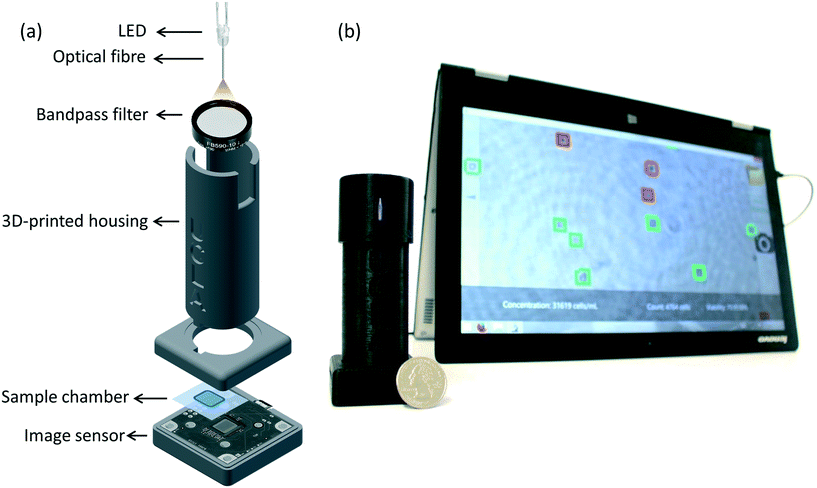
Here, we present a portable and cost-effective automatic yeast analysis platform (AYAP) that rapidly measures the concentration and viability of stained yeast cells. As seen in Fig. 1, AYAP features a lens-free on-chip microscope18–21 that weighs approximately 70 g and has dimensions of 4 × 4 × 12 cm. This lens-free setup uses a light-emitting diode (LED) coupled to a multimode optical fibre (core size: 0.1 mm) and a band-pass optical filter, outputting partially-coherent light that illuminates the sample. A complementary metal oxide semiconductor (CMOS) image sensor chip captures the holographic shadows of the sample, which are sent to a user-friendly touch-screen interface for automated analysis, running on a tablet-PC. This graphical user interface reconstructs an image of the object plane using these holographic shadows and utilizes a pre-trained machine-learning model to rapidly identify live and dead cells in a stained sample. For the stain, we used methylene blue, which is stable at room temperature, making it ideal for our portable platform. AYAP rapidly captures and analyses a large imaging field-of-view (FOV) of ∼22.5 mm2, allowing for the analysis of an order of magnitude larger sample area compared to a conventional 10× microscope objective-lens.
This manuscript reports, for the first time, automated measurement of cell viability using a machine learning algorithm implemented on lens-free reconstructed images of colour-stained cells and demonstrates the success of this computational approach in measuring the viability and concentration of Saccharomyces cerevisiae – the most common yeast species used in the food, alcoholic beverage, and biofuel industries.10,22,23 There exist many strains within this species with very similar morphology and size.22,24,25 Among these, we selected the distillers active dry yeast of the Saccharomyces cerevisiae due to its wide-scale use in various applications and industries. By varying the viability and concentration of these yeast cells in our experiments, we compared AYAP's performance with fluorescence exclusion staining using regression analysis. No significant difference was found between the two methods within a large concentration range of 0.14 million to 1.4 million cells per millilitre, validating the accuracy of yeast viability and concentration analysis performed using our computational platform. This light-weight, compact and cost-effective platform will be useful for rapid and accurate quantification of cell viability and concentration.
Materials and methods
Sample preparation
Distillers active dry yeast (DADY) was rehydrated in distilled water. 1![[thin space (1/6-em)]](https://www.rsc.org/images/entities/char_2009.gif) :
:![[thin space (1/6-em)]](https://www.rsc.org/images/entities/char_2009.gif) 1 volume of 0.1% w/v methylene blue was added to the yeast solution to stain the dead cells.
1 volume of 0.1% w/v methylene blue was added to the yeast solution to stain the dead cells.
The microfluidic counting chamber consists of two coverslips and an adhesive tape (CS Hyde, 45-3A-1) used as a spacer. In order to build the microfluidic chamber, adhesive tape was cut in the shape of a square and was attached to a coverslip (0.13–0.17 mm thickness). Before adding the yeast solution to the chamber, a second coverslip was placed on top of the adhesive tape, with a small opening at the edge. The sample was slowly injected into the microfluidic chamber through the small opening. The yeast solution disburses through the chamber via capillary action, allowing uniform distribution of the yeast cells within our imaging FOV. Lastly, we slid the top cover slip to close the small opening and to prevent evaporation.
Design of the field-portable lens-free microscope
The sample was directly placed on top of a CMOS image sensor chip (ON Semiconductor, MT9J003STM) with a pixel size of 1.67 μm. An LED with a peak wavelength of 590 nm (Kingbright, WP7113SYC/J3) was used as the illumination source. A hole was drilled into the lens of the LED using a 300 μm-diameter drill bit. A multimode fibre (100 μm core diameter, Thorlabs, AFS-105/125Y) was inserted into the drilled hole and fixed using optical glue. The beam exiting the optical fibre passes through a band-pass filter (4 nm bandwidth, centred around 590 nm, Thorlabs, FB590-10) to improve the temporal coherence of the illumination light at the sensor plane. The distance between the cleaved end of the optical fibre and the image sensor is approximately 6 cm. A 3 V coin battery powers the LED. All the components fit within a 3D printed housing (3D printer: Stratasys, Dimensions Elite) made using acrylonitrile butadiene styrene (ABS) material (see Fig. 1a).Hologram reconstruction
The captured holograms of the sample are back-propagated to the object plane using the angular spectrum method.26–30 The hologram is first transformed to the spatial frequency domain using a fast Fourier transform (FFT). Then a phase factor, which is a function of the wavelength, propagation distance, and refractive index of the medium, is multiplied with the angular spectrum.27 Finally it is inverse-Fourier-transformed to the spatial domain to obtain the back-propagated image of the specimen.27 For cell viability analysis, we did not perform any additional phase retrieval or twin image elimination routines, although these could also be used for refinement of the reconstructed images, if needed.Automated counting and labelling of imaged cells using machine-learning
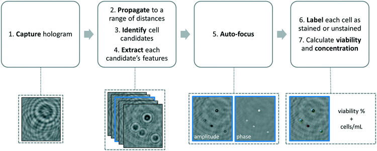
We developed a machine-learning algorithm to classify stained and unstained cells from a reconstructed digital hologram and quantify cell viability and concentration (see Fig. 2). This algorithm uses an SVM model31,32 based on 10 spatial features extracted from each cell candidate: area, perimeter, maximum pixel value on the phase image, maximum pixel value on the amplitude image, minimum pixel value on the phase image, minimum pixel value on the amplitude image, mean pixel value on the phase image, mean pixel value on the amplitude image, standard deviation of the pixel values on the phase image, and the standard deviation of the pixel values on the amplitude image. The training data was populated from two experiments, where 260 stained and 260 unstained cells were manually identified on the reconstructed digital hologram and individually confirmed using a high-resolution bench-top microscope (Olympus BX51, 10× objective lens with 0.3 NA, and Retiga 2000R CCD camera) as ground truth. In order to validate the predictive capabilities of this library, 5-fold cross-validation was performed.33 We found that the percentage of unstained cells correctly identified was 96.5%, the percentage of stained cells correctly identified was 96.9%, the percentage of unstained cells falsely identified as stained was 3.5%, and finally the percentage of stained cells falsely identified as unstained was 3.1%.The image processing and cell classification algorithm digitally divides the full-FOV hologram into six tiles (each with a FOV of ∼3.8 mm2) and processes each sub-FOV individually, which helps to minimize the effects of (1) the possible tilting or misalignment of the sample chamber with respect to the sensor chip plane, and (2) variances in the thickness of the sample holders. Our algorithm performs digital auto-focusing at each sub-FOV using the trained machine-learning library. In order to do so, we reconstruct the acquired digital holograms at multiple distances (z2) from the image sensor chip. Next, the cell candidates are identified at each z2 using thresholding and mathematical morphology operations and fed into the trained SVM model for classification. An SVM classification score si (i = 1, …, N) which refers to the signed distance from our decision boundary is calculated for each cell candidate in a given tile, where N is the total number of cell candidates. The distance with the largest mean absolute classification score is chosen as the optimal z2 distance for that specific sub-FOV, i.e.:
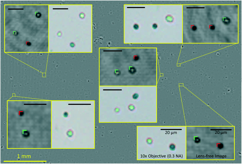
This focus criterion described above is also used for labelling and cell viability calculations using the same trained classifier. Next, among all the cell candidates within a given sub-FOV, the majority of clumps, dust particles, and twin-image related artifacts are removed based on an SVM classification score threshold. Most of these micro-objects lie close to our decision boundary and have the lowest absolute classification scores. An SVM score threshold was determined in order to exclude some of these false classifications from our viability calculations. The number of cell candidates eliminated based on this SVM classification score threshold is approximately 15% of the total number of cell candidates in a given FOV. The remaining cells that are classified into stained and unstained cell categories based on their SVM classification scores are accordingly labelled using colour markings on the reconstructed image (see Fig. 3 and 4) and the viability percentage of the entire FOV is calculated by dividing the number of unstained cells by the total number of cells. Finally, the concentration is calculated by dividing the number of identified cells by the sample volume (∼4.5 μL) that is analysed by our imaging system.
Touch-screen graphical user interface (GUI)
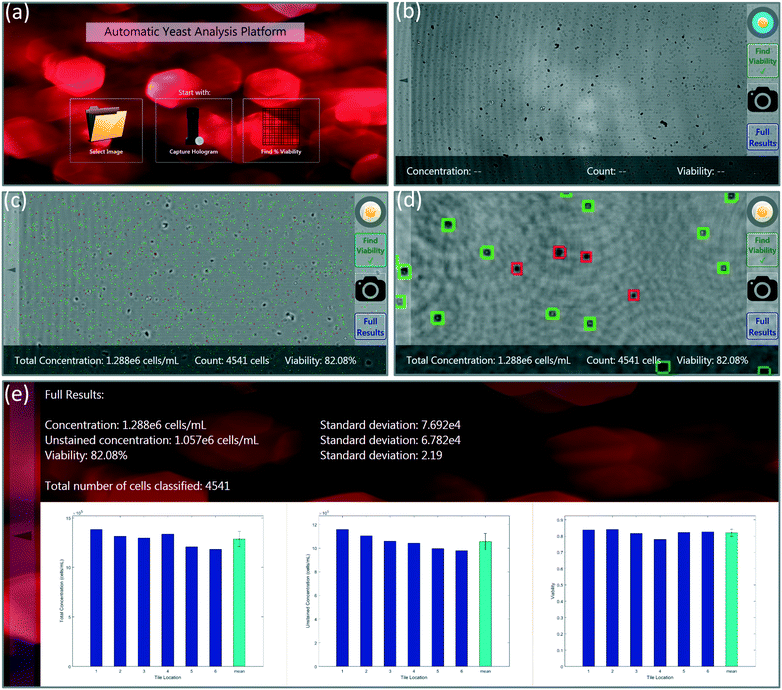
A custom-designed touch-screen interface based on a tablet-PC (Lenovo Yoga 2, Intel Core i7, 8GB RAM) was created to work with our field-portable lens-free microscope. This interface allows the user to load a previously captured sample hologram or directly capture a new hologram using the field-portable microscope, automatically setting the image capture settings (Fig. 3a and b). Next, the user has the ability to run our machine-learning algorithm on the holographic image that is captured. The tablet interface either uses the auto-focusing algorithm described earlier, in which case the entire analysis can take 5–10 minutes to run for each test, depending on the number of cells within the sample volume. Alternatively, we can also use a list of previously calculated optimal propagation distances (z2 per-tile), in which case the entire processing takes less than 30 seconds to run on our tablet-PC. In our experiments, we noticed that the optimal propagation distances are consistent from test-to-test when using the same batch of coverslips in our microfluidic sample chambers; therefore, we ran the auto-focus algorithm only once, and applied the same optimal distances to later experiments using the same batch of sample holders (see Fig. 5). SVM-classified stained and unstained cells, labelled using the red and green markers respectively, are then displayed to the user. The user has the capability to digitally zoom within a given image and inspect each labelled cell. Through the same GUI, the user can observe the unstained cell concentration, total cell concentration, and the viability of each of the six tiles/sub-FOVs in three separate bar graphs. Additionally, the average concentration and viability information along with the standard deviations within the tiles are all displayed to the user (Fig. 3d and e).Results and discussion
There is a large number of methods that can be used for quantifying the viability of cells. One of the established methods of determining cell viability is exclusion staining. In this method, dead cells are stained, and after counting the number of stained and unstained cells, a number between 0% and 100% is used to indicate the cell viability of the sample.34–36 There are multiple exclusion stains used in industry to perform yeast viability testing.37–39 One commonly used stain is methylene blue,40,41 which is inexpensive, can be stored at room temperature, and has a relatively low toxicity to humans.42 However, conventional methylene blue exclusion testing methods suffer from (1) false positive results at longer exposure times,39 and (2) operator subjectivity, which is an important disadvantage compared to fluorescence-based staining methods (e.g., using propidium iodide).43,44Our computational platform does not suffer from these reported disadvantages of methylene blue because (1) it captures an image of the sample over a large field of view and volume (∼4.5 μL) in less than 10 seconds, therefore, reducing false positives, and (2) our machine-learning algorithm eliminates operator subjectivity. For these reasons, methylene blue provides a very good staining method for our computational platform due to its more practical and cost-effective nature.
The automated yeast viability and concentration results obtained using methylene blue in our lensfree computational imaging system were compared with manual measurements of viability and concentration based on fluorescence staining of dead cells using propidium iodide. These two methods were compared at various levels of cell viability and concentrations. We divided each sample under test into two sub-samples of equal volume, staining one with our choice, methylene blue, and the other with propidium iodide. For each test, four to five 10× objective lens (NA = 0.3) images of the propidium iodide stained samples were captured and manually labelled using benchtop fluorescence microscopy. A single lensfree image of the methylene blue sample was captured via AYAP. AYAP divides the large FOV into six tiles and processes each tile independently. In our experiments we found out that when using the same batch of cover slips for our microfluidic chambers, the optimal propagation distances are consistent from chamber to chamber, eliminating the need for repeated digital auto-focusing, which makes the total analysis time for each sample less than 30 seconds, even using a modest tablet-PC.
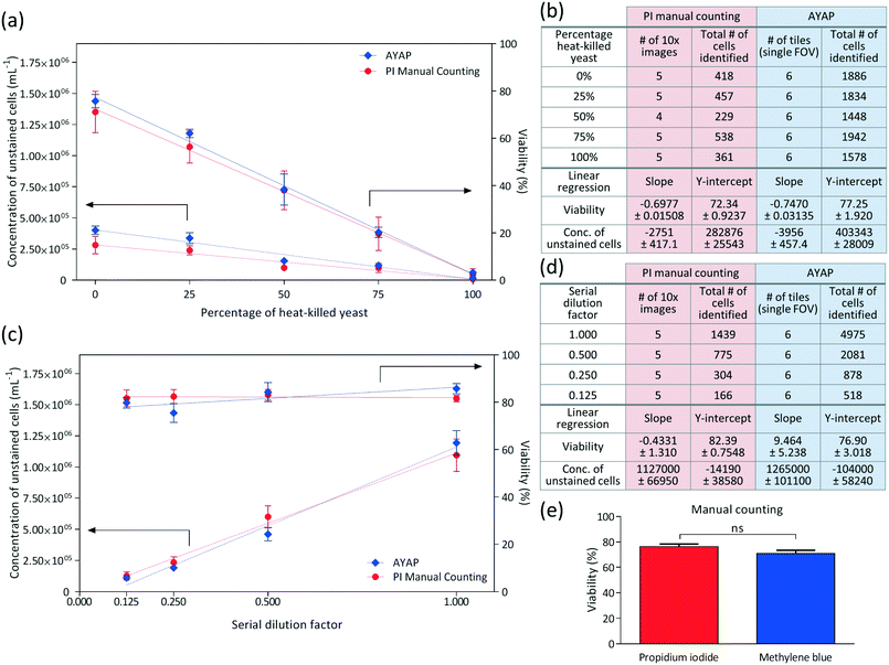
In these experiments, viability of the yeast cells was varied by mixing different ratios of heat-killed yeast with the original yeast solution, and linear regression analysis was performed for each method (i.e., AYAP using methylene blue vs. benchtop fluorescence microscopy using propidium iodide), the results of which are summarized in Fig. 5a and b. These results show that the AYAP measurements agree very well with the gold-standard fluorescence-based exclusion staining method. The slopes and Y-intercepts are also summarized in Fig. 5b, which further illustrate the similarity of the results of these two methods.
In order to test the performance of AYAP at various yeast concentrations, serial dilution was performed and analysed using linear regression (Fig. 5c and d). Once again, AYAP measurements agree well with the fluorescence-based exclusion stain within a concentration range of approximately 1.4 × 10⁵ to 1.4 × 10⁶ cells per mL. Above this concentration range, cell overlap and clumps increase, leading to measurement and cell counting inaccuracies (see e.g., Fig. S1†). Below this concentration range, on the other hand, the variability in concentration measurements due to statistical counting error increases, which is also shared by other microscopy based cell counting schemes due to the low number of cells per imaging FOV. Similarly, existing haemocytometers that are commonly used for laboratory and industrial applications claim accurate measurements between a minimum concentration of ∼2.5 × 10⁵ cells per mL and a maximum concentration of ∼8 × 10⁶ cells per mL,45 and samples with larger concentration of cells are diluted. For example, for fermentation applications, the yeast sample is typically diluted by a factor of 10 to 1000, prior to manual counting with a haemocytometer.8 Therefore, our platform's dynamic range of cell densities is quite relevant for various cell counting applications.
These results illustrate that the viability percentages and concentrations measured using AYAP are in close agreement to the gold-standard fluorescent staining method. The small differences between the two methods may be attributed to a few factors: (1) the channel height of our micro-fluidic chambers may slightly vary from test to test leading to changes in the sample volume, which may cause our comparisons to have some systematic error; and (2) our machine-learning algorithm currently ignores cell clumps, whereas in the manual counting results for the fluorescent stain, we also counted the cells within the clumps to the best of our ability.
In addition to these comparisons between AYAP and fluorescence based standard exclusion method, we also performed a control experiment to compare the viability percentages obtained from propidium iodide manual counting and methylene blue manual counting – both using a standard benchtop microscope to better understand and only focus on the differences between the two stains, everything else being same (Fig. 5e). For this goal, we divided our rehydrated yeast sample into six samples of equal volume. Three samples were stained via propidium iodide and three samples were stained via methylene blue. Five different 10× objective lens images were captured from each sample (fluorescence and bright-field for propidium iodide and methylene blue, respectively) and manually labelled. As seen in Fig. 5e, Mann–Whitney test46 was used as the statistical analysis method and no significant difference was observed between the viability percentages of these two staining methods.
We would like to emphasize that AYAP's design is cost-effective and field-portable as it approximately weighs 70 g (excluding the tablet-PC) and has dimensions of 4 × 4 × 12 cm. Furthermore, the viability stain used in our platform, methylene blue, is commercially available and does not require special storage conditions, making it especially appealing for field use. Furthermore, our platform allows for rapid assessment of yeast viability and concentration: it performs automatic labelling in 5–10 minutes when using auto-focusing mode and in <30 seconds in cases where auto-focusing is not needed. These processing times can be further improved by using more powerful tablet-PCs or laptops. In fact, to better put these computation times into perspective, the process of manual counting of some of our more confluent samples (see e.g., Fig. 5a–d) took more than an hour by lateral scanning using a benchtop microscope with a 10× objective lens.
AYAP achieves accurate yeast viability and concentration analysis because the on-chip nature of our microscopy platform allows imaging of a large FOV of ∼22.5 mm2 (see Fig. 4), which is more than an order of magnitude larger than the FOV of a typical 10× objective lens (1–2 mm2), and therefore it permits the analysis of a significantly larger number of cells in a short amount of time. Furthermore, our large imaging FOV is captured in less than 10 seconds, limiting the number of false positives associated with staining methods that expose cells to toxic environments. And finally, operator/user subjectivity is also eliminated in our system by using a machine-learning based statistical cell classification algorithm running on a tablet-PC.
Conclusions
We demonstrated a portable and cost-effective yeast viability and concentration analysis platform that uses a lens-free microscope and a trained machine-learning model to rapidly image a large FOV of ∼22.5 mm2 and automatically classify cells as live or dead. We used regression analysis in order to compare the performance of our platform against a fluorescence-based exclusion viability test and no significant difference between two methods was observed within a large cell concentration range of 0.14 million to 1.4 million cells per millilitre. This cost-effective device and computational method would be especially useful for the brewing and ethanol fuel production laboratories and industries.Conflicts of interest
A. O. is the co-founder of a company (Cellmic LLC) that commercializes computational microscopy, sensing and diagnostics tools.Author Contributions
A. F., A. G., and A. O. conceived the idea, A. F. and Y. Z. conducted the experiments and performed data analysis, A. G., M. L., R. Y. L. C., B. B., H. O., W. L., M. W. and Y. W. made contributions to experiments, microscope design, user interface design or data processing/analysis. A. F., Y. Z., and A. O. wrote the manuscript. A. O. supervised the project.Acknowledgements
The Ozcan Research Group at UCLA gratefully acknowledges the support of the Presidential Early Career Award for Scientists and Engineers (PECASE), the Army Research Office (ARO; W911NF-13-1-0419 and W911NF-13-1-0197), the ARO Life Sciences Division, the National Science Foundation (NSF) CBET Division Biophotonics Program, the NSF Emerging Frontiers in Research and Innovation (EFRI) Award, the NSF EAGER Award, NSF INSPIRE Award, NSF Partnerships for Innovation: Building Innovation Capacity (PFI:BIC) Program, Office of Naval Research (ONR), the Howard Hughes Medical Institute (HHMI), Vodafone Americas Foundation, and KAUST. This work is based upon research performed in a laboratory renovated by the National Science Foundation under Grant No. 0963183, which is an award funded under the American Recovery and Reinvestment Act of 2009 (ARRA).References
- U. E. B. Donalies, H. T. T. Nguyen, U. Stahl and E. Nevoigt, in Food Biotechnology, ed. U. Stahl, U. E. B. Donalies and E. Nevoigt, Springer Berlin Heidelberg, 2008, pp. 67–98 Search PubMed.
- E. J. Lodolo, J. L. F. Kock, B. C. Axcell and M. Brooks, FEMS Yeast Res., 2008, 8, 1018–1036 CrossRef CAS PubMed.
- I. S. Pretorius, Yeast, 2000, 16, 675–729 CrossRef CAS PubMed.
- J. Nielsen, Science, 2015, 349, 1050–1051 CrossRef CAS PubMed.
- L. C. Basso, H. V. de Amorim, A. J. de Oliveira and M. L. Lopes, FEMS Yeast Res., 2008, 8, 1155–1163 CrossRef CAS PubMed.
- H. V. Amorim, M. L. Lopes, J. V. de C. Oliveira, M. S. Buckeridge and G. H. Goldman, Appl. Microbiol. Biotechnol., 2011, 91, 1267–1275 CrossRef CAS PubMed.
- L. Caspeta, N. A. A. Buijs and J. Nielsen, Energy Environ. Sci., 2013, 6, 1077–1082 CAS.
- C. White and J. Zainasheff, Yeast: The Practical Guide to Beer Fermentation, Brewers Publications, Boulder, CO, 9/16/10 edn, 2010 Search PubMed.
- F. H. Lam, A. Ghaderi, G. R. Fink and G. Stephanopoulos, Science, 2014, 346, 71–75 CrossRef CAS PubMed.
- L. Caspeta, Y. Chen, P. Ghiaci, A. Feizi, S. Buskov, B. M. Hallström, D. Petranovic and J. Nielsen, Science, 2014, 346, 75–78 CrossRef CAS PubMed.
- S. E. Szabo, S. L. Monroe, S. Fiorino, J. Bitzan and K. Loper, Lab. Hematol., 2004, 10, 109–111 CrossRef CAS PubMed.
- D. Deere, J. Shen, G. Vesey, P. Bell, P. Bissinger and D. Veal, Yeast, 1998, 14, 147–160 CrossRef CAS PubMed.
- L. L. Chan, E. J. Lyettefi, A. Pirani, T. Smith, J. Qiu and B. Lin, J. Ind. Microbiol. Biotechnol., 2010, 38, 1109–1115 CrossRef PubMed.
- E. Scottberg, Pop. Mech., 2008 Search PubMed.
- L. Greenemeier, Sci. Am., 2008 Search PubMed.
- A. E. Farrell, R. J. Plevin, B. T. Turner, A. D. Jones, M. O'Hare and D. M. Kammen, Science, 2006, 311, 506–508 CrossRef CAS PubMed.
- Y. Sun and J. Cheng, Bioresour. Technol., 2002, 83, 1–11 CrossRef CAS PubMed.
- A. Greenbaum, W. Luo, T.-W. Su, Z. Göröcs, L. Xue, S. O. Isikman, A. F. Coskun, O. Mudanyali and A. Ozcan, Nat. Methods, 2012, 9, 889–895 CrossRef CAS PubMed.
- D. Tseng, O. Mudanyali, C. Oztoprak, S. O. Isikman, I. Sencan, O. Yaglidere and A. Ozcan, Lab Chip, 2010, 10, 1787–1792 RSC.
- A. Ozcan and E. McLeod, Annu. Rev. Biomed. Eng., 2016, 18, 77–102 CrossRef CAS PubMed.
- Z. Göröcs and A. Ozcan, IEEE Rev. Biomed. Eng., 2013, 6, 29–46 CrossRef PubMed.
- A. González Techera, S. Jubany, F. M. Carrau and C. Gaggero, Lett. Appl. Microbiol., 2001, 33, 71–75 CrossRef.
- J. G. Lewis, R. P. Learmonth, P. V. Attfield and K. Watson, J. Ind. Microbiol. Biotechnol., 1997, 18, 30–36 CrossRef CAS PubMed.
- M. de Barros Lopes, A. Soden, P. A. Henschke and P. Langridge, Appl. Environ. Microbiol., 1996, 62, 4514–4520 Search PubMed.
- S. Jubany, I. Tomasco, I. P. de León, K. Medina, F. Carrau, N. Arrambide, H. Naya and C. Gaggero, FEMS Yeast Res., 2008, 8, 472–484 CrossRef CAS PubMed.
- J. W. Goodman, Introduction to Fourier Optics, Roberts and Company Publishers, 2005 Search PubMed.
- O. Mudanyali, D. Tseng, C. Oh, S. O. Isikman, I. Sencan, W. Bishara, C. Oztoprak, S. Seo, B. Khademhosseini and A. Ozcan, Lab Chip, 2010, 10, 1417–1428 RSC.
- A. Greenbaum, N. Akbari, A. Feizi, W. Luo and A. Ozcan, PLoS One, 2013, 8, e76475 CAS.
- A. Greenbaum, A. Feizi, N. Akbari and A. Ozcan, Opt. Express, 2013, 21, 12469–12483 CrossRef PubMed.
- A. Greenbaum, Y. Zhang, A. Feizi, P.-L. Chung, W. Luo, S. R. Kandukuri and A. Ozcan, Sci. Transl. Med., 2014, 6, 267ra175 CrossRef PubMed.
- N. Cristianini and J. Shawe-Taylor, An Introduction to Support Vector Machines and Other Kernel-based Learning Methods, Cambridge University Press, 2000 Search PubMed.
- T. Hastie, R. Tibshirani and J. Friedman, in The Elements of Statistical Learning, Springer New York, 2009, pp. 417–458 Search PubMed.
- R. Kohavi, in Proceedings of the 14th International Joint Conference on Artificial Intelligence - Volume 2, Morgan Kaufmann Publishers Inc., San Francisco, CA, USA, 1995, pp. 1137–1143 Search PubMed.
- D. E. Pegg, Cryobiology, 1989, 26, 212–231 CrossRef CAS PubMed.
- W. Strober, in Current Protocols in Immunology, John Wiley & Sons, Inc., 2001 Search PubMed.
- J. R. Postgate, in Methods in Microbiology, ed. J. R. Norris and D. W. Ribbons, Academic Press, 1969, vol. 1, pp. 611–628 Search PubMed.
- J. T. Trevors, R. L. Merrick, I. Russell and G. G. Stewart, Biotechnol. Lett., 1983, 5, 131–134 CrossRef.
- J. Achilles, H. Harms and S. Müller, Cytometry, Part A, 2006, 69, 173–177 CrossRef CAS PubMed.
- M. Kwolek-Mirek and R. Zadrag-Tecza, FEMS Yeast Res., 2014, 14, 1068–1079 CAS.
- J. Inst. Brew., 1977, 83, 109–118 Search PubMed.
- S. S. Lee, F. M. Robinson and H. Y. Wang, Biotechnol. Bioeng. Symp., 1981, 11 Search PubMed.
- The Merck index: an encyclopedia of chemicals, drugs, and biologicals, ed. M. J. O'Neil, Merck, Whitehouse Station, N.J., 13th edn, 2001 Search PubMed.
- K. Smart, in Brewing Yeast Fermentation Performance, John Wiley & Sons, 2008, pp. 149–160 Search PubMed.
- S. M. Van Zandycke, O. Simal, S. Gualdoni and K. A. Smart, J. Am. Soc. Brew. Chem., 2003, 61, 15–22 CAS.
- D. Cadena-Herrera, J. E. Esparza-De Lara, N. D. Ramírez-Ibañez, C. A. López-Morales, N. O. Pérez, L. F. Flores-Ortiz and E. Medina-Rivero, Biotechnol. Rep., 2015, 7, 9–16 CrossRef.
- H. B. Mann and D. R. Whitney, Ann. Math. Stat., 1947, 18, 50–60 CrossRef.
Footnote |
| † Electronic supplementary information (ESI) available: Supplementary Fig. S1. See DOI: 10.1039/c6lc00976j |
| This journal is © The Royal Society of Chemistry 2016 |

