 Open Access Article
Creative Commons Attribution 3.0 Unported Licence
Nanoarchitectonics of metal oxide materials for sustainable technologies and environmental applications
Davide
Barreca
 a and
Chiara
Maccato
 *ab
*ab
aCNR-ICMATE and INSTM, Department of Chemical Sciences, Padova University, Via F. Marzolo 1, 35131 Padova (PD), Italy
bDepartment of Chemical Sciences, Padova University and INSTM, Via F. Marzolo 1, 35131 Padova (PD), Italy. E-mail: chiara.maccato@unipd.it; Tel: +39 049 8275234
First published on 20th June 2023
Abstract
Sustainable development compliant with environment and human health protection motivates researchers to explore green solutions towards improved economic and social wellbeing. These objectives, still very far from being achieved especially in developing countries, must necessarily be pursued through the tailored fabrication of low-cost, eco-friendly, efficient and stable multi-functional materials. In particular, nanostructures based on first-row transition metal oxides are amenable candidates for clean energy production, air purification and self-cleaning/anti-fogging purposes, especially if obtained through fabrication strategies allowing a careful modulation of their characteristics. In this highlight, after a brief introduction of the above issues, we provide selected representative examples of green oxide-based nanoarchitectures for the targeted end-uses. Attention is focused on the interplay between the material chemico-physical properties and the resulting functional performances, with the aim of providing some hints to control material behavior by design. In addition, we provide a critical outlook not only on the unique opportunities, but also on the main open challenges related to the use of the above multi-functional materials, in an attempt to stimulate further advancements in these emerging research areas.
1. Introduction
Over the last decade, the worldwide scientific community has been paying increasing attention to environment and human health protection. The synergistic actions necessary to meet the open challenges associated with the actual safety requirements1–5 are directly dependent on research activities enabling the protection and valorisation of the natural capital, an urgent global priority towards improved general welfare. In this regard, advancements in converging technologies enabling sustainable energy production, as well as purification processes yielding self-cleaning systems and facilitating the access to clean water/air, are a strategic and green requirement in alignment with the “Do No Significant Harm (DNSH)” principle.6 Progress in the related fields inevitably requires the implementation of viable solutions enabling social/industrial development with negligible environmental footprint.A first cornerstone is the decarbonization of the current energy portfolio to a cleaner and more sustainable one, a strategic goal to be pursued in alignment with the 2030 Agenda priorities.7 The replacement of fossil fuels with carbon-neutral alternatives is a key challenge to face climate changes and satisfy the ever-increasing global energy demand, accelerating the ecological transition dictated by public policies.8 In the framework of clean energy technologies, the (photo)production of molecular hydrogen, a strategically appealing energy vector, by water electrolysis, has drawn enormous attention to suppress the release of carbon dioxide and other contaminants produced by the extensive utilization of fossil fuels.4,9–12 The use of solar light, an inexhaustible and intrinsically renewable natural resource, to drive the electrolysis of seawater, the most Earth-abundant water reservoir (>95% of the total H2O), could open the door to a large-scale hydrogen integration in the energy models of a more sustainable society.9,13,14
A second major concern connected with the former one is the suppression of the ever-growing air contamination, especially in large cities and industrial areas. Among harmful atmospheric pollutants, nitrogen oxides (NOx, x = 1, 2), released daily into the atmosphere from fuel combustion and automobile exhausts, are the main source of various adverse effects,15 including photochemical smog, ozone layer depletion, and acid rain generation, along with various respiratory infections.16,17 To effectively achieve the elimination of breathable NOx in urban areas, heterogeneous photocatalysis assisted by sunlight, oxygen and water as natural resources holds outstanding promise.18,19 Similar photoactivated processes have been recognized as cost-effective and environmentally friendly routes even for:20,21 (a) the degradation of aqueous pollutants into harmless products, of particular importance due to the increasing water stress predicted by the Intergovernmental Panel on Climate Change (IPCC),22 and (b) the fabrication of smart stimuli-responsive systems featuring anti-fogging and, especially, self-cleaning properties for solid pollutant degradation, highly requested in various medical, industrial and technical contexts.23–26 Whereas the photodegradation of organic dyes in wastewater (a) has been the subject of several studies,5,27–31 the implementation of materials for case (b) featuring reversible hydrophobic/hydrophilic switching has been comparatively much less investigated.
The trait d'union that could significantly accelerate significant advancements in the target fields is the engineering of active and economically viable multi-functional catalytic platforms endowed with environmental friendliness and sufficient time stability.12 In order to empower enhanced sustainability from a greener perspective, the development of such materials in a supported form is a mandatory task: - to replace the state-of-the-art catalysts based on noble metals (such as the highly regarded Ru and Ir oxides), suffering from toxicity, supply shortage, high cost, and limited life cycle;3,10,32,33 - to substitute the largely employed powder-based materials, whose on-site utilization is prevented by the tendency to sinter/deactivate and inconvenient recovery processes after use.9,15,18,19,34 Despite the globally undertaken efforts, the implementation of stable and efficient systems still remains an open and challenging task. The modulation of material composition, structure, and morphology offers a broad perspective for property tailoring in the framework of nanoarchitectonics, an emerging paradigm in current nanomaterials science based on the synergistic combination of nanotechnologies with other specific disciplines to yield systems endowed with tailored information.35,36 Parallel studies have highlighted the interest in controllable material construction from nanosized units, a strategically appealing alternative to benefit from combined effects arising from the high active area, large defect content, enhanced light harvesting, and charge carrier confinement. Among the possible material classes, metal oxide based-nanosystems offer an extremely attractive playground bridging together the variety of properties of inorganic materials and the unique features of nanostructures.5,37–39 A careful modification of the latter by suitable preparation techniques represents a valuable tool to underpin advanced applications linked to safety and sustainability. Among the different routes, inherent advantages are offered by hydrothermal approaches,13,40,41 liquid phase processes,32,42,43 chemical vapor deposition (CVD),9,19,44 and template syntheses,45–47 the latter providing a unique way to produce nanoarchitectures with uniform dimensions.
In this widespread context, the present highlight aims at providing a brief overview on representative case studies related to supported metal oxides, eventually functionalized with dispersed metal or oxide activators, for sustainable energy generation through water splitting and photoactivated processes for: - NOx abatement, aimed at air purification; - anti-fogging and self-cleaning purposes (Fig. 1). The three targeted applications are connected by the key importance in triggering technology progress towards an improved environmental safeguard, and by the possibility of using controlled irradiation to activate the involved processes. In particular, in this manuscript the attention is intentionally paid to supported nanostructures based on eco-friendly, cost-effective, and abundant first-row transition metal oxides (Mn2O3, MnO2, Fe2O3, ZnO). The latter are considered either as such, or combined with suitable agents in nanocomposites/nanoheterostructures, benefitting from the combination of the single constituents to yield a superior functional behaviour. The examples examined herein encompass various kinds of nanomaterials, with no systematic attempt to cover the whole pertaining literature work. In fact, since an endless range of nanoarchitectures can be virtually fabricated, the aim of this contribution is far from providing a detailed technical review, but rather to deliver an author's perspective on representative research activities actually in the spotlight to mitigate the environmental concern through the use of non-toxic systems. To this aim, our main purpose is to describe selected relevant milestones, as well as open issues still hindering real-world utilization. In the end, perspectives for future developments are also briefly summarized.
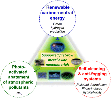 | ||
| Fig. 1 Schematic overview of the materials targeted in the present highlight and the pertaining functional applications. | ||
2. Energy conversion: oxygen evolution reaction in water splitting
Molecular hydrogen, an attractive energy carrier with high efficiency, is expected to play an important prospected role in supporting mankind on the road to carbon neutrality.34,48,49 Nonetheless, at present H2 is mainly obtained from fossil fuel reforming processes (‘grey hydrogen’),50 without capturing the released greenhouse gases. ‘Blue hydrogen’ is essentially the same as grey hydrogen, but with capture and storage of the released CO2. Though being typically regarded as a low-carbon fuel, ‘blue hydrogen’ requires a considerable amount of energy for its production, which renders it expensive. In order to go “out of the blue”, the solution is offered by ‘green hydrogen’,50 generated using carbon-free electricity (in perspective, either wind-based or from photovoltaics) for water splitting. The latter, possibly activated by illumination, is indeed an outstanding alternative for H2 generation free from any ecological footprint.51–56 In general, (photo)electrochemical water splitting involves two different half-reactions occurring at interconnected electrodes (Fig. 2). Electrons released in the oxygen evolution reaction (OER) at the anode, typically based on an n-type semiconductor,57,58 are transferred through an external circuit to the counter-electrode, a metal or a p-type semiconductor (cathode).59 At the interface of the latter with the electrolyte, electrons can directly take part in the hydrogen evolution reaction (HER).57,60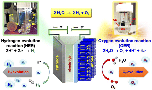 | ||
| Fig. 2 Sketch of an electrochemical cell for water splitting, with indication of the cathodic and anodic processes. Digital photographs of cells used for electrochemical tests are also reported. WE = working electrode; RE = reference electrode; CE = counter-electrode. Reproduced with permission from ref. 33 and 60. Copyright 2011, Wiley-VCH, and 2020, The Royal Society of Chemistry, respectively. | ||
Nevertheless, H2O splitting is a thermodynamically up-hill process involving a large Gibbs free energy positive change (ΔG° = 237 kJ mol−1).49,59,61 In particular, the bottleneck limiting its overall efficiency is the anodic OER, a four-electron process for the evolution of one O2 molecule,4,11,12,57,62 which is both kinetically and thermodynamically demanding. As a consequence, eco-friendly and highly-efficient electrocatalysts enabling to reduce the overpotential and expedite the reaction kinetics are requested as an alternative to the state-of-the-art RuO2 and IrO2 ones.3,32 Accordingly, water electrolysis to yield green hydrogen has been investigated in freshwater comprising acid, base or buffer systems,52,63–66 and is a satisfactory way to obtain sustainable energy using accessible electricity as a driving force.
The key indicators for OER functional performances of the target catalysts are the delivered current density, the overpotential [typically calculated as the difference between the experimental potential value at 10 (or 100) mA cm−2 and the thermodynamic potential for O2 evolution (1.23 V)9], and the stability upon prolonged testing, of crucial importance for practical end-uses. In the current tide of studies on related topics, a valuable example of OER electrocatalysts based on green and earth-abundant elements is provided by Fe2O3@CuO core–shell nanotube heterostructures.32 The target materials, prepared by a multi-step strategy (see the caption for Fig. 3), were characterized by an even distribution of nanotubes with an open-ended structure (Fig. 3a and b) conformally covering the underlying Cu foam. The analyses revealed an even distribution of Cu and Fe over the inner and outer nanotube walls, respectively (Fig. 3c and d), evidencing thus the Fe2O3 shell and CuO core structure. Photoelectron spectroscopy characterization confirmed the presence of such oxides and the formation of heterojunctions, leading to electronic structure modulation of both CuO and Fe2O3 thanks to the nanometric spatial organization (Fig. 3c).
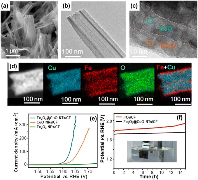 | ||
| Fig. 3 (a) Scanning electron microscopy (SEM) image of Fe2O3@CuO heterostructured core–shell systems. The nanomaterials were in situ grown from a copper foam (CF) through a liquid-phase route involving the initial formation of CuO nanorods (NRs), subsequent functionalization with Fe2O3 nanoparticles (NPs) and final annealing in air. Representative transmission electron microscopy (TEM) (b) and high resolution (HR)-TEM (c) images of Fe2O3@CuO nanotubes (NTs). (d) Energy dispersive X-ray spectroscopy (EDXS) Cu, Fe, and O elemental mapping of a single Fe2O3@CuO nanotube, along with an overlaid Fe and Cu image. (e) Linear sweep voltammetry (LSV) curves of Fe2O3@CuO NTs/CF recorded in 1.0 M KOH solutions. (f) Chronopotentiometric analysis of Fe2O3@CuO NTs/CF and IrO2/CF at 100 mA cm−2 for 15 h (inset: digital photograph of oxygen bubbles evolved at the electrode surface during the process). Reprinted with permission from ref. 32. Copyright 2020, American Chemical Society. | ||
Fig. 3e compares the linear sweep voltammetry curves of single phase and heterostructured systems. The recorded data indicated that Fe2O3 and CuO needed an overpotential of 724 and 433 mV, respectively, to reach 100 mA cm−2, against a value of only 398 mV for Fe2O3@CuO. The latter, lower than that of the benchmark OER IrO2 catalyst, highlighted the attractive behavior of Fe2O3@CuO, better than those of various Cu-based electrocatalysts supported on foam substrates.32 This result can be traced back to the high material active area, as well as to the electronic interplay between the single heterostructure components. The latter, in turn, tuned the system electronic structure, influencing the reactant adsorption strength and the energy barriers of the various process steps, resulting ultimately in a favorable improvement of the OER kinetics.32
Chronopotentiometric tests (Fig. 3f) evidenced a high electrocatalyst durability, of great importance for practical real-world applications.
In comparison to a reference IrO2-based electrode, Fe2O3@CuO NTs/CF displayed a negligible potential variation during prolonged electrochemical testing at high current density. This long-term stability under harsh operational conditions, confirmed also by post-operando chemico-physical analyses, opens up amenable opportunities for an eventual engineering of the target electrocatalysts.
Attractive advantages in this regard can be also offered by a joint natural capital exploitation, with regard to the use of seawater and solar radiation.14,67–70 In fact, seawater electrolysis could be activated by sunlight and renewable electricity in energy-rich coastal/arid regions, yielding a sustainable H2 production of key importance for the future energy landscape.13,14 In this context, Li et al.13 have focused on the fabrication of Fe2O3/WO3 nanorod arrays on conducting glass substrates using a controllable and cost-effective preparation procedure sketched in Fig. 4a. As can be observed in Fig. 4b, the adopted route enabled the fabrication of dense Fe2O3 NR arrays (average diameter ≈ 200 nm). The introduction of WO3 resulted in a slight increase of the NR diameter and in the formation of more rounded and interconnected tips (Fig. 4c). The Fe2O3/WO3 X-ray diffraction patterns (Fig. 4d) confirmed the obtainment of phase-pure Fe2O3 and WO3, excluding the occurrence of ternary phases. These results, along with the outcomes of additional TEM analyses, demonstrated the presence of Fe2O3/WO3 heterostructures, enabling an enhanced separation of photogenerated charge carriers.13 In fact, photoelectrochemical functional tests performed on the target electrocatalysts (Fig. 4e) revealed a rapid photo-response in the whole potential interval over several on–off cycles. As concerns the Fe2O3/WO3 heterocomposite, the photocurrent onset was recorded at 0.59 V, and the system displayed appreciably higher performances in comparison to the single oxide counterparts, yielding 1.03 mA cm−2 at 1.23 V. This enhancement was in fact attributed to the interfacial formation of Fe2O3/WO3 heterojunctions, minimizing detrimental electron–hole recombination.13,21 Notably, tests carried out on the same materials in photoelectrochemical splitting of natural seawater yielded almost the same photocurrent density values as those of Fig. 4e, indicating that these electrocatalysts can effectively sustain seawater photosplitting. The system photoresponse, tested by photocurrent–time measurements in natural seawater at 1.23 V vs. RHE, revealed that Fe2O3/WO3 heterostructures maintained ≈65% of the initial value after continuous illumination for 5 h, a key point in view of eventual large-scale implementation.
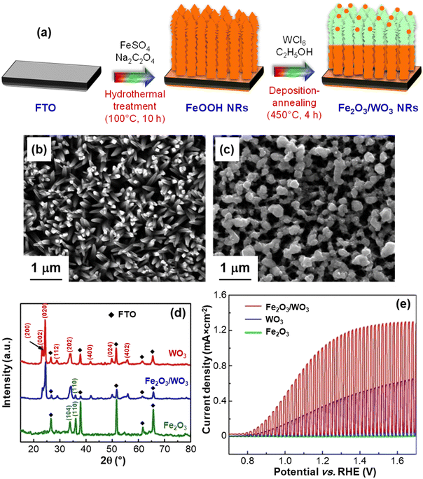 | ||
| Fig. 4 (a) Hydrothermal route and deposition-annealing process for the growth of Fe2O3/WO3 NRs on fluorine-doped tin oxide (FTO) glass substrates. Top-view SEM micrographs of Fe2O3 (b) and Fe2O3/WO3 nanorods (c). (d) X-ray diffraction (XRD) patterns of Fe2O3 NRs, Fe2O3/WO3 NRs, and WO3 films. (e) Chopped photocurrent density vs. potential plots for the same systems, recorded in 0.1 M Na2SO4 aqueous solutions under 100 mW cm−2 (AM 1.5G) illumination. Reprinted with permission from ref. 13. Copyright 2016, Elsevier. | ||
Recently, our research group reported on the fabrication of seawater oxidation electrodes based on manganese(III) oxide nanocomposites with Fe2O3 and Co3O4, well-known OER catalysts.9 Such materials, developed by a multi-step plasma-assisted process, featured a close contact between Mn2O3 and the functionalizing agents (Fig. 5a and b), as demonstrated by the dispersion of Fe2O3 and Co3O4 even into the inner Mn2O3 deposit regions. This enables the materials to benefit from the mutual component interplay to boost the resulting electrocatalytic activity. Regarding the Co3O4-containing material (Fig. 5b), differently from the Fe2O3 case, the outermost sample regions were Co-rich, a phenomenon directly influencing the ultimate electrocatalytic activity, as discussed below. The Mn2O3 deposit was characterized by the assembly of high area dendritic structures (Fig. 5c and d), in close contact with Fe2O3 or Co3O4 nanoaggregates (mean dimensions ≈ 8 and 4 nm, respectively). Electrochemical tests in simulated seawater evidenced higher current densities (Fig. 5e) and lower overpotentials for the composite systems in comparison to the corresponding single phase oxides (e.g., 490/450 mV for Fe2O3–Mn2O3/Co3O4–Mn2O3 against 500 mV of Mn2O3).9 The obtained performances, comparing favorably with previously reported ones for manganese oxide-based systems, could be ascribed both to the intrinsic OER catalytic activity of Fe2O3 and Co3O4 and to the formation of oxide/oxide heterojunctions, yielding improved charge carrier separation. An additional effect accounting for the better Co3O4–Mn2O3 performances was the different in-depth distributions of Fe2O3 and Co3O4 (see above and Fig. 5a and b). In fact, although the more even dispersion of the former can be deemed to promote a closer contact with Mn2O3 boosting functional activity, the formation of pH gradients during OER around Fe2O3 nanoparticles in the inner Mn2O3 regions counterbalances this effect.9 Consequently, the OER activity of Fe2O3–Mn2O3 is reduced in comparison to Co3O4–Mn2O3. Chronoamperometric tests (Fig. 5f) evidenced that, after an initial transient period, all the materials exhibited good stability, in particular the Co3O4–Mn2O3 one. Additional analyses and iodometric titration data9 ruled out the presence of hypochlorite traces (compare the pale pink reference solution and the colorless OER solution, Fig. 5g and h), indicating a remarkable selectivity towards O2 production against Cl2 evolution. The proposed catalyst combinations pave the way to the implementation of cost-effective electrodes for seawater splitting to H2, an open challenge of key relevance for a real-world end-use.
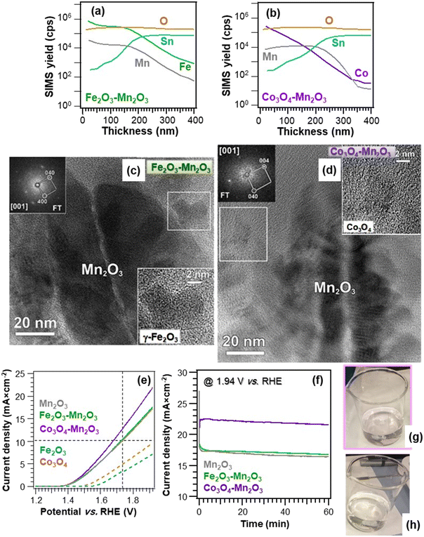 | ||
| Fig. 5 Secondary ion mass spectrometry (SIMS) depth profiles of Fe2O3–Mn2O3 (a) and Co3O4–Mn2O3 deposits (b) obtained by plasma enhanced-chemical vapor deposition (PE-CVD) of manganese oxides on FTO, functionalization with Fe2O3 and Co3O4 by sputtering, and final annealing under an Ar atmosphere. (c) HR-TEM image of an Fe2O3–Mn2O3 specimen. The white box marks a single Fe2O3 particle, whose enlargement is given as an inset. The corresponding Fourier transform (FT) pattern ([001] zone axis) in the upper left corner highlights the occurrence of cubic γ-Fe2O3 polymorph. (d) HR-TEM image of a Co3O4–Mn2O3 sample. The white box marks a single Co3O4 nanoparticle, whose enlargement is provided as an inset. The corresponding FT pattern ([001] zone axis) in the top left corner indicates the presence of cubic Co3O4. (e) LSV curves of the target materials registered in simulated alkaline seawater. The curves for bare Fe2O3 and Co3O4 are also reported. Vertical and horizontal dashed lines correspond to an overpotential of 500 mV and a current density of 10 mA cm−2, respectively. (f) Chronoamperometry curves of Mn2O3-based electrodes in simulated alkaline seawater recorded at 1.94 V vs. RHE. Digital photographs of the reference solution (2.0 × 10⁻⁷ M, pale pink) (g) and working solution (colourless) (h) in the iodometric titration for the identification of possible hypochlorite species generated during the OER, showing the absence of ClO− production in case (h).9 Reprinted with permission from ref. 9. Copyright 2021, Elsevier. | ||
3. Air purification: NOx abatement
As already mentioned, the damages resulting from nitrogen oxide release into the outer atmosphere are a cause of great concern. Although environmental USA and EU agencies limit the hourly allowed NOx air concentration to 0.1 ppm and 0.2 ppm,16 these values are hardly attained, especially in highly populated cities, and NOx emissions are responsible for thousands of early deaths worldwide.17,42,71,72 These issues have significantly stimulated the interest in heterogeneous photocatalysis involving the use of solar light, oxygen and water as natural resources for an efficient NOx removal from the atmosphere (De-NOx).73–76 The photo-activated De-NOx process promoted by a suitable semiconductor (SC) material is sketched in Fig. 6 and can be described as follows:19,42,71,72| SC + hν → h+ + e− | (1) |
| h+ + H2O → ˙OH + H+ | (2) |
| e− + O2 → ˙O2− | (3) |
| NO + ˙O2− → NO3− | (4) |
| NO + ˙OH → HNO2 | (5) |
| HNO2 + ˙OH → NO2 + H2O | (6) |
| NO2 + ˙OH → NO3− + H+ | (7) |
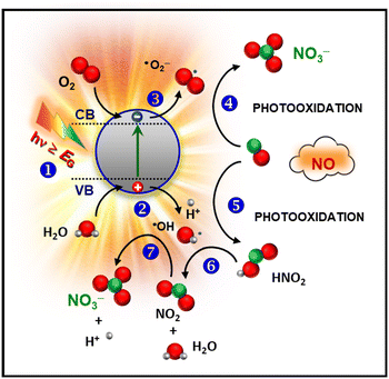 | ||
| Fig. 6 Simplified sketch of the mechanism of photocatalytic NO oxidation promoted by a semiconducting material. | ||
First, illumination with radiation of suitable wavelength (step 1) results in the formation of electron–hole pairs, which can reach the material outermost surface and trigger the involved redox processes. In particular, photogenerated charge carriers can react with water and oxygen molecules [stages (2) and (3)], yielding the formation of reactive oxygen species (ROS), the main actors of the whole process. The resulting ˙O2− promotes NO oxidation to nitrate species (4). In parallel, ˙OH radicals can also trigger NO3− formation through the intermediate oxidation steps NO → HNO2 → NO2 → NO3− [stages (5), (6), and (7)].16 In this regard, efforts have been focused on the complete oxidation to harmless nitrate species, minimizing the release of NO2, an intermediate even more toxic than NO.17,74,77,78 Hence, in a sustainable De-NOx process, an important goal is the obtainment not only of the highest NO conversion efficiency, but even of the best selectivity, expressing the ratio of degraded NO completely converted into harmless nitrate rather than into toxic NO2. These features have to be hopefully accompanied by a good photocatalyst service life.
The majority of studies in this field have so far focused on the use of TiO2, but the corresponding processes suffer from a low efficiency due to its large band gap (EG ≈ 3.2 eV), requiring activation by UV light, which accounts for only 4% of the solar spectrum.15–17,78–82 Furthermore, TiO2 may be carcinogenic when inhaled.42 These issues have significantly boosted the attention towards alternative eco-friendly materials, such as ZnO, whose performances can also be improved through the construction of heterostructures83–87 in terms of extended light absorption and improved electron–hole separation.74,88,89
In this context, the group of Sanchez et al. has recently proposed a sustainable and efficient De-NOx photocatalyst based on ZnO supported on rice husk, an agricultural low-cost waste product successfully used as a green raw material.42 The target systems, prepared by a straightforward synthetic procedure (summarized in the caption of Fig. 7), were characterized by the uniform coverage of the cob-shaped skeleton by crystalline ZnO agglomerates (70–180 nm; Fig. 7a–d). The annealing duration (2 vs. 4 h) did not appreciably influence the ZnO morphology (compare Fig. 7a–c with Fig. 7b–d). The skeleton acted as a support for the growth of zinc oxide particles, which, in the case of systems obtained by milling (see caption for Fig. 7), were organized in amorphous and larger aggregates (sizes up to 280 nm). The beneficial effect of rice husk was also confirmed by the surface area, which dropped from 40–53 m2 g−1 to <5 m2 g−1 for bare ZnO reference specimens.42
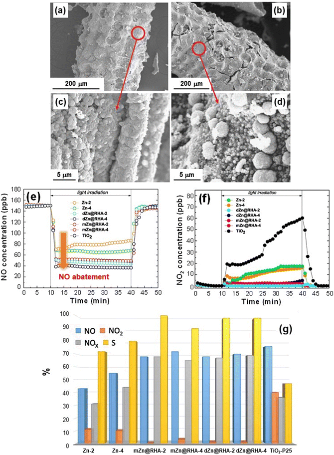 | ||
| Fig. 7 (a–d) SEM images for ZnO deposited on rice husk (RH) supports. The materials were obtained by liquid phase deposition from Zn(II) acetate on RH and final annealing at 600 °C for 2 h (dZn@RHA-2, (a) and (c)) and 4 h (dZn@RHA-4, (b) and (d)). (e and f) Nitrogen oxide concentration profiles obtained upon artificial sunlight illumination (UV-vis) for dZn@RHA, mZn@RHA and Zn samples. mZn@RHA-2 and mZn@RHA-4 samples were obtained from milling of Zn(II) acetate and RH, and calcined at 600 °C for 2 or 4 h. The curves pertaining to reference ZnO samples (Zn-2 and Zn-4, treated for 2 or 4 h) and commercial TiO2 P25 (Evonik)® are also shown. (g) Bar plot (%) of NO conversion (blue), released NO2 (orange), NOx conversion (grey; [NOx] = [NO] + [NO2]) and selectivity (yellow) for the target photocatalysts. The selectivity (%) is defined as {([NOx]in − [NOx]out)/[NOx]in} × 100/{([NO]in − [NO]out)/[NO]in}, where [NO]in and [NOx]in and [NO]out and [NOx]out are the inlet and outlet concentrations, respectively.42,74,78 Reprinted with permission from ref. 42. Copyright 2019, Elsevier. | ||
When the systems were illuminated, nitrogen monoxide degradation was observed, as confirmed by the rapid drop of NO concentration profiles, which reverted to the original values when irradiation was turned off (Fig. 7e). The analysis revealed that the NO conversion efficiency was related to the sample surface area, being ≈75% for the composite samples [and commercial TiO2 P25 (Evonik), tested for comparison] and decreasing to ≈50% for the bare ZnO reference samples (Fig. 7e). The release of highly toxic NO2 (Fig. 7f) was directly dependent on material nature. In the case of TiO2 P25, NO2 emission underwent a progressive increase under illumination, in line with previous literature data.90 In a different way, NO2 formation was inhibited for bare ZnO and became negligible for the ZnO systems supported on rice husk.
Fig. 7g compares the NO conversion and NO2 emission with the corresponding selectivity for the various specimens. The remarkable selectivities (>70% for ZnO on RH), accompanied by a high NOx conversion (≈70%), outperform the TiO2 P25 reference and compare very favorably with literature reports.42 These results can be traced back to the influence of the used support on ZnO growth, enabling the achievement of higher surface areas which, in turn, favor the accessibility of reactive sites to gaseous molecules. These results, along with the biosafe character, low cost and reusability of the developed photocatalysts, as well as the straightforward preparation route, are highly appealing for their eventual utilization in real-world air purification.
Another example of ZnO-based materials for De-NOx applications concerns the development of FTO-supported ZnO–WO3 nanoheterostructures by CVD of ZnO, followed by WO3 dispersion by sputtering.77 X-ray photoelectron spectroscopy (XPS) analyses (Fig. 8a and b) yielded Zn 2p3/2 binding energies (BEs) of 1021.8 and 1022.3 eV, respectively, for bare ZnO and ZnO–WO3, suggesting a ZnO → WO3 electron transfer in the latter,92–97 as confirmed by the W 4f7/2 BE (35.5 eV), slightly lower than typical WO3 values.98–100 These issues have a direct impact on material performances (see below and Fig. 8h). SIMS analysis (Fig. 8c) highlighted that in-depth tungsten distribution was nearly parallel to the zinc one. The high intermixing of the two oxides, advantageous to guarantee an intimate contact yielding a high density of heterojunctions, was efficiently achieved thanks to the inherent sputtering infiltration power, especially into open area systems as the present ZnO ones.9,37,77 In fact, morphological investigation (Fig. 8d and e) evidenced the formation of porous deposits (thickness = 180 nm, root-mean-square roughness ≈ 55 nm), with no appreciable modifications in comparison to the pristine ZnO. Photocatalytic tests indicated that, whereas in the dark no degradation occurred, NO removal rapidly increased upon illumination for both specimens (Fig. 8f), revealing a higher activity for ZnO–WO3. The latter was also more selective than bare ZnO in promoting the complete NO photo-oxidation to nitrate species (Fig. 8g). The total NOx removal values were estimated to be 2960 and 2300 ppm m−2 for ZnO–WO3 and bare ZnO, respectively. The beneficial performance improvement induced by ZnO functionalization with WO3 was attributed to an enhanced electron–hole separation promoted by the effective coupling of the two oxides.93,101,102 Owing to the different positions of valence and conduction band edges of the single oxides (Fig. 8h), excited electrons can in fact be transferred from ZnO to WO3 (as demonstrated by XPS, see above), while holes flow in the opposite direction.91,92 Hence, electrons and holes accumulate in the WO3 CB and ZnO VB, respectively, promoting O2 reduction and H2O oxidation to yield ˙O2− and ˙OH, the main De-NOx active species.
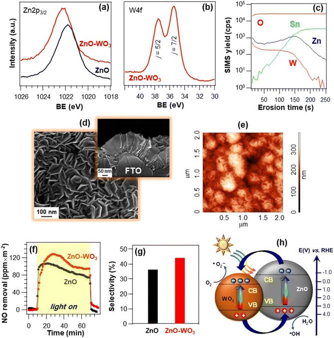 | ||
| Fig. 8 W 4f (a) and O 1s (b) photoelectron peaks for ZnO nanomaterials and ZnO–WO3 nanoheterostructures supported on FTO substrates. The systems were prepared by the initial CVD of ZnO, and the subsequent WO3 introduction by sputtering.77 (c) SIMS depth profile for a ZnO–WO3 specimen. (d) Representative plane-view and cross-sectional SEM (d) and AFM (e) micrographs of ZnO–WO3. (f) NO removal vs. time and (g) the corresponding NO abatement selectivity (g) for the same specimens under irradiation with artificial sunlight (UV-vis). Experiments were performed under a continuous NO supply of 150 ppb. Selectivity is defined as in Fig. 7. (h) Schematic band energy diagram for ZnO–WO3 heterostructures and the corresponding charge carrier separation under UV-vis illumination. Reproduced with permission from ref. 77 and 91. Copyright 2018, The Royal Society of Chemistry, and Elsevier, 2013, respectively. | ||
The proposed fabrication strategy can be successfully adapted to a variety of supports, as well as extended to the preparation of other photoactive hetero-composite architectures. In this regard, a representative example is provided by supported nanostructures based on the less studied β-Fe2O3 polymorph, utilized for the first time as a De-NOx photocatalyst. The systems were obtained by the CVD of β-Fe2O3 on Si substrates, followed by functionalization with CuO by sputtering (caption for Fig. 9).18 XPS analyses revealed that, for bare Fe2O3, the Fe 2p peak position [BE(Fe 2p3/2) = 711.2 eV] matched the β-iron(III) oxide value,15,34,103 whereas it underwent a small downward shift for Fe2O3–CuO (Fig. 9a). This variation, in conjunction with the Cu 2p BE slightly higher than for CuO [BE(Cu 2p3/2) = 934.0 eV, Fig. 9b], highlighted the occurrence of a CuO → Fe2O3 electron transfer at Fe2O3/CuO interfaces. The O 1s photopeak (Fig. 9c) resulted from the contribution of a main band, due to lattice O (I), and a second signal due to O species chemisorbed on oxygen vacancies (II).104 The latter can favorably promote a higher reactivity in NO chemisorption, being thus beneficial for De-NOx applications.83 Material morphology was characterized by an even distribution of faceted pyramids, whose assembly yielded an open structure (Fig. 9d). This feature anticipated attractive performances thanks to the high contact area with the reaction environment, helpful even for radiation-induced charge transfer at the material surface.5,15,81 As shown in Fig. 9e, after 1 h illumination, a NO removal of 20 ppm m−2 was measured for Fe2O3–CuO, an appreciably superior value in comparison to the single oxides. In addition, the negligible release of gaseous NO2 highlighted the advantages featured by nano-heterostructured systems for De-NOx processes selective towards NO3− formation.
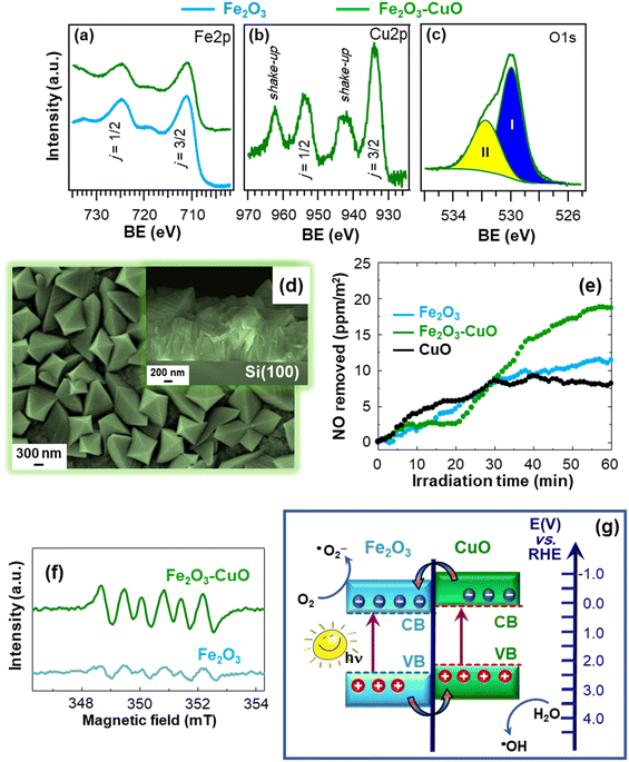 | ||
| Fig. 9 Fe 2p (a), Cu 2p (b) and O 1s (c) photoelectron peaks for Fe2O3 and Fe2O3–CuO nanoheterostructures supported on Si substrates. The occurrence of CuO was confirmed by the presence of shake-up peaks. The materials were fabricated by CVD of Fe2O3 and functionalization with CuO by sputtering. (d) Plane-view and cross-sectional (inset) SEM images of Fe2O3–CuO. (e) Concentration profiles obtained during NO photodegradation for Fe2O3 and Fe2O3–CuO upon artificial sunlight illumination (UV-vis). The curve for bare CuO is also shown for comparison. (f) Electron paramagnetic resonance (EPR) spectra of Fe2O3 and Fe2O3–CuO registered in a 45 mM methanolic solution of the spin-trapping 5,5-dimethyl-1-pyrroline N-oxide agent (DMPO), for ˙O2− detection. (g) Schematic representation of the type-II heterojunction energy band diagram for Fe2O3–CuO (approximate energy levels on the RHE scale). Reprinted with permission from ref. 18. Copyright 2022, Elsevier. | ||
To attain a deeper understanding of the occurring process, EPR analyses were carried out. As observed in Fig. 9f, the intensity of the sextet corresponding to the formation of the DMPO–˙O2− adduct83 (undetectable in the dark) underwent an increase for Fe2O3–CuO in comparison to bare Fe2O3. This phenomenon revealed an enhanced ˙O2− generation for the heterocomposite catalyst, accounting for the improved performances in NO removal. Additional analyses evidenced that the target photocatalysts can generate even ˙OH radicals. The enhanced ROS formation for Fe2O3–CuO confirmed the formation of heterojunctions between the single oxides and, in particular, the occurrence of electron transfer phenomena, which can be interpreted based on a type-II charge transfer mechanism (Fig. 9g).105 Briefly, irradiation of both Fe2O3 and CuO yields electron excitation and subsequent transfer from CuO to the Fe2O3 conduction band, while holes are accumulated in the CuO valence band. Accordingly, charge carrier recombination is suppressed and photogenerated electrons and holes can effectively promote the formation of ˙O2− and ˙OH. Overall, these studies broaden the perspectives of photocatalytic NO oxidation, providing useful guidelines for the nano-engineering of active and economically viable supported photocatalysts for air purification.
4. Anti-fogging and self-cleaning platforms: smart light-responsive systems
The last application field dealt with in the present manuscript concerns the design and fabrication of the so-called smart materials, which are basically light stimuli-responsive nanosystems exhibiting anti-fogging and self-cleaning properties of interest in different practical and industrial contexts.106The phenomena underlying such end-uses are photo-induced hydrophilicity (PH) and photocatalytic oxidation (PCO) processes, which are, respectively, the basis of anti-fogging and self-cleaning systems. As sketched in Fig. 10, both PH and PCO involve as the first step the photo-excitation of a suitable semiconductor, yielding the formation of electron–hole pairs. The subsequent fate of these charge carriers critically determines the overall material activity.25,107 In the case of PH (Fig. 10, left side), photogenerated electrons and holes can react with lattice metal centers and bridging O surface species, respectively. As reported for TiO2 and ZnO,23,24,106,108 this behaviour results in the formation of reduced metal defective sites and O vacancies, which play an important role in the subsequent events. In fact, water exposure induces the formation of hydroxyl groups chemically bonded to the material surface, rendering it hydrophilic, with important practical outcomes. Upon sufficiently long system storage in the dark, the wettability is slowly reconverted to the initial hydrophobic state109 through a progressive decrease of the surface –OH group content. In a different way, in the case of PCO, photogenerated electrons and holes separately travel to the semiconductor surface and interact with surface species (oxygen and organic pollutants), resulting in the photo-induced oxidation of the latter (i.e., the degradation of surface contaminants).25
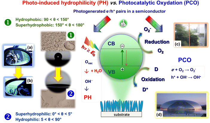 | ||
| Fig. 10 Schematic representation of the processes involved in the photo-induced hydrophilicity and photocatalytic oxidation processes activated by a semiconducting material. The left panel presents two digital photographs of an automotive side view mirror, uncoated (a) and coated (b) with TiO2, demonstrating the anti-fogging effect. The right panel photographs provide two examples on the use of self-cleaning coatings. (c) Window at the museum of photocatalysis in the Academy of Sciences and technology, Kanagawa, Japan. A self-cleaning TiO2 coating is absent and present on the left and right glass sides, respectively. (d) National Centre for Performing Arts, Beijing, China, coated with self-cleaning materials. Reproduced with permission from ref. 24 and 106. Copyright 2012, The Royal Society of Chemistry, and Springer Nature, 2021, respectively. | ||
The effective tuning of surface wettability via combined chemical/structural modifications has been the subject of interest for several applications.23,110 An important example is offered by anti-fogging coatings, since fogging nuisance is ubiquitous on eyeglasses, ski/SCUBA goggles, and rearview mirrors (Fig. 10a and b).23,109,111 In addition, surface fog decreases the efficiency of analytical/medical instruments and accounts for production capability losses in greenhouse windows, solar energy arrays, and buildings.110,111 In fact, the combination of PH and PCO functionalities has been utilized to develop anti-fogging and self-cleaning systems for automotive glasses, optics, energetics, furniture, and constructions.106,112 In a nutshell, illumination can decompose the dirt and render the material surface (super)hydrophilic. Subsequently, water, for example from rain, spreading on the surface, can produce the desired “contaminant washing”, resulting thus in the target self-cleaning effect (see for instance Fig. 10c and d).
On a laboratory scale, PH and PCO functionalities can be tested by simply monitoring variations of the water contact angle on the surface of the target materials as a function of illumination time.25,26,44 In fact, irradiation results in a progressive decrease of the contact angle even in the presence of solid contaminants, whose photodegradation induces a hydrophobic-to-hydrophilic transition. A key parameter determining material performances is hence the overall variation of the measured contact angle between the (super)hydrophobic and (super)hydrophilic states, which is required to be as fast as possible upon application of external stimuli. In addition, the reversibility in the recovery of the original state can be considered as an indirect fingerprint of the system stability.
Various studies have examined the process theoretical background,23,106,108,110,113 and it has been demonstrated that wetting properties are directly connected with the system nano-texture,25,26,113,114 whose tailoring is a powerful tool to control and modulate such features by design. As for De-NOx photocatalysts, the most investigated material is TiO2,24,106,112,113 but an attractive alternative is offered by nanostructures of ZnO, either as such or combined with suitable semiconductors/metals.26,77,108,109 An interesting example is provided by the work of Wei et al. on ZnO NR arrays coated with gold NPs under different conditions.40 TEM analyses evidenced that the adopted strategy (caption for Fig. 11) resulted in an even dispersion on ZnO of small-sized gold NPs (5–10 nm; Fig. 11a–c). An increase in the sputtering time enabled a parallel increase in the size of Au NPs, and the system wettability could be tailored accordingly (Fig. 11d–h). In fact, water droplets can penetrate only partially into bare ZnO NR arrays, due to their much larger dimensions in comparison to the NR size and mutual distance. As a result, the droplets come into contact with both ZnO NRs and trapped air, resulting in a hydrophobic surface state (Fig. 11e). The introduction of Au NPs produces a contact angle reduction for an Au sputtering time of 30 s, followed by a subsequent increase (Fig. 11d). This behavior was traced back to the presence of a hierarchical structure with dual-scaled characteristics, i.e. large (ZnO NR arrays and the inter-NR distance with a size of ≈100 nm) and small (surface-attached gold NPs, with a few nm size), as shown in Fig. 11f–h. Since water droplets are much larger than Au NPs, they exhibit an inherent contact angle, with ZnO, air and gold at their interfaces. Longer sputtering times generated an increase in both loading and dimensions of gold NPs, which formed larger islands with irregular shapes.40 Correspondingly, additional air gaps are introduced, ultimately leading to a contact angle increase as a function of Au deposition time.
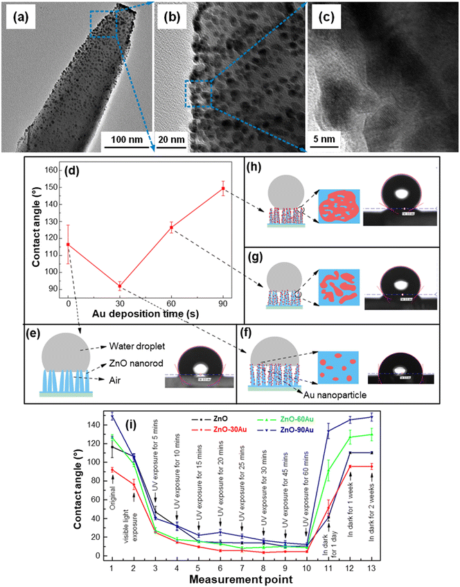 | ||
| Fig. 11 (a–c) TEM images at different magnification levels of a single ZnO NR functionalized with Au NPs. The systems were fabricated by hydrothermal deposition of ZnO NRs on FTO substrates, followed by functionalization with Au through magnetron sputtering for various times (30 s for the specimen imaged in (a–c)). (d) Water contact angle for ZnO NR arrays functionalized with Au for different deposition times. (e–h) Sketches and photographs of a water droplet on the specimens, and the corresponding Au NP distribution on ZnO NRs. (i) Effect of light exposure duration and storage in the dark on the water contact angle of ZnO–Au systems as a function of Au deposition time (30, 60 or 90 min). Reprinted with permission from ref. 40. Copyright 2017, IOP Publishing. | ||
Interestingly, the target systems displayed reversible wettability upon irradiation and subsequent storage in the dark (Fig. 11i). The water contact angle decrease upon visible light illumination observed for all specimens was attributed to the Au-induced surface plasmonic effect.40 Accordingly, electrons rapidly injected into the ZnO CB can promote the formation of hydroxyl groups by reacting with dissolved oxygen, leading to the generation of superoxide species, which, in turn, can further react with water. The result is a contact angle reduction, progressively enhanced by UV illumination prolonged up to 60 min (Fig. 11i). The underlying mechanism has been described as follows.40 UV illumination results in the generation of electrons and holes that can respectively react with lattice Zn and O to yield Zn(I) defective sites and oxygen vacancies.25 Therefore, dissociative chemisorption of atmospheric water is promoted, with the formation of surface –OH groups leading to increased hydrophilicity. Storage in the dark for a sufficiently long time results in a contact angle reversal and a recovery of the original hydrophobicity. In fact, after adsorption of hydroxyl groups, the system surface becomes energetically unstable, whereas adsorption of oxygen molecules, whose bonding with defective sites is stronger, is thermodynamically favoured.109 As a consequence, adsorbed –OH groups are progressively replaced by oxygen, accounting for the return to the original hydrophobic state.
The development of tunable dual-responsive systems with attractive reversible wettability tuning was successfully accomplished by the liquid-phase preparation of ZnO/CuO nanocomposites (caption for Fig. 12).43 Electron microscopy analysis revealed that the branches of the stainless-steel substrate (Fig. 12a) could be uniformly covered by ZnO NR arrays, with the outermost material region characterized by flower and urchin-like hierarchical ZnO/CuO architectures (Fig. 12b and c). The urchin-like microspheres are composed of assembled nano-sheets with sizes <50 nm. These hierarchical structures, yielding an inherently high surface roughness, can readily trap air pockets, anticipating the occurrence of good superhydrophobic properties. Indeed, the system superhydrophobic-to-superhydrophilic switching could be reversibly triggered via thermal treatment (Fig. 12d) and UV exposure (Fig. 12e). Notably, only 1 h of annealing at high (300 °C) and low (150 °C) temperatures (30 min for each) enabled the completion to complete a whole cycle, which could be periodically reproduced with a very limited contact angle hysteresis. Upon UV illumination (Fig. 12e), water contact angle values underwent a gradual decrease with time and the wettability could be switched from superhydrophobic to hydrophilic after 11 h. The initial superhydrophobic state could be restored upon annealing for 30 min at 150 °C. The process mechanism is analogous to the one described for previous systems,43 and proceeds through the surface formation of –OH groups after the initial photocatalytic activation. The coupling of ZnO with CuO can enhance the separation of photogenerated electrons and holes, suppressing their recombination in comparison to the case of bare zinc oxide.115 An additional contribution is provided by the formation of defective sites, promoting the generation of –OH groups and the resultant water contact angle decrease. Indeed, O vacancies can be generated upon high temperature annealing, whereas sample storage in the dark or heating at low temperature results in –OH replacement by O atoms, generating thus the reversal to the initial hydrophobic state. The reversible wettability of ZnO/CuO nanocomposites, which feature also high stability and abrasion resistance, makes them intelligent stimuli-responsive platforms for practical end-uses.
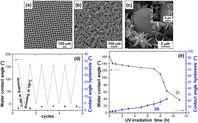 | ||
Fig. 12 Characterization of ZnO/CuO nanocomposite systems with reversible wettability tuning, prepared by chemical bath deposition. The target materials were obtained with different Zn(II)![[thin space (1/6-em)]](https://www.rsc.org/images/entities/char_2009.gif) : :![[thin space (1/6-em)]](https://www.rsc.org/images/entities/char_2009.gif) Cu(II) molar ratios in the starting solutions. SEM images for: (a) the stainless steel mesh substrate and (b and c) a sample obtained using a Zn(II) Cu(II) molar ratios in the starting solutions. SEM images for: (a) the stainless steel mesh substrate and (b and c) a sample obtained using a Zn(II)![[thin space (1/6-em)]](https://www.rsc.org/images/entities/char_2009.gif) : :![[thin space (1/6-em)]](https://www.rsc.org/images/entities/char_2009.gif) Cu(II) molar ratio of 4 Cu(II) molar ratio of 4![[thin space (1/6-em)]](https://www.rsc.org/images/entities/char_2009.gif) : :![[thin space (1/6-em)]](https://www.rsc.org/images/entities/char_2009.gif) 1. Reversible superhydrophobicity–superhydrophilicity switching under annealing at 150 and 300 °C (d), and dependence of water contact angle and contact angle hysteresis on UV irradiation time (e) for the same specimen. Reprinted with permission from ref. 43. Copyright 2019, Elsevier. 1. Reversible superhydrophobicity–superhydrophilicity switching under annealing at 150 and 300 °C (d), and dependence of water contact angle and contact angle hysteresis on UV irradiation time (e) for the same specimen. Reprinted with permission from ref. 43. Copyright 2019, Elsevier. | ||
The material PH and PCO properties can be manipulated by combined control of the morphology and chemical composition even for materials different from ZnO. A representative example is provided by MnO2-based nanosystems, grown on FTO substrates by PE-CVD.44 The systems, containing the β-MnO2 polymorph, displayed a significant morphological evolution as a function of the growth temperature, from dendritic structures (Fig. 13a) to elongated quasi-1D nanothorns (Fig. 13b) protruding from the underlying substrate. These nanostructures are attractive for photocatalytic applications, thanks to the high contact area with the reaction medium.44 In addition, the use of a fluorinated Mn(II) molecular source favoured an even doping of the prepared materials with fluorine, whose content could be modulated as a function of the growth temperature (Fig. 13c). These properties had a direct influence on the system photo-assisted behaviour, which was characterized by the occurrence of a hydrophobic-to-hydrophilic switching upon illumination (Fig. 13d and e). The initial contact angle value was progressively lower for samples grown at higher temperatures, mainly due to the concomitant decrease in fluorine content (Fig. 13c). In fact, the presence of fluorine leads to passivation of defects and, hence, to a reduced O vacancy content, hampering the formation of hydroxyl groups and accounting for the higher initial hydrophobicity.44 Furthermore, the variation of water contact angle between the initial and final states was directly dependent on the growth temperature (Fig. 13e), and turned out to be the highest for the specimen prepared at 100 °C. This behaviour was traced back to the correspondingly higher F percentage, inducing an enhanced metal centre Lewis acidity which, in turn, favourably affects material photoactivity.116 Furthermore, a higher F content produces an enhanced defect passivation, reducing thus electron–hole recombination.117 Although at 400 °C a higher active area (possibly suggesting a higher hydrophobicity) was obtained, this phenomenon could efficiently counterbalance the above described effects. After storage of the specimens in the dark for 12 h at the end of PH tests, the initial surface state was recovered, highlighting the reversibility of the observed behaviour.
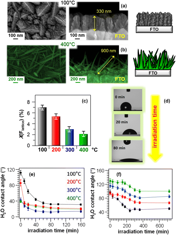 | ||
| Fig. 13 Chemico-physical and functional characterization of MnO2-based nanomaterials fabricated on FTO substrates via PE-CVD at different temperatures, starting from a fluorinated Mn(II) diamine diketonate precursor. (a and b) Representative plane-view (left) and cross-sectional (right) SEM images for samples grown at 100 and 400 °C, along with sketches modelling the morphological evolution from hierarchical dendritic structures to quasi-1D nanosystems. (c) Lattice fluorine contribution, measured by XPS, as a function of the growth temperature. X(Flattice) was calculated from atomic percentages (%at) as (%at Flattice) × 100/[(%at Flattice) + (%at Mn)].44 (d) Photographs of H2O droplets on a specimen fabricated at 100 °C after UV irradiation for different times. (e) PH and (f) PCO performances of MnO2-based nanomaterials: water contact angle vs. irradiation time for as-prepared (e) and methyl stearate-coated systems (f). Reproduced with permission from ref. 44. Copyright 2019, The Royal Society of Chemistry. | ||
PCO performances of the target nanomaterials were tested in the photodecomposition of methyl stearate, a model fatty compound.25 The initial material surface state was hydrophobic (Fig. 13f), due to the presence of the hydrophobic overlayer, and this phenomenon was more pronounced for systems obtained at higher growth temperatures, corresponding to higher surface areas enhancing, in turn, hydrophobicity.25 As already observed for PH (Fig. 13e), the material PCO activity directly depended on the growth temperature, and a higher contact angle variation was observed for the sample grown at 100 °C. The latter result was mainly traced back to the higher fluorine content (see above and Fig. 13c), suppressing electron–hole recombination processes and positively impacting photocatalytic activity.44 Hence, at variance with possible initial predictions, a predominant effect of active area on functional behaviour, which would result in improved performances of the 400 °C-grown sample, could be excluded.
5. Conclusions and perspectives
In this highlight, a brief overview on the design and development of supported first-row transition metal oxide nanostructures for sustainable technologies and environmental applications was presented. In particular, the attention was focused on green, abundant and cost-effective systems based on Mn, Fe and Zn, with regard to end-uses aimed at clean energy production, air purification and self-cleaning purposes. A direct bridge between the above applications is the possibility of benefitting from light activation of the involved processes, as well as from the synergistic combination of material features to attain a widely diversifiable and improved reactivity as a function of the specific end-use.Through the presentation of selected representative case studies, our intention was to provide the readers a picture on the recent evolution of research activities in the target fields, which in our opinion has followed the huge developments in nanomaterial design, fabrication and characterization. Efforts have been dedicated to a discussion of results highlighting how combined control and modulation of nanoarchitectonics, coupled with the development of composite systems, have led to significant steps forward in the engineering of multi-functional oxide-based nanosystems. In this broad realm, key guidelines that can be extracted from the performed research work evidence the relevant influence of the synthesis procedure and processing conditions on the resulting material features. Beside nano-organization, a main role is also played by the system chemical composition, as the controlled choice of metal/oxide counterparts in the resulting composites directly affects the chemical/electronic interplay between the system constituents. The resulting functional behavior in green hydrogen production, air purification, and self-cleaning/anti-fogging end-uses, beyond the specific differences between the various cases, can be thus varied over a broad range already during material preparation, thanks to the availability of various freedom degrees. These issues open the door to additional progress aimed at protecting and valorizing the natural capital towards a more sustainable society.
The above examples pinpoint the importance of constructing functional platforms by design, and we are confident that more functions and utilization could be achieved in the near future by eco-friendly materials for the targeted applications. In this regard, there are still evident shortcomings that should be properly addressed for their full exploitation. First, a complete and detailed correlation between the system chemico-physical and functional properties is still missing on a detailed rational basis, and additional advancements cannot be based on mere “cook-and-look” procedures. A more detailed understanding inevitably requires the aid of advanced theoretical calculations and thorough experimental characterization, whose joint use is indeed a powerful tool to unravel the molecular-level origin of material behavior. Important tools for this are already available, and they are rapidly and significantly evolving under our eyes. These issues are crucial to deepen the fundamental and applied know-how on these intriguing systems, which represent a top priority for the materials science community, and to improve their stability and durability, an inevitable requirement to finally benefit from their applications in actual production and real life.
Author contributions
D. B.: methodology, funding acquisition, writing – original draft; C. M.: conceptualization, project administration, supervision, writing – review and editing.Conflicts of interest
There are no conflicts to declare.Acknowledgements
Financial support from National Council of Research (Progetti di Ricerca @CNR – avviso 2020 – ASSIST), Padova University (P-DiSC#04BIRD2020-UNIPD EUREKA, DOR 2020–2023), AMGA Foundation (NYMPHEA project), and INSTM Consortium (INSTM21PDGASPAROTTO-NANOMAT, INSTM21PDBARMAC-ATENA) is acknowledged. The authors are grateful to Prof. A. Gasparotto for useful support and discussions.Notes and references
- https://www.ipcc.ch/2022/02/28/pr-wgii-ar6/ .
- https://www.eea.europa.eu/soer/2015/synthesis/report/5-riskstohealth .
- Z.-H. Chang, Y.-Z. Chen, Y.-C. Zhang and X.-L. Wang, CrystEngComm, 2022, 24, 5675–5682 RSC.
- C. Jiang, S. J. A. Moniz, M. Khraisheh and J. Tang, Chem. – Eur. J., 2014, 20, 12954–12961 CrossRef CAS PubMed.
- R. Gusain, K. Gupta, P. Joshi and O. P. Khatri, Adv. Colloid Interface Sci., 2019, 272, 102009 CrossRef CAS PubMed.
- S. Saremi-Yarahmadi, K. G. U. Wijayantha, A. A. Tahir and B. Vaidhyanathan, J. Phys. Chem. C, 2009, 113, 4768–4778 CrossRef CAS.
- https://sdgs.un.org/2030agenda .
- F. Rotondo, P. Perchinunno, S. L'Abbate and L. Mongelli, Sci. Rep., 2022, 12, 18513 CrossRef CAS PubMed.
- L. Bigiani, D. Barreca, A. Gasparotto, T. Andreu, J. Verbeeck, C. Sada, E. Modin, O. I. Lebedev, J. R. Morante and C. Maccato, Appl. Catal., A, 2021, 284, 119684 CrossRef CAS.
- L. Bigiani, C. Maccato, T. Andreu, A. Gasparotto, C. Sada, E. Modin, O. I. Lebedev, J. R. Morante and D. Barreca, ACS Appl. Nano Mater., 2020, 3, 9889–9898 CrossRef CAS.
- F. M. Toma, A. Sartorel, M. Iurlo, M. Carraro, P. Parisse, C. Maccato, S. Rapino, B. R. Gonzalez, H. Amenitsch, T. Da Ros, L. Casalis, A. Goldoni, M. Marcaccio, G. Scorrano, G. Scoles, F. Paolucci, M. Prato and M. Bonchio, Nat. Chem., 2010, 2, 826–831 CrossRef CAS PubMed.
- K. Sivula, F. Le Formal and M. Grätzel, ChemSusChem, 2011, 4, 432–449 CrossRef CAS PubMed.
- Y. Li, J. Feng, H. Li, X. Wei, R. Wang and A. Zhou, Int. J. Hydrogen Energy, 2016, 41, 4096–4105 CrossRef CAS.
- S. Dresp, F. Dionigi, M. Klingenhof and P. Strasser, ACS Energy Lett., 2019, 4, 933–942 CrossRef CAS.
- G. Carraro, R. Sugrañez, C. Maccato, A. Gasparotto, D. Barreca, C. Sada, M. Cruz-Yusta and L. Sánchez, Thin Solid Films, 2014, 564, 121–127 CrossRef CAS.
- J. Balbuena, M. Cruz-Yusta and L. Sánchez, J. Nanosci. Nanotechnol., 2015, 15, 6373–6385 CrossRef CAS PubMed.
- R. Sugrañez, J. Balbuena, M. Cruz-Yusta, F. Martín, J. Morales and L. Sánchez, Appl. Catal., A, 2015, 165, 529–536 CrossRef.
- J. Fragoso, D. Barreca, L. Bigiani, A. Gasparotto, C. Sada, O. I. Lebedev, E. Modin, I. Pavlovic, L. Sánchez and C. Maccato, Chem. Eng. J., 2022, 430, 132757 CrossRef CAS.
- J. Fragoso, D. Barreca, L. Bigiani, C. Sada, O. I. Lebedev, E. Modin, I. Pavlovic, L. Sánchez and C. Maccato, ACS Appl. Mater. Interfaces, 2021, 13, 44520–44530 CrossRef CAS PubMed.
- L. Jing, W. Zhou, G. Tian and H. Fu, Chem. Soc. Rev., 2013, 42, 9509–9549 RSC.
- D. Barreca, G. Carraro, A. Gasparotto, C. Maccato, C. Sada, E. Bontempi, M. Brisotto, O. Pliekhova and U. L. Štangar, Environ. Sci. Pollut. Res., 2016, 23, 20350–20359 CrossRef CAS PubMed.
- https://www.ipcc.ch/ .
- I. F. Wahab, A. R. Bushroa, S. Wee Teck, T. T. Azmi, M. Z. Ibrahim and J. W. Lee, J. Mater. Res. Technol., 2023, 23, 687–714 CrossRef CAS.
- A. V. Rudakova and A. V. Emeline, Colloid J., 2021, 83, 20–48 CrossRef CAS.
- D. Barreca, A. Gasparotto, C. Maccato, E. Tondello, U. L. Štangar and S. R. Patil, Surf. Coat. Technol., 2009, 203, 2041–2045 CrossRef CAS.
- D. Bekermann, A. Gasparotto, D. Barreca, A. Devi, R. A. Fischer, M. Kete, U. L. Stangar, O. I. Lebedev, C. Maccato, E. Tondello and G. Van Tendeloo, ChemPhysChem, 2010, 11, 2337–2340 CrossRef CAS PubMed.
- O. Carp, C. L. Huisman and A. Reller, Prog. Solid State Chem., 2004, 32, 33–177 CrossRef CAS.
- R. Gade, J. Ahemed, K. L. Yanapu, S. Y. Abate, Y.-T. Tao and S. Pola, J. Environ. Chem. Eng., 2018, 6, 4504–4513 CrossRef CAS.
- M. Saeed, M. Muneer, A. U. Haq and N. Akram, Environ. Sci. Pollut. Res., 2022, 29, 293–311 CrossRef CAS PubMed.
- I. Khan, K. Saeed, N. Ali, I. Khan, B. Zhang and M. Sadiq, J. Environ. Chem. Eng., 2020, 8, 104364 CrossRef CAS.
- D. Chen, Y. Cheng, N. Zhou, P. Chen, Y. Wang, K. Li, S. Huo, P. Cheng, P. Peng, R. Zhang, L. Wang, H. Liu, Y. Liu and R. Ruan, J. Cleaner Prod., 2020, 268, 121725 CrossRef CAS.
- Y. Gao, N. Zhang, C. Wang, F. Zhao and Y. Yu, ACS Appl. Energy Mater., 2020, 3, 666–674 CrossRef CAS.
- L. Bigiani, T. Andreu, C. Maccato, E. Fois, A. Gasparotto, C. Sada, G. Tabacchi, D. Krishnan, J. Verbeeck, J. R. Morante and D. Barreca, J. Mater. Chem. A, 2020, 8, 16902–16907 RSC.
- G. Carraro, C. Maccato, A. Gasparotto, T. Montini, S. Turner, O. I. Lebedev, V. Gombac, G. Adami, G. Van Tendeloo, D. Barreca and P. Fornasiero, Adv. Funct. Mater., 2014, 24, 372–378 CrossRef CAS.
- K. Ariga and J. Li, Adv. Mater., 2016, 28, 987–988 CrossRef CAS PubMed.
- K. Ariga, Q. Ji, W. Nakanishi, J. P. Hill and M. Aono, Mater. Horiz., 2015, 2, 406–413 RSC.
- D. Bekermann, D. Barreca, A. Gasparotto and C. Maccato, CrystEngComm, 2012, 14, 6347–6358 RSC.
- D. Nunes, A. Pimentel, L. Santos, P. Barquinha, L. Pereira, E. Fortunato and R. Martins, Metal Oxide Nanostructures: Synthesis, Properties and Applications, ed. G. Korotcenkov, Elsevier, 2019 Search PubMed.
- Tailored Functional Oxide Nanomaterials: From Design to Multi-Purpose Application, ed. C. Maccato and D. Barreca, Wiley-VCH, 2022 Search PubMed.
- Y. Wei, H. Du, J. Kong, V.-T. Tran, J. Kai Koh, C. Zhao and C. He, Nanotechnology, 2017, 28, 445404 CrossRef PubMed.
- Y. S. Ding, X. F. Shen, S. Gomez, H. Luo, M. Aindow and S. L. Suib, Adv. Funct. Mater., 2006, 16, 549–555 CrossRef CAS.
- A. Pastor, J. Balbuena, M. Cruz-Yusta, I. Pavlovic and L. Sánchez, Chem. Eng. J., 2019, 368, 659–667 CrossRef CAS.
- E. Velayi and R. Norouzbeigi, Surf. Coat. Technol., 2019, 367, 252–261 CrossRef CAS.
- D. Barreca, F. Gri, A. Gasparotto, G. Carraro, L. Bigiani, T. Altantzis, B. Žener, U. Lavrenčič Štangar, B. Alessi, D. B. Padmanaban, D. Mariotti and C. Maccato, Nanoscale, 2019, 11, 98–108 RSC.
- C. E. Flynn, S.-W. Lee, B. R. Peelle and A. M. Belcher, Acta Mater., 2003, 51, 5867–5880 CrossRef CAS.
- B. Neltner, B. Peddie, A. Xu, W. Doenlen, K. Durand, D. S. Yun, S. Speakman, A. Peterson and A. Belcher, ACS Nano, 2010, 4, 3227–3235 CrossRef CAS PubMed.
- P.-Y. Chen, X. Dang, M. T. Klug, J. Qi, N.-M. Dorval Courchesne, F. J. Burpo, N. Fang, P. T. Hammond and A. M. Belcher, ACS Nano, 2013, 7, 6563–6574 CrossRef CAS PubMed.
- C. Huang, Q. Zhou, D. Duan, L. Yu, W. Zhang, Z. Wang, J. Liu, B. Peng, P. An, J. Zhang, L. Li, J. Yu and Y. Yu, Energy Environ. Sci., 2022, 15, 4647–4658 RSC.
- M. Cargnello, A. Gasparotto, V. Gombac, T. Montini, D. Barreca and P. Fornasiero, Eur. J. Inorg. Chem., 2011, 2011, 4309–4323 CrossRef CAS.
- https://www.nationalgrid.com/stories/energy-explained/hydrogen-colour-spectrum .
- Y. Zhao, B. Jin, A. Vasileff, Y. Jiao and S.-Z. Qiao, J. Mater. Chem. A, 2019, 7, 8117–8121 RSC.
- X. Song, T. Yang, H. Du, W. Dong and Z. Liang, J. Electroanal. Chem., 2016, 760, 59–63 CrossRef CAS.
- R. Naeem, M. A. Ehsan, R. Yahya, M. Sohail, H. Khaledi and M. Mazhar, Dalton Trans., 2016, 45, 14928–14939 RSC.
- M. A. Mansoor, M. Mazhar, V. McKee and Z. Arifin, Polyhedron, 2014, 75, 135–140 CrossRef CAS.
- L. Zeng, K. Zhou, L. Yang, G. Du, L. Liu and W. Zhou, ACS Appl. Energy Mater., 2018, 1, 6279–6287 CrossRef CAS.
- M. E. G. Lyons and M. P. Brandon, J. Electroanal. Chem., 2010, 641, 119–130 CrossRef CAS.
- L. Meda and L. Abbondanza, Rev. Adv. Sci. Eng., 2013, 2, 200–207 CrossRef.
- N. Armaroli and V. Balzani, Chem. – Eur. J., 2016, 22, 32–57 CrossRef CAS PubMed.
- X. Chen, Z. Zhang, L. Chi, A. K. Nair, W. Shangguan and Z. Jiang, Nano-Micro Lett., 2016, 8, 1–12 CrossRef CAS PubMed.
- D. Barreca, G. Carraro, V. Gombac, A. Gasparotto, C. Maccato, P. Fornasiero and E. Tondello, Adv. Funct. Mater., 2011, 21, 2611–2623 CrossRef CAS.
- T. Zhu, M. N. Chong and E. S. Chan, ChemSusChem, 2014, 7, 2974–2997 CrossRef CAS PubMed.
- L. Yang, H. Zhou, T. Fan and D. Zhang, Phys. Chem. Chem. Phys., 2014, 16, 6810–6826 RSC.
- W. Wang, L. Kuai, W. Cao, M. Huttula, S. Ollikkala, T. Ahopelto, A.-P. Honkanen, S. Huotari, M. Yu and B. Geng, Angew. Chem., Int. Ed., 2017, 56, 14977–14981 CrossRef CAS PubMed.
- Z. S. Luo, E. Irtem, M. Ibanez, R. Nafria, S. Marti-Sanchez, A. Genc, M. de la Mata, Y. Liu, D. Cadavid, J. Llorca, J. Arbiol, T. Andreu, J. R. Morante and A. Cabot, ACS Appl. Mater. Interfaces, 2016, 8, 17435–17444 CrossRef CAS PubMed.
- F. Mattelaer, T. Bosserez, J. Ronge, J. A. Martens, J. Dendooven and C. Detavernier, RSC Adv., 2016, 6, 98337–98343 RSC.
- C.-H. Kuo, W. Li, L. Pahalagedara, A. M. El-Sawy, D. Kriz, N. Genz, C. Guild, T. Ressler, S. L. Suib and J. He, Angew. Chem., Int. Ed., 2015, 54, 2345–2350 CrossRef CAS PubMed.
- J. G. Vos, T. A. Wezendonk, A. W. Jeremiasse and M. T. M. Koper, J. Am. Chem. Soc., 2018, 140, 10270–10281 CrossRef CAS PubMed.
- Y. Kuang, M. J. Kenney, Y. Meng, W.-H. Hung, Y. Liu, J. E. Huang, R. Prasanna, P. Li, Y. Li, L. Wang, M.-C. Lin, M. D. McGehee, X. Sun and H. Dai, Proc. Natl. Acad. Sci. U. S. A., 2019, 116, 6624 CrossRef CAS PubMed.
- W.-H. Huang and C.-Y. Lin, Faraday Discuss., 2019, 215, 205–215 RSC.
- Y. Huang, L. Hu, R. Liu, Y. Hu, T. Xiong, W. Qiu, M. S. Balogun, A. Pan and Y. Tong, Appl. Catal., A, 2019, 251, 181–194 CrossRef CAS.
- A. Talaiekhozani, S. Rezania, K.-H. Kim, R. Sanaye and A. M. Amani, J. Cleaner Prod., 2021, 278, 123895 CrossRef CAS.
- R. Sugrañez, J. I. Álvarez, M. Cruz-Yusta, I. Mármol, J. Morales, J. Vila and L. Sánchez, Build. Environ., 2013, 69, 55–63 CrossRef.
- H. Liu, H. Mei, N. Miao, L. Pan, Z. Jin, G. Zhu, J. Gao, J. Wang and L. Cheng, Chem. Eng. J., 2021, 414, 128748 CrossRef CAS.
- J. Balbuena, G. Carraro, M. Cruz, A. Gasparotto, C. Maccato, A. Pastor, C. Sada, D. Barreca and L. Sánchez, RSC Adv., 2016, 6, 74878–74885 RSC.
- Z. Zhang, L. Bai, Z. Li, Y. Qu and L. Jing, J. Mater. Chem. A, 2019, 7, 10879–10897 RSC.
- J. Z. Bloh, A. Folli and D. E. Macphee, RSC Adv., 2014, 4, 45726–45734 RSC.
- A. Gasparotto, G. Carraro, C. Maccato, C. Sada, J. Balbuena, M. Cruz-Yusta, L. Sánchez, N. Vodišek, U. Lavrencic Štangar and D. Barreca, CrystEngComm, 2018, 20, 1282–1290 RSC.
- J. Balbuena, M. Cruz-Yusta, A. Pastor and L. Sánchez, J. Alloys Compd., 2018, 735, 1553–1561 CrossRef CAS.
- J. Fragoso, M. A. Oliva, L. Camacho, M. Cruz-Yusta, G. de Miguel, F. Martin, A. Pastor, I. Pavlovic and L. Sánchez, Chemosphere, 2021, 275, 130030 CrossRef CAS PubMed.
- J. Balbuena, M. Cruz-Yusta, A. L. Cuevas, M. C. López-Escalante, F. Martín, A. Pastor and L. Sánchez, RSC Adv., 2016, 6, 92917–92922 RSC.
- J. Balbuena, J. M. Calatayud, M. Cruz-Yusta, P. Pardo, F. Martín, J. Alarcón and L. Sánchez, Dalton Trans., 2018, 47, 6590–6597 RSC.
- R. A. Senthil, A. Priya, J. Theerthagiri, A. Selvi, P. Nithyadharseni and J. Madhavan, Ionics, 2018, 24, 3673–3684 CrossRef CAS.
- X. Song, G. Qin, G. Cheng, W. Jiang, X. Chen, W. Dai and X. Fu, Appl. Catal., A, 2021, 284, 119761 CrossRef CAS.
- W. Huo, T. Cao, W. Xu, Z. Guo, X. Liu, H.-C. Yao, Y. Zhang and F. Dong, Chin. J. Catal., 2020, 41, 268–275 CrossRef CAS.
- H. Liu, H. Yang, J. Fan, C. Zhou, J. Zhang, Y. Wan, Z. Liu, J. Chen, G. Wang and R. Wang, Chem. Phys. Lett., 2020, 755, 137702 CrossRef CAS.
- G. Jiang, J. Cao, M. Chen, X. Zhang and F. Dong, Appl. Surf. Sci., 2018, 458, 77–85 CrossRef CAS.
- L. Zhu, H. Li, Z. Liu, P. Xia, Y. Xie and D. Xiong, J. Phys. Chem. C, 2018, 122, 9531–9539 CrossRef CAS.
- T. Shen, X. Shi, J. Guo, J. Li and S. Yuan, Chem. Eng. J., 2021, 408, 128014 CrossRef CAS.
- Y. Huang, D. Zhu, Q. Zhang, Y. Zhang, J.-J. Cao, Z. Shen, W. Ho and S. C. Lee, Appl. Catal., A, 2018, 234, 70–78 CrossRef CAS.
- M. J. Hernández Rodríguez, E. Pulido Melián, O. González Díaz, J. Araña, M. Macías, A. González Orive and J. M. Doña Rodríguez, J. Mol. Catal. A: Chem., 2016, 413, 56–66 CrossRef.
- S.-M. Lam, J.-C. Sin, A. Z. Abdullah and A. R. Mohamed, Ceram. Int., 2013, 39, 2343–2352 CrossRef CAS.
- J. Xie, Z. Zhou, Y. Lian, Y. Hao, X. Liu, M. Li and Y. Wei, Ceram. Int., 2014, 40, 12519–12524 CrossRef CAS.
- F. Zheng, H. Lu, M. Guo, M. Zhang and Q. Zhen, J. Mater. Chem. C, 2015, 3, 7612–7620 RSC.
- Y. Liu, H. He, J. Li, W. Li, Y. Yang, Y. Li and Q. Chen, RSC Adv., 2015, 5, 46928–46934 RSC.
- D. Li and H. Haneda, J. Photochem. Photobiol., A, 2003, 160, 203–212 CrossRef CAS.
- D. Li, H. Haneda, N. Ohashi, S. Hishita and Y. Yoshikawa, Catal. Today, 2004, 93, 895–901 CrossRef.
- B. Subash, A. Senthilraja, P. Dhatshanamurthi, M. Swaminathan and M. Shanthi, Spectrochim. Acta, Part A, 2013, 115, 175–182 CrossRef CAS PubMed.
- R. S. Vemuri, M. H. Engelhard and C. V. Ramana, ACS Appl. Mater. Interfaces, 2012, 4, 1371–1377 CrossRef CAS PubMed.
- H. Ishihara, G. K. Kannarpady, K. R. Khedir, J. Woo, S. Trigwell and A. S. Biris, Phys. Chem. Chem. Phys., 2011, 13, 19553–19560 RSC.
- M. Saleem, M. F. Al-Kuhaili, S. M. A. Durrani, A. H. Y. Hendi, I. A. Bakhtiari and S. Ali, Int. J. Hydrogen Energy, 2015, 40, 12343–12351 CrossRef CAS.
- S.-M. Lam, J.-C. Sin, A. Z. Abdullah and A. R. Mohamed, Sep. Purif. Technol., 2014, 132, 378–387 CrossRef CAS.
- Y. Wang, Q. Wang, X. Zhan, F. Wang, M. Safdar and J. He, Nanoscale, 2013, 5, 8326–8339 RSC.
- K. C. Christoforidis, T. Montini, E. Bontempi, S. Zafeiratos, J. J. D. Jaén and P. Fornasiero, Appl. Catal., A, 2016, 187, 171–180 CrossRef CAS.
- C. Maccato, L. Bigiani, D. Barreca and A. Gasparotto, Surf. Sci. Spectra, 2021, 28, 024003 CrossRef CAS.
- E. Ebrahimi, M. Irfan, F. Shabani, Y. Kocak, B. Karakurt, E. Erdem, H. V. Demir and E. Ozensoy, ChemCatChem, 2020, 12, 6329–6343 CrossRef CAS.
- L. Zhang, R. Dillert, D. Bahnemann and M. Vormoor, Energy Environ. Sci., 2012, 5, 7491–7507 RSC.
- D. Barreca, G. Carraro, A. Gasparotto, C. Maccato, F. Rossi, G. Salviati, M. Tallarida, C. Das, F. Fresno, D. Korte, U. L. Štangar, M. Franko and D. Schmeisser, ACS Appl. Mater. Interfaces, 2013, 5, 7130–7138 CrossRef CAS PubMed.
- R. Mardosaitė, A. Jurkevičiūtė and S. Račkauskas, Cryst. Growth Des., 2021, 21, 4765–4779 CrossRef.
- E. L. Papadopoulou, M. Barberoglou, V. Zorba, A. Manousaki, A. Pagkozidis, E. Stratakis and C. Fotakis, J. Phys. Chem. C, 2009, 113, 2891–2895 CrossRef CAS.
- J. A. Howarter and J. P. Youngblood, Macromol. Rapid Commun., 2008, 29, 455–466 CrossRef CAS.
- I. R. Durán and G. Laroche, Adv. Colloid Interface Sci., 2019, 263, 68–94 CrossRef PubMed.
- Y. Lai, Y. Tang, J. Gong, D. Gong, L. Chi, C. Lin and Z. Chen, J. Mater. Chem., 2012, 22, 7420–7426 RSC.
- H. Zhu, S. Cai, G. Liao, Z. F. Gao, X. Min, Y. Huang, S. Jin and F. Xia, ACS Catal., 2021, 11, 14751–14771 CrossRef CAS.
- D. Quéré, Rep. Prog. Phys., 2005, 68, 2495 CrossRef.
- H. Fang, Y. Guo, T. Wu and Y. Liu, New J. Chem., 2018, 42, 12779–12786 RSC.
- A. Gasparotto, D. Barreca, D. Bekermann, A. Devi, R. A. Fischer, P. Fornasiero, V. Gombac, O. I. Lebedev, C. Maccato, T. Montini, G. Van Tendeloo and E. Tondello, J. Am. Chem. Soc., 2011, 133, 19362–19365 CrossRef CAS PubMed.
- D. Barreca, G. Carraro, A. Gasparotto, C. Maccato, C. Sada, A. P. Singh, S. Mathur, A. Mettenborger, E. Bontempi and L. E. Depero, Int. J. Hydrogen Energy, 2013, 38, 14189–14199 CrossRef CAS.
| This journal is © The Royal Society of Chemistry 2023 |

